Article

Experimental Analysis of Flow Separation Control on UAV Propellers Using Dielectric Barrier Discharge Plasma Actuators

1
Department of Aerospace Engineering, Iowa State University, Ames, IA 50011, USA
2
Department of Mechanical Engineering, American University of Bahrain, Al-Riffa 915, Bahrain
3
Department of Mechanical Engineering, Pennsylvania State University, University Park, PA 16802, USA
*
Authors to whom correspondence should be addressed.
Aerospace 2026, 13(8), 668; https://doi.org/10.3390/aerospace13080668
Submission received: 26 June 2026 / Revised: 20 July 2026 / Accepted: 23 July 2026 / Published: 26 July 2026

Abstract

Dielectric Barrier Discharge (DBD) plasma actuators have shown considerable potential for aerodynamic flow control over fixed wings and helicopter rotors. However, their application to small unmanned aerial vehicle (UAV) propellers operating at high rotational speeds remains largely unexplored. This study experimentally investigates the effectiveness of leading-edge AC-DBD plasma actuators in improving the aerodynamic performance of rotating UAV propellers under hovering conditions. A custom-built experimental test stand was developed to measure thrust, rotational speed, and motor power consumption while supplying high voltage to the rotating blades through high-speed slip rings. A series of 3D-printed propellers with different blade pitch angles was tested at rotational speeds up to 4000 rpm. The results showed negligible performance changes for low-pitch propellers, whereas significant improvements were observed under separated-flow conditions. At nearly constant rotational speed and thrust, plasma actuation reduced the propeller power coefficient by up to 7.66%, resulting in a maximum 9.42% increase in Figure of Merit (FoM). The greatest benefits were obtained for intermediate blade pitch angles, while no measurable improvement was observed under severe separation conditions. These findings demonstrate that plasma actuation is most effective within an intermediate separated-flow regime and highlight its potential as a lightweight active flow-control technology for electrically powered UAVs.

1. Introduction

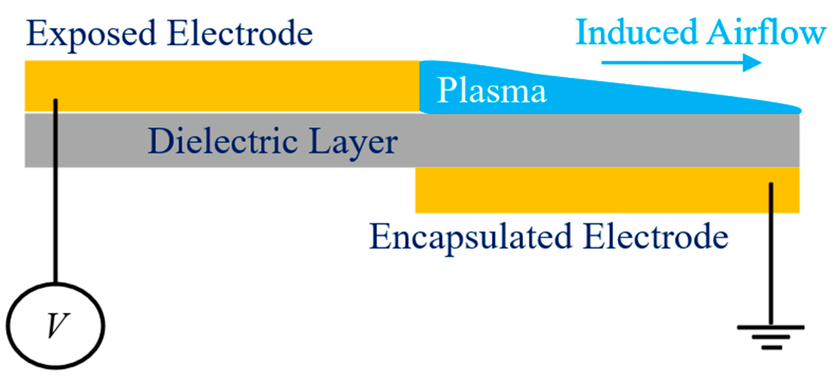
DBD (Dielectric Barrier Discharge) plasma actuators are widely used in aerospace engineering for flow control applications [1]. When a high voltage V is applied to the electrodes, either in alternating current (AC-DBD) or nanosecond pulses (NS-DBD), the air surrounding the encapsulated electrode becomes ionized, creating a plasma streak as shown in Figure 1. This ionization, coupled with a strong electric field, generates a body force that induces gas flow along the dielectric surface, resulting in a wall jet [2]. Plasma-induced wall jets are commonly used to mitigate boundary layer separation and delay airfoil stall. Roth et al. were among the pioneers to demonstrate the potential benefits of DBD plasma actuation for flow control nearly two decades ago [3]. Since then, extensive research has explored the use of plasma actuators in various flow control applications [4,5,6]. This approach remains a dynamic area of investigation, with applications ranging from airfoils to road vehicles [7,8,9]. Plasma-based flow control techniques offer several advantages over traditional active flow control methods since they respond almost instantaneously when activated by high-voltage pulses [8], eliminate the need for moving components, consume relatively low electrical power for operation, and feature a straightforward system design, allowing easy integration into existing structures [10].
While DBD plasma actuation of fixed wings is extensively reported, previous studies have demonstrated that actuation can also provide notable aerodynamic benefits for helicopter rotors, including increased lift, reduced torque, and improved hover efficiency. Starikovskiy et al. experimentally showed that NS-DBD plasma actuators mounted on blades rotating at 1080 rpm can significantly mitigate flow separation at high angles of attack, with reported lift increases of up to ~50%, depending on actuation frequency [11]. Zhao et al. demonstrated that leading-edge AC-DBD plasma actuation applied to a helicopter rotor operating at 550 rpm increased the thrust coefficient by up to ~20% at post-stall collective pitches [12]. Polonsky et al. reported that pulsed DBD plasma actuation on a two-bladed helicopter rotor rotating at 220 rpm reduced blade drag and increased post-stall lift by up to ~30%, resulting in a net aerodynamic efficiency gain at low Reynolds numbers (Re) [13]. In a subsequent study, they also showed that DBD plasma actuation on a model helicopter rotor tested at rotational speeds up to 1300 rpm reduced broadband and tonal noise by up to 8 dB and 3 dB, respectively, while simultaneously increasing the rotor FoM by approximately 25% [14].
With the well documented effects of DBD plasma actuation as an effective flow separation control for fixed wings and the promising effects seen for rather large rotors spinning at relatively low speeds, the research in the current paper aims to investigate the benefits of aerodynamic enhancement of actuation on a tested small-scale UAV propeller spinning at up to 4000 rpm. To the best of authors’ knowledge, this is the first experimental study to investigate AC-DBD plasma flow control on small UAV propellers operating at rotational speeds up to 4000 rpm and constitutes the primary novelty of the present work. This paper presents a systematic experimental investigation into the application of leading-edge DBD plasma actuators for active flow control on small UAV propellers operating under hovering conditions. Parametric experiments were conducted over a range of blade pitch angles, rotational speeds, and actuation voltages to quantify their influence on thrust, power consumption, and propeller FoM. The results identify the operating conditions under which plasma actuation provides measurable aerodynamic benefits and establish the effectiveness and limitations of this approach for tested UAV propellers.

2. Experimental Setup and Test Model

2.1. Propeller Model Used in This Study

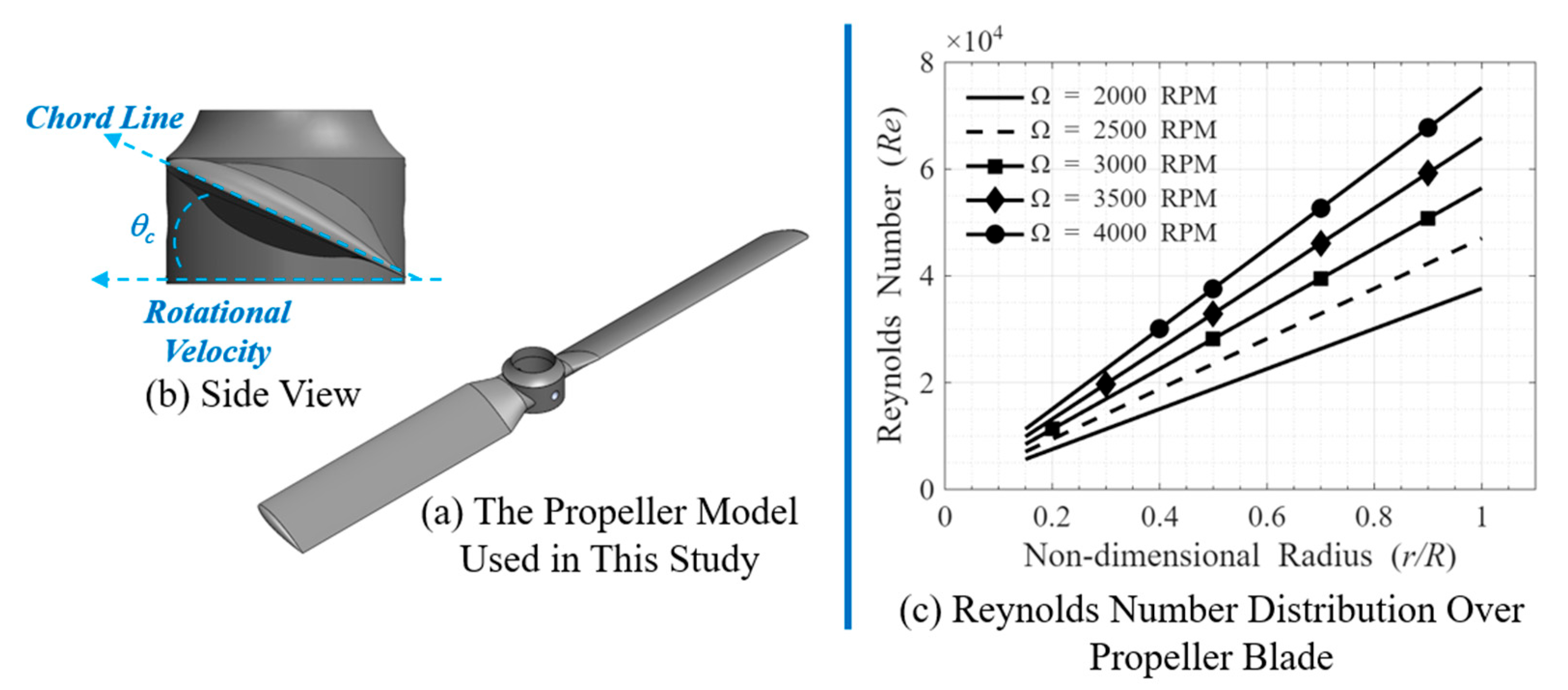
The experimental study was performed in the Advanced Flow Diagnostic and Experimental Aerodynamic Laboratory located at the Iowa State University, modeling a propeller in hovering conditions with no incoming airflow. The test model used in the present study was an untwisted two-blade propeller with a radius R = 114 mm, a constant chord of c = 22 mm and a constant pitch angle θc, presented in Figure 2. A basic propeller design was adopted in this work to simplify the process of applying DBD plasma actuators on the small propeller blades, with the primary objective being the study of flow separation control on the propeller. The blades feature a NACA 4412 airfoil and, depending on the test case, multiple propellers with different θc were designed and 3D-printed using a glass-filled, high-stiffness SLA resin (i.e., Rigid 10K Resin) to assess actuation performance over a range of pitch conditions.

2.2. Experimental Test Stand & Measurement Systems Used in This Study

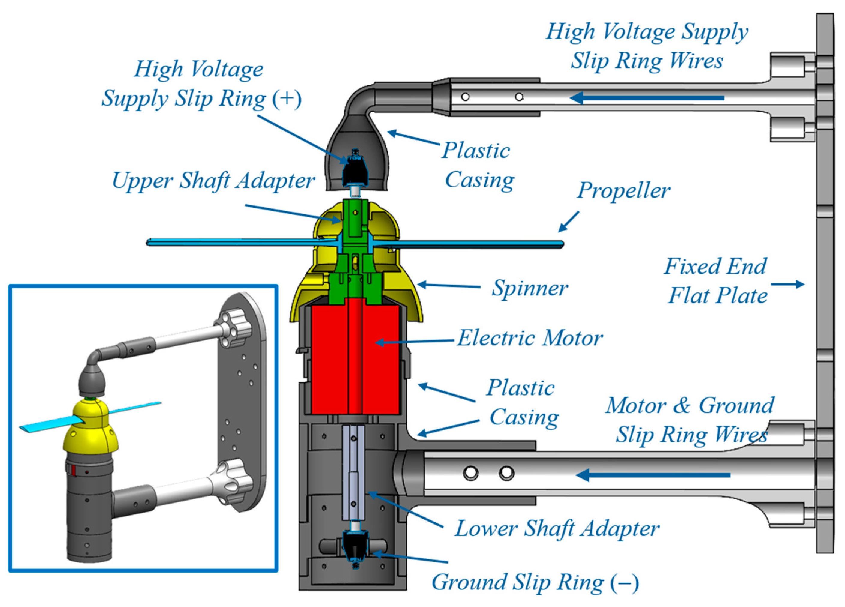
As shown in Figure 3, a plastic enclosure was also designed and 3D printed out of PLA to ensure proper assembly, while a spinner protected the propeller hub. The end plate of the test stand was mounted on a highly sensitive load cell (i.e., ATI, model F/T Sensor: mini45 IP65) that was fixed to the main test rig, which was a custom-built 80/20 alumina stage to measure the aerodynamic forces produced by the UAV propeller. A careful calibration procedure was performed to quantify the measurement uncertainty of the load cell by applying a set of standard weights to the load cell, similar to the procedure discussed in earlier studies of Samad et al. [15]. Based on the quantitative comparison of the measurement results against the nominal values of the applied standard weights, the load cell was found to have a measurement uncertainty within ±2.0% with an applied force up to 50 N. Moreover, the electric current supplied to the brushless motor was also measured by using a Hall Effect Current Transducer (i.e., CR Magnetics, CR5410 AC/DC, St. Louis, MO, USA) with an accuracy of ±1.0%, enabling the measurement of the tested UAV propeller model’s power consumption. During testing, aerodynamic force and motor power consumption data were sampled at 5000 Hz using a data acquisition system (NI USB-6218. It should be noted that each operating condition tested in this work was repeated multiple times to assess experimental repeatability. While the manufacturer-specified uncertainties of the load cell and electrical power measurement system were ±2% and ±1%, respectively, the variation observed between repeated thrust and power measurements was approximately ±2.5%, representing the combined influence of measurement uncertainty and test-to-test experimental variability.
In the present study, a brushless motor (i.e., Scorpion SII-4035-380KV, Hong Kong) coupled with an Electronic Speed Controller (RC Electric Parts, 80 Amps XT 90 4.00 mm, Shenzhen, China), were used to drive the tested UAV propeller model. The motor was driven by a direct current (DC) supply source (i.e., VOLTEQ HY3050EX, San Jose, CA, USA) at a constant voltage of 16 V. During the experiments, the propeller model was operated under variable rotational speed, with the desired rotational speed manually set using an ESC servo speed controller (i.e., ESC Servo Tester CCPM Consistency Master Checker, Shenzhen, China) and measured using a digital tachometer (i.e., MONARCH PLT200, Amherst, NH, USA). Any outside factors acting on the propeller (e.g., such as flow separation control) would therefore affect the rotation speed and motor power consumption during operations.
Moreover, a pair of high-voltage, high-speed slip rings (i.e., Mercotac Model 104, Carlsbad, CA, USA) was used to supply high voltage to the DBD plasma actuators mounted on the rotating propeller, as shown in Figure 3. The slip rings are rated for rotational speeds up to 7500 rpm and practically impose no limitation on the applied voltage. Each slip ring has a single-conductor design and can function as either a high-voltage input or a ground, requiring two units to complete the electrical circuit. Accordingly, one slip ring was installed above the propeller plane to provide the high-voltage input, while the second was mounted below the propeller plane and connected to the plasma generator ground. Custom shaft adapters were designed and 3D-printed using Rigid 10K resin to ensure proper integration with the shaft, wiring, and associated components.

2.3. Dielectric Barrier Discharge (DBD) Plasma Actuators Design Used in This Study

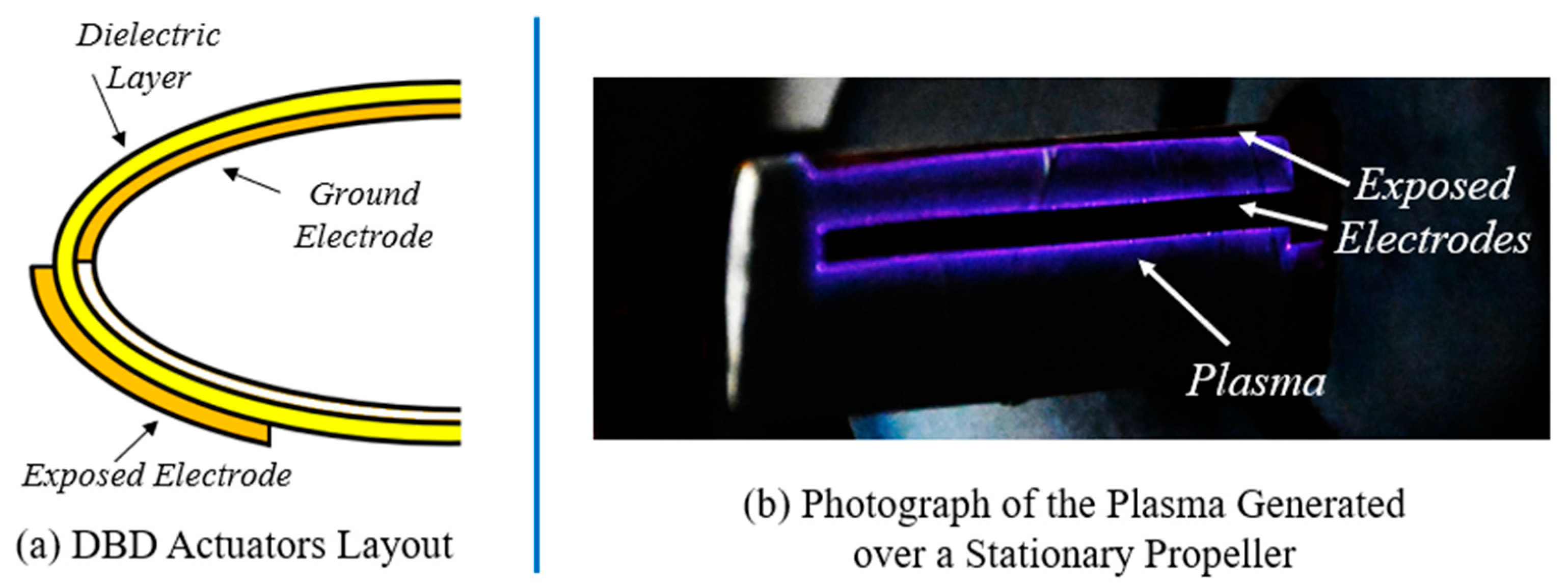
As depicted in Figure 4a, DBD plasma actuators were placed on the leading edge of the propeller model with the electrodes made using ~70 μm thin copper sheets. The ground electrode was applied to the bare blade and wrapped around the leading edge to cover both the suction and pressure sides of the propeller, covering up to 80% of the blade area except for a small region near the trailing edge of the blades. Four layers of highly insulating Kapton film, 130 μm in thickness each, were then applied on top of the ground electrode and wrapped around the entire blade surface to serve as the dielectric barrier, separating the ground electrodes from the exposed electrodes. Next, the propeller with the dielectric layer was spray painted with several layers of all-weather protective Enamel painting (i.e., RustoleumTM Smoke Grey Flat Protective Enamel). The exposed electrode was placed exactly in such a way that plasma would form exactly the leading edge as shown in Figure 4a and extended between 15% and 90% the blade radius. During the initial design stages, it was found that extending the exposed electrode beyond r/R ≈ 90% increased the chances of short-circuiting between the ground and exposed electrodes and was the reason why coverage was limited to that extent only. Furthermore, different actuator layouts can be easily created by varying the locations of the ground and/or exposed electrodes, as illustrated by the photograph of plasma manifestation over a static propeller with one additional exposed electrode compared with the configuration used in this work, as shown in Figure 4b.
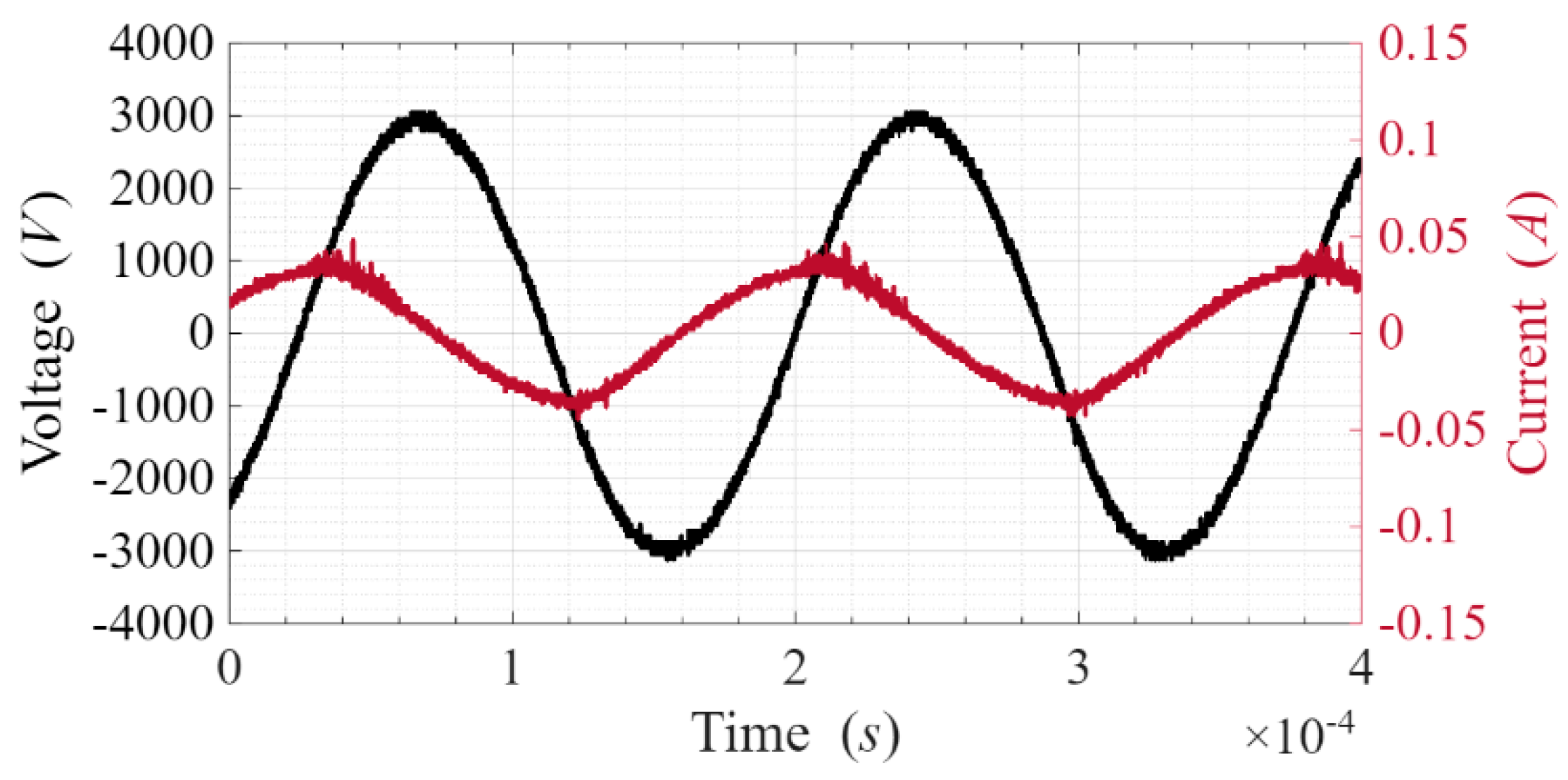
During experiments, the actuators were powered by a high-voltage AC power source (Nanjing Suman, model CTP-2000K, Pasadena, CA, USA). The voltage applied Vac was measured by a voltage attenuator (i.e., Tektronix P6015 high-voltage Probe, Beaverton, OR, USA) and a mixed domain oscilloscope (i.e., Tektronix MDO3102) while the electric current Iac was measured using a current transducer (i.e., Pearson Current Monitor Model 2877 Palo Alto, CA, USA). The voltage and current signals were monitored and measured throughout the testing time, as shown in the example of Figure 5, by taking multiple measurements at various time intervals, which were then used to calculate the power consumption of the DBD plasma actuators Pac using Equation (1).
P a c = 1 T 0 T V a c t × I a c t d t

3. Measurement Results & Discussions

3.1. Propeller Performance Enhancement Using DBD Plasma Actuators

In this study, the experimental procedure began with the fabrication of a propeller with a prescribed constant pitch angle θc. The DBD plasma actuators were then integrated onto the printed propeller following the procedure described earlier. Subsequently, the propeller was mounted on the experimental test stand, and all electrical connections to the plasma generator were soldered and secured. The spinner was installed to enclose the rotor system, and the entire test stand was rigidly fixed to the load cell and the custom-built 80/20 aluminum stage.
After completing the load cell calibration, the propeller was operated under manual speed control. The rotation speed was gradually increased from rest using an ESC servo speed controller until the target rotational speed was reached. As noted previously, external disturbances could influence both the rotation speed and the motor power consumption. Once the propeller reached steady-state operation for approximately 30 s, the DBD plasma actuators were activated to initiate plasma formation along the leading edge of the rotating propeller.
Since the rotation speed was allowed to vary freely, effective flow-separation control by the DBD plasma actuators was expected to result in an increase in rotation speed due to the reduction in drag associated with separated flow. If no measurable change in rotation speed was observed before and after plasma actuation, it was inferred that large-scale flow separation was either absent or insufficiently developed for plasma actuation to produce a measurable aerodynamic benefit. This interpretation follows the methodology proposed by Polonsky et al. [13]. Conversely, when a noticeable change in rotation speed was detected, the propeller was allowed to operate for an additional 30 s to reach a new steady-state condition. Finally, with the plasma actuators remaining active, the propeller rotation speed was manually reduced back to its pre-actuation value, allowing a direct comparison of thrust force and motor power consumption before and after actuation at the same rotational speed. For the experiments presented in this study, the applied actuator voltage was Vac = 6 kV, the corresponding power was calculated to be Pac ≈ 4 W whereas the set frequency of actuation was fac ≈ 5.5 kHz.
Initial experiments with propellers having a pitch angle of θc = 6° and θc = 12° showed no changes in rotation speed before and after actuation and it was thus assumed that the flow around the rotor blade was mainly attached for those pitch angles. However, when other propellers with higher pitch angles such as θc = 15° and θc = 18° were used, significant changes to the rotation speed were observed, consistent with the presence of separated flow prior to plasma actuation and its subsequent mitigation following plasma activation. The absence of measurable improvement for θc = 6° and 12° suggests that the boundary layer remained largely attached under these operating conditions. Since DBD plasma actuators primarily delay or suppress separation rather than increase circulation directly, little aerodynamic benefit would be expected when the baseline flow is already attached. This observation is consistent with previous studies on fixed airfoils, where plasma actuation produced minimal performance improvements below the natural stall angle [16].
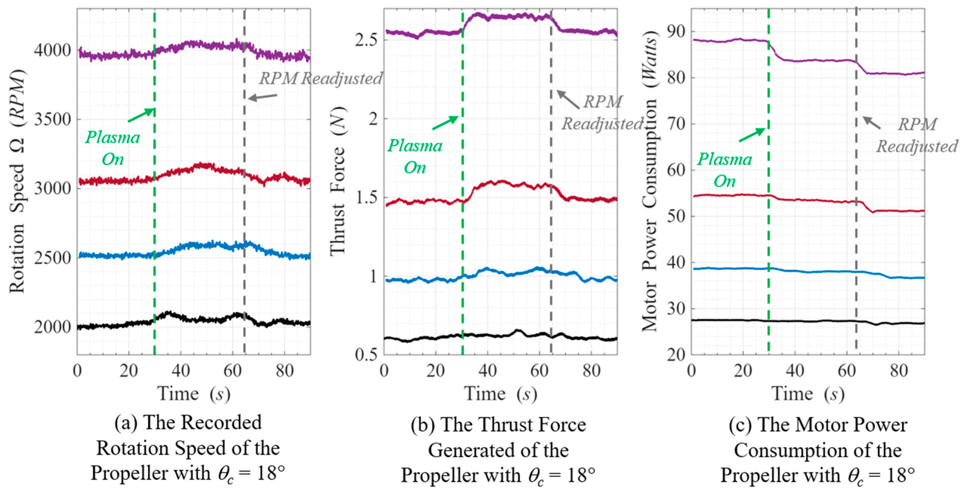
Figure 6 shows the data acquired from the tests conducted on the propeller with θc = 18° in terms of the recorded rotation speed (Figure 6a), thrust force generated by the propeller (Figure 6b) as well as the motor power consumption logged during the test (Figure 6c). For this propeller, four different tests were run with a unique initial rotation speed Ω = 2000, 2500, 3000 and 4000 RPM. As can be clearly seen in the results of the propeller at θc = 18° in Figure 6a), there was an obvious increase of Ω at t~30 s as a direct result of turning on the DBD plasma actuators for all test cases. As mentioned earlier, after the plasma actuation had stabilized, Ω was then brought back down manually to the pre-actuation level while keeping the plasma actuators on as shown clearly in the figure at t~65 s. Alternatively, the actuation effect of increased rotation speed also coincided with a direct increase of the thrust force generated by the propeller model in Figure 6b) due to the combined effects of both increased Ω and flow separation control. While the increase of thrust values seemed minor for the experiments with the lower rotation speed (i.e., Ω = 2000 and 2500 RPM), the magnitude of thrust increase became more apparent for the test with higher rotation speed (i.e., Ω = 3000 and 4000 RPM). After manually bringing the rotation speed down to its pre-actuation level, the thrust generated by the propeller seemed to also go back to their initial pre-actuation values with no significant change as will be presented and discussed later in Table 1.
On the other hand, the most significant change was found in the motor power consumption as can be clearly shown in Figure 6c. Based on the experimental observations, the motor consumption recorded during the experiments decreased noticeably after the plasma actuation was turned on at t~30 s. While the decrease of power consumption was more obvious for the tests with higher rotation speeds (i.e., Ω = 3000 and 4000 RPM), it was consistent through all tests and manifested in parallel to the increase of rotation speed described earlier as a direct result of the decreased drag that was associated with actuation consistent with plasma-induced suppression of separated-flow regions. Moreover, and after bringing the propeller speed back to its pre-actuation value at t~65 s, the motor power consumption was naturally seen to decrease even more, further showcasing the benefits brought to the propeller system as a result of DBD Plasma actuators.
In order to quantify the changes brought by the DBD Plasma actuators on the propeller with the constant pitch angle of θc = 18°, the average values of rotation speed, thrust force and motor power consumption before turning on the actuators and after bringing the rotation speed to its pre-actuation level with the actuators still turned on were calculated and compared in Table 1. The averaged value of thrust and motor power consumption were first converted to non-dimensional form of the thrust and power coefficients using Equations (2) and (3), respectively, where ρ is the density of air, n is the rotation speed in rev/s and D is the propeller diameter in m. All experiments were conducted indoors under controlled laboratory conditions. The air density used in Equations (2) and (3) was calculated assuming standard room conditions (i.e., 22 °C and 101.3 kPa), corresponding to ρ = 1.20 kg/m3. Variations in ambient conditions during testing were negligible. Furthermore, the thrust and power coefficients were then used to calculate the FoM associated with the hovering rotor using Equation (4) to further quantify the efficiency change brought by the actuation effect. It should be noted that the present FoM should be interpreted as a system-level FoM because electrical input power rather than shaft power was measured.
C T = T ρ n 2 D 4
C P = P ρ n 3 D 5
F o M = C T 3 2 2 C P
The results presented in Table 1 clearly demonstrate that, with the rotational speed maintained within ±1% before and after plasma actuation, the power coefficient decreased by up to 7.66%, while the thrust coefficient remained essentially unchanged. The maximum variation in thrust coefficient was less than 0.7%, which is within the experimental variation observed between repeated tests and can also be reasonably attributed to the small residual differences in rotational speed. In contrast, the maximum reduction in power coefficient (7.66%) exceeded the approximately ±2.5% variation observed between repeated tests, indicating that the reduction in power consumption is a repeatable effect of plasma actuation rather than experimental scatter. Consequently, the FoM increased by as much as 9.42%, which also exceeds the experimental variation, demonstrating an improvement in propulsive efficiency without increasing the aerodynamic loading of the blade. The nearly constant thrust coefficient demonstrates that the primary effect of plasma actuation was not to increase blade circulation, but rather to reduce aerodynamic losses [17]. More specifically, the observed reduction in power coefficient indicates that the DBD plasma actuators reduced profile losses associated with boundary-layer separation. By injecting momentum into the near-wall region, the leading-edge plasma actuator energizes the boundary layer, enabling it to better resist the adverse pressure gradient over the suction surface and thereby delaying or reducing the extent of flow separation [18]. As a result, pressure drag acting on the blade is reduced while essentially maintaining the same blade loading, allowing less shaft power to produce the same thrust and leading directly to the observed increase in FoM.
In addition to the quasi-steady momentum introduced by the plasma-induced wall jet, the unsteady nature of DBD plasma actuation may also contribute to the observed aerodynamic improvement [19]. Periodic plasma forcing can introduce disturbances into the separated shear layer, promoting the formation and development of coherent vortical structures [20]. These structures can enhance momentum exchange between the outer flow and the near-wall region, thereby reducing the extent of the separated region and potentially promoting flow reattachment [21]. Such an unsteady mechanism may be particularly relevant when the actuation frequency interacts with the natural instability frequencies of the separated shear layer [22]. In the present experiments, however, the actuation frequency was substantially higher than the propeller rotational frequency, and no phase-resolved flow-field measurements were performed. Therefore, the relative contributions of quasi-steady momentum addition and unsteady vortex excitation cannot be distinguished from the present global performance measurements. Detailed PIV or phase-locked flow-field measurements will be required to clarify the dominant flow-control mechanism.
Unlike a stationary airfoil operating at a fixed angle of attack, each radial station of a rotating propeller experiences a different local Reynolds number and relative flow velocity [23]. Consequently, flow separation is not expected to occur uniformly along the blade span [24], with the lower-Reynolds-number inner blade regions generally being more susceptible to adverse pressure gradients and flow separation [25]. Although direct flow-field measurements were beyond the scope of the present study, the measured reduction in power coefficient is consistent with partial reattachment of these separated regions following plasma actuation. Furthermore, the progressive increase in FoM improvement with increasing rotational speed is consistent with the hypothesis that plasma actuation becomes increasingly effective as blade loading and the associated adverse pressure gradients become more pronounced. While the magnitude of the efficiency improvement observed in the present study is lower than that reported for larger helicopter rotors [13], the comparison should be interpreted carefully because the present propellers operate at substantially higher rotational speeds, much smaller characteristic dimensions, and Reynolds numbers on the order of 104. Under these conditions, the authority of the plasma actuator relative to the characteristic flow velocity is inherently reduced, making the observed efficiency improvements particularly encouraging.

3.2. Further Discussion Based on Experimental Observations

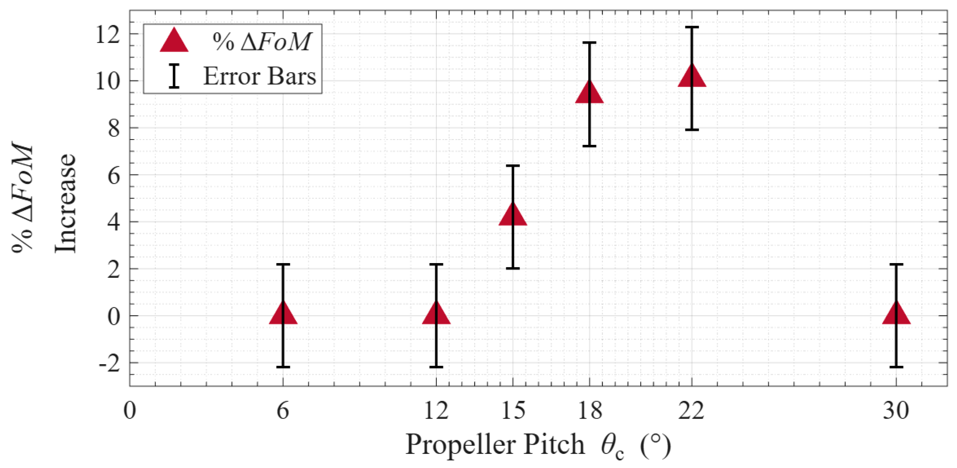
As mentioned earlier, propellers with different θc were tested with actuators to assess their performance enhancement due to plasma actuation. Following the same procedure reported earlier for the propeller θc = 18°, other tests at Ω = 4000 RPM and similar actuation parameters (i.e., Vac and Pac) were conducted for propellers with θc = 6°, 12°, 15°, 18°, 22° and 30° with the percentage change of FoM before and after actuation calculated for each as presented in Figure 7. As reported earlier, the propellers with θc = 6° and 12 showed no change in rotational speed before and after plasma actuation and exhibited no measurable improvement in efficiency. These operating conditions are expected to correspond to predominantly attached flow, leaving little opportunity for plasma-induced boundary-layer control to improve the aerodynamic performance. A 4.2% increase of FoM was first documented for the propeller θc = 15° that consistently increased when a larger pitch propeller was tested up to 10.1% for the propeller with θc = 22°.
The improved performance is likely associated with the development of progressively larger separated-flow regions that the plasma jets remain capable of delaying or partially reattaching, thereby reducing aerodynamic losses. The largest increase in FoM occurred at intermediate blade pitch angles. Under these conditions, the separated-flow region is sufficiently developed for plasma-induced momentum addition to produce significant boundary-layer reattachment, yet not so extensive that complete reattachment becomes increasingly difficult. Consequently, the plasma actuators operate within an optimum regime where relatively small momentum addition produces disproportionately large reductions in aerodynamic losses [16].
On the other hand, no benefits of DBD plasma actuation were seen when a propeller with a much larger pitch angle (i.e., θc = 30°) was tested as shown in Figure 7. Unlike the low-pitch-angle cases, where the baseline flow is expected to remain largely attached, the high-pitch-angle configuration is expected to exhibit substantially stronger flow separation. Nevertheless, increasing the applied actuation voltage beyond the baseline operating condition produced no observable improvement in propeller performance, indicating that increasing the applied voltage alone was insufficient to recover the flow conditions associated with this blade pitch angle. As the pitch angle increases, the baseline flow becomes progressively more susceptible to separation, allowing plasma actuation to improve the propeller performance by delaying or reducing the extent of separated flow [26]. At the highest pitch angles investigated, however, the effectiveness of plasma actuation diminishes. This behavior is consistent with increasingly separated flow under these operating conditions, although direct flow-field measurements were not performed in the present study. Owing to the low Reynolds number regime of the present propeller, where laminar separation, transition, and three-dimensional rotational effects become increasingly important, the precise onset and extent of flow separation cannot be established from the present measurements alone. Future work will combine detailed flow diagnostics and high-fidelity aerodynamic modelling to further investigate the underlying flow physics.
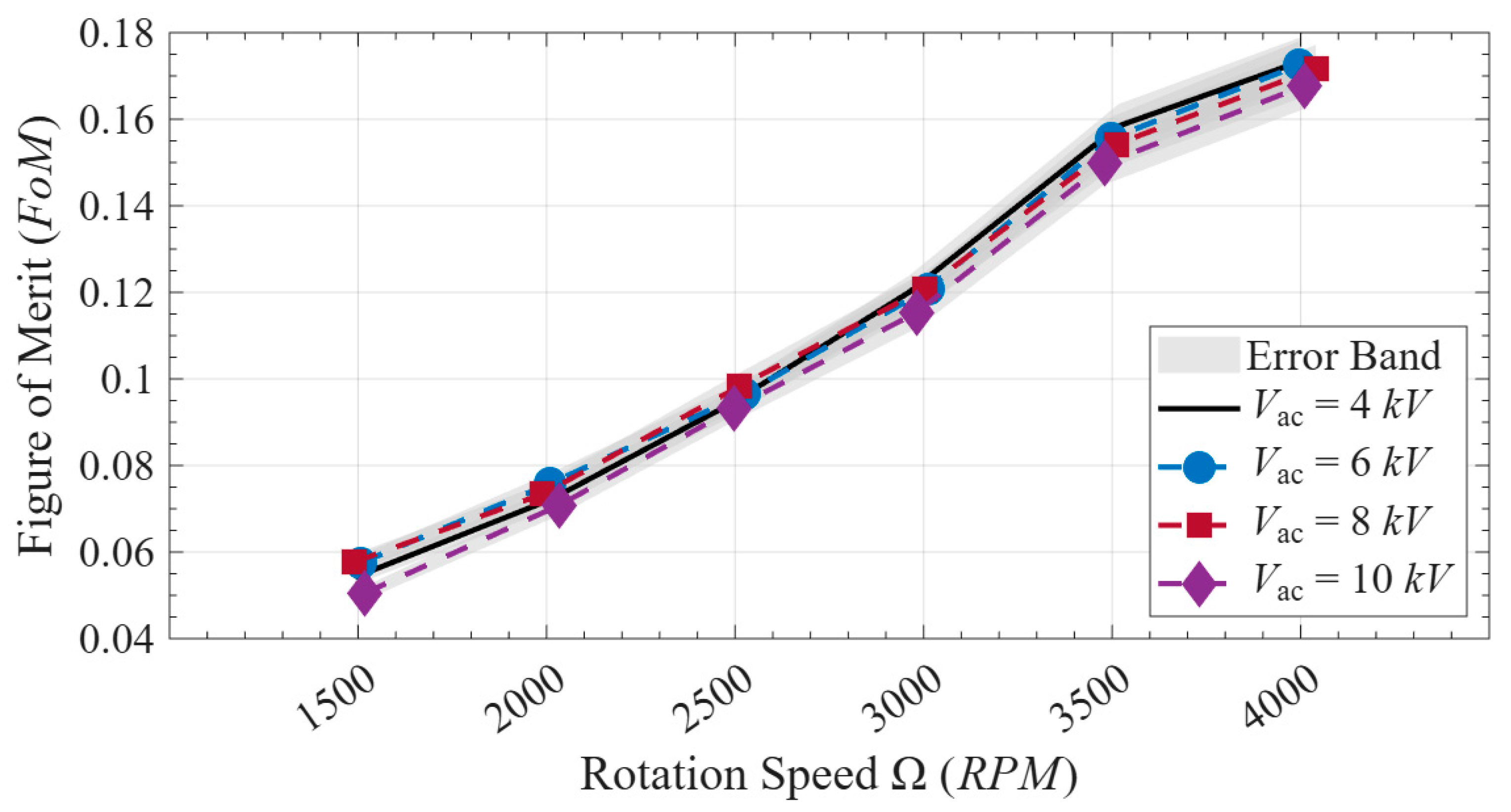
It should also be noted that any increase of applied actuation voltage had no effect on the outcome with regard to the FoM increase before and after actuation. As a matter of fact, plasma was observed to manifest on the sides of the exposed electrodes as early as at Vac = 4 kV, with the purple glow becoming more visually apparent at Vac = 6 kV which was the reason why the previous experiments were conducted at that voltage value. However, and as shown in Figure 8, the final FoM values obtained after turning on the plasma actuators and bringing the propeller back to its pre-actuation value was found to be unchanged when different Vac were used. As clearly shown by the results in the figure, almost the same FoM values were obtained when testing with Vac = 4, 6, 8 or 10 kV and for all tested propeller speeds of Ω = 1500, 2000, 2500, 3000 and 4000 RPM. Within the investigated Vac range, no distinct performance threshold was identified, as the measured FoM remained essentially unchanged with increasing applied voltage. This analysis suggests that once plasma discharge is successfully established, further increases in applied voltage do not necessarily produce proportional increases in aerodynamic performance. Instead, the present results suggest the existence of a saturation regime in which sufficient momentum is already being transferred to the near-wall flow to achieve the maximum attainable reduction in separated-flow losses for the tested operating conditions. Additional electrical power therefore provides diminishing aerodynamic returns.
Furthermore, it had been reported earlier that the actuation frequency fac plays an important role in earlier studies on the rotor performance enhancement [12,13], especially for fac within an order of magnitude of the rotation frequency of the propeller (i.e., fr = Ω/60). However, due to hardware limitations of the plasma generator and the DBD plasma actuators physical geometry, the fac could not be controlled in this study beyond a range of 4 ≤ fac ≤ 7 kHz, which was much higher than the used fr (i.e., fr = Ω/60 = 66.67 Hz << fac). Nevertheless, insignificant changes to rotor performance enhancement are expected in such cases [13] and the gains obtained in this study are thought to be the highest possible within the current experimental scope.
From a practical perspective, the present findings highlight the potential of DBD plasma actuators as a lightweight active flow-control technology for electrically powered UAVs, where propulsion efficiency directly influences flight endurance and mission capability. Although the measured improvements in FoM are modest, even relatively small reductions in propeller power consumption can translate into meaningful extensions in flight time without increasing battery capacity or vehicle weight. Several limitations of the present study should nevertheless be acknowledged. The aerodynamic benefits of plasma actuation were inferred indirectly from measured changes in propeller performance, while direct flow-field measurements such as Particle Image Velocimetry (PIV) were beyond the scope of this investigation. Furthermore, only a single leading-edge actuator configuration, one propeller geometry, and hovering operating conditions were considered. Future work should therefore focus on detailed flow visualization to directly characterize the separation and reattachment mechanisms, systematic optimization of actuator geometry and placement, and extension of the methodology to more realistic forward-flight conditions and additional propeller designs. Despite these limitations, the present results demonstrate that DBD plasma actuators offer a promising approach for improving the aerodynamic efficiency of tested UAV propellers operating in separated-flow regimes while requiring minimal additional system complexity.


4. Conclusions

An experimental study was conducted to evaluate the effects of using dielectric barrier discharge (DBD) plasma actuators for flow separation control on a small rotating UAV propeller blades under hovering conditions. The investigation focused on small-scale propellers operating at relatively high rotational speeds, a regime that has received limited attention in previous plasma-based flow-control studies.
The DBD plasma actuators of this study were positioned along the leading edge of the tested propeller blades and used for tests with different rotation speeds and blade pitch angles. Performance improvements were interpreted as being consistent with mitigation of separated-flow regions, with measurable benefits first observed for blade pitch angles of 15° and above. Plasma activation resulted in a reduction in motor power consumption while maintaining nearly constant thrust, consistent with a reduction in aerodynamic losses associated with separated flow. The thrust coefficient remained essentially unchanged before and after actuation, whereas the power coefficient decreased by up to approximately 8%. Consequently, the propeller FoM increased by as much as about 9%, demonstrating a clear improvement in aerodynamic efficiency attributable to plasma actuation. A parametric assessment further revealed that the effectiveness of plasma actuation appears to depend on the degree of flow separation in the baseline flow, with no measurable benefits observed at the highest blade pitch angle tested, where the baseline flow is expected to be increasingly separated.
Within the tested range, variations in actuation voltage did not produce noticeable differences in performance, and the actuation frequency remained much higher than the propeller rotational frequency. These preliminary findings suggest that the observed flow-control effect was primarily associated with quasi-steady momentum injection rather than frequency-synchronized actuation, although further investigation is required especially for much lower actuation frequencies, particularly through detailed flow-field measurements and at lower actuation frequencies.
Overall, the present results demonstrate the potential of DBD plasma actuators as an active flow-control approach for improving the efficiency of the tested small-scale UAV propeller operating within the investigated range of blade pitch angles and rotational speeds. The present work demonstrates that plasma-based active flow control can provide measurable propulsive efficiency improvements for small UAV propellers without introducing moving components or significant additional system weight. These findings support further investigation of plasma-assisted propulsion concepts for next-generation electric UAV platforms. The findings provide a foundation for future studies involving detailed flow-field measurements such as PIV to reveal the flow separation regimes associated with the propeller, optimized actuator configurations, and extension to more realistic operating conditions.

Author Contributions

A.S., K.B. and H.H.; Methodology, A.S.; Validation, A.S., K.B., H.S. and H.H.; Formal analysis, A.S., H.S. and A.D.; Investigation, A.S., K.B., H.S. and A.D.; Resources, H.H.; Data curation, A.S., K.B., H.S. and A.D.; Writing, original draft, A.S.; Writing, review and editing, A.S. and H.H.; Supervision, H.H.; Project administration, H.H.; Funding acquisition, H.H. All authors have read and agreed to the published version of the manuscript.

Funding

The research work is partially supported by the Army Research Office (ARO) under the contract number of W911NF2410251 and the National Science Foundation (NSF) under the award numbers of CBET-1935363 and CBET-2313310.

Data Availability Statement

Data available upon request.

Acknowledgments

The authors want to thank James Benson and Andrew Jordan of Iowa State University for their help in assembling the experimental test stand of this study.

Conflicts of Interest

The authors declare no conflict of interest.

References

  1. Ebrahimi, A.; Hajipour, M. Flow separation control over an airfoil using dual excitation of DBD plasma actuators. Aerosp. Sci. Technol. 2018, 79, 658–668. [Google Scholar] [CrossRef] [Scilit]
  2. Corke, T.C.; Post, M.L.; Orlov, D.M. Single dielectric barrier discharge plasma enhanced aerodynamics: Physics, modeling and applications. Exp. Fluids 2008, 46, 1–26. [Google Scholar] [CrossRef] [Scilit]
  3. Roth, J.R.; Sherman, D.M.; Wilkinson, S.P. Boundary layer flow control with a one atmosphere uniform glow discharge surface plasma. In Proceedings of the 36th AIAA Aerospace Sciences Meeting and Exhibition, Reno, NV, USA, 12–15 January 1998; American Institute of Aeronautics and Astronautics Inc., AIAA: Reno, NV, USA, 1998. [Google Scholar] [CrossRef] [Scilit]
  4. Zheng, J.G.; Cui, Y.D.; Zhao, Z.J.; Li, J.; Khoo, B.C. Investigation of airfoil leading edge separation control with nanosecond plasma actuator. Phys. Rev. Fluids 2016, 1, 073501. [Google Scholar] [CrossRef] [Scilit]
  5. Roupassov, D.V.; Nikipelov, A.A.; Nudnova, M.M.; Starikovskii, A.Y. Flow Separation Control by Plasma Actuator with Nanosecond Pulsed-Periodic Discharge. AIAA J. 2012, 47, 168–185. [Google Scholar] [CrossRef] [Scilit]
  6. Samad, A.; Bowers, K.; Sista, H.; Dhulipalla, A.; Hu, H. An Exploratory Study on the Use of Dielectric Barrier Discharge Plasma Actuators for Icing Control of UAV Propellers. In Proceedings of the AIAA Aviation Forum and ASCEND, Las Vegas, NV, USA, 21–25 July 2025; American Institute of Aeronautics and Astronautics Inc., AIAA: Las Vegas, NV, USA, 2025. [Google Scholar] [CrossRef] [Scilit]
  7. Dawson, R.; Little, J. Characterization of nanosecond pulse driven dielectric barrier discharge plasma actuators for aerodynamic flow control. In Proceedings of the 6th AIAA Flow Control Conference, New Orleans, LA, USA, 25–28 June 2012; American Institute of Aeronautics and Astronautics Inc.: New Orleans, LA, USA, 2012. [Google Scholar] [CrossRef] [Scilit]
  8. Moreau, E. Airflow control by non-thermal plasma actuators. J. Phys. D Appl. Phys. 2007, 40, 605. [Google Scholar] [CrossRef] [Scilit]
  9. Forte, M.; Jolibois, J.; Pons, J.; Moreau, E.; Touchard, G.; Cazalens, M. Optimization of a dielectric barrier discharge actuator by stationary and non-stationary measurements of the induced flow velocity: Application to airflow control. Exp. Fluids 2007, 43, 917–928. [Google Scholar] [CrossRef] [Scilit]
  10. Dawson, R.; Little, J. Characterization of nanosecond pulse driven dielectric barrier discharge plasma actuators for aerodynamic flow control. J. Appl. Phys. 2013, 113, 103302. [Google Scholar] [CrossRef] [Scilit]
  11. Starikovskiy, A.; Persikov, N.; Miles, R. Helicopter lift force increase in hover mode by NS-SDBD plasma actuators. In Proceedings of the AIAA Aerospace Sciences Meeting, Kissimmee, FL, USA, 8–12 January 2018; American Institute of Aeronautics and Astronautics Inc., AIAA: Kissimmee, FL, USA, 2018. [Google Scholar] [CrossRef] [Scilit]
  12. Zhao, G.; Wang, C.; Yang, Y.; Li, G.; Shi, Z. Rotor performance enhancement by alternating current dielectric barrier discharge plasma actuation. Plasma Sci. Technol. 2022, 25, 015506. [Google Scholar] [CrossRef] [Scilit]
  13. Polonsky, D.; Keisar, D.; Greenblatt, D. Rotor Performance Enhancement Using Pulsed Plasma Actuation. AIAA J. 2021, 59, 3275–3280. [Google Scholar] [CrossRef] [Scilit]
  14. Polonsky, D.; Stalnov, O.; Greenblatt, D. Noise Reduction on a Model Helicopter Rotor Using Dielectric Barrier Discharge Plasma Actuators. AIAA J. 2023, 61, 3134–3141. [Google Scholar] [CrossRef] [Scilit]
  15. Samad, A.; Dhulipalla, A.; Hu, H. An experimental study to evaluate the effectiveness of a Rotor-Integrated-Heating system for UAV inflight icing protection. Exp. Therm. Fluid Sci. 2025, 166, 111485. [Google Scholar] [CrossRef] [Scilit]
  16. Wei, B.; Wu, Y.; Liang, H.; Su, Z.; Li, Y. Flow control on a high-lift wing with microsecond pulsed surface dielectric barrier discharge actuator. Aerosp. Sci. Technol. 2020, 96, 105584. [Google Scholar] [CrossRef] [Scilit]
  17. Corke, T.C.; Enloe, C.L.; Wilkinson, S.P. Dielectric barrier discharge plasma actuators for flow control. Annu. Rev. Fluid Mech. 2010, 42, 505–529. [Google Scholar] [CrossRef] [Scilit]
  18. Aono, H.; Fukumoto, H.; Abe, Y.; Sato, M.; Nonomura, T.; Fujii, K. Separated Flow Control of Small Horizontal-Axis Wind Turbine Blades Using Dielectric Barrier Discharge Plasma Actuators. Energies 2020, 13, 1218. [Google Scholar] [CrossRef] [Scilit]
  19. Aono, H.; Kawai, S.; Nonomura, T.; Sato, M.; Fujii, K.; Okada, K. Plasma-Actuator Burst-Mode Frequency Effects on Leading-Edge Flow-Separation Control at Reynolds Number 2.6 × 10⁵. AIAA J. 2017, 55, 3789–3806. [Google Scholar] [CrossRef] [Scilit]
  20. Koide, Y.; Sasaki, R.; Kameya, Y.; Motosuke, M. A burst wave-induced plasma actuator for controlling separated flow over a backward-facing step at low Reynolds numbers. Exp. Therm. Fluid Sci. 2015, 66, 72–78. [Google Scholar] [CrossRef] [Scilit]
  21. Sato, M.; Okada, K.; Asada, K.; Aono, H.; Nonomura, T.; Fujii, K. Unified mechanisms for separation control around airfoil using plasma actuator with burst actuation over Reynolds number range of 103–106. Phys. Fluids 2020, 32, 025102. [Google Scholar] [CrossRef] [Scilit]
  22. Zhang, P.; Dai, C.; Liu, A.; Wang, J. The effect of actuation frequency on the plasma synthetic jet. Sci. China Technol. Sci. 2011, 54, 2945–2950. [Google Scholar] [CrossRef] [Scilit]
  23. Leishman, G. Principles of Helicopter Aerodynamics, 2nd ed.; Cambridge University Press: Cambridge, UK, 2006. [Google Scholar]
  24. Tsung, F.-L.; Sankar, L. Numerical Simulation of Flow Separation for Rotors and Fixed Wings; American Institute of Aeronautics and Astronautics, Inc.: Reston, VA, USA, 1992. [Google Scholar] [CrossRef] [Scilit]
  25. Yu, H.; Zheng, J. Investigation of flow separation and its control over rotor blades in forward flight with plasma actuator. Int. J. Heat Mass Transf. 2025, 245, 127023. [Google Scholar] [CrossRef] [Scilit]
  26. Zhu, Z.; Fradera-Soler, P.; Zhu, Y.; Liu, F. Numerical investigation of flow induced by plasma actuators around a circular cylinder in quiescent air under duty-cycle actuation. Comput. Fluids 2026, 306, 106953. [Google Scholar] [CrossRef] [Scilit]
Figure 1. Schematic of a typical DBD plasma actuator.
Aerospace 13 00668 g001
Figure 2. The propeller model used in this study.
Aerospace 13 00668 g002
Figure 3. A schematic of the experimental test stand used in this study.
Aerospace 13 00668 g003
Figure 4. (a) A schematic of the DBD plasma actuators used in this work & (b) example of plasma generation over static propeller.
Aerospace 13 00668 g004
Figure 5. An example of the recorded voltage & current supplied to the DBD plasma actuators.
Aerospace 13 00668 g005
Figure 6. Results of the Experiments Done on the Propeller Equipped with DBD Plasma Actuators with θc = 18°.
Aerospace 13 00668 g006
Figure 7. Results of FoM percentage increase before & after actuation for different pitch angles.
Aerospace 13 00668 g007
Figure 8. Calculated FoM values for tests with different actuation voltages at θc = 18°.
Aerospace 13 00668 g008
Table 1. Percentage change of aerodynamic parameters before & after plasma actuation & RPM adjustment for the blades with θc = 18°.
Test at
2000 RPM
Test at
2500 RPM
Test at
3000 RPM
Test at
4000 RPM
RPM0.49%0.69%0.81%0.35%
CT−0.46%0.91%0.16%0.69%
CP−2.43%−4.85%−7.17%−7.66%
FoM4.72%6.54%7.98%9.42%
Disclaimer/Publisher’s Note: The statements, opinions and data contained in all publications are solely those of the individual author(s) and contributor(s) and not of MDPI and/or the editor(s). MDPI and/or the editor(s) disclaim responsibility for any injury to people or property resulting from any ideas, methods, instructions or products referred to in the content.