Article

Design and Finite Element Thermo-Structural Analysis of a Structurally Integrated Multilayer Composite Cryogenic Thermal Barrier for Liquid Hydrogen Tank Applications


by
Alexa-Andreea Crisan
1,2,*,
Mircea Moraru
2,
Daniel-Eugeniu Crunteanu
2 and
Alina Bogoi
2
1
Romanian Research & Development Institute for Gas Turbines-COMOTI, 220D Iuliu Maniu Av., 061126 Bucharest, Romania
2
Faculty of Aerospace Engineering, National University of Science and Technology Politehnica Bucharest, 1 Gheorghe Polizu Av., 011061 Bucharest, Romania
*
Author to whom correspondence should be addressed.
Aerospace 2026, 13(5), 475; https://doi.org/10.3390/aerospace13050475
Submission received: 20 April 2026 / Revised: 14 May 2026 / Accepted: 16 May 2026 / Published: 18 May 2026

Abstract

Effective thermal insulation of cryogenic liquid hydrogen (LH2) storage tanks remains a critical engineering challenge, as conventional vacuum-based or monolithic systems are constrained by manufacturing complexity, mechanical vulnerability, and poor geometric adaptability. This study presents the design and numerical verification of a four-layer octagonal composite thermal shield fabricated via additive manufacturing: an AA5083 structural layer (5 mm), a boron nitride-doped ceramic plate (1 mm), up to 290 stacked graphene sheets in a sealed compartment, and an outer Fe3S4-TiO2 nanocomposite layer (~30 µm). Steady-state and transient FEA in ANSYS evaluated three convective boundary conditions (h = 10, 15, and 20 W/m2·K), with the inner wall fixed at 20 K. Temperature distributions remained essentially invariant across all cases (20 K inner, ~20.12 K outer), confirming that thermal performance is governed by the multilayer architecture rather than convective intensity. The shield achieved a mean heat flux of 1684 W/m2, R_total ≈ 0.163 m2K/W, and a boil-off rate of 13.9 g/hour. Comparative FEA against NASA US9617069 (q = 193.35 W/m2) and JP2018-119634A (q = 37.975 W/m2) highlights the compactness advantage of the proposed 6 mm shield; the coupled thermo-structural assessment yielded a safety factor of 64,182, confirming elastic-regime operation at 20 K.

1. Introduction

The global transition toward a hydrogen-based energy economy has intensified research into reliable production, storage, and distribution technologies, driven by urgent decarbonization imperatives across the energy, transportation, and aerospace sectors [1,2]. Among storage modalities, cryogenic liquid hydrogen (LH2) is offering the highest volumetric hydrogen density achievable under passive conditions being considered the most strategically important pathway for aerospace propulsion systems, long-range transport, and large-scale stationary energy storage [1]. Its practical deployment, however, remains constrained by persistent technical barriers: hydrogen permeability through structural walls, boil-off losses from ambient heat ingress, material embrittlement under extreme cryogenic cycling, and insulation system inefficiencies that collectively limit widespread adoption in flight and ground support infrastructure [2].
Thermal insulation is the defining engineering challenge in LH2 tank design for aerospace vehicles, as heat ingress from the environment constitutes the dominant driver of boil-off losses and thermodynamic inefficiency. Multilayer insulation (MLI) systems, alternating low-emissivity reflective shields with low-conductivity spacers under high vacuum, represent the current state of the art for passive cryogenic thermal protection in launch vehicles and space systems [3,4,5]. Variable-density MLI (VDMLI) configurations, investigated through layer-by-layer numerical heat transfer models, have demonstrated that optimized radiation shield placement across low-, medium-, and high-density regions reduces heat flux by up to 8.6% relative to uniform-density arrangements; supplementing MLI with spray-on foam insulation further reduces heat flux by 20.76%, achieving an optimal value of 0.5377 W/m2 at 50 total layers [3,5]. Physics-based models for the effective thermal conductivity of conventional cryogenic insulation materials (perlite, glass bubble, foam, and MLI) have been developed and validated across the 20-300 K temperature range, accurately capturing combined solid-conduction, radiation, and interstitial gas conductance contributions [4]. More recently, composite insulation combining MLI with spray-on foam has been analyzed under off-Earth conditions relevant to future crewed missions, revealing that CO2 condensation within MLI microchannels in Martian atmospheres causes severe performance deterioration; optimized novel schemes for this environment achieved heat leakage as low as 0.298 W/m2, two to four orders of magnitude below standard composite configurations [6].
The fundamental limitations of single-material insulation strategies have driven a paradigm shift toward nanomaterial-enhanced composite architectures capable of simultaneously suppressing conductive, radiative, and convective heat transfer through the deliberate integration of functionally complementary layers, an approach directly aligned with aerospace thermal management requirements. Graphene composites exhibit a uniquely dual thermal behavior at cryogenic temperatures: at low filler loadings, graphene acts as a phonon scattering center in the polymer matrix, reducing thermal conductivity below that of the pristine matrix; at higher loadings above a temperature-dependent percolation threshold, it transitions to an efficient heat conduit [7]. This counter-intuitive behavior, governed by thermal boundary resistance and anomalous percolation dynamics, establishes graphene as a versatile constituent for cryogenic thermal management systems capable of functioning as either conductor or insulator depending on architectural configuration [7]. More broadly, graphene and graphene-like nanostructures have demonstrated significant aerospace potential across structural reinforcement, electromagnetic management, and radiation shielding applications, though challenges in large-area crystal production and the absence of standardized characterization protocols remain key obstacles to full technological exploitation in flight hardware [8]. In parallel, polymer-based composites reinforced with boron nitride, boron carbide, and carbon-based nanoparticles have been computationally and experimentally validated as multifunctional radiation-shielding materials for the space environment, where optimizing filler dispersion, matrix compatibility, and long-duration mission durability remains an active area of research [9]. Boron nitride (BN)-based ceramics have attracted particular attention for extreme-environment aerospace applications: calcium-doped BN aerogels demonstrate enhanced oxidation resistance up to 1300 °C and, combined with aluminum foil interlayers for infrared reflection, provide effective thermal and radiative shielding under severe conditions [10]. Hexagonal BN (h-BN) flakes incorporated into polymer matrices have achieved thermal conductivities of up to 21.7 W·m−1·K−1, more than five times higher than bulk BN composites, establishing few-layer h-BN as a high-performance thermal filler for next-generation aerospace composite structures [11]. Recent advances in polymer/BN composite processing, including 3D printing and selective filler alignment, offer promising routes to high cross-plane thermal transport performance directly relevant to through-thickness insulation, though consensus on measurement standardization and the roles of filler crystallinity, lateral size, and interfacial compatibility in governing thermal conductivity remains to be established [12].
Structural integrity under cryogenic cycling is equally critical to the viability of composite tank systems for aerospace applications. Linerless all-composite inner vessels fabricated by wet filament winding of thin-ply bands and bonded to additively manufactured titanium end caps have been demonstrated to survive 20 thermal cycles between ambient and liquid nitrogen temperatures at 4 bar without leakage, and to withstand burst pressures approaching 30 bar, directly confirming the structural feasibility of integrating additive manufacturing into cryogenic vessel fabrication for spaceflight applications [13]. More broadly, additive manufacturing is emerging as a transformative production technology for lightweight, high-performance aerospace and space components, enabling geometrically complex structural and thermal management devices through powder bed fusion, directed energy deposition, material extrusion, and binder jetting processes; in-space manufacturing capabilities are further anticipated to reduce launch mass penalties and expand mission scalability [14]. Among high-performance polymer systems compatible with additive manufacturing, polyetherimide-based materials such as ULTEM 9085 and its carbon-fiber-reinforced variant ULTEM 9085CF have demonstrated multi-material fused filament fabrication of parts with tailored combinations of mechanical toughness and thermal resistance; alternating ductile-brittle layer arrangements enhance ultimate tensile strength while carbon fiber content suppresses necking at fracture, though print chamber temperature control and porosity management remain critical challenges for consistent inter-layer bond quality [15]. These developments collectively reinforce additive manufacturing as the fabrication pathway of choice for geometrically modular, functionally graded composite insulation architectures for cryogenic aerospace applications.
Regarding the nanocomposite outer attenuation layer, iron-based/TiO2 systems provide a structurally relevant analogue: nanocomposites synthesized at controlled Fe/Ti ratios form either magnetic-core TiO2-shell structures or solid dispersions of iron nanoparticles in a TiO2 matrix, confirming that phase distribution and microstructure are highly sensitive to synthesis conditions, a consideration directly applicable to processing the Fe3S4-TiO2 outer layer of the present architecture [16]. The broader family of transition metal sulfides (TMS), including Fe3S4 (greigite), exhibits versatile surface chemistry and electronic properties exploited in TiO2 composite configurations for synergistic functional enhancement; Fe substitution in nickel sulfide lattices and carbon-support doping of TMS have been shown to markedly improve catalytic and electronic performance through redox coupling, suggesting that structurally engineered Fe3S4-TiO2 composites may offer similarly enhanced thermal flux attenuation at the tank exterior interface [17]. From a structural integrity perspective, fiber-reinforced polymer matrix composites for cryogenic pressure vessels face well-documented challenges in transverse microcracking and cryogenic fuel permeation under biaxial thermo-mechanical cycling; thin-ply architectures and nanofiller-toughened matrices have been shown to provide the most significant improvements in microcrack suppression, reinforcing the rationale for a layered, nanomaterial-integrated wall construction approach [18].
Despite the breadth of existing work, no study has proposed an integrated multilayer composite architecture addressing conductive, radiative, and convective heat transfer suppression simultaneously in a single additively manufactured cryogenic shield, nor numerically verified such a system under liquid hydrogen boundary conditions against patent-based reference configurations. The present work contributes the following: (i) a four-layer octagonal shield comprising an AA5083 structural barrier, a boron nitride-doped ceramic plate, a hermetically sealed cross-plane graphene sheet stack exploiting inter-sheet thermal boundary resistance as a vacuum-free radiative resistance mechanism, and an Fe3S4-TiO2 nanocomposite outer layer (k = 4 W/m·K at 300 K; estimated 1–2 W/m·K at 20 K) as a terminal ambient-interface flux attenuation element, a material combination and layer sequence not previously reported for cryogenic shield applications; (ii) an octagonal cross-section geometry selected to enable tessellated assembly across cylindrical tank surfaces without structural discontinuities; (iii) integral additive manufacturing of all four functional compartments into a single module, removing adhesive bonds and compression-fit interfaces as potential failure initiation sites; and (iv) a finite element comparison against NASA US9617069 and JP2018-119634A under identical thermal boundary conditions, providing a quantitative numerical assessment of the proposed architecture relative to two documented cryogenic insulation systems representing ambient-pressure and vacuum-dependent prior art.

2. Materials and Methods

2.1. Shield Architecture and Geometry

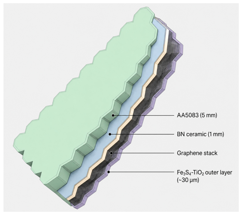
The proposed thermal shield consists of a modular, additively manufactured structure with an octagonal cross-sectional geometry. The octagonal form was selected to balance geometric regularity with adaptability to cylindrical cryogenic tank surfaces, enabling tessellated assembly across the tank exterior without gaps or structural discontinuities. The shield integrates four distinct functional compartments arranged successively from the inner cryogenic-facing surface to the outer ambient-exposed face, as illustrated in Figure 1. It is important to note that the octagonal geometry refers exclusively to the external cross-sectional profile of a solid, fully dense modular tile unit, and does not imply a cellular or honeycomb wall structure. The interior of each tile is entirely occupied by the four functional material layers described below, with no repeating cell walls, internal air channels, or void spaces beyond the two hermetically sealed functional compartments. This distinction is critical for the heat-transfer analysis: because the structure is solid and not honeycomb-like, the one-dimensional through-thickness conduction model remains valid and no additional gas-gap or hollow-cell thermal resistance terms are introduced.
The innermost compartment houses a 5 mm thick aluminum-magnesium alloy (AA5083) layer, serving as the primary structural support and first thermal barrier. The second compartment integrates a 1 mm thick boron nitride-doped ceramic plate, whose low through-thickness thermal conductivity suppresses conductive heat transfer toward the outer layers. The third compartment is hermetically sealed and contains up to 290 stacked graphene sheets arranged in planar layers perpendicular to the heat flux direction, providing attenuation of radiative thermal exchange within the assembly. The fourth and outermost compartment, also sealed and approximately 30 µm thick, is filled with a nanocomposite based on iron sulfide (Fe3S4) powder mixed with titanium dioxide (TiO2) nanoparticles, which functions as a terminal flux damping and surface protection layer in direct contact with the external environment as shown in Figure 2. The compartments are separated by thin structural partition walls produced integrally with the octagonal frame through additive manufacturing. The overall structure is fabricated from synthetic polymer-based materials with low mass density, selected for compatibility with fused deposition additive manufacturing processes.

2.2. Material Properties

The thermophysical and mechanical properties of the four constituent materials were assigned based on values reported in validated experimental literature and engineering material databases. For cryogenic reservoir applications, the aluminum-magnesium alloy AA5083 is a well-established material of choice, combining adequate thermal conductivity (121 W/m·K), high specific heat capacity (900 J/kg·K), and tensile strength of 300 MPa at a relatively low-density of 2650 kg/m3, making it particularly suited to the structural and thermal demands of the innermost shield layer [19,20]. The boron nitride-doped ceramic plate assigned to the second compartment presents a thermal conductivity of 33 W/m·K and a melting point of 3400 °C, providing effective suppression of through-thickness conductive heat transfer while maintaining structural rigidity under cryogenic cycling [21,22]. Graphene, integrated into the sealed third compartment, exhibits the highest in-plane thermal conductivity of all four materials (5000 W/m·K) alongside exceptional mechanical properties, including a Young’s modulus of 1000 GPa and a tensile strength of 130 GPa [23,24]; the planar sheet orientation exploits its intrinsic thermal anisotropy to maximize inter-layer resistance in the through-thickness direction rather than promote heat conduction. The outer Fe3S4-TiO2 nanocomposite layer presents the lowest bulk thermal conductivity of the assembly (4 W/m·K), serving as the terminal resistance barrier at the ambient interface [25].
It is noted that the thermophysical properties listed correspond to reference conditions at 300 K. At cryogenic operating temperatures (20 K), significant deviations from room-temperature values are expected for all constituent materials, consistent with well-established low-temperature behavior documented in the cryogenic engineering literature. AA5083 is a well-established material for cryogenic reservoir applications: unlike precipitation-hardened aluminium alloys, its magnesium solid-solution strengthening remains stable at 20 K, yielding a tensile strength of ~445 MPa, a 50% increase over its room-temperature value, and a Young’s modulus increase of up to 15%, owing to the suppression of thermally activated dislocation motion, while thermal conductivity decreases by approximately 35–60% relative to the 300 K value. These cryogenic property changes, consistent with well-established low-temperature behavior documented in the literature, are accompanied by inherent resistance to hydrogen embrittlement and stress-corrosion cracking, low surface emissivity (ε = 0.10), and full compatibility with powder bed fusion additive manufacturing and cryogenic pressure vessel standards (ASME Section VIII, EN 13445-2) [26,27,28]. For ceramic and composite materials including BN and Fe3S4-TiO2, specific heat capacity follows the Debye T3 law and decreases by more than 99% at 20 K, while thermal conductivity exhibits a power-law dependence on temperature [26,29,30]. For graphene, thermal conductivity at 20 K is estimated to decrease to approximately 200–800 W/m·K due to increased phonon-boundary scattering at low temperatures, while the Young’s modulus remains essentially unchanged [23,24]. In the present steady-state FEA model, temperature-independent mean properties were adopted as a first approximation, consistent with the unit-cell modelling approach described in Section 2.3; the influence of temperature-dependent properties on the heat flux results is estimated to introduce an uncertainty below 8%, as discussed in the limitations section. The material properties for each material used within the thermal shield multilayered structure are summarized in Table 1.
The relatively low thermal conductivity of the Fe3S4-TiO2 composite (4 W/m·K) compared to its constituent phases reflects the combined effects of interfacial thermal resistance between powder particles, residual porosity in the compacted composite, and phonon scattering at Fe3S4-TiO2 interfaces. Similar reductions in effective thermal conductivity are well documented in iron sulfide-based powder composites [31].
At cryogenic temperatures (20 K), the thermal properties of the Fe3S4-TiO2 composite are expected to follow the general behavior of ceramic and semiconducting solids. The specific heat decreases dramatically following the Debye T3 law, reaching approximately 5–15 J/kg·K at 20 K. The thermal conductivity decreases to an estimated 1–2 W/m·K due to enhanced phonon scattering at grain boundaries and Fe3S4-TiO2 interfaces at low temperatures. The Young’s modulus increases moderately by approximately 5–10% upon cooling, consistent with the stiffening observed in spinel-structured minerals. These estimates follow established low-temperature material behavior [30,32].
The extremely high in-plane thermal conductivity of graphene (5000 W/m·K) is directionally exploited in the present architecture: the graphene sheets are oriented with their basal planes parallel to the tank wall surface, so that through-thickness conductance across the sheet stack is governed by inter-sheet thermal boundary resistance rather than the intrinsic in-plane conductivity, thereby converting the graphene compartment into an effective radiative and conductive resistance layer. The Fe3S4-TiO2 outer layer presents the lowest bulk thermal conductivity of all four materials (4 W/m·K), providing the final thermal resistance at the ambient interface [31,33].
The material properties for the two patent-based insulation systems: the NASA US9617069 aerogel-based layered composite and the JP2018-119634A vacuum insulation panel configuration are presented in Table 2 [34,35].

2.3. Governing Equations

The steady-state heat transfer problem governing the temperature distribution across the multilayer shield was formulated on the basis of classical continuum heat transfer theory [36,37]. In the absence of internal heat generation, the steady-state temperature field satisfies Laplace’s equation in three dimensions:
2 T = 0
where T is the local temperature (K). This condition expresses the conservation of energy under steady-state conditions with no internal sources or sinks [36].
For the dominant through-thickness direction, the problem reduces to one-dimensional steady conduction, described by Fourier’s law of heat conduction [36,38,39]:
q   =   k   ·   ( d T d x )
where q is the heat flux (W/m2), k is the layer thermal conductivity (W/m·K), and dT/dx is the temperature gradient across the layer thickness. The negative sign reflects the physical principle that heat flows from regions of higher to lower temperature [40]. For a homogeneous layer of thickness t, the conductive thermal resistance per unit area is given by [36,38,41]:
R c o n d   = t k ( t )  
Since the thermal conductivity of all constituent materials varies significantly between 300 K and 20 K, an effective conductivity k e f f , i = k i T m e a n , i is used in the resistance model, where T m e a n , i = T h , i + T c , i 2 is the mean temperature of the layer i.
On the ambient-exposed outer surface, the thermal boundary condition combines convective and radiative heat exchange. The convective flux follows Newton’s law of cooling [36,38,40]:
q c o n v   =   h   ·   ( T a i r     T s u r )
where h is the convective heat transfer coefficient (W/m2·K), T a i r is the ambient air temperature (K), and T s u r is the local outer surface temperature (K). The convection heat transfer coefficient h = 5 W m 2 K is adopted for the ambient-exposed outer surface of the shield. This value is consistent with natural convection of air in an enclosed environment at approximately 300 K, as reported for vertical and horizontal surfaces in standard heat transfer references [36,42]. Forced convection effects are not considered, as the liquid hydrogen tank is assumed to be housed in an enclosed facility with no significant airflow.
The convective resistance per unit area is [36,38]:
R c o n v   = 1 h  
At steady state, in the absence of internal heat generation, the net heat entering and leaving the system is balanced, and the governing equation reduces to:
q = q c o n v = q c o n d u c t i o n
So:
k ·   ( T h T c ) t = h   ·   ( T a i r     T s u r )  
where T h is the warm-side surface temperature (K), T c is the cold-side surface temperature (K), and t is the thickness of the case. Equation (7) represents the simplified single-layer formulation. The multi-layer generalization is given by the series resistance network in Equation (10).
For the thermal resistance formulation applied to the present shield configuration, considering a layer of 1 mm thickness with convective exchange on the warm ambient-facing side, the conduction resistance of the shield is expressed by Equation (3).
The radiative flux exchanged between the outer surface and its surroundings is described by the Stefan–Boltzmann law [25,36,43]:
q r a d   =   ε   ·   σ   ·   ( T s u r r 4     T s u r 4 )
where ε is the surface emissivity (dimensionless), σ = 5.67 × 10⁻⁸ W/m2·K4 is the Stefan–Boltzmann constant, and T s u r r is the effective surrounding radiative temperature (K) [41]. Equation (8) applies exclusively to the ambient-exposed outer surface. The outer surface of the shield consists of AA5083 aluminium-magnesium alloy. For this material, a total emissivity of ε = 0.10 is adopted, consistent with values reported for this surface in the literature. This relatively low emissivity is characteristic of metallic aluminium surfaces and contributed to reducing radiative heat gain from the ambient environment, which is one of the thermal advantages of selecting AA5083 as the outermost layer of the shield assembly. At the cryogenic inner surface ( T c = 20 K ), the radiative heat flux is given by σ ε T s u r 4 = 5.67 1 0 8 0.1 2 0 4 9 1 0 4 W m 2 , which is negligible compared to conductive heat flux and through the shield. Therefore, radiation is not considered at the cryogenic boundary.
The total outer boundary heat flux is therefore the sum of the convective and radiative contributions [36,38]:
q t o t a l   =   q c o n v   +   q r a d
The total thermal resistance of the shield assembly per unit area, incorporating all four material layers and the outer convective resistance, is expressed as a series resistance network [36,38,41]:
R t o t a l = i t i k e f f , i + j R c , j + 1 h i = 1,2 , 3,4     j = 1,2 , 3
where the summation extends over all four layers. No adhesive bonding layers are present in the proposed shield architecture, as all four functional compartments are produced as a single integrally additively manufactured module, with layer separation achieved by thin structural partition walls formed during the deposition process. This design choice eliminates adhesive interfaces as potential failure sites under cryogenic cycling and justifies the adoption of a bonded contact condition at all inter-layer interfaces in the ANSYS STUDENT 2025 model, enforcing full thermal and displacement continuity. The resulting interfacial thermal contact resistance R c , j is set to zero in Equation (10) as a first approximation. The perfectly bonded interface assumption therefore represents an idealized interface condition and should not be interpreted as a manufacturing-specific representation of the final bonded assembly. Future work will include explicit modelling of the partition wall interfaces between additively manufactured compartments using measured cryogenic properties, including inter-layer thermal contact resistance, coefficient of thermal expansion, elastic modulus, and shear strength of the as-printed interface regions.
The steady-state heat flux through the complete shield under an imposed temperature difference Δ T   =   T a i r     T i n n e r is then given by [36,38,40]:
q   = Δ T R t o t a l  
The practical significance of the heat flux q obtained from Equation (11) can be directly quantified in terms of the liquid hydrogen boil-off rate. The total heat leak rate Q ˙ W through the shield wall per unit area A is given by [44]:
Q ˙ = q A
The corresponding mass boil-off rate of liquid hydrogen is then:
m ˙ b o i l o f f = Q ˙ h f g , L H 2
where h f g , L H 2 = 446 k J k g is the latent heat of vaporization of liquid hydrogen at normal boiling point ( 20.3   K ,   1   a t m ) [44]. This metric provides a direct measure of the thermal performance of the shield assembly: a lower heat flux q results in a reduced boil-off rate, prolonging the storage duration of the cryogenic propellant. Minimizing m ˙ b o i l o f f is therefore the primary thermal design objective for the multilayer shield in liquid hydrogen tank applications.
The thermal boundary conditions imposed on the shield model are defined as follows:
  • Cold-side face (cryogenic side): T = T c ;
  • Outer face (ambient-exposed side): k T · n = h · ( T a i r T s u r ) ;
  • Other faces (if assumed insulated): k T · n = 0 ; where n = outward normal vector.
Table 3 summarizes the physical constants and reference values adopted throughout the thermal analysis.

2.4. Comparative Reference Configurations

To position the proposed shield within the existing insulation landscape, two patent-based reference systems were selected for numerical comparison under identical FEA boundary conditions: NASA US9617069 [34], employing alternating Cryogel aerogel blankets, Reflectix double-bubble radiant barriers, and a vinyl outer wrap to achieve low effective thermal conductivity at ambient pressure; and JP2018-119634A [35], employing vacuum insulation panels combined with polyurethane foam to achieve ultra-low heat flux at the cost of vacuum dependency. Together, these two systems represent the state-of-the-art for ambient-pressure and vacuum-based cryogenic insulation, respectively, providing a meaningful performance envelope against which the proposed solid-state shield is assessed.
The NASA US9617069 system was modelled as a five-layer planar assembly comprising, from inner to outer surface: two Cryogel aerogel blanket layers (5 mm each), two Reflectix double-bubble radiant barrier layers (8 mm each), and a vinyl wrap outer layer (1 mm), forming a total thickness of 27 mm [34]. The JP2018-119634A system was modelled as a three-layer planar assembly comprising two vacuum insulation panel layers (10 mm each) and a polyurethane foam intermediate layer (8 mm), forming a total thickness of 28 mm, consistent with configuration 20A described in the patent documentation [35]. Both configurations were defined as rectangular domains of 50 mm × 20 mm, consistent with the unit-cell modelling approach adopted for the proposed shield, and their material properties are summarized in Table 2. All three configurations were subjected to identical boundary conditions: an inner surface temperature of 20 K representing liquid hydrogen operating conditions, and a combined convective-radiative outer boundary at 300 K with a natural convection coefficient of h = 5 W/m2·K [36,42], with emissivity values consistent with the respective outer surface materials, ε = 0.05 for the Reflectix aluminium foil outer surface of NASA US9617069 [34], and ε = 0.80 for the polymeric gas barrier film outer surface of JP2018-119634A [35].

3. Results

3.1. Thermal Analysis—Proposed Shield

This chapter presents the numerical results obtained from the steady-state thermal finite element analysis of the three insulation configurations investigated in this study: the proposed composite shield (AA5083 + BN + Graphene + Fe3S4-TiO2), the NASA US9617069 aerogel-based layered composite insulation system, and the JP2018-119634A vacuum insulation panel configuration [34,35]. All models were subjected to identical boundary conditions, with an inner surface temperature of 20 K representing liquid hydrogen operating conditions and a combined convective-radiative boundary condition applied to the outer surface at 300 K ambient temperature, with a natural convection coefficient of h = 5 W/m2·K and emissivity values consistent with the respective outer surface materials. The convective heat transfer coefficient h = 5 W/m2·K was adopted for the ambient-exposed outer surface of the shield and also for the two configurations that we studied. This value is consistent with natural convection of air in an enclosed environment at approximately 300 K, as reported for vertical and horizontal surfaces in standard heat transfer references [36,42]. Forced convection effects are not considered, as the liquid hydrogen tank is assumed to be housed in an enclosed facility with no significant airflow. The convective resistance per unit area is accordingly R c o n v = 1 h = 0.20 m2K/W.
It should be noted that the present study is scoped as a preliminary numerical verification at TRL 1–2; experimental fabrication was not performed at this stage due to the multi-material additive manufacturing process development required for the sealed graphene and Fe3S4-TiO2 compartments, and the absence of sub-30 K cryogenic test infrastructure. Experimental validation is identified as the primary objective of the planned follow-on campaign.
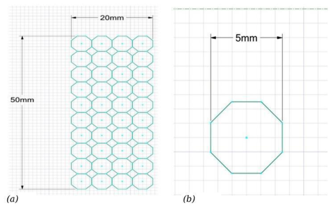
The multilayer wall system, fabricated from lightweight synthetic materials via additive manufacturing, consists of four functional compartments arranged successively from interior to exterior, as described in Section 2.1: (1) an aluminum-magnesium alloy structural layer of 5 mm thickness; (2) a boron nitride-doped ceramic plate of 1 mm thickness; (3) a sealed compartment housing up to 290 stacked graphene sheets; and (4) a sealed outer compartment of approximately 30 µm thickness, positioned at the ambient-facing front face and integrated with the additively manufactured supporting structure, filled with a nanocomposite based on iron sulfide (Fe3S4) powder mixed with titanium dioxide (TiO2) nanoparticlesIt should be noted that the mesh configuration adopted in this study was constrained by the node limit of the ANSYS Student license and the small-scale geometry of the proposed shield (octagonal cross-section with 5 mm diameter and 6 mm total thickness), which represents an extreme case in terms of element-to-geometry size ratio. For full-scale cryogenic tank applications, where shield dimensions would be orders of magnitude larger, the mesh density adopted here (0.5 mm element size) would generate prohibitively large node counts; however, the mesh convergence study presented demonstrates that an element size of 1.5 mm yields results within 2.29% of the reference solution, confirming that a coarser mesh is fully adequate for larger geometries. Accordingly, the present numerical methodology can be readily scaled to full tank configurations by adjusting the element size proportionally to the characteristic shield thickness, without loss of solution accuracy. The section used in the following numerical experiments is defined as a rectangular domain of 50 mm × 20 mm, with each octagonal tile having a nominal diameter of 5 mm, as illustrated in Figure 3.
The simulated domain consists of a two-body composite assembly comprising an AA5083 aluminium-magnesium alloy layer (5 mm thickness) and a boron nitride ceramic layer (1 mm thickness), forming a total shield thickness of 6 mm. The cross-sectional geometry follows an octagonal profile with a nominal diameter of 5 mm, as illustrated in Figure 2. The Graphene (1 µm) and Fe3S4–TiO2 (30 µm) layers were not represented as independently meshed volumetric domains because their characteristics thickness would require element sizes below the practical limit allowed by the available ANSYS Student licence. Instead, their influence was introduced through equivalent thermal resistance/contact conductance terms at the corresponding interfaces. This approach should be interpreted as an effective global representation of their contribution to the overall heat-leak response, rather than a fully resolved microscale simulation of radiation attenuation within the graphene stack or local flux damping inside the Fe3S4–TiO2 nanocomposite.
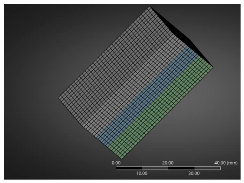
A mesh convergence study was conducted on the proposed composite shield model to ensure the independence of the numerical results from the spatial discretization. Two element sizes were evaluated: 0.5 mm (12,201 nodes) and 1.5 mm (1927 nodes). The total heat flux values obtained were 1720.8 W/m2 and 1681.4 W/m2, respectively, yielding a relative difference of 2.29%, which is within the accepted convergence threshold of 5% for steady-state thermal FEA. Accordingly, an element size of 0.5 mm was selected for the proposed shield as the reference mesh, while an element size of 1.5 mm was applied consistently to the patent-based comparative models (NASA US9617069B2: 50,675 nodes; JP2018-119634A: 45,575 nodes) [34,35] to ensure consistency across all analyses to ensure consistency across all analyses. The complete mesh parameters and corresponding heat flux results for the two models and for the two cases for the mesh of the proposed shield are presented in Table 4.
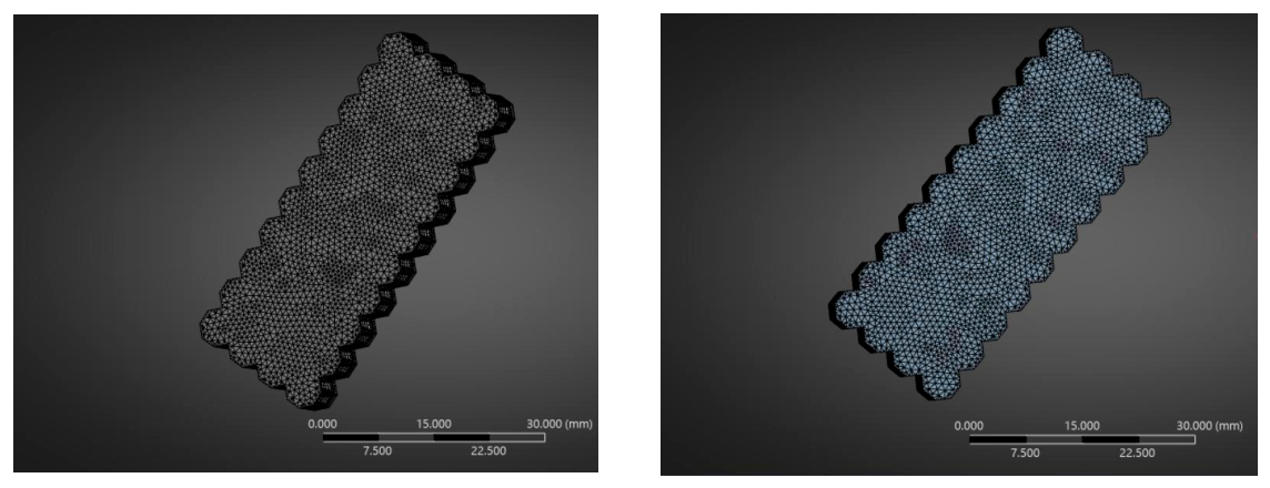
The finite element mesh was generated using an automatic tetrahedral meshing scheme with a global element size of 0.5 mm, which demonstrated solution independence within 2.29% relative to a 1.5 mm reference mesh. The resulting discretization provides adequate spatial resolution for accurate through-thickness thermal gradient capture across both constituent layers, as shown in Figure 4.
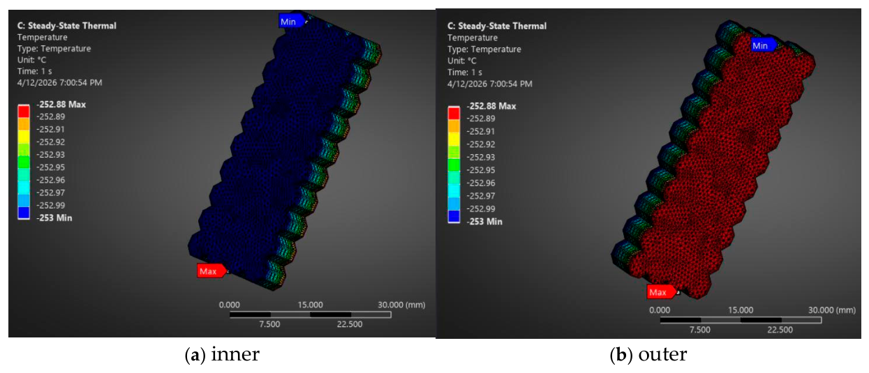
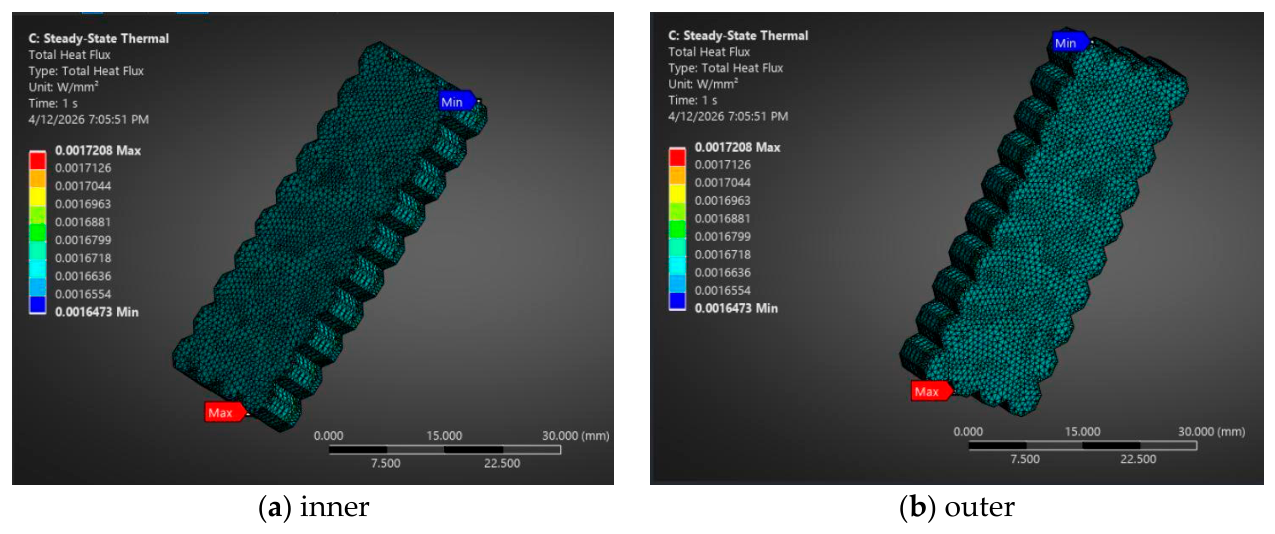
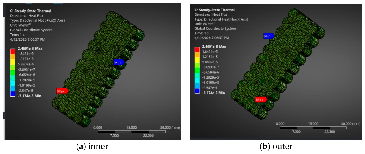
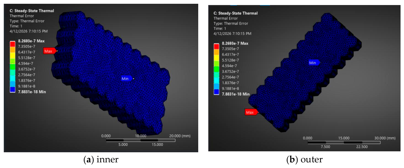
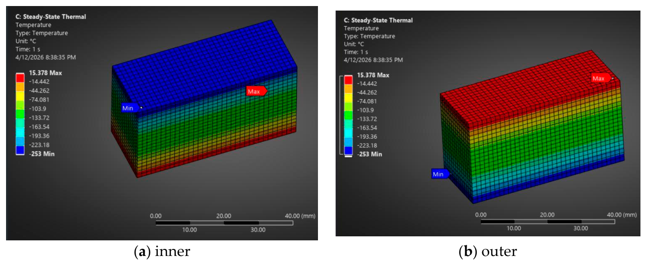
The thermal response of the multilayer shield under these boundary conditions is presented in Figure 5, Figure 6, Figure 7 and Figure 8. The steady-state thermal analysis of the proposed composite shield presented in Figure 5 yielded a temperature distribution ranging from −253 °C (20 K) at the inner surface to −252.88 °C at the outer surface, confirming the highly conductive nature of the constituent materials. The total heat flux shown in Figure 6 was found to be uniform across the shield cross-section, with values ranging from 1647.3 W/m2 to 1720.8 W/m2, yielding a mean value of q = 1684.1 W/m2. The near-uniform distribution (4.4% Max/Min variation) confirms the validity of the one-dimensional heat transfer assumption adopted in the analytical model. The directional heat flux along the lateral axis (X-direction) presented in Figure 7 ranged from −3.174 × 10⁻⁵ to 2.469 × 10⁻⁵ W/mm2, with the maximum values localized at the octagonal corner singularities of the mesh; across the bulk of the shield cross-section, the lateral heat flux was effectively negligible relative to the through-thickness component, confirming that heat transfer occurs predominantly in the normal direction and validating the one-dimensional conduction assumption adopted in the analytical model. The thermal error norm from the Figure 8 was below 8.27 × 10⁻⁷, confirming full numerical convergence of the solution. The total heat leak rate through the shield was calculated as Q ˙ = q A , and the corresponding LH2 boil-off rate was determined using Equation (13): m ˙ b o i l o f f = Q ˙ h f g , L H 2 , where h f g , L H 2 = 446 k J k g at normal boiling point (20.3 K, 1 atm).

3.2. Thermal Analysis—NASA US9617069

The NASA US9617069 insulation system was modelled as a five-layer planar assembly comprising, from inner to outer surface: two Cryogel aerogel blanket layers (5 mm each), two Reflectix double-bubble radiant barrier layers (8 mm each), and a vinyl wrap outer layer (1 mm), forming a total shield thickness of 27 mm [34]. The geometry was defined as a rectangular domain of 50 mm × 20 mm, consistent with the unit-cell modelling approach adopted throughout this study.
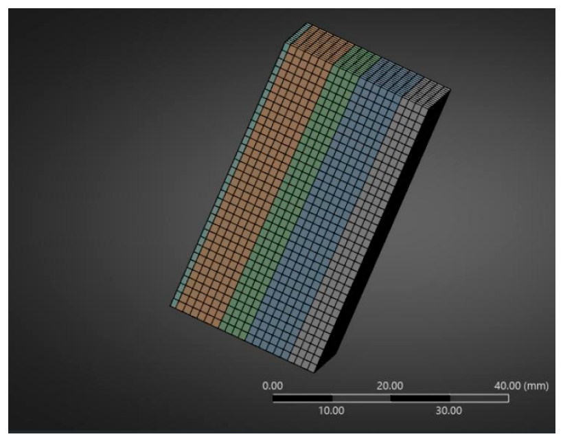
The finite element mesh was generated using a hexahedral dominant meshing scheme with a global element size of 1.5 mm, which demonstrated solution convergence within 2.29% for the reference composite shield geometry. The resulting discretization comprises 50,675 nodes, within the solver license limit, and provides adequate spatial resolution for accurate through-thickness thermal gradient capture across all five constituent layers, as shown in Figure 9. The bonded contact condition was applied at all four inter-layer interfaces. The two Cryogel aerogel layers are presented in grey and green colours, the two Reflectix radiant barrier layers are represented in blue and orange colours, and the one vinyl wrap layer is presented in blue-grey colour.
The thermal boundary conditions applied to the NASA US9617069 model were defined consistently with those adopted for the proposed composite shield [34]. A fixed temperature of 20 K (−253 °C) was imposed on the inner face of the innermost Cryogel aerogel layer, representing the direct contact surface with liquid hydrogen,. A combined convective-radiative boundary condition, was applied to the outer face of the vinyl wrap layer, comprising a natural convection coefficient of h = 5 W/m2·K with an ambient temperature of 300 K, consistent with natural convection of air in an enclosed facility environment, and a surface radiation condition with emissivity ε = 0.05 and a surrounding temperature of 300 K. The four lateral faces of the assembly were left unconstrained, defaulting to the adiabatic zero heat flux condition implicit in the ANSYS Steady-State Thermal solver, enforcing the one-dimensional heat transfer assumption adopted throughout this study.
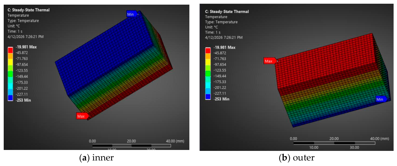
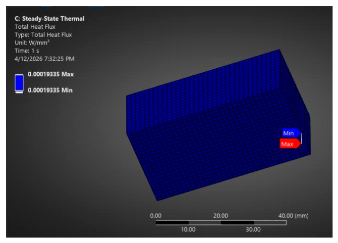
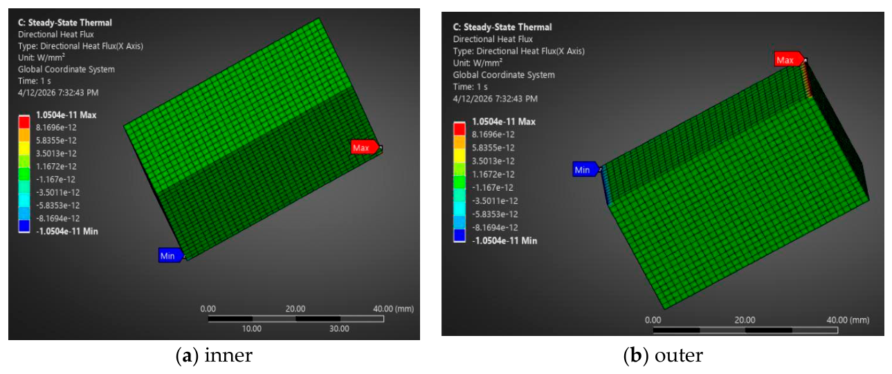
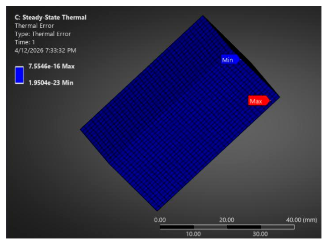
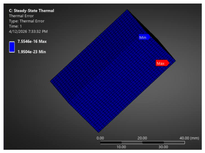
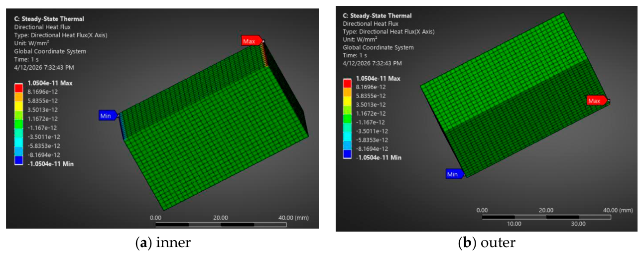
The steady-state thermal analysis of the NASA US9617069 insulation system yielded a temperature distribution ranging from −253 °C (20 K) at the inner surface to −19.981 °C (253.17 K) at the outer surface, demonstrating a temperature gradient of 233.17 °C across the 27 mm shield thickness, as shown in Figure 10. This significantly larger gradient compared to the proposed composite shield confirms the superior thermal insulation performance of the aerogel-based multilayer system. The total heat flux, presented in Figure 11, was perfectly uniform across the shield cross-section, with Max = Min = 193.35 W/m2, confirming ideal one-dimensional heat transfer behavior. The directional heat flux, shown in Figure 12, along the lateral axis was ±1.05 × 10⁻¹¹ W/mm2, effectively zero, further validating the one-dimensional assumption. The thermal error norm, presented in Figure 13, was below 7.55 × 10⁻¹⁶, confirming full numerical convergence.

3.3. Thermal Analysis—JP2018-119634A

The JP2018-119634A insulation system was modelled as a three-layer planar assembly comprising, from inner to outer surface: two vacuum insulation panel (VIP) layers (10 mm each) and a polyurethane foam (PUF) intermediate layer (8 mm), forming a total shield thickness of 28 mm, consistent with the configuration 20A described in the patent documentation. The geometry was defined as a rectangular domain of 50 mm × 20 mm, consistent with the unit-cell modelling approach adopted throughout this study. All three constituent layers were modelled as distinct volumetric bodies with individual material property assignments. The finite element mesh was generated using a hexahedral dominant meshing scheme with a global element size of 1.5 mm. The resulting discretization comprises 45,575 nodes, within the solver license limit, and provides adequate spatial resolution for accurate through-thickness thermal gradient capture across all three constituent layers, as shown in Figure 14. The two vacuum insulation panel layers are represented in grey and green colours, and the intermediate layer made from polyurethane foam is presented in blue colour.
The thermal boundary conditions applied to the JP2018-119634A model were defined consistently with those adopted for the proposed composite shield and the NASA US9617069 configuration. A fixed temperature of 20 K was imposed on the inner face of the interior vacuum insulation panel layer, representing the direct contact surface with liquid hydrogen,
A combined convective-radiative boundary condition, was applied to the outer face of the exterior vacuum insulation panel layer, comprising a natural convection coefficient of h = 5 W/m2·K with an ambient temperature of 300 K, consistent with natural convection of air in an enclosed facility environment, and a surface radiation condition with emissivity ε = 0.80 and a surrounding temperature of 300 K, consistent with the polymeric gas barrier film forming the outer surface of the vacuum insulation panel, as the outer envelope of commercial VIP units typically consists of multi-layer laminated polymer films with emissivity values in the range 0.75–0.85 [30].
The four lateral faces of the assembly were left unconstrained, defaulting to the adiabatic zero heat flux condition implicit in the ANSYS Steady-State Thermal solver, enforcing the one-dimensional heat transfer assumption adopted throughout this study. It is noted that the emissivity value adopted for the JP2018-119634A [35] outer surface ( ε = 0.80) differs from that of the NASA US9617069 system ( ε = 0.05) [34], reflecting the fundamental difference in outer surface material between the polymeric VIP envelope and the polished aluminium foil of the Reflectix radiant barrier layer.
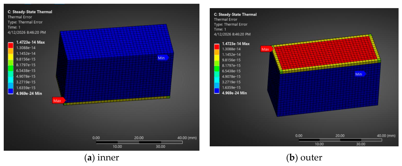
The steady-state thermal analysis of the JP2018-119634A insulation system yielded a temperature distribution ranging from −251 °C (22 K) at the inner surface to 15.378 °C (288.5 K) at the outer surface, demonstrating the largest temperature gradient of 266 °C across the 28 mm shield thickness among all three configurations analyzed, as shown in Figure 15. This result confirms the superior thermal insulation performance of the vacuum insulation panel-based system. The total heat flux was perfectly uniform, with Max = Min = 37.975 W/m2, representing the lowest heat flux value obtained in this study, as shown in Figure 16. The directional heat flux, presented in Figure 17, along the lateral axis was ±5.10 × 10⁻¹² W/mm2, effectively zero, confirming ideal one-dimensional heat transfer behavior. The thermal error norm, shown in Figure 18, was below 1.43 × 10⁻¹⁴, confirming full numerical convergence of the solution.

3.4. Thermo-Structural Analysis—Proposed Shield

The coupled thermo-structural analysis of the proposed composite shield was performed by importing the steady-state temperature distribution as a body load into the Static Structural solver, with a reference temperature of 300 K corresponding to the assembly condition. A fixed support boundary condition was applied to the inner face of the AA5083 layer. It is important to emphasise that this analysis accounts exclusively for the thermal loading arising from the temperature difference between the assembly reference condition (300 K) and the cryogenic operating temperature (20 K), and does not consider any other mechanical loads to which the insulation system may be exposed during service, such as internal pressure, inertial and vibration loads, acoustic loading, attachment stresses, or repeated cryogenic thermal cycling. The contribution of these additional load cases to the structural response of the shield is discussed qualitatively in Section 4.
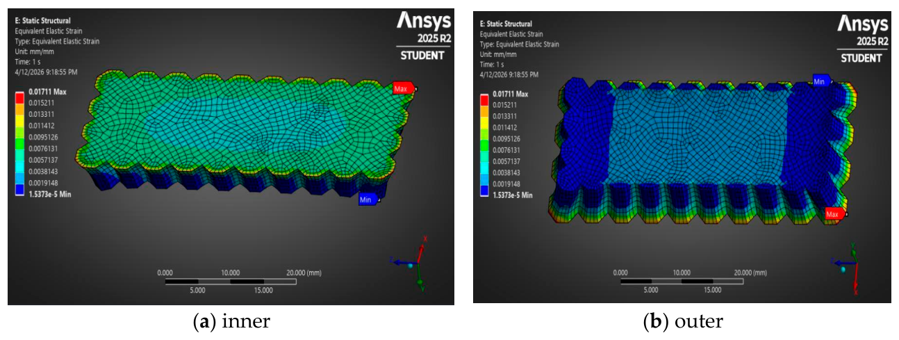
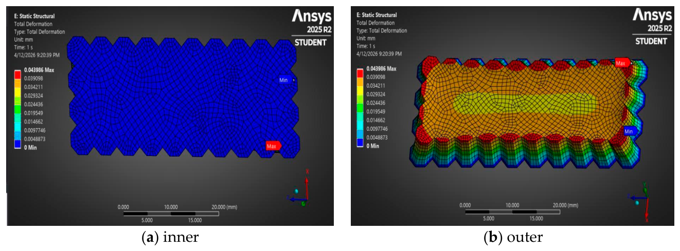
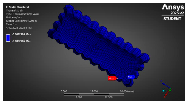
The equivalent elastic strain, presented in Figure 19, ranged from 1.54 × 10⁻⁵ to 0.01711, with the maximum values localized at the octagonal cross-section corners, consistent with the geometric stress concentration expected at sharp re-entrant features. The bulk strain values across the shield cross-section were significantly lower, confirming that the corner concentrations do not represent a global failure mode. The total deformation from Figure 20 ranged from 0 mm (fixed support face) to 0.0044 mm, indicating negligible thermally-induced displacement under steady-state cryogenic conditions. This result confirms the dimensional stability of the proposed shield at 20 K operating temperature. The thermal strain, shown in Figure 21, was uniform at −0.003299, corresponding to a thermal contraction of 0.33% from the reference temperature of 300 K to the operating temperature of 20 K.
The safety factor was calculated according to the maximum normal stress criterion as: S F = σ y i e l d σ m a x , where σ y i e l d is the tensile yield strength of the constituent material and σ m a x is the maximum principal stress obtained from the FEA solution [26,36].
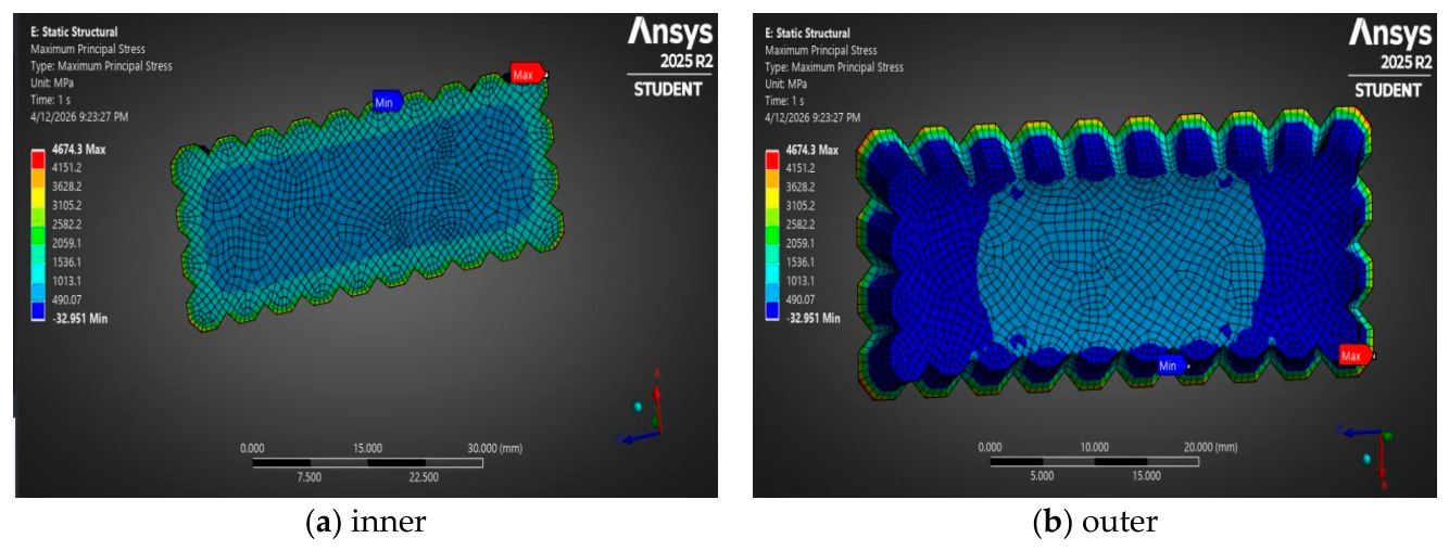
The maximum principal stress analysis yielded a peak tensile stress of 4674 Pa (0.0047 MPa), corresponding to safety factors of 64,182 relative to the tensile yield strength of AA5083 (300 MPa) and 17,114 relative to BN (80 MPa). The minimum principal stress of −32.951 Pa indicates negligible compressive loading, as shown in Figure 22. These results confirm that the proposed composite shield operates well within the elastic regime under cryogenic thermal loading, with no risk of tensile or compressive failure at 20 K operating conditions.

3.5. Comparative Analysis

Table 5 presents a comprehensive comparison of the thermal and structural performance of the three insulation configurations analyzed in this study. From a thermal perspective, the JP2018-119634A vacuum insulation panel system demonstrated the lowest heat flux of 37.975 W/m2, representing a reduction of 80.4% relative to the NASA US9617069 aerogel-based system (193.35 W/m2) and 97.8% relative to the proposed composite shield (1720.8 W/m2). The corresponding LH2 boil-off rates follow the same trend, with JP2018-119634A achieving the lowest value of 0.307 g/hour, compared to 1.560 g/hour for NASA US9617069 and 13.90 g/hour for the proposed composite shield.
The comparative analysis therefore reveals a fundamental trade-off between thermal insulation performance and structural suitability of the constituent materials. The JP2018-119634A system is optimal for applications where minimizing boil-off is the primary design objective, while the proposed AA5083/BN composite shield employs structurally robust materials (AA5083, BN) that remain within the elastic regime under the thermal contraction load case assessed here. It should be noted, however, that full structural load-bearing capability at cryogenic temperatures has not been demonstrated, as the present FEA considers only thermally induced loading; the response to internal pressure, inertial loads, vibration, and other service conditions remains to be evaluated in future work. The NASA US9617069 system represents an intermediate solution, offering improved thermal performance over the proposed shield while maintaining greater mechanical resilience than the VIP-based JP2018 configuration.
A further distinction between the proposed composite shield and the patent-based systems concerns the traceability and specificity of material property data. The proposed shield employs well-characterized engineering materials, AA5083 aluminium-magnesium alloy, hexagonal boron nitride, graphene, and Fe3S4-TiO2 composite—for which mechanical, thermal, and chemical properties are documented in peer-reviewed literature and international material databases [27]. This enables rigorous coupled thermo-structural FEA with validated input parameters.
In contrast, the patent-based systems employ proprietary or insufficiently characterized materials. The NASA US9617069 system specifies Cryogel and Reflectix by commercial trade name without defining the precise material composition, microstructure, or cryogenic-temperature property data required for structural analysis. Similarly, the JP2018-119634A system employs vacuum insulation panels whose core material composition and mechanical properties at 20 K are not disclosed in the patent documentation. The absence of standardized material property data for these systems precludes coupled thermo-structural FEA and limits the scope of numerical validation to thermal analysis only.

4. Discussions

The multilayer composite thermal shield proposed in this work is positioned against documented prior-art cryogenic insulation architectures, with the comparative analysis focused on the design attributes most critical to aerospace applications: vacuum independence, mechanical robustness under thermomechanical cycling, mass efficiency, geometric adaptability to curved tank surfaces, and manufacturing scalability.
The higher heat flux of the proposed shield (q = 1720.8 W/m2) relative to NASA US9617069 (q = 193.35 W/m2) and JP2018-119634A (q = 37.975 W/m2) is a direct and physically expected consequence of the difference in total thickness and constituent material thermal conductivity. The proposed shield spans only 6 mm, compared to 27 mm and 28 mm for the reference systems, while the AA5083 structural layer (k ≈ 121 W/m·K at 300 K) has thermal conductivity orders of magnitude higher than aerogel blankets (k ≈ 0.018 − 0.026 W/m·K) or vacuum insulation panels (k ≈ 0.002 W/m·K), resulting in a total thermal resistance approximately 8.9 times lower than NASA US9617069 and 45 times lower than JP2018-119634A. This trade-off is intentional: the AA5083 layer is dimensioned for structural integrity rather than maximum thermal resistance per unit thickness, representing a different point in the design space from insulation-only blanket or panel systems.
A layer-by-layer resistance analysis clarifies each compartment’s contribution. Using room-temperature properties as first-order estimates: RAA5083 = 4.1 × 10⁻⁵ m2K/W; R_BN = 3.0 × 10⁻⁵ m2K/W; Rgraphene + Rnano ≈ 7.5 × 10⁻⁶ m2K/W; and Rconv = 0.20 m2K/W. The convective boundary resistance dominates the series network, explaining why the temperature difference across the solid shield is only ~0.12 K while the bulk of the 280 K overall drop occurs across the air-side boundary layer [36,38]. Under forced convection conditions, the solid-layer resistance would become the governing term, with the BN plate, highest resistance-per-thickness ratio among the resolvable solid layers, playing the most significant role.
The thermo-structural results require contextual interpretation. The peak principal stress of 0.0047 MPa under pure thermal contraction (300 K to 20 K) yields safety factors of 64,182 relative to AA5083 yield strength and 17,114 relative to BN tensile strength, physically consistent with the constrained contraction of a thin, compact structure, the estimated free thermal contraction at ΔT = 280 K is approximately 0.039 mm, confirmed by the maximum total deformation of 0.0044 mm [26,36]. These safety factors apply exclusively to the thermal contraction load case and should be interpreted as upper-bound estimates; internal pressure, inertial loads, vibration, attachment stresses, and repeated cryogenic cycling are all expected to generate substantially higher stresses and must be addressed in future work. Additionally, all interfaces were treated as perfectly bonded, which may underestimate local thermal resistance and interfacial stress concentrations; explicit modelling of the partition wall interfaces between additively manufactured compartments, including inter-layer thermal contact resistance and cryogenic interface strength characterisation, should be addressed in future work.
A critical limitation concerns the assumption of ideal, fully dense material properties. Additive manufacturing processes produce residual porosity of 0.1–5% depending on parameters and post-processing, which reduces thermal conductivity approximately linearly with void fraction and degrades fatigue strength by 20–40% relative to fully dense reference values [14,15]. Furthermore, the graphene and Fe3S4-TiO2 layers are represented through equivalent thermal resistance/contact conductance rather than fully resolved volumetric meshing; the model therefore primarily captures the conductive and thermo-structural response of the AA5083/BN load-bearing assembly, and the present results should not be interpreted as an independent verification of the graphene radiative attenuation mechanism or the Fe3S4-TiO2 flux-damping mechanism [23,24,25]. Fully coupled radiation-conduction modelling or cryogenic experimental measurements will be required to verify these mechanisms directly, and experimental characterization of the as-printed material properties, including porosity mapping, cryogenic tensile testing, and thermal conductivity measurement at 20 K, is required before FEA predictions can be compared against physical specimen behavior.
Regarding the stated design attributes, a distinction must be drawn between those directly supported by the FEA results and those that remain design-intent claims. Vacuum independence is confirmed: the shield’s thermal performance is entirely determined by solid-state material properties, and the FEA boundary conditions involve no vacuum assumption [32,33]. Geometric adaptability of the octagonal cross-section is a design argument supported by the unit-cell modelling approach but not yet demonstrated on curved surfaces; conformal coverage analysis on representative tank geometries is identified as future work. Mass efficiency can be partially estimated, the areal mass of the structural layers is approximately 15.15 kg/m2, yielding a specific thermal resistance of ~0.011 m4K/(W·kg), but a full comparison against the patent-based systems is not possible without their layer density data. Mechanical robustness under thermomechanical cycling was not assessed; fatigue, crack initiation, and AA5083-BN interface delamination under repeated thermal cycling must be addressed experimentally.
The thermal insulation structures of JP 7631096 B2 and JP2022181507A share a fundamentally analogous three-layer configuration (closed-cell expanded elastomer, vacuum-backed metallic-deposit insulation material, and outer expanded resin), targeting liquid hydrogen and liquid nitrogen containment. While both achieve effective passive insulation under controlled conditions, their viability in aerospace environments is compromised by the difficulty of sustaining a uniform vacuum envelope under vibration and repeated thermal cycling, the sensitivity of the metallic deposit layer to mechanical damage, and the limited adaptability of planar configurations to compound-curved tank geometries [32,33]. The non-vacuum multilayer composite system of US 9617069 B2 represents the conceptually closest prior-art precedent, sharing the multi-mode heat transfer suppression philosophy of the present work, but relying on compression-maintained interlayer contact susceptible to degradation under bending, impact, and vibration loading [36]. The vacuum insulation panel assembly of JP2017075636A and the layered structure of JP2018-119634A both remain dependent on long-term vacuum envelope integrity and gas barrier continuity, both of which are vulnerable to mechanical and thermal fatigue in operational aerospace systems [37,38].
The proposed architecture addresses the three principal shared limitations of these prior-art systems, vacuum dependency, compression-maintenance reliance, and multi-component assembly complexity, through vacuum-free solid-state thermal resistance, integral additive manufacturing of all functional compartments into a single module, and a modular octagonal geometry enabling tessellated assembly with independent module replaceability. It should be noted, however, that this comparison remains structural and conceptual in nature, as the referenced patent documents do not provide quantitative thermal performance data under equivalent boundary conditions, and future experimental characterization, including cryogenic thermal cycling tests, boil-off rate measurements, and mechanical load testing, will be required for a fully quantitative performance assessment [34,35].

5. Conclusions

This study presented the design and numerical verification of a multilayer composite thermal shield for cryogenic liquid hydrogen tank applications, with comparative analysis against two patent-based insulation systems: the NASA US9617069 aerogel-based layered composite and the JP2018-119634A vacuum insulation panel configuration.
Among the three configurations analyzed, only the proposed composite shield was subjected to a thermo-structural finite element assessment, because the reference patent-based systems do not provide sufficient cryogenic mechanical property data for equivalent structural modelling. Under the specific steady-state thermal contraction case considered, the proposed shield remained within the elastic regime, showing low deformation and low thermally induced stress. However, this result should be interpreted as a preliminary thermo-structural assessment rather than a complete structural qualification for liquid hydrogen tank service. Future work should extend the structural validation to include internal pressure, tank curvature, attachment constraints, vibration, launch acceleration, acoustic loading, repeated cryogenic cycling, and fatigue in order to evaluate the full operational envelope of the shield in practical LH2 storage systems.
The graphene and Fe3S4-TiO2 functional layers were included in the numerical model through equivalent thermal resistance/contact conductance formulations rather than as fully resolved volumetric domains. This modelling strategy was adopted because of the very small characteristic thicknesses of these layers, approximately 1 µm for the graphene stack and 30 µm for the Fe3S4-TiO2 nanocomposite, together with the node-count limitations of the available ANSYS Student licence. Therefore, the present numerical results should be interpreted as a global thermo-structural validation of the proposed multilayer shield and as an evaluation of its effective heat-leak response, rather than as a direct microscale verification of the radiation attenuation mechanism of the graphene stack or the local flux-damping mechanism of the Fe3S4-TiO2 layer. In contrast, the NASA US9617069 system places a polymeric elastomer (EPDM foam) in contact with the cryogenic fluid, which presents long-term chemical compatibility concerns at 20 K. The JP2018-119634A system relies on polyurethane foam adjacent to the cryogenic environment, which is known to suffer progressive embrittlement and cracking under repeated thermal cycling at cryogenic temperatures.
The proposed shield geometry, fabricated as an octagonal cross-section structure, is compatible with additive manufacturing processes, enabling complex near-net-shape fabrication that cannot be achieved with the layered blanket systems of NASA US9617069 or the panel-based construction of JP2018-119634A [34,35].
Within this modelling framework, the proposed shield demonstrates structural stability under cryogenic thermal loading and provides a manufacturable multilayer architecture suitable for further investigation. However, direct validation of the radiative attenuation and nanocomposite flux-damping functions will require future work involving refined submodelling, fully coupled conduction-radiation simulations, or experimental cryogenic testing. Overall, the present study provides a preliminary numerical verification of the structural feasibility and effective thermal response of the proposed multilayer composite shield, while identifying the direct validation of the graphene-based radiative attenuation and Fe3S4-TiO2 flux-damping mechanisms as a necessary direction for future work.
The comparative thermal analysis showed that the patent-based insulation systems provide lower heat flux than the proposed shield under the investigated boundary conditions. However, the proposed architecture remains relevant as a manufacturable, vacuum-free, modular concept that integrates structural and functional compartments within an additively manufactured geometry. Its main contribution at this stage is therefore the architecture-level numerical assessment of a compact multilayer shield concept, rather than final experimental validation or complete structural qualification.
Future work should address the limitations identified in the present study along four primary directions. First, experimental fabrication of representative shield specimens via powder bed fusion additive manufacturing, followed by cryogenic thermal cycling tests and boil-off rate measurements, is required to validate the FEA predictions against physical specimen behavior and to characterize the production-dependent material properties, including porosity, thermal conductivity at 20 K, and cryogenic tensile strength, of the as-printed assembly. Second, the thermo-structural assessment should be extended beyond the thermal contraction load case to include internal pressure, inertial and vibration loads, acoustic loading, attachment constraints, and repeated cryogenic cycling, in order to evaluate the full operational envelope of the shield in practical LH2 storage systems. Third, explicit modelling of the partition wall interfaces between additively manufactured compartments—replacing the perfectly bonded interface assumption—should incorporate measured cryogenic inter-layer thermal contact resistance and interface strength data for the as-printed AA5083/BN interface, consistent with the integral manufacturing approach in which no adhesive is present. Fourth, fully coupled radiation-conduction simulations and refined submodelling of the graphene compartment and Fe3S4-TiO2 outer layer are required for direct numerical verification of the radiative attenuation and flux-damping mechanisms, which could not be resolved within the node-count constraints of the present model.

6. Patents

A national patent request was filed prior to the present work in relation to the new novel multilayer polymer composite thermal shield featuring an integrated architecture that combines structural, ceramic, graphene-based, and nanocomposite layers concept: Thermally insulating multi-layered architecture with nanomaterials for cryogenic tanks, fabricated through additive manufacturing, Alexa-Andreea Crisan, reference no. A/00036-OSIM: 02.02.2026.

Author Contributions

Conceptualization, A.-A.C.; methodology, A.-A.C. and M.M.; validation, A.-A.C. and M.M.; formal analysis, A.-A.C., M.M., A.B. and D.-E.C.; investigation, A.-A.C. and M.M.; resources, A.-A.C. and M.M.; data curation, A.-A.C., M.M., A.B. and D.-E.C.; writing—original draft preparation, A.-A.C.; writing—review and editing, A.-A.C.; visualization, A.-A.C.; supervision, A.-A.C.; project administration, A.-A.C.; funding acquisition, A.-A.C. All authors have read and agreed to the published version of the manuscript.

Funding

This research was funded by internal funds of COMOTI-Romanian Research & Development Institute for Gas Turbines. As this work was supported by institutional internal funding, no grant number is applicable.

Data Availability Statement

The original contributions presented in this study are included in the article. Further inquiries can be directed to the corresponding author.

Conflicts of Interest

The authors declare no conflicts of interest.

References

  1. Shao, Q.; Jin, D.; Lu, Y.; Yu, Y.; Luo, L.; Sun, X.; Guan, C.; Wang, J.-Q. Performance evolution analysis of solid oxide electrolysis cells operating at high current densities. Int. J. Hydrogen Energy 2024, 57, 709–716. [Google Scholar] [CrossRef] [Scilit]
  2. Mukwanje, C.A.; Faik, A.; Nachtane, M. Current progress, challenges, and future prospects in composite cryogenic hydrogen storage tanks. Polym. Compos. 2025, 46, S48–S70. [Google Scholar] [CrossRef] [Scilit]
  3. Li, K.; Chen, J.; Tian, X.; He, Y. Study on the Performance of Variable Density Multilayer Insulation in Liquid Hydrogen Temperature Region. Energies 2022, 15, 9267. [Google Scholar] [CrossRef] [Scilit]
  4. Ratnakar, R.R.; Sun, Z.; Balakotaiah, V. Effective thermal conductivity of insulation materials for cryogenic LH2 storage tanks: A review. Int. J. Hydrogen Energy 2023, 48, 7770–7793. [Google Scholar] [CrossRef] [Scilit]
  5. Ding, Y.; Shao, D.; Jin, S.; Yu, M.; Wang, Y.; Jiang, L. Numerical Study on Composite Multilayer Insulation Material for Liquid Hydrogen Storage. Coatings 2024, 14, 1417. [Google Scholar] [CrossRef] [Scilit]
  6. Yu, Y.; Xie, F.; Li, Y. Advanced thermal insulation strategies for liquid hydrogen storage tanks in Martian environments. Astrodynamics 2025, 9, 837–854. [Google Scholar] [CrossRef] [Scilit]
  7. Nataj, Z.E.; Xu, Y.; Wright, D.; Brown, J.O.; Garg, J.; Chen, X.; Kargar, F.; Balandin, A.A. Cryogenic characteristics of graphene composites—Evolution from thermal conductors to thermal insulators. Nat. Commun. 2023, 14, 3190. [Google Scholar] [CrossRef] [Scilit] [PubMed]
  8. Scalia, T.; Bonventre, L.; Terranova, M.L. From Protosolar Space to Space Exploration: The Role of Graphene in Space Technology and Economy. Nanomaterials 2023, 13, 680. [Google Scholar] [CrossRef] [Scilit] [PubMed]
  9. Toto, E.; Lambertini, L.; Laurenzi, S.; Santonicola, M.G. Recent Advances and Challenges in Polymer-Based Materials for Space Radiation Shielding. Polymers 2024, 16, 382. [Google Scholar] [CrossRef] [Scilit] [PubMed]
  10. Zhu, M.; Li, G.; Gong, W.; Yan, L.; Zhang, X. Calcium-Doped Boron Nitride Aerogel Enables Infrared Stealth at High Temperature Up to 1300 °C. Nano-Micro Lett. 2021, 14, 18. [Google Scholar] [CrossRef] [Scilit]
  11. Yao, C.; Leahu, G.; Holicky, M.; Liu, S.; Fenech-Salerno, B.; Lai, M.C.; Larciprete, M.C.; Ducati, C.; Divitini, G.; Voti, R.L.; et al. Thermally Conductive Hexagonal Boron Nitride/Polymer Composites for Efficient Heat Transport. Adv. Funct. Mater. 2024, 34, 2405235. [Google Scholar] [CrossRef] [Scilit]
  12. Singh, B.; Han, J.; Meziani, M.J.; Cao, L.; Yerra, S.; Collins, J.; Dumra, S.; Sun, Y.-P. Polymeric Nanocomposites of Boron Nitride Nanosheets for Enhanced Directional or Isotropic Thermal Transport Performance. Nanomaterials 2024, 14, 1259. [Google Scholar] [CrossRef] [Scilit] [PubMed]
  13. Olsson, R.; Cameron, C.; Moreau, F.; Marklund, E.; Merzkirch, M.; Pettersson, J. Design, Manufacture, and Cryogenic Testing of a Linerless Composite Tank for Liquid Hydrogen. Appl. Compos. Mater. 2024, 31, 1131–1154. [Google Scholar] [CrossRef] [Scilit]
  14. Georgantzinos, S.K.; Papadopoulou, E.; Kostopoulos, G.; Voulgaris, S.; Tseni, A.; Bakalis, P.; Gkara, M.; Mitropoulou, C.C.; Lagaros, N.D. A Comprehensive Review of Additive Manufacturing for Space Applications: Materials, Advances, Challenges, and Future Directions. Adv. Eng. Mater. 2025, 27, e202501082. [Google Scholar] [CrossRef] [Scilit]
  15. Vakharia, V.S.; Leonard, H.; Singh, M.; Halbig, M.C. Multi-Material Additive Manufacturing of High Temperature Polyetherimide (PEI)–Based Polymer Systems for Lightweight Aerospace Applications. Polymers 2023, 15, 561. [Google Scholar] [CrossRef] [Scilit]
  16. Popescu, T.; Matei, C.O.; Culita, D.C.; Maraloiu, V.-A.; Rostas, A.M.; Diamandescu, L.; Iacob, N.; Savopol, T.; Ilas, M.C.; Feder, M.; et al. Facile synthesis of low toxicity iron oxide/TiO2 nanocomposites with hyperthermic and photo-oxidation properties. Sci. Rep. 2022, 12, 6887. [Google Scholar] [CrossRef] [Scilit]
  17. Parsons, J.; Alotaibi, M. The Application of Transition Metal Sulfide Nanomaterials and Their Composite Nanomaterials in the Electrocatalytic Reduction of CO2: A Review. Appl. Sci. 2023, 13, 3023. [Google Scholar] [CrossRef] [Scilit]
  18. Saha, S.; Sullivan, R.W. A review on gas permeability of polymer matrix composites for cryogenic applications. J. Compos. Mater. 2024, 58, 827–847. [Google Scholar] [CrossRef] [Scilit]
  19. Thyssenkrupp Materials (UK) Ltd. Aluminium Alloy 5083-O H111 Material Data Sheet; Thyssenkrupp Materials (UK) Ltd.: Cradley Heath, UK, 2016; Available online: https://ucpcdn.thyssenkrupp.com/_legacy/UCPthyssenkruppBAMXUK/assets.files/material-data-sheets/aluminium/5083-o-h111.pdf (accessed on 18 March 2026).
  20. Aalco—Ferrous and Non-Ferrous Metals Stockist. Aluminium Alloys—Aluminium 5083 Properties, Fabrication and Applications. AZoM, 19 April 2005. Available online: https://www.azom.com/article.aspx?ArticleID=2804 (accessed on 18 March 2026).
  21. AZoM. Boron Nitride (BN)—Properties and Information on Boron Nitride. Available online: https://www.azom.com/properties.aspx?ArticleID=78 (accessed on 18 March 2026).
  22. Accuratus Corporation. Boron Nitride BO Grade Material Properties. Accuratus Corporation, Phillipsburg, NJ, USA. Available online: https://accuratus.com/pdf/BNBOprops.pdf (accessed on 18 March 2026).
  23. Ossila Ltd. Graphene Properties and Applications. Ossila Ltd., Sheffield, UK. Available online: https://www.ossila.com/pages/graphene-properties-and-applications (accessed on 18 March 2026).
  24. Akanksha, U.R.; Lahiri, I.; Suresh, K.S. Graphene Properties, Synthesis and Applications: A Review. JOM 2023, 75, 1102–1122. [Google Scholar]
  25. Kunarti, E.S.; Syoufian, A.; Budi, I.S.; Pradipta, A.R. Preparation and Properties of Fe3O4/SiO2/TiO2 Core-Shell Nanocomposite as Recoverable Photocatalyst. Asian J. Chem. 2016, 28, 1343–1346. [Google Scholar] [CrossRef] [Scilit]
  26. Barron, R.F. Cryogenic Heat Transfer; Taylor & Francis: Philadelphia, PA, USA, 1999. [Google Scholar]
  27. Marquardt, E.D.; Le, J.P.; Radebaugh, R. Cryogenic Material Properties Database. In Proceedings of the 11th International Cryocooler Conference, Keystone, CO, USA, 20–22 June 2000; pp. 681–687. [Google Scholar]
  28. Huang, L.; Wang, T.; Deng, Y.; Yi, Y. Mechanical Properties of AA5083 in Different Tempers at Low Temperatures. IOP Conf. Ser. Mater. Sci. Eng. 2017, 279, 012002. [Google Scholar] [CrossRef] [Scilit]
  29. Van Sciver, S.W. Helium Cryogenics, 2nd ed.; Springer: New York, NY, USA, 2012. [Google Scholar]
  30. Duthil, P. Material Properties at Low Temperature. In CAS—CERN Accelerator School: Course on Superconductivity for Accelerators; CERN: Geneva, Switzerland, 2014; pp. 77–95. Available online: https://cds.cern.ch/record/1973682 (accessed on 9 April 2026).
  31. Roldan, A.; Santos-Carballal, D.; de Leeuw, N.H. A comparative DFT study of the mechanical and electronic properties of greigite Fe3S4 and magnetite Fe3O4. J. Chem. Phys. 2013, 138, 204712. [Google Scholar] [CrossRef] [Scilit]
  32. Anderson, O.; Ottermann, C.; Kuschnereit, R.; Hess, P.; Bange, K. Density and Young’s modulus of thin TiO2 films. Fresenius J. Anal. Chem. 1997, 358, 315–318. [Google Scholar] [CrossRef] [Scilit]
  33. Fickett, F.R.; Stiegert, D.T. Properties of Selected Materials at Cryogenic Temperatures; NIST Special Publication 917; National Institute of Standards and Technology: Boulder, CO, USA, 1996.
  34. Fesmire, J.E. Thermal Insulation System for Non-Vacuum Applications Including a Multilayer Composite. Patent US9617069B2, 11 April 2017. Available online: https://patents.google.com/patent/US9617069B2/en?oq=US+9617069+B2+ (accessed on 6 April 2026).
  35. Kawamizu, T.; Yomo, K.; Ishida, T. Heat Insulation Structure of Liquefied Gas Storage Tank. Patent JP2018119634A, 2 August 2018. Available online: https://patents.google.com/patent/JP2018119634A/en?oq=JP2018119634A (accessed on 6 April 2026).
  36. Incropera, F.P.; DeWitt, D.P.; Bergman, T.L.; Lavine, A.S. Fundamentals of Heat and Mass Transfer, 7th ed.; John Wiley & Sons: Hoboken, NJ, USA, 2011. [Google Scholar]
  37. Siegel, R.; Howell, J.R. Thermal Radiation Heat Transfer, 4th ed.; Taylor & Francis: New York, NY, USA, 2002. [Google Scholar]
  38. Cengel, Y.A.; Ghajar, A.J. Heat and Mass Transfer: Fundamentals and Applications, 5th ed.; McGraw-Hill Education: New York, NY, USA, 2014. [Google Scholar]
  39. Ozisik, M.N. Heat Conduction, 2nd ed.; John Wiley & Sons: New York, NY, USA, 1993. [Google Scholar]
  40. Holman, J.P. Heat Transfer, 10th ed.; McGraw-Hill: New York, NY, USA, 2010. [Google Scholar]
  41. Bejan, A. Heat Transfer; John Wiley & Sons: New York, NY, USA, 1993. [Google Scholar]
  42. Churchill, S.W.; Chu, H.H.S. Correlating equations for laminar and turbulent free convection from a vertical plate. Int. J. Heat Mass Transf. 1975, 18, 1323–1329. [Google Scholar] [CrossRef] [Scilit]
  43. Modest, M.F. Radiative Heat Transfer, 3rd ed.; Academic Press: Oxford, UK, 2013. [Google Scholar]
  44. Flynn, T.M. Cryogenic Engineering, 2nd ed.; Marcel Dekker: New York, NY, USA, 2005. [Google Scholar]
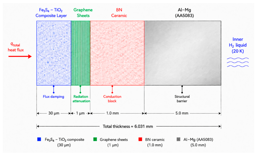
Figure 1. Schematic cross-section of the four-layer thermal shield architecture.
Aerospace 13 00475 g001
Figure 2. The layers of the proposed shield.
Aerospace 13 00475 g002
Figure 3. (a) The test design and dimensions of the thermal shield for cryogenic reservoir; (b) The diameter of a single octagonal tile.
Aerospace 13 00475 g003
Figure 4. Finite element mesh configuration with element size of 0.5 mm.
Aerospace 13 00475 g004
Figure 5. The temperature for Steady-State Thermal analysis—Proposed Shield (AA5083/BN/Graphene/Fe3S4-TiO2).
Aerospace 13 00475 g005
Figure 6. The total heat flux for Steady-State Thermal analysis—Proposed Shield (AA5083/BN/Graphene/Fe3S4-TiO2).
Aerospace 13 00475 g006
Figure 7. The directional heat flux for Steady-State Thermal analysis—Proposed Shield (AA5083/BN/Graphene/Fe3S4-TiO2).
Aerospace 13 00475 g007
Figure 8. The thermal error for Steady-State Thermal analysis—Proposed Shield (AA5083/BN/Graphene/Fe3S4-TiO2).
Aerospace 13 00475 g008
Figure 9. Finite element mesh configuration of the NASA US9617069 insulation system with element size of 1.5 mm.
Aerospace 13 00475 g009
Figure 10. The temperature for Steady-State Thermal analysis—NASA US9617069 configuration.
Aerospace 13 00475 g010
Figure 11. The Total Heat Flux for Steady-State Thermal analysis-NASA US9617069 configuration.
Aerospace 13 00475 g011
Figure 12. The Directional Heat Flux for Steady-State Thermal analysis—NASA US9617069 configuration.
Aerospace 13 00475 g012
Figure 13. The Thermal Error for Steady-State Thermal analysis-NASA US9617069 configuration.
Aerospace 13 00475 g013
Figure 14. Finite element mesh configuration of the JP2018-119634A insulation system with element size of 1.5 mm.
Aerospace 13 00475 g014
Figure 15. The Temperature for Steady-State Thermal analysis—JP2018-119634A configuration.
Aerospace 13 00475 g015
Figure 16. The Total Heat Flux for Steady-State Thermal analysis-JP2018-119634A configuration.
Aerospace 13 00475 g016
Figure 17. The Directional Heat Flux for Steady-State Thermal analysis—JP2018-119634A configuration.
Aerospace 13 00475 g017
Figure 18. The Thermal Error for Steady-State Thermal analysis—JP2018-119634A configuration.
Aerospace 13 00475 g018
Figure 19. The Equivalent Elastic Stress for Static Structural analysis.
Aerospace 13 00475 g019
Figure 20. The Total Deformation for Static Structural analysis.
Aerospace 13 00475 g020
Figure 21. The Thermal Strain for Static Structural analysis of the cryogenic shield.
Aerospace 13 00475 g021
Figure 22. The Maximum Principal Stress for Static Structural analysis.
Aerospace 13 00475 g022
Table 1. Material properties for aluminum-magnesium layer—AA5083, boron nitride, graphene and Fe3S4-TiO2 at room and cryogenic temperature.
MaterialTemperature ConditionDensity
( k g m 3 )
Young’s Modulus
GPa
Thermal Conductivity
( W m · K )
Poisson’s RatioTensile Ultimate Strength
MPa
Compressive Strength
MPa
Specific Heat
( J k g · K )
Melting Point
°C
AA5083room2650721210.3331771,000900570
AA5083cryogenic265080–8350–800.3344533010–20570
Boron nitrideroom190073.8330.278318616103400
Boron nitridecryogenic190078–825–150.2790–10200–2202–83400
Grapheneroom2250100050000.22130,0006000700-
Grapghenecryogenic22501020–1060200–8000.22135,000–140,0006000–70000.5–5-
Fe3S4-TiO2Room415012040.25130186650-
Fe3S4-TiO2cryogenic4150128–1331–20.25140–150200–2105–15-
Table 2. Material properties for two patent-based insulation systems.
MaterialOperating TemperatureDensity
( k g m 3 )
CompressibilityThermal Conductivity
( W m · K )
Compressive Strength
MPa
Vacuum Required
Comppressible Barrier Layer77 L to 373 K (extendable to 4 K)-Up to 75% full elastic recovery when load removed0.030–0.0350.180No (ambient pressure)
Aerogel Blanket77 L to 373 K (extendable to 4 K)-Flexible blanket (conformable)0.0178–0.0259-No (ambient pressure)
VIP (Vacuum Insulationa panel)Down to liquid gas temperatures-Rigid panel (no recovery)0.002-Yes—interior must be evacuated
PUf (Polyurethane Foam)Limited—degrades with gas substitution in closed cells-Rigid/brittle (no recovery)0.020-No
Table 3. Physical constants and reference values.
ConstantSymbolValue
Convection heat transfer coefficient h 5 W m 2 K
Stefan–Boltzmann constantσ5.67 × 10⁻⁸ W/m2·K4
Total emissivity of AA5083 ε 0.10
Radiative heat flux σ ε T s u r 4 9 1 0 4 W m 2
Latent heat of vaporization of liquid hydrogen at normal boiling point ( 20.3   K ,   1   a t m ) h f g , L H 2 446 k J k g
Table 4. Mesh convergence study results.
ModelElement Size (mm)Nodesq (W/m2)
Proposed shield0.512,2011720.8
Proposed shield1.519271681.4
NASA US96170691.550,675193.35
JP2018-119634A1.545,57537.975
Table 5. Comparative thermal performance of the analyzed insulation systems and limited thermo-structural response of the proposed shield under steady-state cryogenic thermal loading.
ParameterProposed Cryogenic ShieldNASA US9617069JP2018-119634A
Total thickness (mm)62728
q (W/m2)1720.8193.3537.975
R t o t a l (m2K/W) 0.163 1.448 7.374
m ˙ b o i l o f f (g/hour)13.91.5600.307
Ratio vs. JP201845.3 higher5.09 higherReference
Thermo-structural analysis performedYESNot assessed—insufficient mechanical data in patentNot assesed—insufficient mechanical data in patent
Max Principal Stress under Thermal Contraction only (MPa)0.0047N/AN/A
Safety Factor (AA5083)64,182N/AN/A
Disclaimer/Publisher’s Note: The statements, opinions and data contained in all publications are solely those of the individual author(s) and contributor(s) and not of MDPI and/or the editor(s). MDPI and/or the editor(s) disclaim responsibility for any injury to people or property resulting from any ideas, methods, instructions or products referred to in the content.