Article

Secure Uplink Transmission in UAV-Assisted Dual-Orbit SAGIN over Mixed RF-FSO Links

1
Center for Target Cognition Information Processing Science and Technology, Beijing Information Science and Technology University, Beijing 100192, China
2
Key Laboratory of Modern Measurement & Control Technology, Ministry of Education, Beijing Information Science and Technology University, Beijing 100192, China
3
School of Information and Communication Engineering, Beijing Information Science and Technology University, Beijing 100101, China
*
Author to whom correspondence should be addressed.
Aerospace 2026, 13(4), 341; https://doi.org/10.3390/aerospace13040341
Submission received: 9 March 2026 / Revised: 30 March 2026 / Accepted: 1 April 2026 / Published: 4 April 2026
(This article belongs to the Section Astronautics & Space Science)

Abstract

To meet the need for global coverage, space–air–ground integrated networks (SAGINs) are crucial, but the openness of wireless links makes communications vulnerable to eavesdropping. This paper investigates the physical layer security (PLS) of uplink transmissions in a cooperative dual-hop SAGIN. The system comprises a ground source with a directional antenna, an unmanned aerial vehicle (UAV) relay cluster, and a low Earth orbit (LEO) satellite. Utilizing stochastic geometry, we model the spatial randomness of terrestrial eavesdroppers and the multi-layered dual-orbital LEO destination. To combat mixed radio-frequency (RF) and free-space optical (FSO) fading, multiple relay selection and maximum ratio combining (MRC) are integrated into the UAV cluster. We analytically derive the piecewise probability density function for the FSO link distance, obtaining exact closed-form expressions for the end-to-end secrecy outage probability (SOP). Monte Carlo simulations strictly validate the derivations. The results demonstrate that while increasing available relays and antennas enhances PLS via spatial diversity, a security bottleneck restricts the RF-FSO architecture under high-transmit power regimes, generating asymptotic secrecy floors. These findings provide explicit theoretical guidelines for the secure design and parameter optimization of future SAGINs.

1. Introduction

To satisfy the stringent requirements of sixth-generation (6G) wireless networks, specifically concerning ubiquitous connectivity, high data transmission rates, and ultra-dense device integration, satellite communications have emerged as an indispensable paradigm [1,2,3,4,5]. Unlike traditional terrestrial infrastructures, satellite systems possess the inherent capability to provide extensive geographic coverage, effectively mitigating the connectivity divide in remote and underserved regions [6]. However, direct communication between ground terminals and high-altitude satellites is frequently bottlenecked by severe large-scale path loss, atmospheric impairments, and inevitable line-of-sight (LoS) blockages [7]. To fundamentally overcome these physical limitations, the space–air–ground integrated network (SAGIN) architecture, which integrates unmanned aerial vehicles (UAVs) as intermediate relays, has been recognized as a pivotal technological solution for establishing globally seamless 6G coverage [8]. Within this hierarchical framework, UAVs offer intrinsic advantages, including three-dimensional mobility, rapid deployment capabilities, and operational scalability. Furthermore, beyond serving as conventional relays, UAVs can function as dynamic airborne edge nodes. This multi-role capability extends reliable communication access to heavily shadowed terrestrial environments while significantly alleviating the stringent spectrum and power constraints imposed on orbital satellites [9].
Despite the extensive connectivity and deployment flexibility offered by the SAGIN architecture, the inherent broadcast nature of its cross-medium wireless links renders the transmitted data highly susceptible to unauthorized interception and eavesdropping [10] Conventionally, communication confidentiality is preserved through upper-layer cryptographic protocols. However, in the context of SAGINs, relying exclusively on network-layer encryption presents substantial limitations [11,12]. Traditional cryptographic algorithms necessitate excessive computational overhead, stringent key management and distribution protocols, and continuous energy consumption [13]. These rigid requirements are fundamentally incompatible with the severe resource constraints, limited processing capabilities, and strict power budgets typical of aerial relays and satellite nodes [10,14]. Furthermore, the potential emergence of advanced computational capabilities poses a persistent threat to the computational complexity assumptions underpinning contemporary cryptographic paradigms.
To address these critical vulnerabilities, increasing research has focused on alternative communication security frameworks for SAGINs [15]. Among these approaches, physical-layer security (PLS) has emerged as a highly promising and lightweight paradigm [16,17]. Rather than relying on computational intractability and secret keys, PLS directly exploits the intrinsic randomness and physical imperfections of the wireless propagation medium—such as channel fading, noise, and spatial diversity—to establish information-theoretic security [18]. By deliberately degrading the decoding capability at unauthorized receivers while maximizing the signal quality of the legitimate channel, PLS guarantees strict data confidentiality at the most fundamental transmission level, entirely independent of the eavesdroppers’ computational capacities [19,20].
Numerous studies have established fundamental analytical frameworks for the PLS of SAGINs. For instance, mathematical derivations of the SOP over composite fading channels were presented in [21]. Other investigations have predominantly isolated security analysis to either the terrestrial RF segment [22] or the FSO links [23], while some have incorporated emerging paradigms such as RIS [24,25]. Although the study in [26] provides a baseline for hybrid RF-FSO SAGINs, its analytical scope is fundamentally constrained by simplified spatial geometries—specifically, the assumption of a deterministic or single-layered satellite orbit. Consequently, existing models fail to capture the intricate stochastic interplay inherent in large-scale, heterogeneous spatial networks.
Specifically, current research has the following limitations: First, it rarely combines the spatial distribution of passive aerial eavesdroppers with the actual radiation direction of directional antennas from ground sources, a factor that mathematically alters the effective eavesdropping geometry. Second, the spatial randomness of the LEOs across multiple, distinct orbital shells remains unexplored. Furthermore, under these complex geometric conditions, the synergistic effects of advanced cooperative mechanisms on end-to-end PLS must be considered. Therefore, there is an urgent need for a comprehensive analytical model that can simultaneously consider the stochastic geometric characteristics of ground sources, air relays, and multi-layered LEOs nodes, and rigorously evaluate the precise end-to-end SOP on hybrid RF-FSO links to fill these critical research gaps.
To address the aforementioned research gaps, this paper establishes a comprehensive PLS analytical framework for a cooperative dual-hop SAGIN. The primary contributions are summarized as follows:
  • We propose a comprehensive framework for dual-orbit LEO satellites. This framework transforms the geometric relationship between satellites and relay stations into height constraints with geometric diversity, rather than a simplified fixed-distance point, thereby capturing the spatial randomness of multi-layer constellations.
  • Based on the random distribution of dual-orbit systems, the probability density function (PDF) of the link distance for FSO communication has been derived. This derivation provides a mathematical foundation for evaluating the performance of hybrid RF/FSO communication systems at different orbital altitudes.
  • By incorporating directional antennas at ground-based sources, we characterize the effective eavesdropping geometry for randomly distributed aerial nodes. This modeling accounts for spatial radiation patterns to provide a detailed assessment of the physical layer security for the aerial–terrestrial uplink.
The rest of this paper is organized as follows: Section 2 introduces the system descriptions, encompassing the network architecture, channel models, and signal formulations of the considered dual-hop SAGIN. Section 3 conducts a rigorous SOP analysis for the first-hop RF link, conditioned on the stochastic geometry of both the terrestrial eavesdroppers and the aerial relay cluster. Section 4 evaluates the outage probability (OP) of the second-hop FSO link under the multi-layered LEO dual-orbit architecture, and subsequently derives the exact end-to-end SOP for the entire system. Section 5 presents comprehensive numerical results and Monte Carlo simulations to validate our theoretical derivations. Finally, Section 6 concludes this paper.
The primary mathematical symbols and parameters used throughout this paper are summarized in Table 1.

2. System Descriptions

In this section, an in-depth exploration of the system model that forms the basis of this paper is presented. Firstly, the fundamentals of the space–air–ground integrated double-hop uplink relay network architecture and the corresponding channel fading models are introduced. Secondly, this is followed by an explanation of the eavesdropping scenario and the mathematical formulation of the received signals at each node.

2.1. System Model

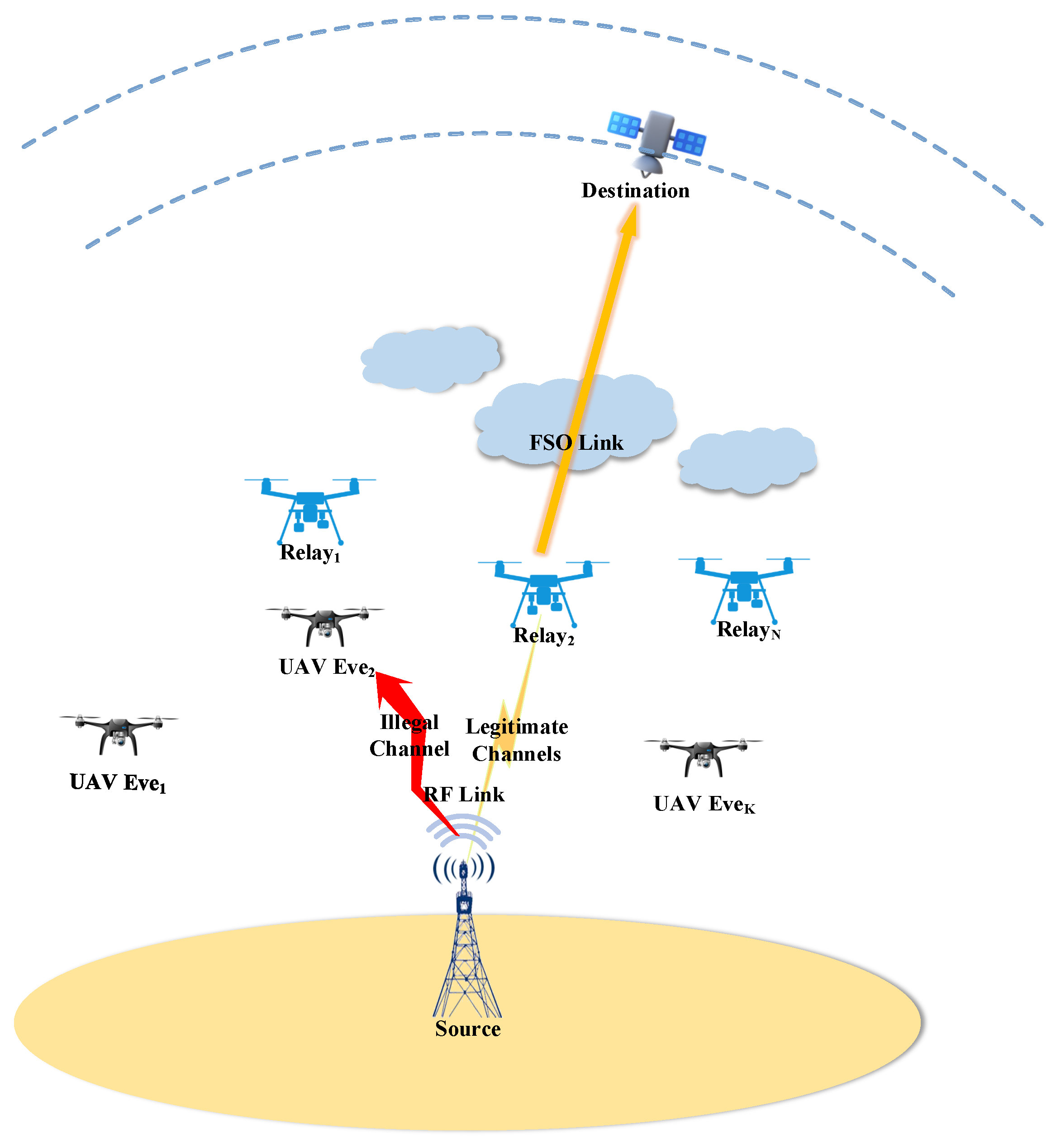
We consider a hybrid RF-FSO SAGIN, which consists of a terrestrial source (S), a cluster of aerial relays ( R i , 1 i N ), a satellite destination (D) operating under a dual-orbit FSO communication model, and a group of eavesdroppers (Eves) ( E k , 1 k K ), as shown in Figure 1. Specifically, the first-hop S- R i and S- E k links with RF transmission experience independent Nakagami-m fading [27], while the second-hop R i -D link with FSO transmission follows a unified Gamma–Gamma fading distribution incorporating the dual-orbit characteristics [28]. S transmits its confidential information to D via an optimal relay R * , which is chosen from the N available relays based on a specific multi-relay selection scheme, while the group of Eves attempt to overhear the confidential RF transmissions.
For simplicity, assume each relay node is equipped with at least two antennas ( L 2 ) and employs MRC to process received signals, thereby optimizing the instantaneous signal-to-noise ratio (SNR) [29]. Meanwhile, the source and each Eve are each configured with a single receiving antenna.
Furthermore, to facilitate statistical performance analysis, we assume that the UAV relays are deployed above the minimum altitude and are randomly distributed above that altitude. Additionally, as the high-altitude deployment of both UAVs and LEO satellites effectively mitigates terrestrial blockages, the R-D FSO link is modeled as a dominant line-of-sight LoS path. Finally, due to the inherent spatial secrecy of ultra-narrow laser beams, an eavesdropper must be precisely aligned within the propagation path; therefore, this paper neglects eavesdropping on the FSO link [24]. Although these assumptions provide a tractable analytical foundation, incorporating high-dynamic UAV mobility, non-line-of-sight FSO channels, and potential aerial FSO interception remains a promising direction for extending this research to more hostile environments.

2.2. Channel Model

2.2.1. S-R/E RF Link

The fading amplitudes of the RF links S R i and S E k , which describe the channel fading between the terrestrial source S and the i-th aerial relay ( 1 i N ), as well as between S and the k-th eavesdropper ( 1 k K ), are denoted by h q , where q { S R i , S E k } .
In our system, it is assumed that all these RF links experience independent Nakagami-m fading. Consequently, the channel power gain is denoted by γ q = | h q | 2 , with its PDF and cumulative density function (CDF) given by:
f γ q x = λ q m q Γ m q x m q 1 exp λ q x ,
If mq is an integer:
F γ q x = 1 exp λ q x k = 0 m q 1 λ q k x k k ! ,
and
F γ q = γ m q , λ q x Γ m q ,
here, λ q = m q / Ω q , wherein m q dictates the severity of the channel fading and Ω q represents the expected channel power gain. Furthermore, the mathematical operators Γ ( · ) and γ ( · , · ) designate the standard Euler Gamma function [30] (Equation (8.310.1)) and its lower incomplete counterpart [30] (Equation (8.350.1)), respectively.
Furthermore, assuming that a 1 × L single-input multiple-output (SIMO) architecture utilizing the MRC principle is adopted at the relay node R, the statistical properties of the equivalent channel under Nakagami-m fading can be determined. Specifically, the PDF and CDF of the combined channel power gain, denoted by γ S R , are respectively formulated as follows:
f γ S R x = λ R L m R Γ L m R x L m R 1 exp λ R x
F γ S R ( x ) = γ ( L m R , λ R x ) Γ ( L m R ) = 1 exp ( λ R x ) k = 0 L m R 1 ( λ R x ) k k ! ,
where λ R = m R Ω R .

2.2.2. R-D FSO Link

For the second hop, the optical transmission over the R D link is characterized by a Gamma–Gamma fading channel. This unified model is deliberately adopted as it comprehensively captures the joint impairments caused by pointing misalignments and the specific detection mechanisms employed. Accordingly, the analytical expressions for the PDF, denoted as f γ D ( x ) , and the CDF, F γ D ( x ) , of the instantaneous SNR γ D at the destination are formulated as follows:
f γ D ( x ) = A x 1 G 1 , 3 3 , 0 B x 1 r ξ 2 + 1 ξ 2 , a , b
F γ D ( x ) = I G r + 1 , 3 r + 1 3 r , 1 ρ x 1 , K 1 K 2 , 0
respectively, where A = ξ 2 r Γ ( a ) Γ ( b ) , B = h a b Ω D r , I = ξ 2 r a + b 2 ( 2 π ) r 1 Γ ( a ) Γ ( b ) , and ρ = ( h a b ) r Ω D r 2 r , with h = ξ 2 ξ 2 + 1 . Additionally, the parameter arrays are given by K 1 = Δ ( r , ξ 2 + 1 ) and K 2 = [ Δ ( r , ξ 2 ) , Δ ( r , a ) , Δ ( r , b ) ] , where the operator Δ ( k , a ) generates the sequence a k , a + 1 k , , a + k 1 k .
Here, a and b characterize the scintillation severity induced by atmospheric turbulence. The variable r denotes the detection mode used; specifically, r = 1 corresponds to heterodyne detection (HD), while r = 2 denotes intensity modulation with direct detection (IM/DD). In this work, the system is evaluated from a macroscopic statistical perspective under the assumption of relatively perfect alignment and synchronization. Specifically, to characterize the spatial stability of the laser beam, the pointing error coefficient ξ is mathematically defined as ξ = w e q / 2 σ j , which captures the statistical impact of the equivalent beam divergence ( Ψ R ) and spot jitter ( σ j ) [31]. Furthermore, while the high maneuverability of LEO satellites inevitably induces Doppler shifts and time-varying topological changes—which mathematically translate to dynamic, time-varying channel distribution functions—these effects are assumed to be effectively compensated by advanced carrier synchronization loops within our current static statistical framework [32]. The explicit characterization of time-varying FSO channel functions driven by real-time LEO motion and uncompensated Doppler effects is reserved for our future work. Finally, Ω D stands for the average electrical SNR of the optical link, and G p , q m , n [ · ] represents the classical Meijer’s G-function [30] (Equation (9.301)).

2.3. Signal Model

Since the system employs two distinct communication methods—RF and FSO—which typically utilize different modulation schemes, a decode-and-forward (DF) relay scheme is considered at R within the system [33].
In the first hop, during the initial transmission phase at time index t, the ground source S broadcasts the confidential symbol x s ( t ) to the relay network. This transmission signal is subject to a unit average power constraint, i.e., E [ | x s ( t ) | 2 ] = 1 . Therefore, the corresponding baseband signals observed by the ith relay node R i and the kth eavesdropper node E k can be expressed as follows:
y R i t = h SR i P S d R i η 1 x s t + n R ,
y E k t = h SE k P S d E k η 1 x s t + n E ,
wherein P S designates the transmission power emitted by the source node S. Furthermore, the additive white Gaussian noise (AWGN) components at R and E are modeled as circularly symmetric complex Gaussian variables, denoted by n R CN ( 0 , N R ) and n E CN ( 0 , N E ) , respectively. To account for large-scale signal attenuation, η 1 > 0 is defined as the path-loss exponent, while the physical spatial separations from S to R and from S to the k-th eavesdropper are represented by d R i and d E k , respectively.
Thus, the SNR at R i and E k can be written as follows:
γ R i = P S h SR i 2 N R d R i η 1 ,
γ E k = P S h SE k 2 N E d E k η 1 ,
respectively. The successful recovery of the transmitted symbol x s at the relay R is strictly contingent upon the instantaneous SNR γ R surpassing a strictly positive decoding threshold γ hold [34]. Failure to satisfy this threshold condition renders R unable to decode the information.
To minimize the detrimental effects of large-scale path-loss and bolster the legitimate transmission, a distance-based relay selection strategy is employed within the aerial network. Specifically, the optimal aerial relay, denoted as R * , is geometrically determined by identifying the node with the shortest spatial separation from the S. By defining this minimum distance as d R = min 1 i N { d R i } , the instantaneous SNR at the selected optimal relay R * is formulated as follows:
γ R = P S h SR * 2 N R d R η 1 ,
Similarly, we consider the worst-case eavesdropping scenario governed by symmetric small-scale fading conditions, where eavesdropping capability is also constrained by large-scale fading. Thus, the most threatening unauthorized receiver E * is the eavesdropper closest to the transmitter S. Let the shortest eavesdropping distance be d E = min 1 k K { d E k } . The equivalent signal-to-noise ratio intercepted by the strongest eavesdropper E * can be expressed as follows:
γ E = P S h SE * 2 N E d E η 1 ,
In the second hop, assuming the source message has been perfectly recovered, the selected relay node R * forwards the regenerated optical symbol x r to the destination D via a free-space optical communication link. Unlike overly simplified idealized models, the spatial instability of the laser beam—arising from pointing errors and beam jitter—is incorporated into our analytical framework via the pointing error coefficient ξ , as shown in (6) and (7). After propagating through the turbulent and misaligned channel, the incident optical beam is subsequently transformed into an electrical format via a photodetector. Hence, the equivalent electrical signal at D is formulated as follows:
y D t = ζ P R L FS L r I fso x r t + n D t ,
where P R specifies the allocated transmission power at the active relay, while ζ stands for the photodetector’s optical-to-electrical (O/E) conversion responsivity. The large-scale signal degradation is characterized by two distinct components. The first is the free-space path loss, defined as L F S = 4 π f c d D c 2 , wherein d D represents the propagation distance from the relay to D, c is the speed of light in a vacuum, and f c denotes the optical carrier frequency. The second component, L r (expressed in dB), aggregates miscellaneous system and atmospheric effects as L r = 1 2 ( G t + G r A A t m A l e n s e s A m a r ) [35]. Here, G t and G r are the respective transmitter and receiver gains, whereas A A t m , A l e n s e s , and A m a r correspond to the atmospheric attenuation, lens insertion losses, and the predefined system margin. Furthermore, the small-scale optical turbulence is captured by the fading coefficient I f s o , and n D ( t ) models the additive white Gaussian noise at the destination with zero mean and variance σ d 2 [36].
Therefore, the instantaneous received signal-to-noise ratio at D is:
γ D = P R ζ 2 L r 2 I fso 2 L FS σ d 2 Ω D I fso 2 ,
where
Ω D = P R ζ 2 L r 2 L FS σ d 2
indicates the average received signal-to-noise ratio at D.

3. Secrecy Performance Analysis of the First Hop

3.1. Preliminaries of the RF Links

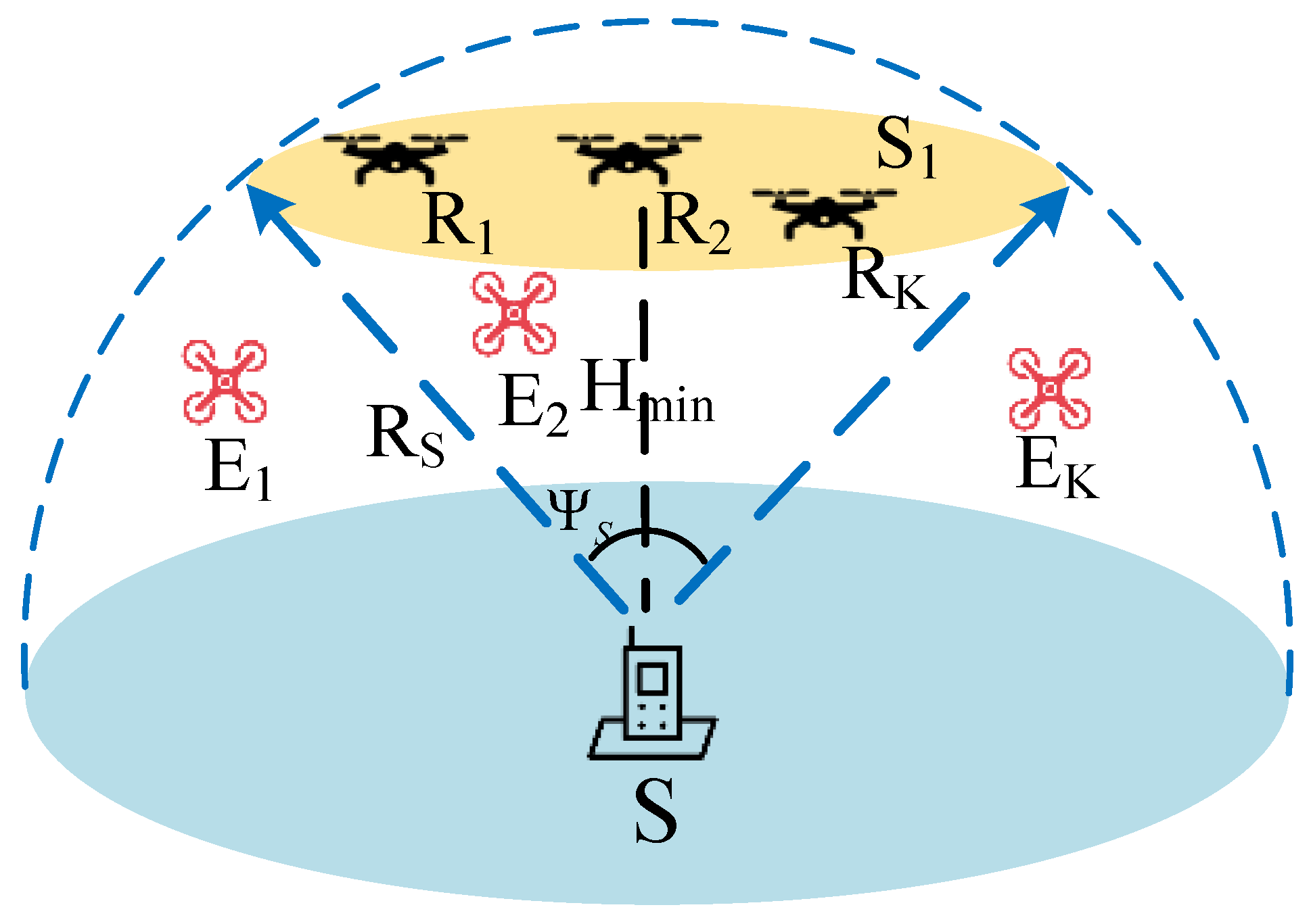
As visualized in Figure 2, the terrestrial source S is assumed to be equipped with an omnidirectional antenna, thereby projecting a hemispherical coverage area characterized by radius R S and centered at the origin O. Given the unpredictable nature of the wiretap nodes, the spatial topology is constructed by locating S at the origin and modeling the locations of all Eves as uniformly dispersed throughout this designated hemisphere. Consequently, the statistical distributions—specifically, the PDF and CDF—characterizing the random link distance between S and E k can be mathematically deduced as follows, respectively:
f d E k ( x ) = 3 x 2 R S 3 , if 0 x R S , 0 , otherwise .
F d E k ( x ) = 0 , if x < 0 , x 3 R S 3 , if 0 x R S , 1 , otherwise .
Therefore, the CDF and PDF of d E can be obtained as follows:
F d E d E = 1 1 d E 3 R S 3 K ,
Proof. 
See Appendix A. □
f d E d E = 𝜕 F d E d E 𝜕 d E = K 1 d E 3 R S 3 K 1 3 d E 2 R S 3 ,
respectively, where 0 d E R S .
Using the Jacobian determinant, the PDF of d E η 1 can be obtained as follows:
f d E η 1 x = f d E x 1 / η 1 𝜕 d E η 1 d E 1 = f = 1 K K f 3 f 1 f + 1 η 1 R S 3 f x 3 f η 1 1 ,
Taking practical flight restrictions into consideration, the active relay node R is assumed to hover at an elevation no lower than H min ( H min R S ) within the designated coverage zone of S. As visually depicted in Figure 2, this altitude threshold naturally limits the uniform spatial distribution of R exclusively to a spherical cap domain, S 1 . Based on spatial geometry, the parameters defining this cap include a base radius r cap = R S 2 H min 2 alongside a cap height h cap = R S H min . Based on these geometric bounds, the volume of the spherical cap S 1 is derived as follows:
V S 1 = π 3 2 R S 3 3 H min R S 2 + H min 3 .
To facilitate subsequent geometric analysis, the random spatial distribution of R is represented using spherical coordinates. Let ( r R , θ R , ψ R ) denote the instantaneous coordinates of the active relay. Thus, the CDF of the distance from S to R i can be expressed as follows:
F d R i ( x ) = 1 V S 1 0 arccos H min x H min cos θ x 0 2 π σ 2 sin θ d ψ d σ d θ = π 3 V S 1 2 x 3 3 H min x 2 + H min 3 .
So, the PDF of d R i is:
f d R i x = 2 π V S 1 x 2 H min x
Therefore, we obtain the PDF of d R as follows:
f d R ( x ) = 2 π N V S 1 x ( x H min ) 1 π 3 V S 1 ( x H min ) 2 ( 2 x + H min ) N 1
Proof. 
See Appendix B. □
Similarly, applying the Jacobian determinant transformation to Equation (25) yields the PDF of d R η 1 as follows:
f d R η 1 ( x ) = 2 π N η 1 V S 1 x 2 η 1 1 x 1 η 1 H min 1 π 3 V S 1 x 1 η 1 H min 2 2 x 1 η 1 + H min N 1 = k = 0 N 1 m = 0 2 k + 1 n = 0 k Φ k , m , n · x 3 k m n + 3 η 1 1
where H min η 1 x R S η 1 and
Φ k , m , n = 2 π N η 1 V S 1 π 3 V S 1 k 2 k n H min m + n ( 1 ) k + m N 1 k 2 k + 1 m k n
Therefore, letting Z = d R η 1 d E η 1 , we obtain the PDF of Z as follows:
f Z ( z ) = k = 0 N 1 m = 0 2 k + 1 n = 0 k j = 0 K 1 C k , m , n , j d max Λ · z α 1 d min Λ · z β j 1 , if H min η 1 R S η 1 z 1 , k = 0 N 1 m = 0 2 k + 1 n = 0 k j = 0 K 1 C k , m , n , j d max Λ d min Λ · z β j 1 , if z > 1 .
where d max = R S η 1 , d min = H min η 1 , Ψ j = 3 N η 1 [ 1 ( 1 p ) N ] N 1 j ( 1 ) j p R S 3 j + 1 , α = 3 k m n + 3 η 1 , β j = 3 ( j + 1 ) η 1 , Λ = α + β j = 3 ( k + j + 2 ) m n η 1 , C k , m , n , j = Φ k , m , n Ψ j Λ
Proof. 
See Appendix C. □

3.2. SOP Analysis for First Hop

Driven by the spatial randomness of the wiretap network, the occurrence of an eavesdropper-free coverage area constitutes a valid probabilistic event. This geometric uncertainty dictates that the security analysis of the S R transmission cannot be generalized by a single analytical metric. Instead, a conditional analytical framework is required. In scenarios where eavesdropping threats actively exist within the communication range, the SOP is derived to assess the security bottleneck. Conversely, in the strict absence of any unauthorized interceptors, the secure communication mathematically simplifies to standard reliable forwarding, prompting the evaluation to naturally transition to the traditional OP.
Considering the aforementioned scenarios, the overall confidentiality of the initial transmission is fundamentally determined by two mutually exclusive operational states resulting from the eavesdropper’s spatial randomness, specifically: (1) an environment assessed by the OP as free from eavesdroppers; and (2) a vulnerable environment constrained by the SOP conditions. Therefore, the comprehensive probability of confidentiality compromise must account for both metrics simultaneously. Thus the SOP 1 is defined as follows:
SOP 1 = P 0 · OP 1 + P 1 · SOP 1 L ,
where P 0 = ( 1 p ) N and P 1 = 1 P 0 denote the probabilities of the absence and presence of effective eavesdroppers within the coverage area, respectively.

3.2.1. SOP Analysis

Conditioned on the successful decoding of the information signal x s at R, the instantaneous secrecy capacity associated with the S R transmission can be expressed as follows:
C S ( γ R , γ E ) = max log 2 1 + γ R log 2 1 + γ E , 0 .
Following conventional physical layer security frameworks, the eavesdroppers are presumed to operate in a passive mode. This stealth strategy ensures maximum information interception without risking exposure. As a direct consequence of this passivity, the instantaneous CSI of the eavesdropping links is unavailable at the transmitter S. To quantify the security performance under this lack of CSI, the SOP is utilized as the primary metric. Specifically, conditioned on the successful decoding of the signal at R, the first-hop SOP represents the likelihood that the achievable secrecy capacity drops below a predefined threshold C th [37], which is formulated by:
SOP 1 L = P log 2 1 + γ R * 1 + γ E * < C th , γ R * γ th = P log 2 ( 1 + γ R * ) log 2 ( 1 + γ E * ) C th = P γ R * λ γ E * + λ 1 P γ R * λ γ E * ,
where λ = 2 C th . This indicates that γ hold < λ γ E , and the prerequisite for successful decoding at rate R is naturally incorporated into the criteria for positive confidentiality.
Therefore, in the air–ground–space system under consideration, the probability of a security breach in the first-hop communication link can be derived as follows:
SOP 1 L = 1 l = 0 L m R 1 l + m E 1 l k = 0 N 1 m = 0 2 k + 1 n = 0 k j = 0 N 1 C k , m , n , j T 1 + T 2 ,
where a 0 = λ λ R N R N E ,
T 1 = a 0 λ E l d m a x Λ · Δ F A d m i n Λ · Δ F B ,
T 2 = λ E a 0 m E d m a x Λ d m i n Λ β j + m E F 1 2 l + m E , β j + m E ; β j + m E + 1 ; λ E a 0 ,
F ( x , μ ) = x μ μ F 1 2 l + m E , μ ; μ + 1 ; a 0 λ E x
Δ F A = F ( 1 , l + α ) F ( ρ Z , l + α ) , Δ F B = F ( 1 , l β j ) F ( ρ Z , l β j ) , ρ Z = ( H min / R S ) η 1 , respectively, in which F 1 2 ( · , · ; · ; · ) denotes the hypergeometric function.
Proof. 
See Appendix D. □
The exact closed-form expression in (32) involves the Gauss hypergeometric function, F 1 2 ( · ) . Mathematically, this special function originates from the integration of the fading power envelope over the piecewise distance distribution. Specifically, the integration over the path-loss variable can be mapped to the standard integral identity [30] (Equation (3.194.1)):
0 u x μ 1 ( 1 + β x ) ν d x = u μ μ F 1 2 ( ν , μ ; 1 + μ ; β u ) .

3.2.2. OP Analysis

As governed by the stochastic spatial distribution of the unauthorized nodes, a specific geometric scenario arises where no eavesdroppers are present within the effective hemispherical coverage of the terrestrial source S. In such an eavesdropper-free environment, the wiretap link is virtually non-existent, implying that the capacity of the eavesdropping channel drops to zero. Consequently, the achievable secrecy capacity is entirely dictated by the transmission quality of the legitimate S R link. To evaluate the system’s reliability under this secure condition, the performance metric naturally transitions from the SOP to the conventional OP. Specifically, the OP for the first hop is defined as the probability that the instantaneous channel capacity of the selected optimal relay R * falls below the predefined target data rate C th , which can be expressed as follows:
OP 1 = Pr { γ R < γ out 1 } ,
where γ out 1 is the threshold for R to successfully decode the signal.
Therefore, in the absence of eavesdroppers, the OP 1 of the first jump link can be derived as follows:
OP 1 = 1 k = 0 N 1 m = 0 2 k + 1 n = 0 k W k , m , n Θ k , m , n ,
where μ = λ R γ o u t N R P S , τ = 3 k m n + 3 η 1 , W k , m , n = Φ k , m , n · μ τ , Θ k , m , n = q = 0 m R 1 1 q ! [ γ ( q + τ , μ R S η 1 )
γ ( q + τ , μ H min η 1 ) ] .
Proof. 
See Appendix E. □
Substituting (32) and (38) into (29) yields the SOP expression for the first-hop link.

4. Outage Performance for Second Hop

4.1. Preliminaries of the FSO Link

Given the deployment of FSO communication for the R D link, the inherent high directivity and ultra-narrow beamwidth of the laser signals fundamentally preclude the possibility of interception by unauthorized nodes. Consequently, the second-hop transmission is assumed to be intrinsically secure. Under this premise, the analytical focus of this section shifts exclusively toward the reliability of the legitimate link. Specifically, we thoroughly investigate how the stochastic positional distribution of the target satellite degrades the outage performance of the R D optical transmission.
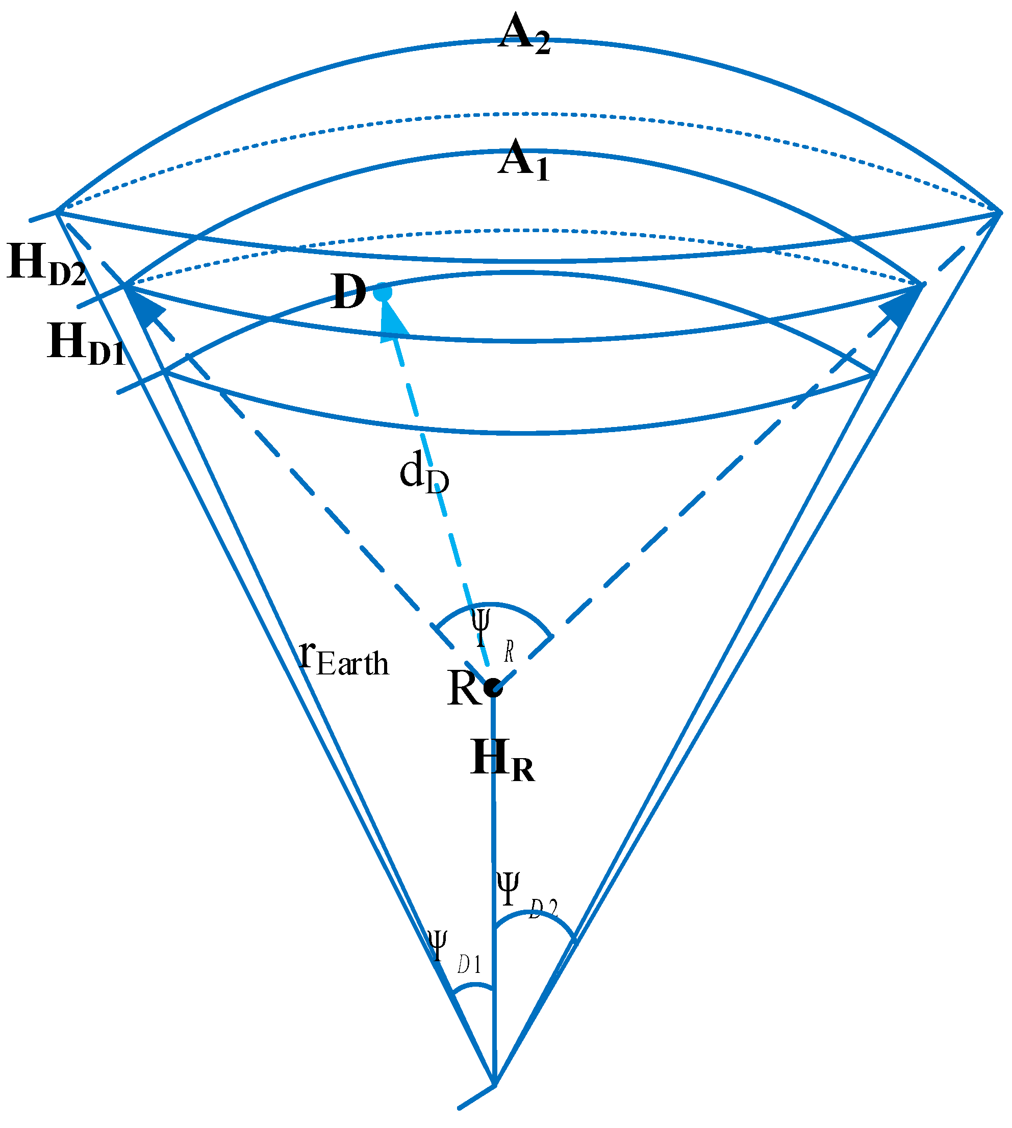
As depicted in Figure 3, the destination satellite D is postulated to follow a uniform spatial distribution across a dual-orbit architecture. Consequently, the orbital radius for a given shell i { 1 , 2 } is mathematically defined as r D , i = R earth + H D , i , where R earth denotes the Earth’s radius and H D , i signifies the specific altitude of the i-th orbit. Aided by advanced acquisition and tracking mechanisms [38], relay R is capable of achieving real-time spatial localization of D, thereby fulfilling the stringent alignment requirements of the highly directional FSO link. For analytical tractability in the subsequent derivations, a geocentric spherical coordinate system is adopted, anchoring the origin strictly at the center of the Earth. The relationship between the angle Ψ D at the center of the Earth and the beam angle Ψ R at point R is given by:
Ψ R i 2 tan 1 R earth + H D H D sin Ψ D i .
based on the established geocentric reference frame, the instantaneous location of the target satellite D in the i-th orbit is parameterized by the spherical coordinates ( r D , i , θ D , ψ D ) . Governed by the effective beam divergence and the receiver’s field of view, the angular dimensions are bounded by 0 θ D Θ max and 0 ψ D 2 π . To simplify the spatial geometry without loss of generality, the reference polar axis is perfectly aligned with the relay node R, yielding its simplified coordinates as ( H R , 0 , 0 ) . Here, the geocentric distance of the relay is given by H R = R earth + h R , where h R denotes its physical hovering altitude. Subject to the aerial deployment constraints defined in the first phase, the valid domain for H R is strictly limited to R earth + H min H R R earth + R S .
Therefore, the distance d D between R and D can be expressed as follows:
d D i = r D i 2 + H R 2 2 r D i H R cos θ D ,
based on the established spatial topology, the random transmission distance d D fluctuates within a deterministic interval, satisfying d D , min d D d D , max , where the lower and upper bounds are given by d D , min = r D H R and d D , max = r D 2 + H R 2 2 r D H R cos Ψ D , respectively. To facilitate the derivation of closed-form expressions for the ensuing performance analysis, the path-loss factor for this specific FSO transmission is uniformly assumed to be 2, which effectively aligns with standard free-space optical characteristics.
Assuming a uniform spatial distribution for D within the designated topology alongside a fixed altitude for R, the PDF of the squared distance d D 2 is given by:
f d D 2 ( w ) = r D 1 K , w range w 1 r D 2 K , w range w 2 r D 1 + r D 2 K , w range w 1 range w 2 0 , otherwise
where K = 2 H R r D 1 2 ( 1 cos Ψ D 1 ) + r D 2 2 ( 1 cos Ψ D 2 ) , w 1 , min = ( r D 1 H R ) 2 , w 1 , max = r D 1 2 + H R 2 2 r D 1 H R cos Ψ D 1 , w 2 , min = ( r D 2 H R ) 2 , w 2 , max = r D 2 2 + H R 2 2 r D 2 H R cos Ψ D 2 , range w 1 = ( w 1 , min , w 1 , max ) , range w 2 = ( w 2 , min , w 2 , max )
Proof. 
See Appendix F. □

4.2. OP Analysis for Second Hop

To evaluate the reliability of the second hop, the OP of the R D link is evaluated as the probability of the critical event wherein the instantaneous received SNR degrades below the predefined target threshold γ out 2 for error-free signal recovery.
OP 2 = Pr γ D < γ out 2 ,
where γ out 2 is the threshold for correct decoding at D.
Regarding the R D transmission phase, given that target node D exhibits uniform spatial distribution within the dual-track architecture, the precise expression for the interruption probability OP 2 yields:
OP 2 = I r D 1 ϵ K G int ( w 2 min , w 1 min ) + I ( r D 1 + r D 2 ) ϵ K G int ( w 1 max , w 2 min ) + I r D 2 ϵ K G int ( w 2 max , w 1 max ) ,
where
ϵ = 4 π f c σ d 2 h a b r P R c 2 ζ 2 L r 2 r 2 r γ out 2 ,
G int ( m , n ) = G r + 2 , 3 r + 2 3 r , 2 ϵ m | 1 , 2 , K 1 + 1 K 2 + 1 , 0 , 1 G r + 2 , 3 r + 2 3 r , 2 ϵ n | 1 , 2 , K 1 + 1 K 2 + 1 , 0 , 1 .
Proof. 
See Appendix G. □

4.3. End-to-End SOP Analysis

Having systematically characterized the transmission dynamics of both individual hops, we now evaluate the overall secrecy performance of the proposed dual-hop DF relaying system. In such an architecture, a strictly secure and reliable end-to-end communication session is accomplished if and only if the confidential message survives both consecutive transmission phases. Specifically, the information must successfully bypass the terrestrial eavesdropping threats in the first phase and subsequently overcome the severe atmospheric impairments over the FSO link in the second phase. Assuming that the fading channels of the RF and FSO links are statistically independent, the overall probability of a successful secure transmission is formulated as the product of the individual success probabilities. Consequently, the exact end-to-end SOP of the entire system is evaluated as follows:
SOP = 1 ( 1 SOP 1 ) ( 1 OP 2 ) .
where ( 1 SOP 1 ) denotes the probability of successful transmission for the first-stage RF link, and ( 1 OP 2 ) denotes the probability of successful transmission for the second-stage FSO link.
Substituting Equations (29) and (43) into (46) yields the final expression for the end-to-end SOP.

5. Numerical Results and Discussion

This section presents a comprehensive numerical evaluation intended to characterize the system’s security capabilities and to verify the mathematical validity of the established theoretical framework. To accurately replicate the dynamic physical environment—including the unpredictable channel gains over heterogeneous links and the geometric uncertainties associated with the aerial node and malicious interceptors—the simulation environment executes 10 6 independent Monte Carlo trials. For clarity and reproducibility, the baseline configuration utilized throughout the evaluations is outlined in Table 2.
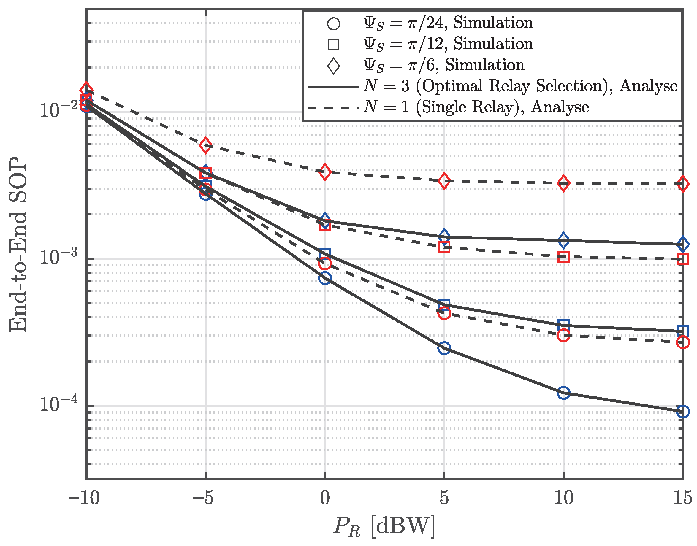
Figure 4 plots the end-to-end SOP versus P R for different Ψ S , comparing the optimal relay selection with a single-relay baseline. The match between analytical curves and Monte Carlo simulations validates the derivations. The results present three trends: SOP decreases as P R increases until reaching a security floor; narrower beamwidths improve security; and optimal relay selection outperforms the single-relay scheme. Here, the security floor is precisely defined as the asymptotic lower bound of the end-to-end SOP when P R . These phenomena highlight a bottleneck in the DF architecture. For large P R , the FSO link interruption probability approaches zero, leaving the RF link vulnerability to dominate the SOP. To mitigate this, reducing Ψ S restricts the signal scattering footprint and the probability of eavesdropping. Furthermore, optimal relay selection provides spatial diversity to bypass intercepted channels, achieving a lower security floor than the single-relay architecture.
These geometric and power-related observations provide both academic and practical insights for SAGINs. From a research perspective, although the proposed optimal relay selection lowers the confidentiality floor compared to the single-relay, the inevitable emergence of this floor indicates that enhancing the reliability of legitimate links through spatial diversity alone cannot guarantee strict end-to-end security. Future research will shift toward active physical-layer defense mechanisms targeting the RF vulnerability phase, such as artificial noise injection. Practically, the absence of extremes in these monotonically decreasing curves mathematically confirms that increasing P R never degrades security. However, these findings offer relevant guidance for system parameter selection: since continuous power scaling yields diminishing security benefits, the optimal transmit power should be selected at the knee point of the curve to balance safety and energy efficiency. Furthermore, the numerical results highlight that synergistically combining optimal relay selection with highly directional antennas becomes a cost-effective algorithmic and hardware strategy. This joint approach leverages spatial degrees of freedom to bypass intercepted channels while physically restricting the interception zone, comprehensively lowering the asymptotic floor and safeguarding air–ground interfaces against ground-based illegal interception.
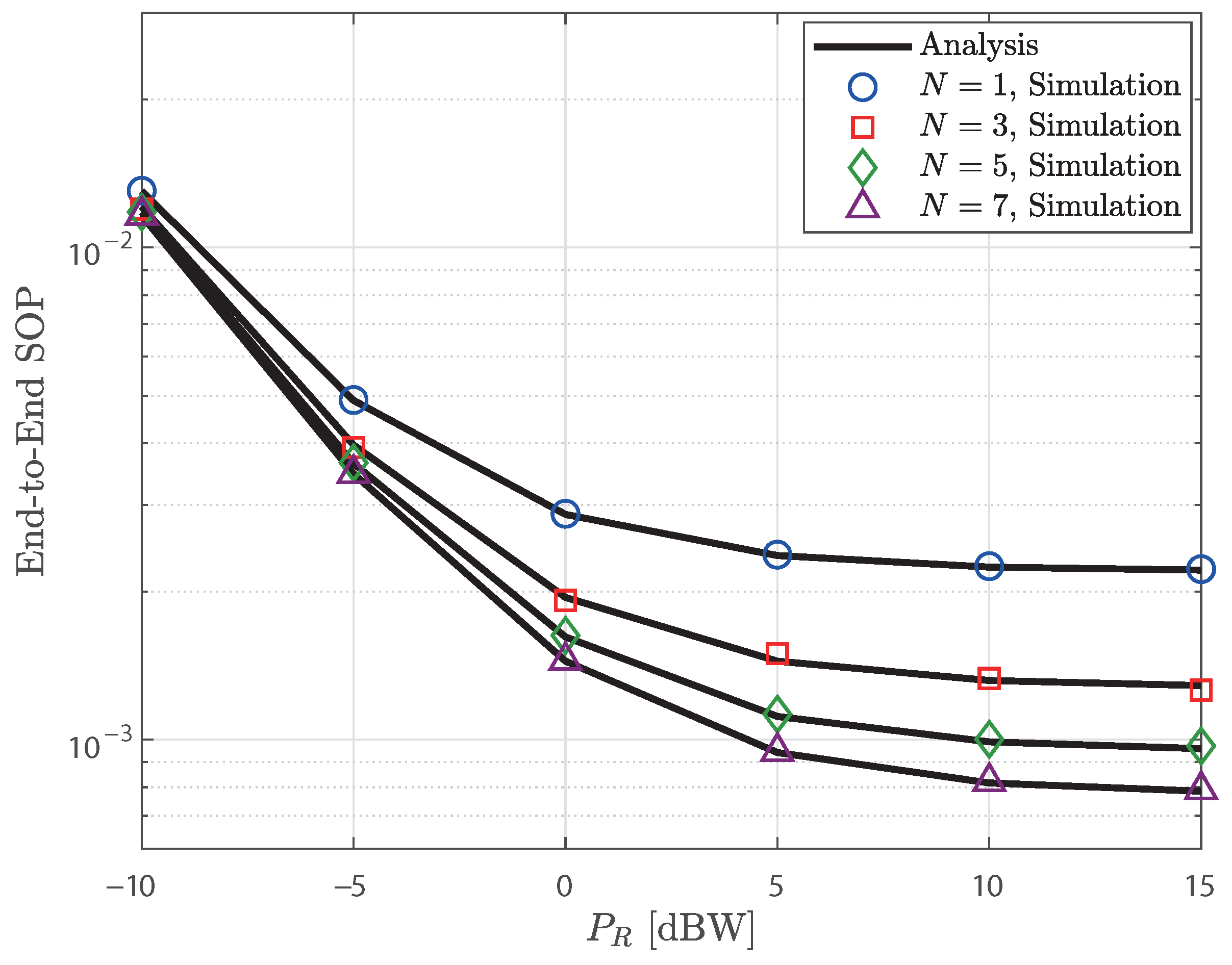
Figure 5 illustrates the variation in end-to-end secrecy break probability with relay transmission power P R under different available relay node counts ( N { 1 , 3 , 5 , 7 } ). The alignment between the analytical curve and the Monte Carlo simulation data points validates the theoretical derivation. Two primary performance trends emerge: the probability of confidentiality compromise decreases monotonically with increasing P R until saturating at a specific confidentiality threshold; overall system security significantly improves with increasing candidate relay node count N. This performance enhancement fundamentally stems from the multi-user diversity gain achieved by the opportunistic relay selection mechanism. Specifically, a larger pool of available relays statistically increases the probability of identifying an optimal intermediate node—one that maintains a robust legitimate communication channel while severely degrading the eavesdropping channel. Furthermore, the persistent lower bound on security under high-power conditions confirms that when the second-hop free-space optical link achieves near-zero interruptions, end-to-end security becomes entirely dependent on the vulnerability of the first-hop radio-frequency link.
Based on the above findings, this study provides academic and practical recommendations for deploying secure air–ground–space integrated networks. The results demonstrate that leveraging spatial diversity through relay selection constitutes an efficient physical-layer defense mechanism, offering a viable alternative to traditional power scaling approaches—which inevitably face diminishing returns due to bottleneck effects. At the engineering practice level, deploying a cooperative cluster of multiple low-cost aerial platforms as candidate relays achieves superior security enhancements compared to over-allocating transmission power to a single aerial node. To ensure communication security in high-risk environments, future network architectures should prioritize intelligent node scheduling and optimal relay selection algorithms to fully leverage the inherent spatial diversity advantages of the wireless medium.
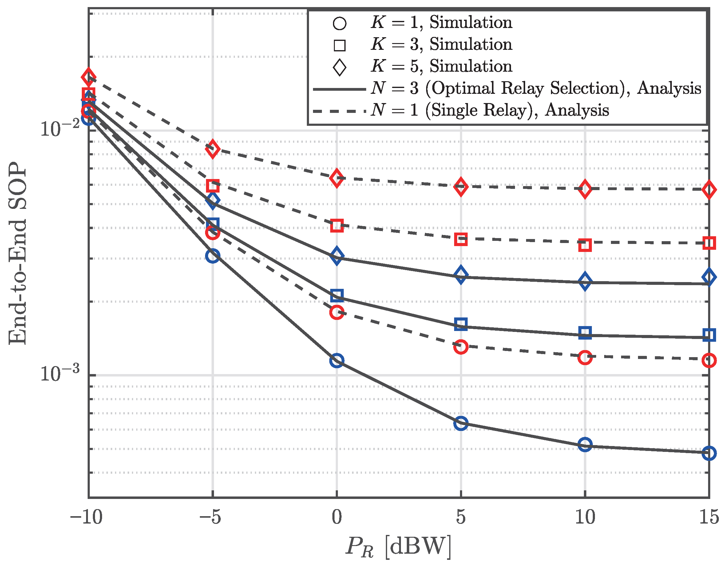
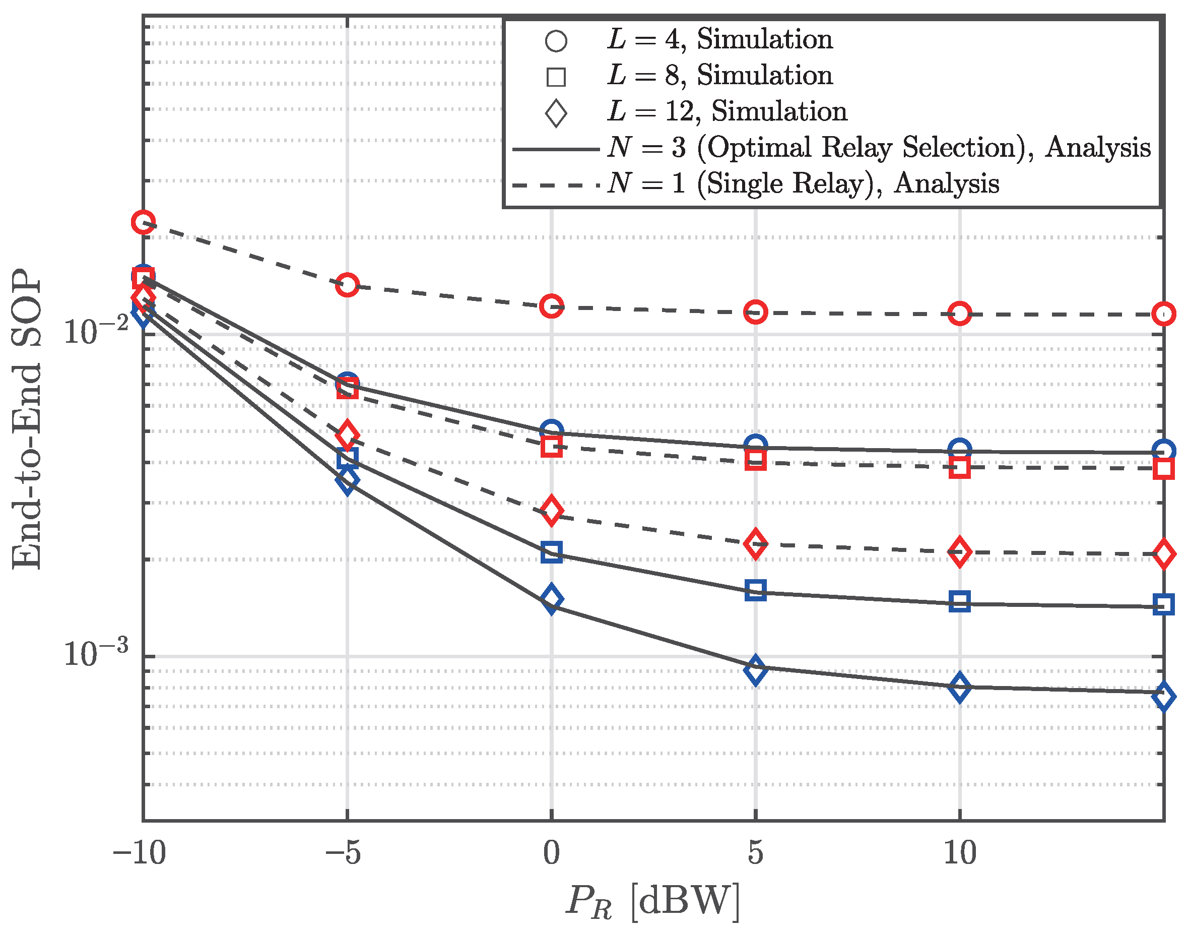
Figure 6 plots the end-to-end SOP versus P R under varying numbers of relay receiving antennas, comparing the optimal relay selection against a single-relay scheme. Validated by Monte Carlo simulations, the curves indicate that the SOP initially drops with an increase in P R before converging to a confidentiality floor. Moreover, higher L values reduce the SOP, and the proposed multi-relay scheme outperforms the single-relay configuration across the entire power regime. These reductions stem from two spatial mechanisms characteristic of the proposed SAGIN architecture. Hardware-wise, multiple antennas at the relay provide local array gain to boost the legitimate RF link quality. Algorithmically, optimal relay selection exploits the spatial degrees of freedom within the UAV cluster to bypass intercepted channels, yielding a cooperative diversity gain absent in single-relay systems.
As P R increases, all SOP curves asymptotically converge to a confidentiality lower bound, where the security gains from power amplification diminish. In this saturated regime, the end-to-end secrecy is primarily restricted by the vulnerability of the terrestrial RF link rather than the FSO backhaul. However, a vertical comparison reveals that the system can still enhance its security performance under these constrained conditions. Equipping the aerial relays with multiple receiving antennas directly increases the MRC diversity gain, while deploying a UAV swarm for optimal relay selection yields cooperative macro-diversity. These findings provide clear guidance for practical system design: relying on power scaling is inefficient, and architectures should instead prioritize spatial domain resources. Furthermore, to overcome the theoretical limits of passive diversity, future studies should explore active anti-eavesdropping countermeasures, including secure beamforming and advanced antenna technologies, to neutralize RF vulnerabilities.
Figure 7 plots the end-to-end SOP versus P R for varying eavesdropper densities, explicitly benchmarking the proposed optimal relay selection against a single-relay scheme. Validated by Monte Carlo simulations, the results demonstrate that higher K values degrade performance due to the attacker’s multi-user diversity effect; specifically, a larger K increases the probability that at least one malicious node encounters a highly favorable eavesdropping channel, thereby compromising the secure RF transmission. However, despite these escalating interception risks, the proposed cooperative scheme strictly outperforms the baseline across all regimes. This confirms that intelligently exploiting spatial degrees of freedom within the UAV cluster provides a robust geometric countermeasure, effectively leveraging legitimate cooperative diversity to offset the attacker’s advantage.
Furthermore, the secrecy floors observed in the high P R regime corroborate the bottleneck of the dual-hop DF architecture. As the FSO link interruption rate approaches zero, the end-to-end SOP becomes strictly dominated by the RF link’s vulnerability. Although optimal relay selection significantly lowers this secrecy floor compared to the baseline, the inevitable performance degradation under ultra-dense eavesdropping indicates that continuously increasing P R yields diminishing returns. Consequently, addressing severe multi-eavesdropper scenarios necessitates complementing cooperative relaying with proactive physical-layer techniques, such as artificial noise injection or RIS, to synchronously degrade distributed eavesdropping channels.
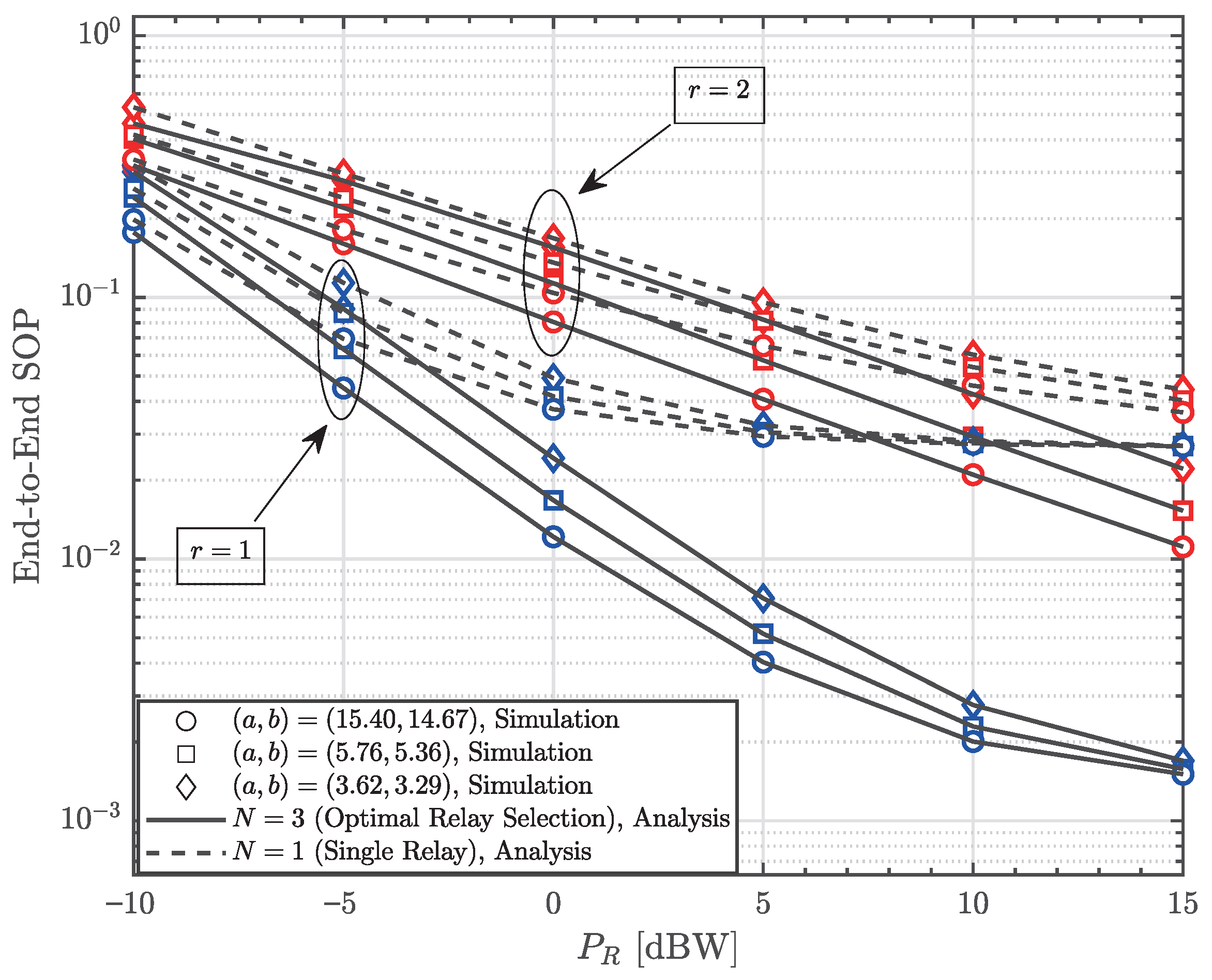
Figure 8 plots the end-to-end SOP versus P R under varying atmospheric turbulence parameters ( a , b ) and optical detection techniques (r), comparing the optimal relay selection ( N = 3 ) with a single-relay scheme ( N = 1 ). The analytical results align with the Monte Carlo simulations. The trajectories show that as P R increases, the SOP decreases and asymptotically converges to a confidentiality floor, marking the saturation of RF power gains. In the FSO domain, stronger atmospheric scintillations, characterized by smaller ( a , b ) values, consistently elevate the SOP. To mitigate this meteorological degradation, the receiver hardware plays a decisive role. The results demonstrate that heterodyne detection ( r = 1 ) yields a lower SOP than intensity modulation with direct detection (IM/DD, r = 2 ). This improvement stems from the superior receiver sensitivity of heterodyne detection, which compensates for turbulence-induced fading over the aerial backhaul.
Across all optical conditions, the proposed cooperative scheme outperforms the single-relay scheme. This confirms that spatial diversity can be provided by deploying UAV fleets and making optimal link selections, thereby bypassing compromised radio frequency channels. Because the RF secrecy floor persists despite FSO link improvements, relying on single-domain optimizations is inadequate. Deploying advanced optical detection to stabilize the FSO backhaul, coupled with multi-relay cooperative selection to secure the terrestrial access link, constructs a comprehensive physical-layer defense. This joint optical–spatial strategy safeguards the end-to-end transmission against both meteorological disturbances and ground-based interception.
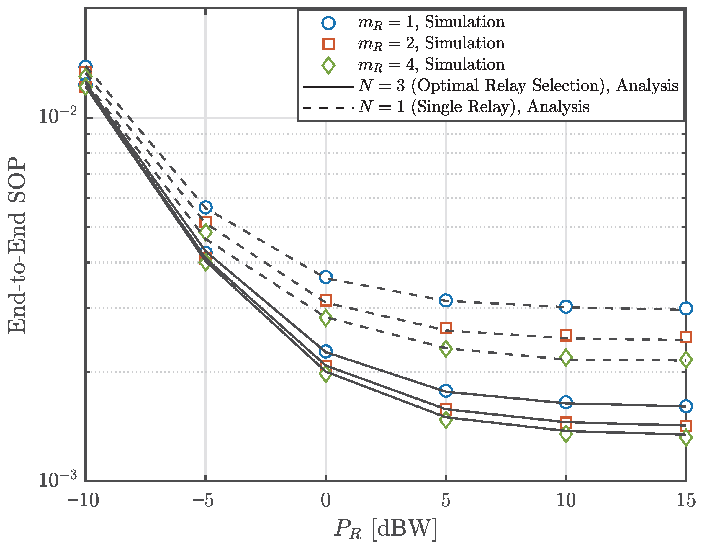
Figure 9 illustrates the end-to-end SOP versus the P R for different S-R link fading severity m R and relaying schemes. The analytical results are consistent with the Monte Carlo simulation results, confirming the accuracy of the derived expressions. As shown in the figure, the SOP decreases as m R increases, as a larger m R represents a more dominant LoS component and less severe fading.
However, by comparing different relay strategies, we found that the spatial diversity gain achieved by the proposed relay selection scheme can effectively compensate for the security degradation caused by severe channel fading. Specifically, in high P R scenarios, the SAGIN system with the relay selection scheme outperforms the single-relay baseline scheme under the worst fading conditions, even surpassing its performance under optimal fading conditions. This finding underscores that, in the two-hop SAGIN system under consideration, the opportunistic utilization of relay nodes is more critical for establishing secure links than the intrinsic quality of the propagation medium itself. This provides practical guidance for system designers: in urban environments dominated by Rayleigh fading ( m R = 1 ), deploying a moderately sized cluster of relay UAVs and performing optimal relay selection is more effective for achieving energy savings and efficient utilization of hardware resources than pursuing higher-quality single-relay links.
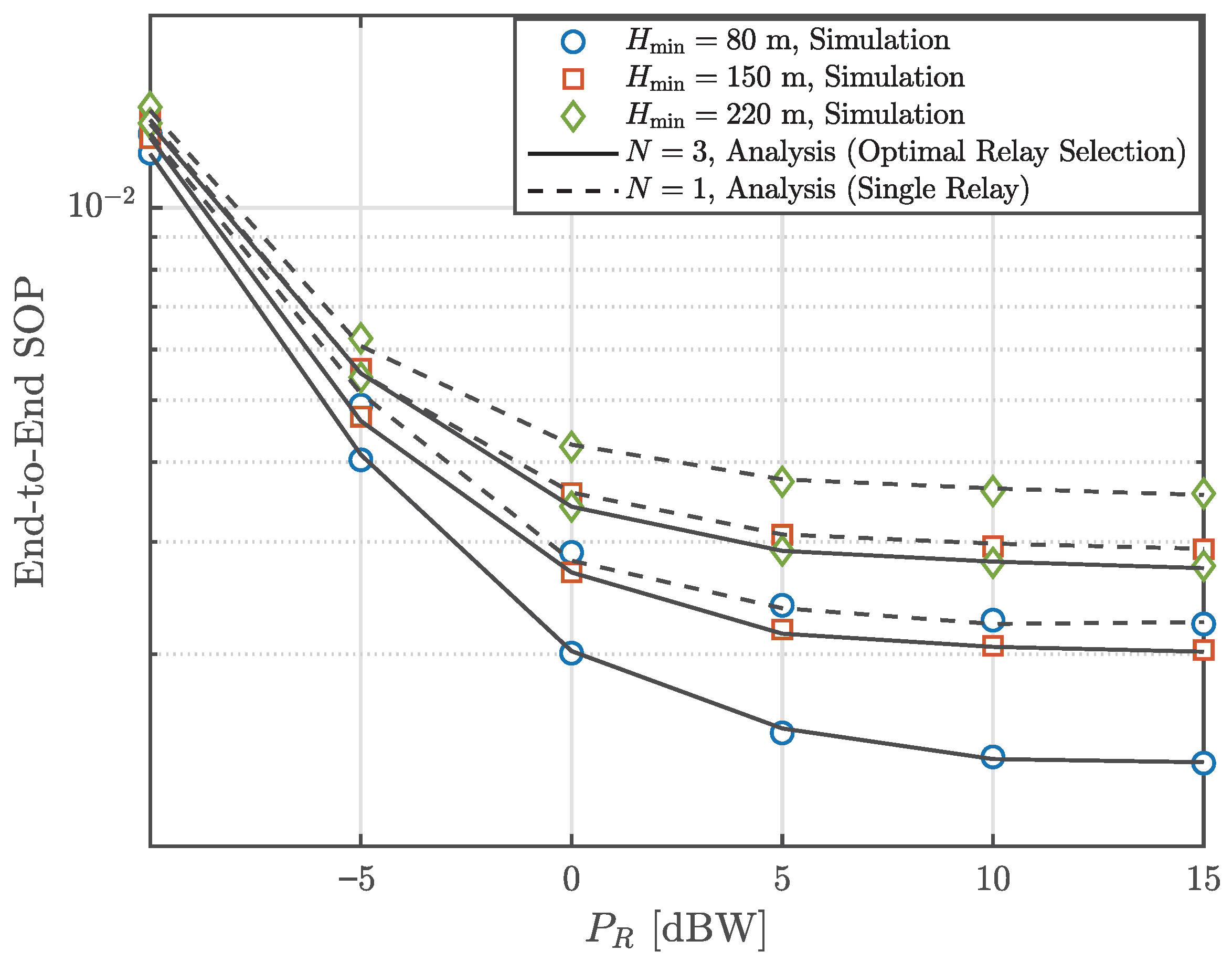
Figure 10 shows the curves of end-to-end SOP as a function of P R under different minimum hovering heights of UAVs and different relay schemes. The agreement between the analytical curves and the Monte Carlo simulation results further validates the correctness of the derivation. As can be seen from the figure, an increase in H min leads to a decline in the system’s confidentiality performance. From a geometric perspective, raising the altitude of the UAV swarm increases the minimum spatial separation between the ground source and the aerial relay. This exacerbates large-scale path loss in the valid RF links, thereby degrading the SNR at the relay and resulting in reduced communication reliability and security.
More importantly, by examining the variation in SOP across different relay schemes, we observed geometric compensation resulting from the multi-relay selection mechanism. Even when drone swarms are forced to operate at higher altitudes due to terrain constraints or aviation safety regulations, the SOP values achieved by the proposed relay selection strategy remain lower than those of the single-relay scheme, even though the single-relay scheme operates at a lower hovering altitude. This observation demonstrates in practice that spatial diversity achieved through collaborative aerial nodes can effectively offset the path loss penalty associated with high-altitude deployment. It provides robust architectural guidance for SAGIN design: deploying collaborative UAV swarms at higher, safer altitudes is safer and more reliable than having a single UAV fly at lower altitudes, closer to potential ground eavesdroppers.
Across all numerical evaluations in Figure 6, Figure 7, Figure 8, Figure 9, Figure 10, a consistent performance trend emerges: the end-to-end SOP monotonically decreases with increasing P R before saturating at a confidentiality floor. This phenomenon exposes the inherent bottleneck of the dual-hop DF architecture. Because end-to-end secrecy requires secure transmission across both hops, the FSO link outage probability approaching zero at high P R leaves the overall security bounded entirely by the vulnerability of the terrestrial RF segment. As demonstrated across varying configurations, the proposed multi-relay selection addresses this specific vulnerability by exploiting spatial degrees of freedom within the UAV cluster. This cooperative macro-diversity strictly lowers the secrecy floor compared to single-relay architectures, serving as a geometric countermeasure against terrestrial interception. However, the persistence of the confidentiality floor indicates that power scaling strategies ultimately yield diminishing returns and prove energy-inefficient for SAGIN deployments. To fully neutralize the RF bottleneck, future system designs must transition from pure power amplification to integrating active physical-layer defenses, such as artificial noise injection or RIS-assisted transmission. Concurrently, employing heterodyne detection at the FSO receiver optimizes the achievable performance limit under severe turbulence. This joint integration of advanced optical detection and spatial RF defenses establishes a secure and power-efficient cross-media communication framework.

6. Conclusions

In this paper, we investigated the PLS for the uplink of a dual-hop SAGIN. As a system innovation, we integrated a multiple-relay selection scheme among N available UAV relays to effectively mitigate interception risks from randomly distributed passive Es, while the LEO D was modeled across multi-layered orbits. Stochastic geometry was employed to capture the spatial randomness of each nodes. By leveraging the DF protocol, MRC at the optimal R, and the multiple-relay selection mechanism, exact closed-form analytical expressions for the end-to-end SOP were successfully derived over the mixed RF-FSO links.
The agreement between the Monte Carlo simulation results and the theoretical analysis confirms the validity of our derivation. The numerical results systematically revealed that while increasing N and L significantly enhances the overall PLS through multi-user and spatial diversity gains, a fundamental bottleneck effect restricts the RF-FSO architecture under high P R , resulting in an asymptotic security floor. Specifically, a transition occurs where the end-to-end performance bottleneck shifts entirely from the reliability of the FSO link to the vulnerability of the terrestrial RF link. For engineers designing satellite communication systems, the derived analytical expressions hold crucial practical significance: they provide a mathematical tool to exactly quantify this security floor. Consequently, system designers are guided to avoid energy-inefficient power scaling by selecting the optimal transmit power at the knee point of the performance curve while strategically leveraging spatial-domain resources to lower this absolute security limit. These findings provide engineering guidelines for the secure design and hardware optimization of future SAGINs. Building upon this statistical analytical framework, future work will explore the ESC, active anti-jamming strategies, and the dynamic time-varying FSO channel models driven by real-time LEO mobility and Doppler effects to further characterize the ultimate security limits in dynamic scenarios.

Author Contributions

Conceptualization, C.M.; Methodology, C.M.; Software, C.M.; Validation, C.M.; Formal analysis, Z.X.; Investigation, Z.X. and C.M.; Resources, Z.X.; Data curation, C.M.; Writing—original draft, C.M.; Visualization, C.M.; Supervision, Z.X.; Project administration, Z.X. All authors have read and agreed to the published version of the manuscript.

Funding

This research received no external funding.

Data Availability Statement

The original contributions presented in this study are included in the article. Further inquiries can be directed to the corresponding author.

Conflicts of Interest

The authors declare no conflicts of interest.

Appendix A

We assume that there are K non-colluding eavesdroppers uniformly distributed within a specific three-dimensional coverage region with a maximum radius of R S . Let d k denote the distance from the transmitter to the k-th eavesdropper, where k { 1 , 2 , , K } . Based on the assumption of uniform spatial distribution, the Cumulative Distribution Function (CDF) of a single eavesdropper’s distance d k is given by Pr { d k x } = x 3 / R S 3 .
To evaluate the worst-case secrecy scenario, we consider the most detrimental eavesdropper, which is located nearest to the transmitter. Hence, the equivalent eavesdropping distance d E is defined as the minimum among all K distances, i.e., d E = min { d 1 , d 2 , , d K } . Since the locations of the eavesdroppers are independent and identically distributed (i.i.d.), the CDF of d E , denoted by F d E ( x ) , can be derived as follows:
F d E ( x ) = Pr { min { d 1 , d 2 , , d K } x } = 1 Pr { min { d 1 , d 2 , , d K } > x } = 1 Pr { d 1 > x } Pr { d 2 > x } Pr { d K > x } = 1 k = 1 K 1 Pr { d k x } = 1 1 x 3 R S 3 K .
Subsequently, the PDF of the equivalent eavesdropper distance d E , denoted by f d E ( x ) , is obtained by taking the first-order derivative of the CDF F d E ( x ) with respect to x:
f d E ( x ) = d F d E ( x ) d x = K 1 x 3 R S 3 K 1 · 3 x 2 R S 3 = 3 K x 2 R S 3 1 x 3 R S 3 K 1 ,
where 0 x R S .

Appendix B

Similar to the eavesdropping scenario, we assume there are N candidate relays independently and uniformly distributed within a designated spatial volume V S 1 . Let d i denote the distance from the source to the i-th relay, where i { 1 , 2 , , N } . Based on the considered spherical cap geometry, the Cumulative Distribution Function (CDF) for a single relay distance d i is given by:
F i ( x ) = Pr { d i x } = π 3 V S 1 ( x H min ) 2 ( 2 x + H min ) .
By taking the first-order derivative of F i ( x ) with respect to x, the corresponding Probability Density Function (PDF) for a single relay is obtained as follows:
f i ( x ) = 2 π V S 1 x ( x H min ) .
To maximize the legitimate channel quality, the opportunistic relay selection scheme chooses the relay located closest to the source. Therefore, the equivalent relay distance is defined as d R = min { d 1 , d 2 , , d N } . Using the properties of order statistics for N independent and identically distributed (i.i.d.) variables, the CDF of the selected relay distance d R is simply formulated as follows:
F d R ( x ) = 1 1 F i ( x ) N .
Finally, taking the derivative of F d R ( x ) with respect to x and applying the chain rule, f d R ( x ) = N f i ( x ) [ 1 F i ( x ) ] N 1 , we obtain the PDF of d R as follows:
f d R ( x ) = 2 π N V S 1 x ( x H min ) 1 π 3 V S 1 ( x H min ) 2 ( 2 x + H min ) N 1 .

Appendix C

Let X = d R η 1 and Y = d E η 1 . By applying the transformation of variables to the previously derived f d R ( · ) and f d E ( · ) , and utilizing multinomial and binomial expansions, the PDFs of X and Y can be expressed in polynomial series forms. Specifically, X is bounded within [ d min , d max ] and Y is bounded within [ 0 , d max ] , where d min = H min η 1 and d max = R S η 1 .
Since X and Y are independent random variables, the PDF of their ratio Z = X / Y , denoted by f Z ( z ) , can be calculated using the standard ratio distribution integral:
f Z ( z ) = y min y max y f X ( z y ) f Y ( y ) d y .
The critical step in evaluating Equation (A7) is determining the exact integration limits for y. Given that X = z y , the integration variable y must simultaneously satisfy the domains of both X and Y, leading to the following inequalities:
0 y d max and d min z y d max .
Therefore, if d min d max z 1 , substituting (26) and (21) into (A7) yields:
F Z ( z ) = k = 0 N 1 m = 0 2 k + 1 n = 0 k j = 0 K 1 C k , m , n , j d max Λ · z α 1 d min Λ · z β j 1 ,
where C k , m , n , j , Λ , α and β j are shown in (28).
Similarly, when z > 1 , substituting (26) and (21) into (A7) and performing operations on different integration intervals yields:
F Z ( z ) = k = 0 N 1 m = 0 2 k + 1 n = 0 k j = 0 K 1 C k , m , n , j d max Λ d min Λ · z β j 1 ,
Thus, we can derive the PDF of Z as in (28).

Appendix D

Based on the definition of the secrecy outage probability for the RF link, SOP 1 is formulated as follows:
SOP 1 = Pr P S h S R 2 N R d R η 1 λ P S h S E * 2 N E d E η 1 + λ 1 ,
where λ = 2 C th . Since C th > 0 , we have λ > 1 . By omitting the positive constant term ( λ 1 ) , a tight lower bound SOP 1 L is established as follows:
SOP 1 L = Pr h S R 2 a 0 Z h S E * 2 ,
where a 0 = λ N R N E (incorporating the channel scale parameter λ R if normalized) and Z = d R η 1 / d E η 1 .
Let X = h S E * 2 . Assuming the legitimate channel and the wiretap channel experience independent Gamma fading, the CDF of h S R 2 and the PDF of X are given by standard Gamma distributions with shape parameters L m R and m E , respectively. By conditioning on Z and taking the expectation over X, SOP 1 L is expressed as follows:
SOP 1 L = ρ Z 0 F h S R 2 ( a 0 z x ) f X ( x ) d x f Z ( z ) d z = 1 l = 0 L m R 1 l + m E 1 l ρ Z a 0 z a 0 z + λ E l λ E a 0 z + λ E m E f Z ( z ) d z ,
where λ E is the scale parameter of the eavesdropping channel, and ρ Z = ( H min / R S ) η 1 is the lower bound of Z.
Due to the piecewise nature of f Z ( z ) derived in Appendix C, the integration over Z in Equation (A13) must be bifurcated into two distinct intervals: z [ ρ Z , 1 ] and z ( 1 , ) .
If z [ ρ Z , 1 ] , we substitute the corresponding part of f Z ( z ) and evaluate the integral. By factoring out λ E from the denominator, the core integral structure takes the form z μ 1 ( 1 + a 0 λ E z ) ( l + m E ) d z . Using the integral representation of the hypergeometric function, we define an auxiliary function:
F ( x , μ ) = x μ μ F 1 2 l + m E , μ ; μ + 1 ; a 0 λ E x .
Applying F ( x , μ ) to the upper and lower limits with respect to the exponents μ = l + α and μ = l β j , we obtain the first integrated term T 1 :
T 1 = a 0 λ E l d max Λ · Δ F A d min Λ · Δ F B ,
where Δ F A = F ( 1 , l + α ) F ( ρ Z , l + α ) and Δ F B = F ( 1 , l β j ) F ( ρ Z , l β j ) .
If z ( 1 , ) , we substitute the z > 1 portion of f Z ( z ) . To resolve the integration extending to infinity, we apply the variable substitution u = 1 / z , which maps the integration domain from ( 1 , ) to ( 0 , 1 ) . This transformation reconfigures the algebraic terms, naturally leading to a standard integral form of the hypergeometric function evaluated at λ E a 0 . The resulting term T 2 is strictly derived as follows:
T 2 = λ E a 0 m E d max Λ d min Λ β j + m E F 1 2 l + m E , β j + m E ; β j + m E + 1 ; λ E a 0 .
Finally, by summing the constants C k , m , n , j and the integrated terms T 1 and T 2 over their respective indices, the exact closed-form expression for the lower bound is obtained as follows:
SOP 1 L = 1 l = 0 L m R 1 l + m E 1 l k = 0 N 1 m = 0 2 k + 1 n = 0 k j = 0 N 1 C k , m , n , j T 1 + T 2 .
Therefore, the expression for SOP1L is obtained as in (32).

Appendix E

The outage probability of the first hop, denoted as OP 1 , is defined as the probability that the instantaneous signal-to-noise ratio (SNR) at the selected relay falls below a predefined decoding threshold γ out . Mathematically, this is expressed as follows:
OP 1 = Pr ( γ R < γ out ) = Pr P S h S R 2 N R d R η 1 γ out .
By isolating the legitimate channel gain h S R 2 , the probability can be rewritten as follows:
OP 1 = Pr h S R 2 γ out N R P S d R η 1 .
Let x = d R η 1 . By conditioning on the random variable x, OP 1 can be evaluated by integrating the Cumulative Distribution Function (CDF) of h S R 2 over the exact Probability Density Function (PDF) of x, yielding:
OP 1 = H min η 1 R S η 1 F h S R 2 γ out N R P S x f d R η 1 ( x ) d x .
Assuming the legitimate RF link undergoes Nakagami-m fading, the channel gain h S R 2 follows a Gamma distribution with shape parameter m R . Its CDF can be formulated using the finite series expansion as follows:
F h S R 2 ( y ) = 1 q = 0 m R 1 ( λ R y ) q q ! exp ( λ R y ) ,
where λ R denotes the scale parameter of the legitimate channel. Substituting Equation (A21) and the previously derived polynomial expansion of f d R η 1 ( x ) into Equation (A20), the integral expands as follows:
OP 1 = H min η 1 R S η 1 1 q = 0 m R 1 ( μ x ) q q ! exp ( μ x ) k = 0 N 1 m = 0 2 k + 1 n = 0 k Φ k , m , n x τ 1 d x = H min η 1 R S η 1 f d R η 1 ( x ) d x k = 0 N 1 m = 0 2 k + 1 n = 0 k Φ k , m , n q = 0 m R 1 μ q q ! H min η 1 R S η 1 x q + τ 1 exp ( μ x ) d x ,
where μ = λ R γ out N R P S incorporates the system constants, and the exponent parameter is defined as τ = 3 k m n + 3 η 1 .
Recognizing that the integral of a valid PDF over its entire support mathematically equates to 1, the first term simplifies to unity. To rigorously resolve the remaining definite integral, we invoke the standard definition of the lower incomplete gamma function [30] (Equation (8.350.1)), defined as follows:
γ ( s , y ) = 0 y t s 1 e t d t .
Specifically, by applying the linear variable transformation t = μ x to match the integration kernel, the integral is explicitly evaluated in closed form, yielding the exact solution scaled by the factor μ ( q + τ ) .
Notice that the μ q term outside the integral cancels with a portion of the μ ( q + τ ) scaling factor, leaving exactly μ τ . By consolidating the remaining constant terms and the evaluated incomplete gamma functions, we derive the exact closed-form expression for OP 1 as in (38).

Appendix F

As the LEO satellites are distributed across two orbital layers, we define the area of each corresponding spherical cap as A i = 2 π r D i 2 ( 1 cos Ψ D i ) for i { 1 , 2 } . With the total active area denoted by A total = A 1 + A 2 , the probability of the destination residing on the i-th cap is given by:
Pr ( A i ) = A i A total = 2 π r D i 2 ( 1 cos Ψ D i ) A total .
Assuming the satellites are uniformly distributed over the spherical caps, the probability of finding a satellite within a differential solid angle yields the PDF of the zenith angle θ [ 0 , Ψ D i ] . By normalizing the differential area element 2 π r D i 2 sin θ d θ by the cap area A i , the PDF of θ is explicitly formulated as f ( θ ) = sin θ 1 cos Ψ D i .
Given that the destination resides on cap A i , the squared distance w = d D 2 can be geometrically expressed using the law of cosines as w = r D i 2 + H R 2 2 r D i H R cos θ , where H R is the aerial relay altitude. By applying the variable transformation f ( w ) = f ( θ ) d θ d w with the derivative d w = 2 r D i H R sin θ d θ , the sin θ terms perfectly cancel out, yielding a uniform conditional PDF for the squared distance:
f d D i 2 | A i ( w ) = 1 2 r D i H R ( 1 cos Ψ D i ) ,
which is valid for w W i = [ w i , min , w i , max ] . Here, the boundaries are physically constrained by the satellite elevation angles as w i , min = ( r D i H R ) 2 and w i , max = r D i 2 + H R 2 2 r D i H R cos Ψ D i .
Using the law of total probability, the unconditional PDF of the squared distance w is the weighted sum of the conditional distributions:
f d D 2 ( w ) = Pr ( A 1 ) f d D 1 2 | A 1 ( w ) + Pr ( A 2 ) f d D 2 2 | A 2 ( w ) .
Substituting the derived expressions into the above, the amplitude of each weighted conditional PDF simplifies to π r D i H R A total . To facilitate a compact representation, we define an auxiliary constant K = H R A total π = 2 H R r D 1 2 ( 1 cos Ψ D 1 ) + r D 2 2 ( 1 cos Ψ D 2 ) . Thus, the amplitude contribution from each orbital layer i is exactly r D i / K .
Finally, depending on the orbital altitudes and the maximum zenith angles, the physical distance intervals W 1 and W 2 may partially overlap. By sorting the boundary points { w 1 , min , w 1 , max , w 2 , min , w 2 , max } into an ordered set, the total domain is segmented into non-overlapping sub-intervals. By summing the active amplitudes r D i / K within each respective sub-interval, the exact piecewise PDF of w is systematically obtained as in (41).

Appendix G

According to (42), assuming the FSO link experiences Gamma–Gamma atmospheric turbulence with pointing errors, the conditional outage probability for a given squared transmission distance w = d D 2 can be formulated using the Meijer-G function as follows:
Pr γ D < γ out 2 w = I G r + 1 , 3 r + 1 3 r , 1 ϵ w | 1 , K 1 K 2 , 0 ,
where ϵ is defined as follows:
ϵ = 4 π f c σ d 2 h a b r P R c 2 ζ 2 L r 2 r 2 r γ out 2 .
We average the conditional probability in Equation (A27) over the exact PDF of the squared FSO link distance f d D 2 ( w ) derived in Appendix F. By invoking the law of total probability, OP 2 is expressed as follows:
OP 2 = 0 Pr γ D < γ out 2 w f d D 2 ( w ) d w .
Since f d D 2 ( w ) is a piecewise constant function, by applying the standard integral identity of the Meijer-G function, we define a bounded integral function G int ( m , n ) , whose computational range extends from the lower bound n to the upper bound m as follows:
G int ( m , n ) = G r + 2 , 3 r + 2 3 r , 2 ϵ m | 1 , 2 , K 1 + 1 K 2 + 1 , 0 , 1 G r + 2 , 3 r + 2 3 r , 2 ϵ n | 1 , 2 , K 1 + 1 K 2 + 1 , 0 , 1 .
Applying the above formula to different integration intervals, we obtain the expression for OP 2 as in (43).

References

  1. Li, T.; Ye, J.; Dai, J.; Lei, H.; Yang, W.; Pan, G.; Chen, Y. Secure UAV-to-Vehicle Communications. IEEE Trans. Commun. 2021, 69, 5381–5393. [Google Scholar] [CrossRef]
  2. Li, H.; Li, J.; Liu, M.; Gong, F. UAV-Assisted Secure Communication for Coordinated Satellite-Terrestrial Networks. IEEE Commun. Lett. 2023, 27, 1709–1713. [Google Scholar] [CrossRef]
  3. Alqurashi, F.S.; Abdeljabar, S.; Trichili, A.; Alouini, M.S. Overcoming Maritime Connectivity Challenges with Hybrid RF/FSO Links. In Proceedings of the 2024 IEEE Globecom Workshops (GC Wkshps), Cape Town, South Africa, 8–12 December 2024; pp. 1–6. [Google Scholar] [CrossRef]
  4. Jamshed, M.A.; Kaushik, A.; Dajer, M.; Guidotti, A.; Parzysz, F.; Lagunas, E.; Di Renzo, M.; Chatzinotas, S.; Dobre, O.A. Non-Terrestrial Networks for 6G: Integrated, Intelligent, and Ubiquitous Connectivity. IEEE Commun. Stand. Mag. 2025, 9, 86–93. [Google Scholar] [CrossRef]
  5. Im, G.; Ryu, J.G. UAV-Relay-Assisted LEO Satellite Communication Systems with Cooperative Non-Orthogonal Multiple Access. In Proceedings of the 2025 16th International Conference on Information and Communication Technology Convergence (ICTC), Jeju, Republic of Korea, 14–17 October 2025; pp. 2086–2089. [Google Scholar] [CrossRef]
  6. Zheng, X.; Wu, Y.; Fan, L.; Lei, X.; Qingyang Hu, R.; Karagiannidis, G.K. Dual-Functional UAV-Empowered Space-Air-Ground Networks: Joint Communication and Sensing. IEEE J. Sel. Areas Commun. 2024, 42, 3412–3427. [Google Scholar] [CrossRef]
  7. Yao, Y.; Xiao, W.; Miao, P.; Chen, G.; Yang, H.; Chae, C.B.; Wong, K.K. UAV-Relay-Aided Secure Maritime Networks Coexisting With Satellite Networks: Robust Beamforming and Trajectory Optimization. IEEE Trans. Wireless Commun. 2026, 25, 2342–2358. [Google Scholar] [CrossRef]
  8. Senadhira, N.; Durrani, S.; Guo, J.; Yang, N.; Zhou, X. Design and Performance Analysis of UAV-Assisted Maritime-LEO Satellite Communication Networks. IEEE Open J. Commun. Soc. 2025, 6, 4667–4688. [Google Scholar] [CrossRef]
  9. Bhola; Chen, Y.J.; Balakrishnan, A.; De, S.; Wang, L.C. Cooperative UAV-Relay based Satellite Aerial Ground Integrated Networks. In Proceedings of the 2024 IEEE 100th Vehicular Technology Conference (VTC2024-Fall), Washington, DC, USA, 7–10 October 2024; pp. 1–5. [Google Scholar] [CrossRef]
  10. Talgat, A.; Wang, R.; Kishk, M.A.; Alouini, M.S. Enhancing Physical-Layer Security in LEO Satellite-Enabled IoT Network Communications. IEEE Internet Things J. 2024, 11, 33967–33979. [Google Scholar] [CrossRef]
  11. Qian, L.P.; Fan, X.; Li, M.; Wu, Y. Energy-Efficient Data Gathering and Computing in LEO Satellite-Assisted Marine IoT Networks. IEEE Trans. Cogn. Commun. Netw. 2026, 12, 1933–1947. [Google Scholar] [CrossRef]
  12. Mamun, Q.; Ho, T.D.; Pan, Z.; Shimamoto, S. SkyLock: A Unified Multi-Layer Authentication and Key Management Framework for 6G Non-Terrestrial Networks. In Proceedings of the 2026 IEEE 23rd Consumer Communications & Networking Conference (CCNC), Las Vegas, NV, USA, 9–12 January 2026; pp. 1–6. [Google Scholar] [CrossRef]
  13. Zhang, Y.; Zang, B.; Li, L.; Ji, H.; Li, S. Addressing Spoofing and Unauthorized Access: DL-Based Satellite Physical-Layer Authentication. In Proceedings of the 2025 IEEE Wireless Communications and Networking Conference (WCNC), Milan, Italy, 24–27 March 2025; pp. 1–6. [Google Scholar] [CrossRef]
  14. Crosara, L.; Ardizzon, F.; Laurenti, N.; Caparra, G. Security Protection Levels for GNSS PVT Assurance with a 5G NTN LEO Satellite. In Proceedings of the 2024 11th Workshop on Satellite Navigation Technology (NAVITEC), Noordwijk, The Netherlands, 11–13 December 2024; pp. 1–4. [Google Scholar] [CrossRef]
  15. Li, J.; Li, X.; Li, C.; Wang, C.; He, J. A Review of LEO Satellite Network Security Research. In Proceedings of the 2023 2nd International Conference on Data Analytics, Computing and Artificial Intelligence (ICDACAI), Zakopane, Poland, 17–19 October 2023; pp. 496–501. [Google Scholar] [CrossRef]
  16. Hasan, M.S.; Ishak, M.G.; Moon, J. Secrecy Enhancement and Distributed Architectures in LEO Satellite Networks: A Survey on AN-Assisted Scheduling and SUSDA Design. In Proceedings of the 2025 16th International Conference on Information and Communication Technology Convergence (ICTC), Jeju, Republic of Korea, 14–17 October 2025; pp. 1307–1312. [Google Scholar] [CrossRef]
  17. Hao, Y.; Wang, W.; Liu, T.; Li, Y.; Li, Y.; Zhao, Y.; Huang, S.; Xu, K.; Zhang, J. Joint Load Balancing of Bandwidth and Security Resources in Optical Satellite Networks. In Proceedings of the 2024 IEEE Globecom Workshops (GC Wkshps), Cape Town, South Africa, 8–12 December 2024; pp. 1–6. [Google Scholar] [CrossRef]
  18. Jiang, B.; Yan, Y.; You, L.; Wang, J.; Wang, W.; Gao, X. Robust Secure Transmission for Satellite Communications. IEEE Trans. Aerosp. Electron. Syst. 2023, 59, 1598–1612. [Google Scholar] [CrossRef]
  19. Shi, Y.; Luo, Q.; Zhang, S.; Wang, J.; Liu, J. Jamming Scheduling and Resource Allocation for Secure Communication in Massive LEO Satellite-Empowered IoT Network. IEEE Internet Things J. 2026, 13, 9849–9860. [Google Scholar] [CrossRef]
  20. Qin, Z.; Zhang, Z.; Zhang, T. Robust Beamforming with UAV-Assisted Artificial Noise for Secure LEO Communications. In Proceedings of the 2025 IEEE 102nd Vehicular Technology Conference (VTC2025-Fall), Chengdu, China, 19–22 October 2025; pp. 1–5. [Google Scholar] [CrossRef]
  21. Ibrahim, M.; Islam Sarkar, M.Z.; Abdur Rakib, M. Evaluating Physical Layer Security in Dual-Hop Relay Networks over Composite Rayleigh-Gamma Fading Channels. In Proceedings of the 2025 International Conference on Electrical, Computer and Communication Engineering (ECCE), Chittagong, Bangladesh, 13–15 February 2025; pp. 1–5. [Google Scholar] [CrossRef]
  22. Wang, X.; Xu, G.; Dong, Y.; Gao, M.; Zhang, Q.; Song, Z. Secrecy Outage Probability of RF/FSO System for Hybrid Satellite-Terrestrial Relay Network. In Proceedings of the 2023 International Conference on Microwave and Millimeter Wave Technology (ICMMT), Qingdao, China, 14–17 May 2023; pp. 1–3. [Google Scholar] [CrossRef]
  23. Zedini, E.; Ansari, I.S.; Alouini, M.S. Performance Analysis of Mixed Nakagami-m and Gamma-Gamma Dual-Hop FSO Transmission Systems. IEEE Photon. J. 2015, 7, 7900120. [Google Scholar] [CrossRef]
  24. Wang, D.; Wu, M.; Wei, Z.; Yu, K.; Min, L.; Mumtaz, S. Uplink Secrecy Performance of RIS-Based RF/FSO Three-Dimension Heterogeneous Networks. IEEE Trans. Wireless Commun. 2024, 23, 1798–1809. [Google Scholar] [CrossRef]
  25. Kumar, R.; Shukla, M.K.; Kumar, V.; Tripathi, R. UAV-Enabled SAGIN: Investigating Multi-RIS Systems for Mixed FSO-RF Communication. IEEE Trans. Aerosp. Electron. Syst. 2026, 62, 1107–1118. [Google Scholar] [CrossRef]
  26. Ma, Y.; Lv, T.; Pan, G.; Chen, Y.; Alouini, M.S. On Secure Uplink Transmission in Hybrid RF-FSO Cooperative Satellite-Aerial-Terrestrial Networks. IEEE Trans. Commun. 2022, 70, 8244–8257. [Google Scholar] [CrossRef]
  27. Fidele Adanvo, V.; Mafra, S.; Montejo-Sánchez, S.; Augusto Tondo, F.; Demo Souza, R. Analytical Modeling of Slotted Aloha-Based Direct-to-Satellite-IoT Sensor Networks Over Nakagami-m Fading Channels. IEEE Sens. J. 2026, 26, 3264–3277. [Google Scholar] [CrossRef]
  28. Li, J.; Sun, G.; Sun, Z.; Wang, J.; Liu, Y.; Zhang, R.; Niyato, D.; Mao, S. LLM-Guided DRL for Multi-Tier LEO Satellite Networks with Hybrid FSO/RF Links. IEEE J. Sel. Areas Commun. 2026, 44, 2393–2410. [Google Scholar] [CrossRef]
  29. Li, Q.; El-Hajjar, M.; Cao, K.; Xu, C.; Haas, H.; Hanzo, L. Holographic Metasurface-Based Beamforming for Multi-Altitude LEO Satellite Networks. IEEE Trans. Wireless Commun. 2025, 24, 3103–3116. [Google Scholar] [CrossRef]
  30. Gradshteyn, I.S.; Ryzhik, I.M. Table of Integrals, Series, and Products, 7th ed.; Elsevier/Academic Press: Amsterdam, The Netherlands, 2007. [Google Scholar]
  31. Savita, A.K.; Jaiswal, A. Performance and Complexity Analysis of RSMA in Asymmetric Mixed FSO/mmWave-RF Systems. IEEE Trans. Commun. 2026, 74, 3223–3238. [Google Scholar] [CrossRef]
  32. Tang, J.; Xia, L.; Wei, C.; Wang, H.; Mahapatra, R. Guided Open-Loop System for Deep Space Doppler Tracking. IEEE Trans. Circuits Syst. II Exp. Briefs 2024, 71, 3343–3347. [Google Scholar] [CrossRef]
  33. Gao, M.; Xu, G.; Song, Z.; Zhang, Q.; Zhang, W. Performance Analysis of LEO Satellite-Assisted Deep Space Communication Systems. IEEE Trans. Aerosp. Electron. Syst. 2025, 61, 12628–12648. [Google Scholar] [CrossRef]
  34. Patel, A.; Prakriya, S. Secrecy Performance of Energy Harvesting Cooperative Network With Power Control. IEEE Trans. Green Commun. Netw. 2026, 10, 2147–2163. [Google Scholar] [CrossRef]
  35. Kim, Y.; Yoon, D. Moment-Based Estimation for Gamma-Gamma Fading Parameters in Free-Space Optical Links. IEEE J. Sel. Areas Commun. 2025, 43, 1582–1589. [Google Scholar] [CrossRef]
  36. Rani, R.; Jayanthi, N.; Mandpura, A.K. Power Allocation and CAR Optimization in Multiuser Dual-Hop RF/FSO DF Relaying Systems With Channel Estimation Error. IEEE Trans. Green Commun. Netw. 2025, 9, 1513–1523. [Google Scholar] [CrossRef]
  37. Ruby, R.; ElHalawany, B.M.; Pham, Q.V.; Wu, K.; Wang, L. Impact of UAV-Based Transmitter Mobility on Physical Layer Security. IEEE Trans. Inf. Forensics Secur. 2025, 20, 5604–5619. [Google Scholar] [CrossRef]
  38. Bloch, M.; Barros, J.; Rodrigues, M.R.D.; McLaughlin, S.W. Wireless Information-Theoretic Security. IEEE Trans. Inf. Theory 2008, 54, 2515–2534. [Google Scholar] [CrossRef]
Figure 1. System model of cooperative dual-hop SAGIN.
Aerospace 13 00341 g001
Figure 2. First-hop link model.
Aerospace 13 00341 g002
Figure 3. Second-hop link model.
Aerospace 13 00341 g003
Figure 4. End-to-end SOP versus the P R for different values of Ψ S .
Aerospace 13 00341 g004
Figure 5. End-to-end SOP versus the P R for different values of N.
Aerospace 13 00341 g005
Figure 6. End-to-end SOP versus the P R for different values of L.
Aerospace 13 00341 g006
Figure 7. End-to-end SOP versus the P R for different values of K.
Aerospace 13 00341 g007
Figure 8. End-to-end SOP versus the P R for different values of a ,   b and r.
Aerospace 13 00341 g008
Figure 9. End-to-end SOP versus the P R for different values of m R .
Aerospace 13 00341 g009
Figure 10. End-to-end SOP versus the P R for different values of H m i n .
Aerospace 13 00341 g010
Table 1. Summary of main notations.
SymbolDefinition
S , R i , D , E k Source, i-th aerial relay, LEO destination, and k-th eavesdropper
N , K Total number of available aerial relays and terrestrial eavesdroppers
LNumber of receiving antennas equipped at each aerial relay
P S , P R Transmit power of the terrestrial source and the selected relay
R S , H min Radius of the terrestrial coverage area and minimum UAV hovering altitude
η 1 Path-loss exponent for the terrestrial RF links
m q , Ω q Nakagami-m fading severity and average channel gain for RF link q
a , b Gamma-Gamma atmospheric turbulence parameters for the FSO link
rDetection technique parameter ( r = 1 for HD, r = 2 for IM/DD)
ξ Pointing error parameter of the FSO link
γ o u t 1 Predefined decoding SNR threshold at the relay
γ o u t 2 Predefined decoding SNR threshold at the destination
C t h Target secrecy capacity threshold
Table 2. Main simulation parameters (default values and variable ranges).
SymbolParameter DescriptionDefault Value (Tested Range)
P S Transmit power at the source10 dBW
R S Radius of the source coverage area300 m
H min Minimum UAV hovering altitude80 m (Varies in { 80 , 150 , 220 } )
η 1 Path loss exponent 2.1
m R , Ω R Nakagami-m fading parameters for S-R link 2 , 1.9
m E , Ω E Nakagami-m fading parameters for S-E link 1 , 0.5
N R , N E Noise power at the R and E1 W
C t h Target secrecy capacity threshold 0.01 bits/s/Hz
R E a r t h Radius of the Earth6371 km
H D 1 , H D 2 Orbital altitudes of the satellite550 km, 600 km
Ψ R Divergence angle of the FSO beam π / 12
ξ Pointing error parameter 1.1
L r FSO link overall gain81 dB
LNumber of antennas at the relay8 (Varies in { 4 , 8 , 12 } )
NNumber of relays3 (Varies in { 1 , 3 , 5 , 7 } )
KNumber of eavesdroppers3 (Varies in { 1 , 3 , 5 } )
Ψ S Coverage angle of the source π / 6 (Varies in { π / 24 , π / 12 , π / 6 })
rOptical detections1 or 2
a , b Gamma-Gamma turbulence parameters15.40, 14.67 (Varies in {(5.76, 5.36), (3.62, 3.29)})
Disclaimer/Publisher’s Note: The statements, opinions and data contained in all publications are solely those of the individual author(s) and contributor(s) and not of MDPI and/or the editor(s). MDPI and/or the editor(s) disclaim responsibility for any injury to people or property resulting from any ideas, methods, instructions or products referred to in the content.