Article

A Supersonic Compressor Cascade Aerodynamic Design and Optimization Methodology with Curvature Control
1
School of Intelligent Manufacturing and Equipment, Shenzhen University of Information Technology, Shenzhen 518172, China
2
School of Energy Science and Engineering, Harbin Institute of Technology, Harbin 150001, China
*
Author to whom correspondence should be addressed.
Aerospace 2026, 13(3), 248; https://doi.org/10.3390/aerospace13030248

Submission received: 23 December 2025 / Revised: 27 February 2026 / Accepted: 5 March 2026 / Published: 6 March 2026
(This article belongs to the Section Aeronautics)

Abstract

Addressing the issue of boundary layer separation and flow instability caused by shock wave–boundary layer interaction in supersonic compressor cascades, this work presents a novel aerodynamic design and optimization method for supersonic cascades. This method is based on a design philosophy of enhancing control over the shock wave and boundary layer by employing a blade channel with a curvature-continuous profile. An aerodynamic redesign and optimization methodology was conducted on the ARL-SL19 supersonic cascade, aiming to improve its aerodynamic performance and widen the stable operating range. The results indicate that for a low-loss diffusing channel, the design principle for the suction surface profile involves controlling the shock strength via the curvature of the forward section, while the aft section should feature a smooth and negative curvature variation. This approach facilitates the control of the boundary layer flow, thereby improving the overall aerodynamic performance of the supersonic cascade. Compared to the baseline, the aerodynamically optimized cascade demonstrates a 10.74% reduction in the total pressure loss coefficient at the design point. Furthermore, its performance at off-design conditions is also significantly enhanced: the near-stall total pressure loss coefficient is reduced by 6.66%, the maximum total pressure ratio is increased by 6.32%, and the stable operating range with low flow loss is considerably extended.

1. Introduction

High efficiency, high load capacity, and high reliability have consistently represented fundamental objectives and developmental directions in aero-engine design technology. As the key aerodynamic component of an aero-engine, the performance of the compressor directly influences the overall economy and operational stability of the engine system. Consequently, the development of high-performance compressors remains a forefront research topic and focal point within this field. High loading inherently implies high blade tip tangential velocities within compressor passages. High load capacity means that the compressor channel has a high blade tip tangential speed, and the high-Mach-number flow completes the energy conversion process in a complex environment with strong adverse pressure gradients, shock waves, and boundary layer separation [1,2]. The effective management of these flow features is paramount for further enhancing the performance of highly loaded compressors while simultaneously constituting the primary technical challenge in realizing efficient, high-loading designs [3,4,5]. Serving as the structural backbone of three-dimensional blades, the element blade airfoil design governs the aerodynamic performance of the blade passage at the fundamental aerodynamic levels. As a fundamental model representing the passage flow in transonic compressors and serving as the geometric backbone for blade design, the supersonic diffusing cascade has garnered significant attention and extensive research from scholars and engineers [6,7,8,9,10,11,12,13]. International research includes Levine’s [14] fundamental investigation into supersonic cascade flow, which revealed the unique incidence characteristic of supersonic diffusing cascades. This work was subsequently systematized by Lichtfuss [15], who formalized the corresponding calculation method termed the “Levine Method”. Wennerstrom and Frost [16], through the analysis of flow characteristics within supersonic compressor cascade passages, proposed a design philosophy of an “S-shaped” airfoil geometry tailored to better match the internal flow, leading to the development of the ARL-SL19 cascade. Piovesan [17] analyzed the impact of solidity on the aerodynamic performance of the ARL-SL19 cascade, demonstrating that increased solidity effectively reduces total pressure loss. Meanwhile, scholars in China have also conducted extensive research on supersonic cascade design techniques. Qiu et al. [18] proposed a parametric method utilizing four second-order Bezier curves to construct the suction surface profile, subsequently generating the full airfoil geometry by superimposing a thickness distribution; however, this approach only guarantees C1 continuity. Cui et al. [19] employed numerical simulation to analyze the influence of cascade design parameters on aerodynamic performance. Zhang et al. [20], based on a direct passage control modeling approach, investigated the effects of throat area ratio, throat location, and solidity on the minimum loss point performance of supersonic diffusing cascades. Sun et al. [21] studied solidity’s impact on supersonic cascade aerodynamic performance, identifying optimal solidity values that significantly reduced wake losses. Zhang et al. [22] utilized computational fluid dynamics (CFD) to confirm the hysteresis phenomenon occurring during supersonic cascade startup and analyzed its underlying flow mechanisms. Li et al. [23] designed a variable supersonic cascade to match different inflow Mach numbers, improving startup performance. Wang et al. [24], investigating the ARL-SL19 cascade flow field, found that increased surface roughness reduced flow losses near the suction side trailing edge. Zhu et al. [25] proposed a shock control method based on self-sustaining synthetic jets, discovering that applying these jets to the blade pressure surface effectively reduces shock losses near the cascade passage trailing edge.
With the rapid advancement of CFD and numerical algorithms, optimization techniques have been introduced into compressor aerodynamic design. Due to their advantages in reducing reliance on designer experience, high efficiency, and the capability for multi-point and multi-objective optimization, these techniques have rapidly gained widespread attention globally [26,27,28]. Venturelli et al. [29] performed aerodynamic optimization of the PAV-1.5 cascade based on a Kriging surrogate model, targeting minimization of the total pressure loss coefficient and maximization of the static pressure ratio. The optimized cascade achieved a 2.5% reduction in the total pressure loss coefficient and a 6.5% increase in the static pressure ratio. Similarly, Liu et al. [30] proposed a one-dimensional predictive methodology for shock losses in supersonic cascades, enabling rapid estimation of passage shock losses and identification of potential improvements to the shock structure. Casoni et al. [31] employed a genetic algorithm coupled with an artificial neural network to optimize a supersonic cascade, aiming to reduce total pressure loss and increase the maximum pressure ratio. Their investigation revealed that the key to mitigating flow losses lies in strategically adjusting the surface velocity distribution along the cascade.
Existing design methods for supersonic compressor cascades often suffer from several deficiencies, such as the inability to ensure a sufficiently smooth blade passage, ineffective control over shock structures and boundary layer flow, and limited engineering practicality. To address these issues, this paper proposes a parametric design and optimization method for supersonic cascades. The method is based on the design philosophy of enhancing control over shock waves and the boundary layer by employing a curvature-continuous blade channel. A three-segment Bezier curve is utilized to construct the suction surface, ensuring G2 curvature continuity at the junctions. This approach enables the creation of a sufficiently smooth airfoil geometry through the precise control of the suction surface curvature distribution. For the optimization design, an aerodynamic optimization methodology is established by coupling a response surface model (RSM) with a genetic algorithm (GA), with total pressure loss as the objective function. This provides a crucial degree of freedom for improving the overall aerodynamic performance of supersonic compressor cascades. Finally, to validate the effectiveness of the proposed aerodynamic design and optimization method, an aerodynamic redesign and optimization were performed on the ARL-SL19 cascade. The geometric characteristics of the suction surface of the resulting low-loss diffusion cascade were subsequently summarized.

2. Numerical Method Validation

This study focuses on the ARL-SL19 supersonic cascade, designed by the Aerospace Research Laboratory at Wright-Patterson Air Force Base. A cascade redesign and aerodynamic optimization study will be conducted based on its primary design and aerodynamic parameters. To ensure the reliability and accuracy of the numerical methodology, numerical validation of the ARL-SL19 cascade was performed by comparing computational results with experimental data. The geometric parameters of the ARL-SL19 cascade are sourced from Reference [32], with its principal aerodynamic and design parameters listed in Table 1: a solidity of 1.53, a design inlet Mach number of 1.616, an inlet flow angle of 55.85°, and a chord length of 69.46 mm.
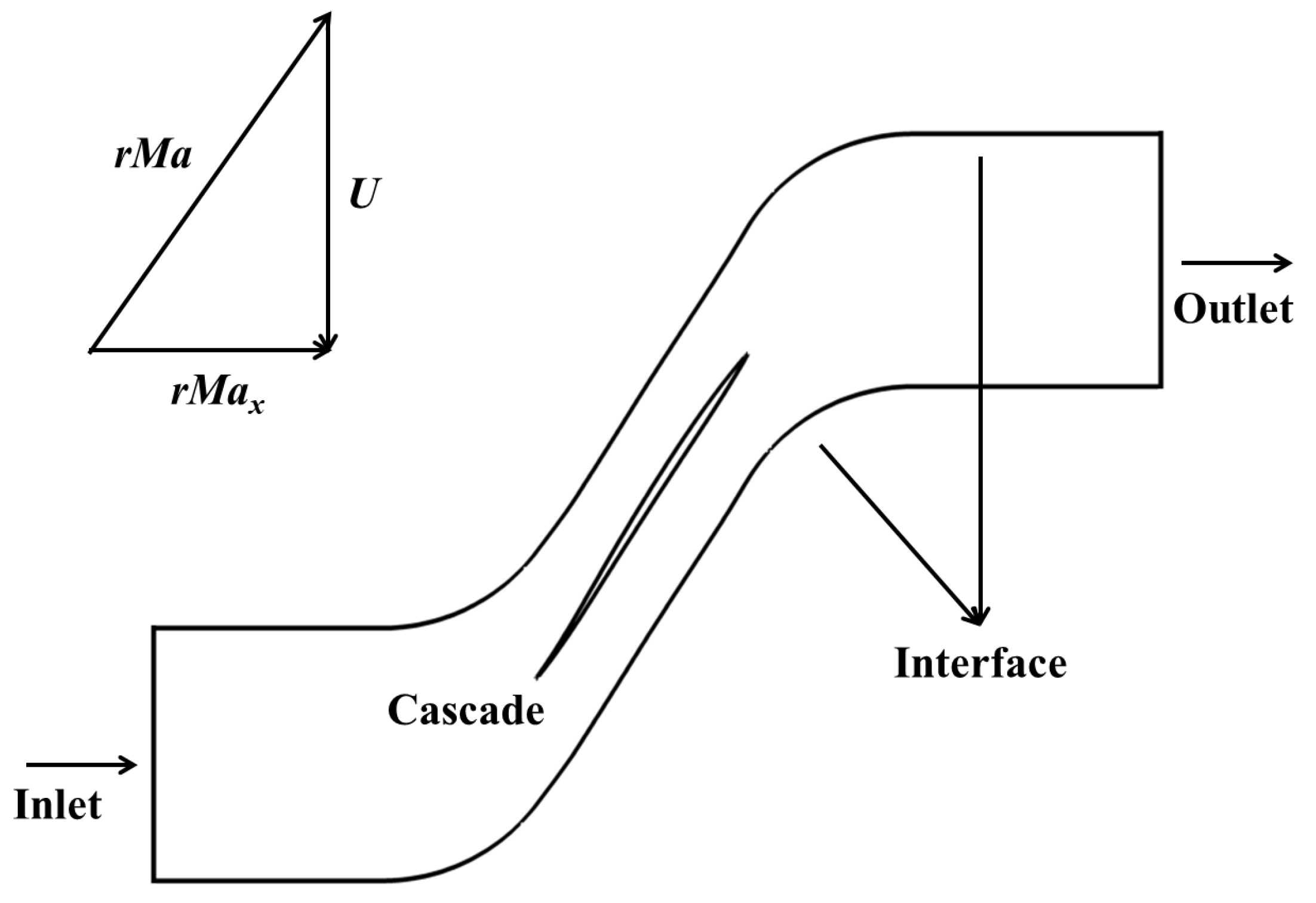
The commercial CFD solver ANSYS FLUENT 2020 R2 was employed to predict the flow field within the cascade passage. Geometry generation and meshing for the linear cascade were performed using ICEM CFD 2020 R2 within the ANSYS environment, with the resulting mesh subsequently imported into ANSYS FLUENT 2020 R2 for flow solution. Boundary conditions applied to the supersonic cascade computational domain are illustrated in Figure 1. Leveraging the unique incidence characteristic inherent to supersonic cascades, the simulation framework operates within an absolute coordinate system. This approach enables precise attainment of the target inlet flow angle and relative Mach number by adjusting the cascade translation velocity. Compared to a relative coordinate system formulation, the absolute reference frame offers distinct advantages for directly extracting key aerodynamic performance metrics—including total pressure ratio and adiabatic efficiency—parameters that would otherwise require additional transformation steps when computed in a rotating frame.
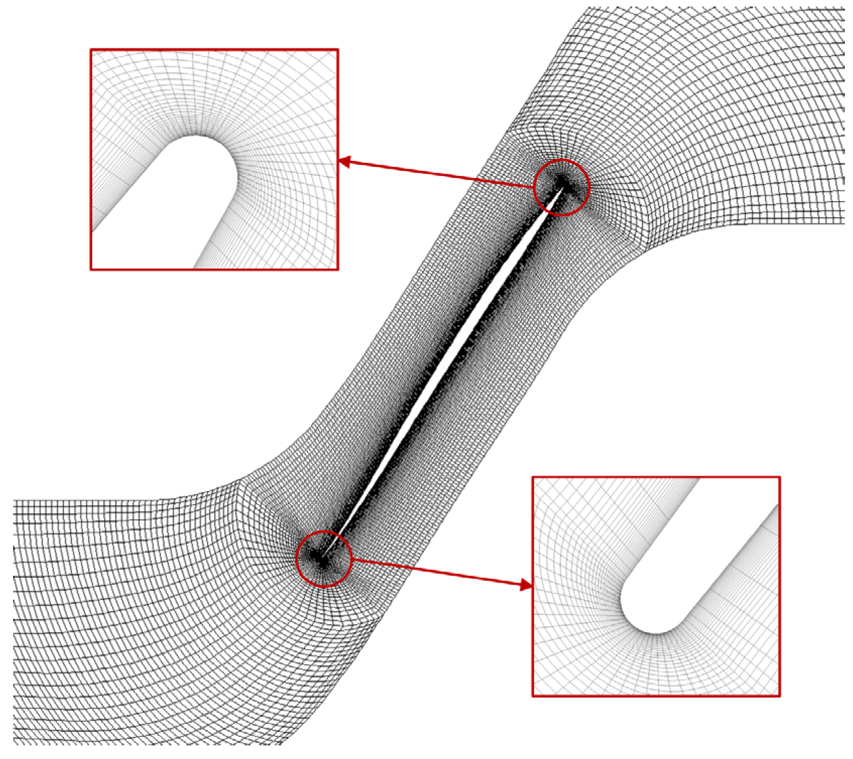
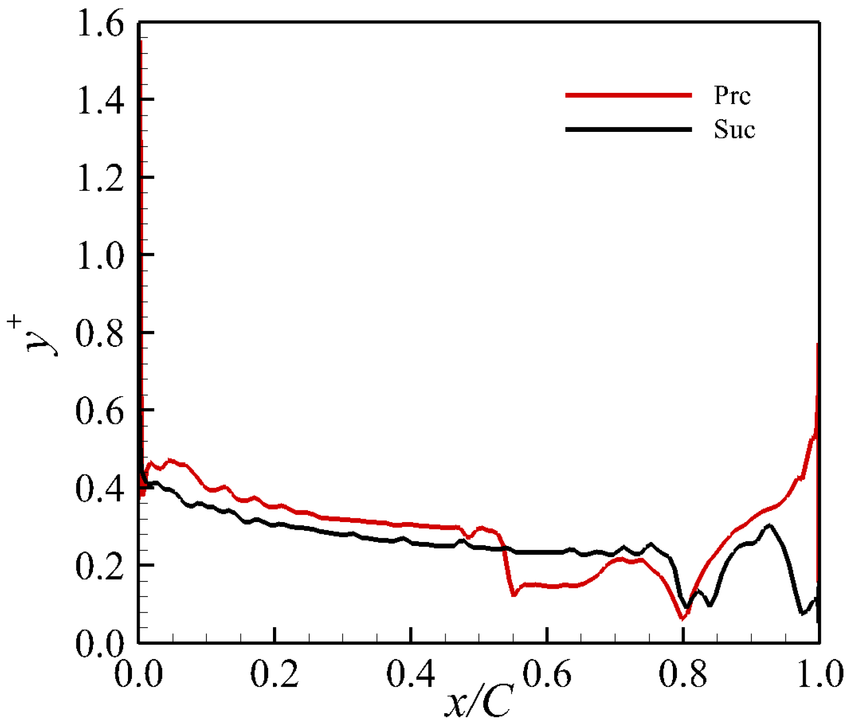
For the numerical validation case, the cascade passage was discretized using a structured mesh, the detailed topology of which is shown in Figure 2. The first grid layer adjacent to the blade surfaces maintains a thickness of 0.001 mm, ensuring that the y+ values across most surface regions remain approximately 0.4. This satisfies the near-wall resolution requirements for the SST turbulence model, with the surface y+ distribution illustrated in Figure 3. For the numerical solution, a density-based solver was employed. The inlet boundary was specified with an absolute total pressure of 101,325 Pa, an absolute total temperature of 300 K, and an axial inflow direction. Translational periodicity was applied to the lateral boundaries, while the blade surfaces were modeled as adiabatic no-slip walls. The solution was considered converged when the residual targets reached 1 × 10⁻⁴. The supersonic cascade’s performance characteristics were mapped by systematically varying the exit backpressure. To eliminate the influence of grid density on aerodynamic performance predictions, a grid independence study was conducted for the ARL-SL19 cascade; the results are presented in Table 2. The data demonstrate that once the mesh count exceeds 200,000 cells, the cascade’s total pressure ratio and total pressure loss coefficient exhibit negligible variation. Consequently, considering factors such as solution accuracy, computational resources, and simulation time, a mesh size of 200,000 cells was selected for subsequent investigations. The formulas for total pressure ratio and total pressure loss coefficient used in this study are given as follows:
Total pressure ratio:
π * = P 2 * P *
Total pressure loss coefficient:
ω = P w * P 2 w * P w * P w
Figure 2. Grid of the cascade passage.
Aerospace 13 00248 g002
Figure 3. The y+ distribution of the airfoil.
Aerospace 13 00248 g003
Table 2. Grid independence study.
CaseTotal Grid Cell Numberωπ*
174,2260.14481.752
2146,8940.14541.756
3204,1680.14601.761
4294,7120.14601.762
5389,2640.14611.762
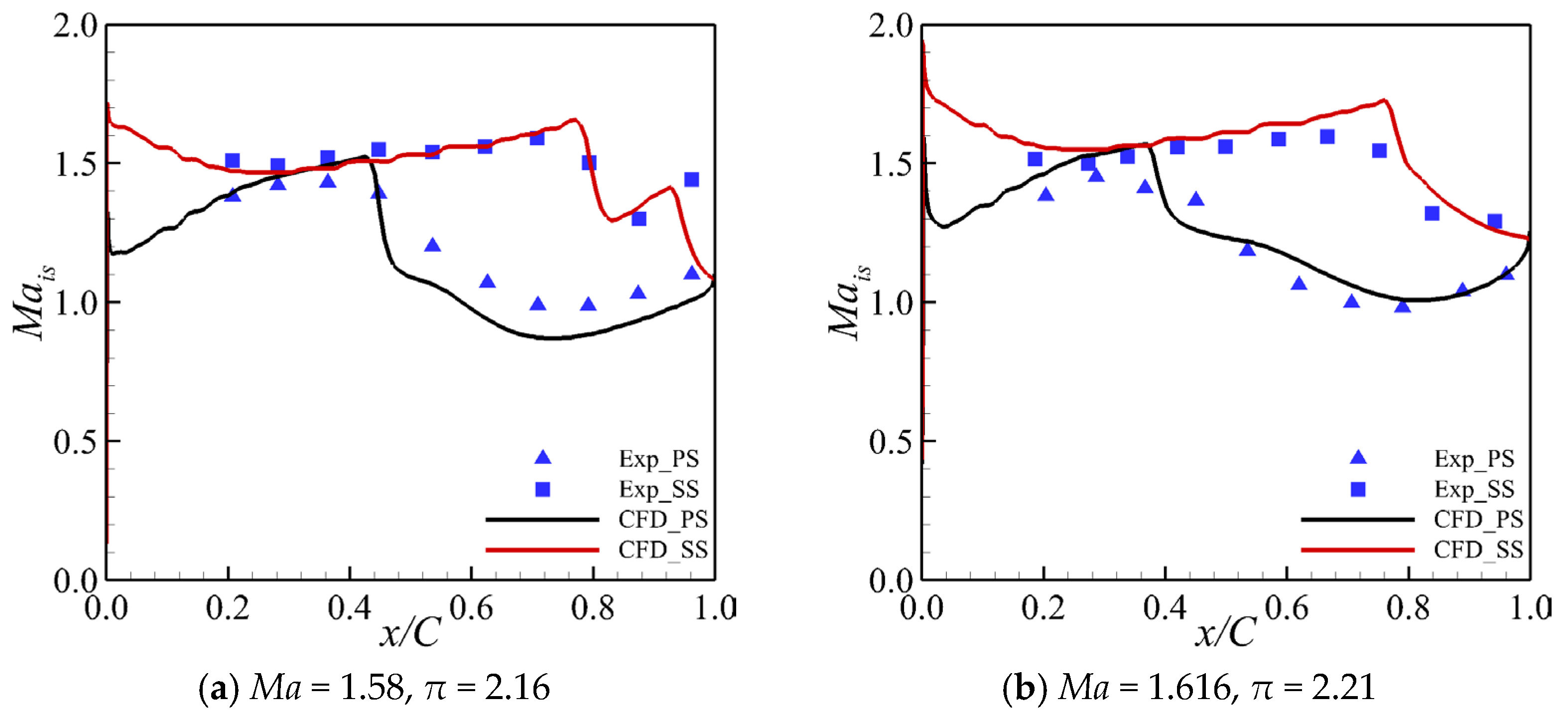
Numerical validation results for the ARL-SL19 cascade are presented in Figure 4, which compares CFD-predicted surface isentropic Mach number distributions against experimental data at inlet relative Mach numbers of 1.616 and 1.58. The experimental data were sourced from References [31,32,33]. The isentropic Mach number is defined by the following expression:
M a i s   =   P w * P γ 1 γ 1 2 γ 1
The results indicate that, despite certain discrepancies, the CFD simulation results show reasonable agreement with the experimental data. The numerical predictions successfully capture the overall trend of the surface isentropic Mach number distribution, with a mean absolute error of 5.11%. This comparison validates the reliability of the adopted numerical methodology. Consequently, to ensure solution accuracy and consistency, all subsequent numerical investigations in this study employed the identical mesh discretization strategy and numerical solution procedures detailed above.
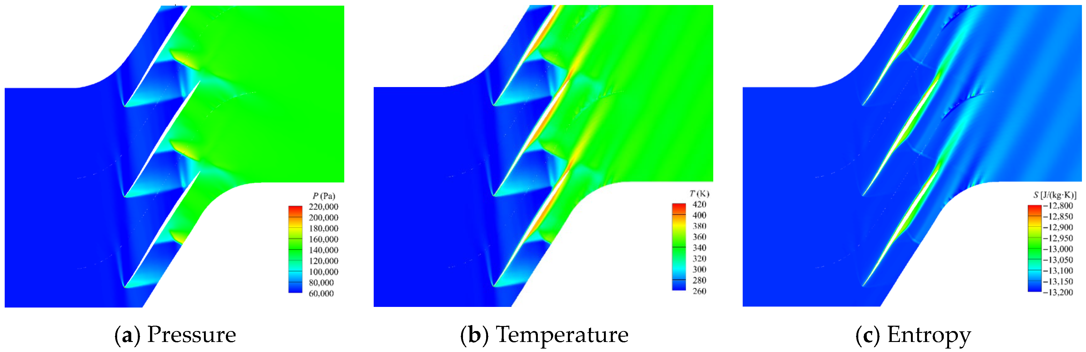
Figure 5 illustrates the internal passage flow field structure of the ARL-SL19 supersonic cascade at a relative inlet Mach number of 1.616 and a static pressure ratio of 2.21. The results reveal that significant boundary layer separation occurs on both the suction and pressure surfaces due to the interaction between the shock wave and the boundary layer. This separation process, combined with viscous dissipation, generates substantial entropy, resulting in a marked increase in gas temperature and significant flow losses. Therefore, the present study seeks to improve the internal flow structure of the ARL-SL19 supersonic cascade passage and reduce associated losses from shock–boundary layer interaction. This is achieved by proposing a parametric and aerodynamic optimization approach for supersonic profiles, which will be utilized to redesign and optimize the ARL-SL19 supersonic cascade for enhanced aerodynamic performance.

3. Supersonic Compressor Cascade Design Method

3.1. Geometric Relationship Between Unique Incidence and Cascade

Levine [14] developed a unique incidence calculation method for supersonic cascades. In the 1970s, Lichtfuss [15] summarized this calculation method and called it Levine’s method, which is of great importance in cascade parameterization. This paper will study the cascade parameterization method based on Levine’s method.
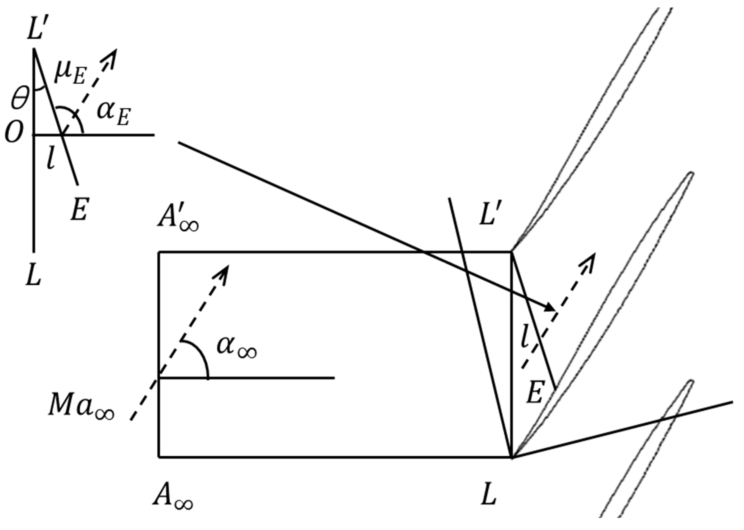
As shown in Figure 6, let L’E be the limit characteristic line whose length is lE and which intersects the suction surface of the cascade at point E. Point A and point A are two points at infinity of the frontal line L’L, and the flow on the line AA is homogeneous. The distance AA is equal to the cascade pitch t. Take A-A-L-E-L as the control body; due to the flow having a periodicity, the flow on AL is the same as the flow on AL. On AA, the aerodynamic parameters are inlet relative Mach number Ma, total pressure P*, and inlet flow angle α. On the boundary line L’E, the aerodynamic parameters are relative Mach number MaE, Mach angle μE, total pressure P*E, and flow inlet angle α. Assuming that the flow state is adiabatic and steady flow, and that the gas is non-viscous, the continuity equation is as follows:
K P * T * q ( M a ) t cos α = K P E * T * q ( M a E ) l E sin μ E
In Equation (4), q(Ma) is the flow function, K is a constant, and T* is the total temperature of the inlet flow. Assuming that the flow process is an isentropic flow, according to M a sin μ = 1 , Equation (4) can be transformed into
q ( M a ) cos α = q ( M a E ) l E t M a E
In Equation (5), the pitch t is a known quantity, and lE and MaE are geometrically related. The inlet relative Mach number Ma and the inlet flow angle α are unknown quantities. The angular relationship can be obtained from Equation (6):
tan θ = x E t y E
θ + π 2 = α E + μ E
The absence of an established relationship between point E coordinates and inflow relative Mach number necessitates supplementary conditions to solve for the unique inlet flow angle. Given the relatively weak leading-edge shock in the cascade, the inlet flow regime is approximated via simple wave relations. This enables the formulation of a coupled system of equations:
α E + ν M a E   =   α + ν M a
where ν(Ma) is the Pratt–Meyer function.
For a specified point E with prescribed airfoil geometry and cascade pitch t, the inflow relative Mach number Ma and unique inlet flow angle α are solvable numerically. Similarly, during design with known inflow relative Mach number, flow angle, and pitch t, neglecting leading-edge shock losses, the geometric parameter lE/t is determined, enabling solution of the limiting characteristic flow angle αE via Equation (5). Critically, fixed lE/t establishes a one-to-one correspondence between MaE, αE, and Ma, α. As established in Figure 6, determining lE, μE, and αE yields unique solutions for Point E coordinates and tangent direction at E, which are expressed as follows:
x E = l E sin μ E + α E π 2 y E = t l E cos μ E + α E π 2 d y d x x = x E = tan α E
It is worth noting that the aforementioned approach, which treats the fluid as inviscid, enables the rapid screening of supersonic cascades, thereby providing a well-established initial design for the supersonic blade profile.

3.2. Cascade Parameterization and Construction Methods

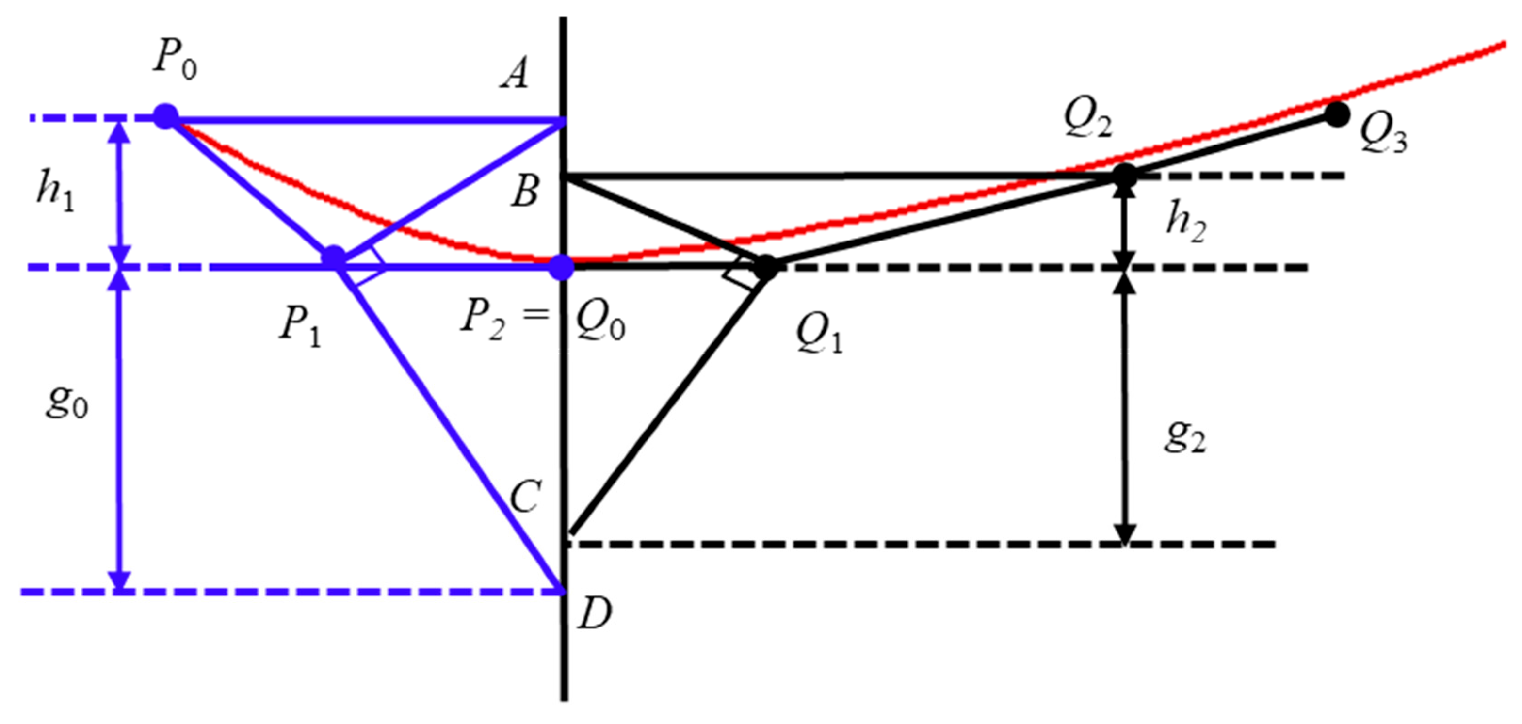
The preceding analysis indicates a strong dependency of the supersonic cascade’s inlet flow angle on the suction surface profile. To ensure that the inlet flow angle and Mach number conform to the prescribed design parameters, an airfoil design methodology is adopted. This method involves defining the suction surface first and then superimposing a thickness distribution to form the complete profile. A critical geometric constraint is that the suction surface must pass through point E, which represents its intersection with the limit characteristic line. For the airfoil parameterization, the suction surface is constructed using Bezier curves to guarantee profile smoothness. Specifically, the surface is divided into three segments, each defined by a distinct Bezier curve. The demarcation points between these adjacent segments are located at point E (the intersection with the limit characteristic line) and the point of maximum thickness (MT). As shown in Figure 7, a specific joining method is employed to ensure that the constructed suction surface satisfies G2 (curvature) continuity across these junctions.
Assume that when two Bezier curves are spliced, the vectors are ai = PiPi−1 and bj = QjQj−1, and the control points are Pi (i = 0, 1,…, n) and Qj (j = 0, 1,…, m). The sufficient condition for G0 continuity to be satisfied at the joining point is Pn = Q0. In order to satisfy G1 continuity, it is not sufficient to achieve G0 continuity; the curve normals at the connection points must also be in the same direction. This is expressed by the condition P(2) = αQ(0), where α > 0. This implies that the points Pn−1, Pn = Q0, and Q1 are collinear and in order.
To satisfy G2 continuity, two curves must not only meet the conditions for G0 (positional) and G1 (tangential) continuity at their junction but also exhibit continuous curvature. For spatial curves, this further implies that their osculating planes are coincident and their binormal vectors are co-directional at the point of connection. Figure 7 illustrates the joining scheme for the Bezier curves that form the suction surface. According to the endpoint properties of Bezier curves, the curvatures at the junction points, P(2) and Q(0), are given by
K P ( 2 ) = n 2 ( n 1 ) a 1 × a 2 n a 2 3 = ( n 1 ) a 1 × a 2 n a 2 3
K Q ( 0 ) = m 2 ( m 1 ) b 1 × b 2 m b 1 3 = ( m 1 ) b 1 × b 2 m b 1 3
Let the angle between vectors a1 and a2 be θ, the angle between b1 and b2 be φ, and h1 and h2 be the distances from P0 and Q2 to the common tangent, respectively. At this point, there are
a 1 × a 2 = a 1 a 2 sin θ = a 1 a 2 h 1 a 1 = a 2 h 1
b 1 × b 2 = b 1 b 2 sin φ = b 1 b 2 h 2 b 2 = b 1 h 2
The parallel lines of the common tangent through P0 and Q2 intersect the vertical line l through the point Q0 at points A and B, respectively, connect AP1 and BQ1, and make vertical lines through P1 and Q1 intersecting l at D and C. By the projective theorem, the length of a2 is the proportional midpoint of h1 and g1, i.e., a 2 2 = h 1 g 1 . Similarly, b 1 2 = h 2 g 2 . Equations (10) and (11) can be converted as follows:
K P ( 2 ) = ( n 1 ) a 1 × a 2 n a 2 3 = ( n 1 ) a 2 h 1 n a 2 3 = ( n 1 ) h 1 n h 1 g 1 = n 1 n g 1
K Q ( 0 ) = ( m 1 ) b 1 × b 2 m b 1 3 = ( n 1 ) b 1 h 2 n b 1 3 = ( n 1 ) h 2 n h 2 g 2 = m 1 m g 2
The curvature is continuous when K Q ( 0 ) = K P ( 2 ) , i.e.,
g 1 = m ( n 1 ) n ( m 1 ) g 2
To achieve identical curvature vectors at the connection point, three conditions must be satisfied: equal curvature magnitudes, a common osculating plane, and coplanar control points P0, P1, P2 = Q0, Q1, Q2 positioned on the same side of the common tangent line [34].
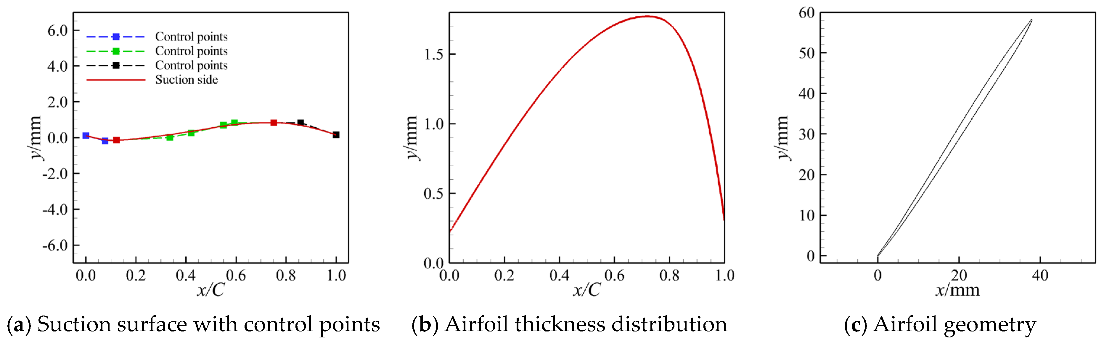
The designed supersonic cascade airfoil geometry is presented in Figure 8, where the suction surface profile in Figure 8a is constructed by joining three Bezier curve segments with junction points at the limiting characteristic intersection E and maximum thickness location MT; to enforce G2 continuity, the five control points adjacent to each junction reside on the identical side of the common tangent line, with the final airfoil geometry after thickness superposition shown in Figure 8c.

4. Aerodynamic Optimization Methodology and Applications for Supersonic Cascade

4.1. Parametric Aerodynamic Optimization Framework for Compressor Cascade

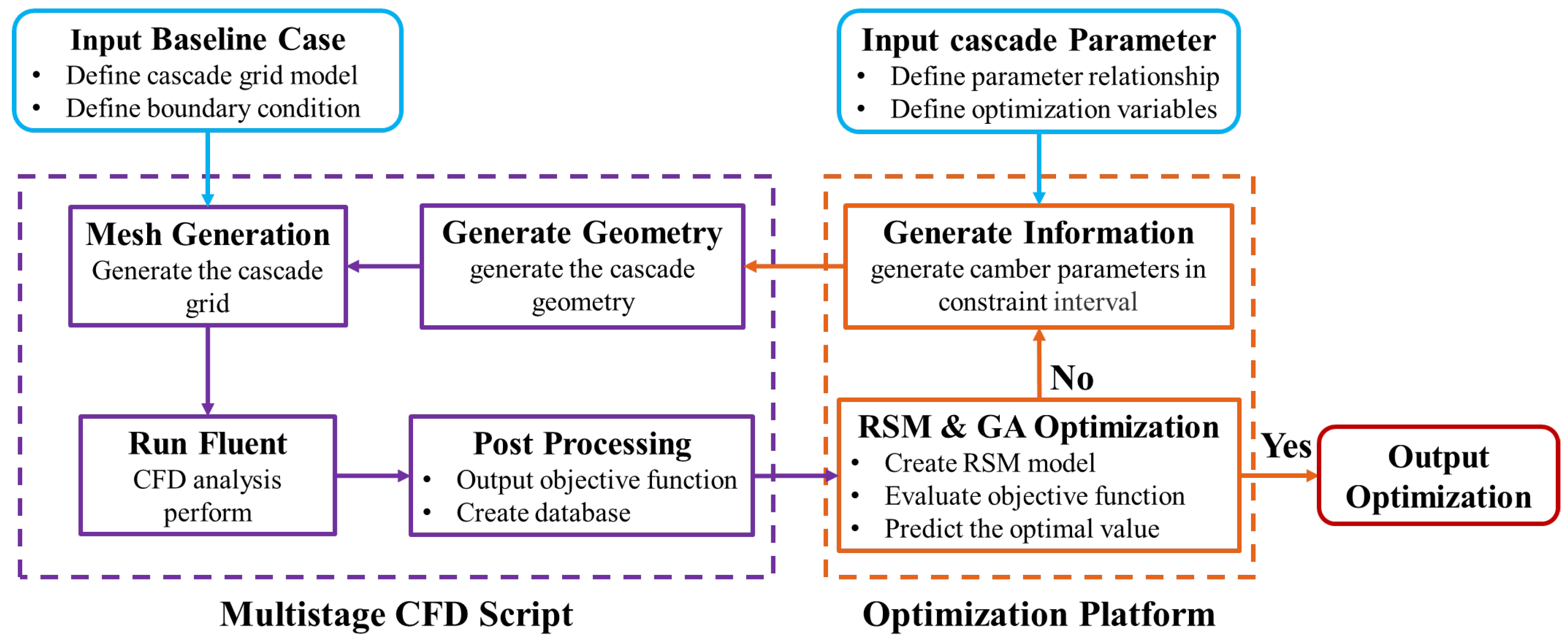
To streamline the aerodynamic optimization cycle and enhance the aerodynamic performance of supersonic cascades, this study establishes an integrated optimization platform utilizing a response surface methodology (RSM) coupled with a genetic algorithm. Response surface methodology is a comprehensive optimization technique integrating design of experiments (DoE) and mathematical modeling. Its core principle involves constructing a functional relationship between response variables and design variables (independent factors) through strategically selected local design points. This enables the systematic investigation of interaction effects among variables on target response values, thereby facilitating the optimization of these critical design parameters. The mathematical formulation is expressed as follows:
F X = a 0 + i = 1 N b i x i + i = 1 N c i x i 2 + i j i < j c i j x i x j
The genetic algorithm (GA) is a heuristic optimization technique inspired by the principles of natural selection and genetics in biological systems. It solves optimization problems by simulating biological evolution: Guided by individual fitness evaluation, it employs natural selection operations—reproduction, crossover, and mutation—to emulate genetic evolution, thereby progressively converging toward the optimal solution for the design variables. Owing to its robustness and computational efficiency, GA has gained widespread adoption across diverse engineering disciplines. This integrated aerodynamic optimization platform combines parametric modeling, design of experiments (DoE), mesh generation, numerical simulation, and multi-objective optimization. Modifying the parametric design variables enables comprehensive prediction and optimization of the supersonic cascade’s overall aerodynamic performance. The detailed optimization workflow is illustrated in Figure 9.
For the redesigned baseline supersonic cascade in this study, a parametric optimization model was developed using a modification-magnitude-based approach, focusing specifically on camber line modifications. The optimization procedure is implemented as follows:
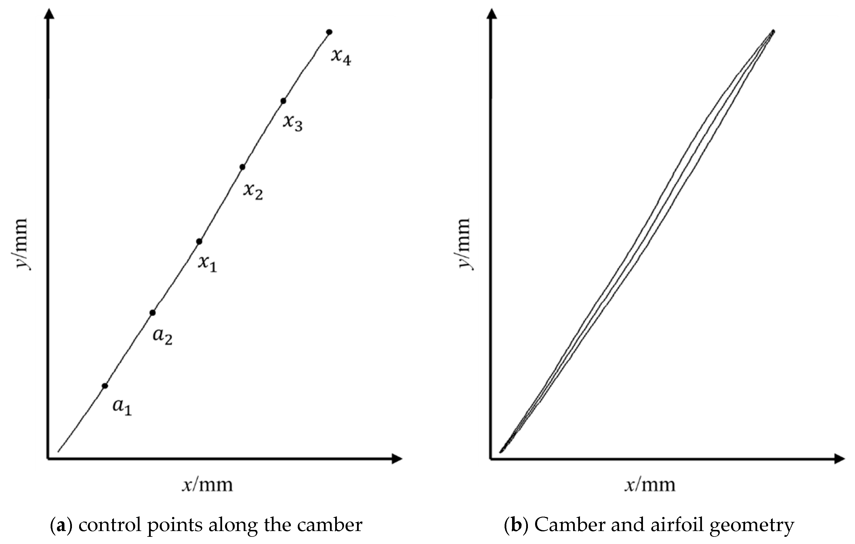
Design Variables: Six parametric control points (a1, a2, x1, x2, x3, x4) are defined along the chordwise direction of the camber line. Corresponding modification magnitudes (b1, b2, y1, y2, y3, y4) are assigned to each control point. The modified control points are then interpolated using a B-spline curve. The design variables x1 and x2 are control points near the cascade throat downstream of the limiting characteristic line, governing the pre-shock Mach number and shock strength. Positioned in the mid-to-rear passage, x3 lies within the primary diffusion region where shock–boundary layer interactions dominate. Its local curvature is critical for mitigating flow losses induced by such interactions. As the trailing-edge control point, x4 directly influences the wake structure and the associated total pressure loss in the downstream flow field. The resulting optimized supersonic airfoil camber line and geometric profile are illustrated in Figure 10.
Optimization Objective: Given that flow losses in supersonic cascades primarily originate from shock strength and shock wave–boundary layer interference, the total pressure loss coefficient was selected as the optimization objective function, with the camber line control point parameters serving as design variables. Furthermore, due to the unique incidence characteristic inherent to supersonic cascades, their aerodynamic performance exhibits high sensitivity to geometric alterations near the leading edge. Specifically, modifications to the suction surface profile upstream of the leading characteristic line can significantly perturb the inlet flow angle, causing the flow to fail to match the design inflow Mach number. Consequently, a geometric constraint was imposed during optimization: modifications were restricted to the rear four control points, while the modification magnitudes for the first two points (a1, a2) were fixed at zero. The functional relationship established for the total pressure loss coefficient is expressed as
ω ¯ min = F x 1 , x 2 , x 3 , x 4
The optimization process employed a genetic algorithm (GA) with the following configuration: a population size of 120, 200 evolution generations, a crossover probability of 0.9, and a mutation probability of 0.1. For the aerodynamic evaluation within the optimization loop, a set of 64 CFD sample points was generated. These design points were sampled based on uniform design theory, utilizing a parameter rotation strategy for the design variables (x1, x2, x3, x4). The results from these CFD evaluations were used to construct a second-order response surface model (RSM). To ensure the generalizability and accuracy of the surrogate model, its training was validated using the leave-one-out cross-validation method. Furthermore, an additional 8 randomly sampled points were used as an independent test set to assess the predictive capability of the final RSM.

4.2. Aerodynamic Characteristics and Flow Field Analysis of Supersonic Cascade

With a coefficient of determination (R2) of 0.92, an adjusted R2 of 0.90, and a root mean square error (RMSE) of 0.04%, the built RSM showed great prediction accuracy during the aerodynamic optimization process. Additionally, a Sobol global sensitivity analysis of the design factors was conducted; Table 3 summarizes the findings. According to the results, variable x3 is the most important control parameter since it accounts for 74.07% of the main effect and 84.39% of the total effect. Due to their interaction effects on the system response, variables x2 and x4 are of secondary importance, each contributing approximately 13% to the overall effect.
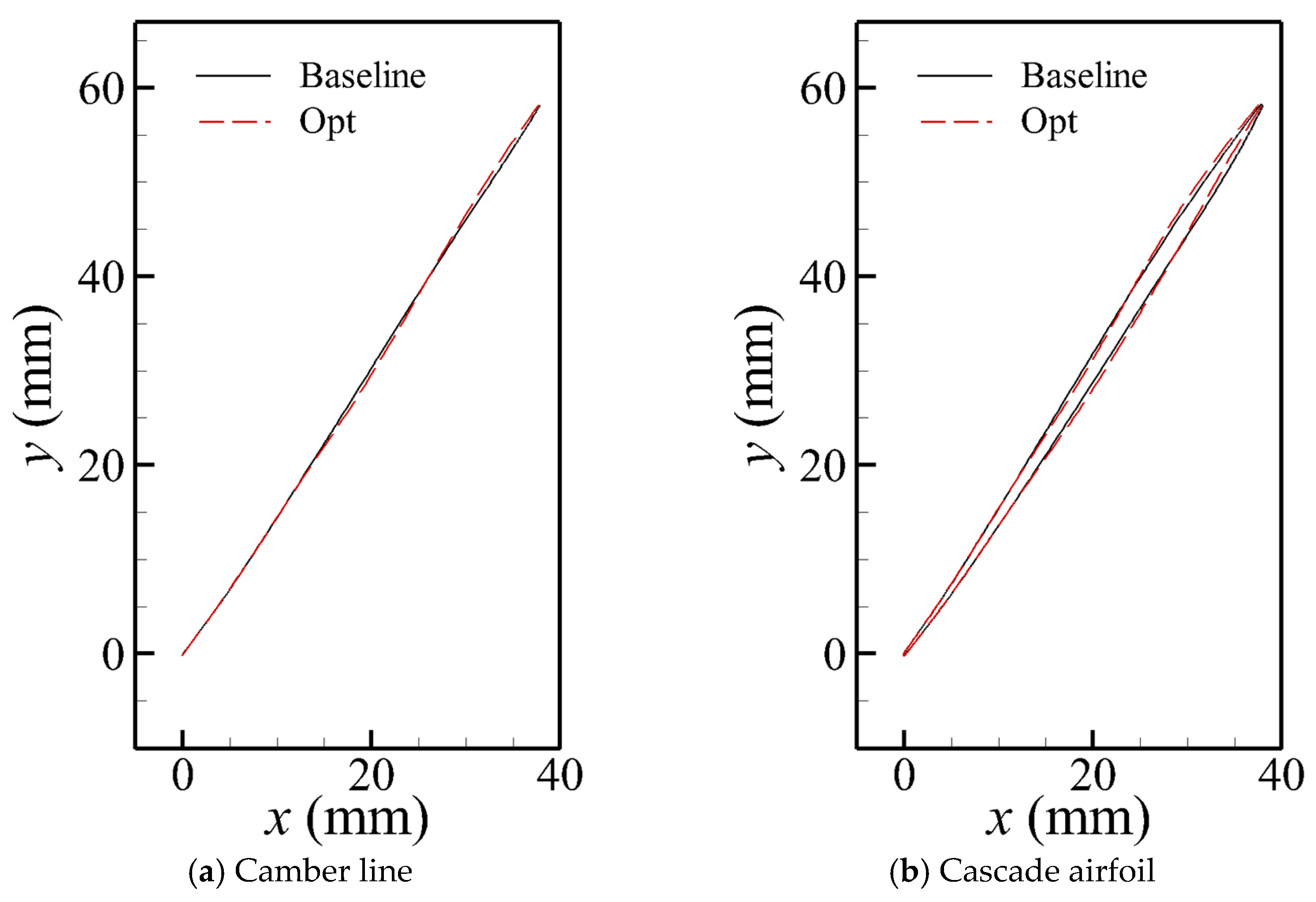
Figure 11 illustrates the changes in the camber line and geometry of the optimized cascade. Compared with the baseline, the mid-section camber of the optimized profile is slightly concave, resulting in a corresponding inward curvature of the constructed suction surface. This geometry can be utilized to generate an expansion fan, thereby attenuating the passage shock strength. Furthermore, the rearward shift of the throat location causes the normal shock to move downstream, extending the pressure-rise range of the cascade. The aft section of the cascade also becomes straighter, which helps reduce boundary layer separation behind the shock and thus mitigates flow loss.
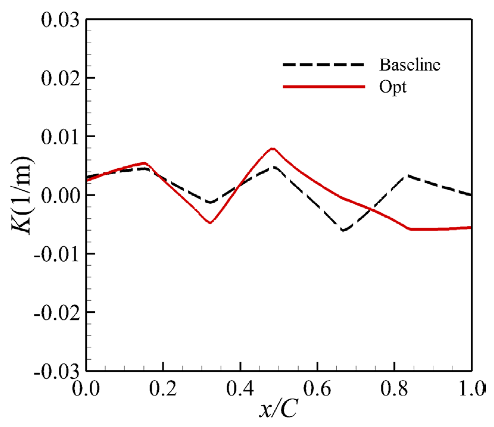
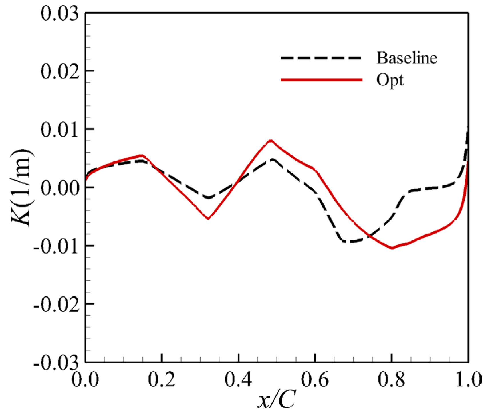
Curvature distribution comparisons between baseline and optimized airfoils are presented in Figure 12 and Figure 13. The formula used to calculate the curvature distribution in the figures is given below.
K ( u ) = C u × C u C u 3
where C(u) is the B-spline function representing the profile curve. The first derivative C′(u) is
C u = i = 0 n 1 N i , p 1 u P i 1
Similarly, the second derivative C″(u) is
C u = i = 0 n 2 N i , p 2 u P i 2
In these equations, Pi denotes the control points of the B-spline, and p represents the degree of the B-spline function.
Figure 12 depicts suction surface curvature evolution, revealing an enhanced curvature variation amplitude in the mid-chord region of the optimized profile. Notably, the aft suction surface undergoes curvature sign reversal from positive to negative. As shown in Figure 13, the optimized camber line exhibits intensified curvature modulation mid-chord while developing a reduced gradient in the rear section. This strategic curvature manipulation enables two critical flow control mechanisms: fore-section curvature governs passage shock strength, while minimized aft-curvature variation stabilizes post-shock boundary layer development—collectively achieving the aerodynamic optimization objective of efficient diffusion.
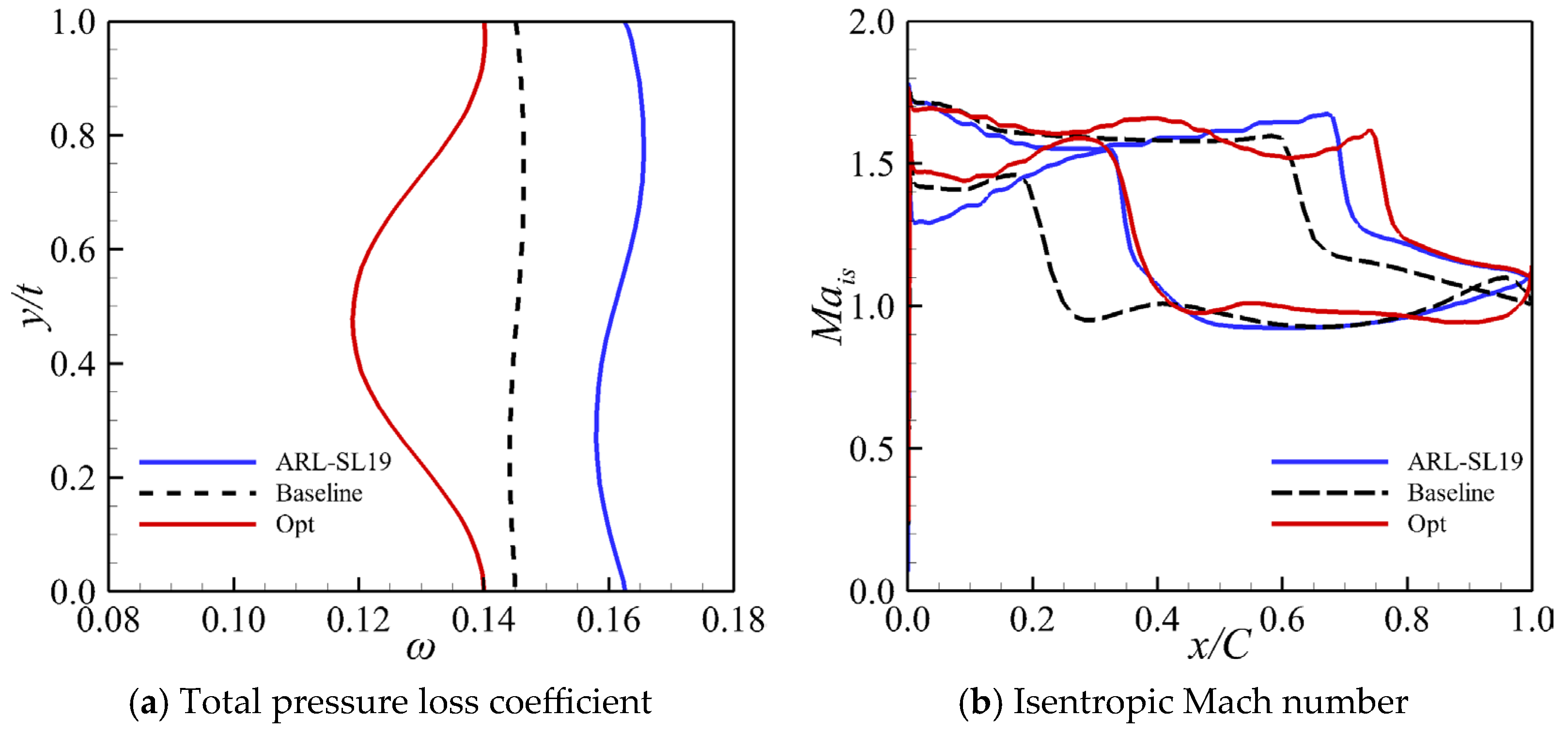
Table 4 presents a comparative analysis of the aerodynamic performance at the design point following the aerodynamic redesign and optimization of the ARL-SL19 cascade. This condition is characterized by an incoming flow with a relative Mach number of 1.616 and a back pressure of 155,000 Pa. The results indicate a significant improvement in the total pressure loss coefficient for the redesigned prototype cascade compared to the baseline ARL-SL19, with a reduction of 11.78%. Subsequent aerodynamic optimization yielded further enhancements, resulting in a total pressure loss coefficient reduction of 21.25% relative to the ARL-SL19 cascade and 10.74% relative to the redesigned prototype. To further elucidate the variations in aerodynamic performance following redesign and optimization, Figure 14a illustrates the pitch-wise distribution of the total pressure loss coefficient. These data reveal that the redesigned cascade exhibits a lower and more uniform loss profile. This suggests a mitigation of flow separation induced by shock wave–boundary layer interaction, as well as a reduction in shock intensity. Following aerodynamic optimization, the total pressure loss coefficient within the passage is significantly reduced—attributed to the further suppression of flow separation and shock strength—thereby substantially improving the flow field within the supersonic cascade passage. Figure 14b depicts the surface isentropic Mach number distribution. The results demonstrate that the shock position on the pressure surface of the optimized cascade is shifted further downstream (aft). This shift significantly attenuates the shock intensity within the cascade passage, correlating with the reduction in total pressure loss observed in Figure 14a. Furthermore, on the suction surface of the optimized cascade, the isentropic Mach number distribution downstream of the shock is smoother, indicating a more stable pressure recovery process.
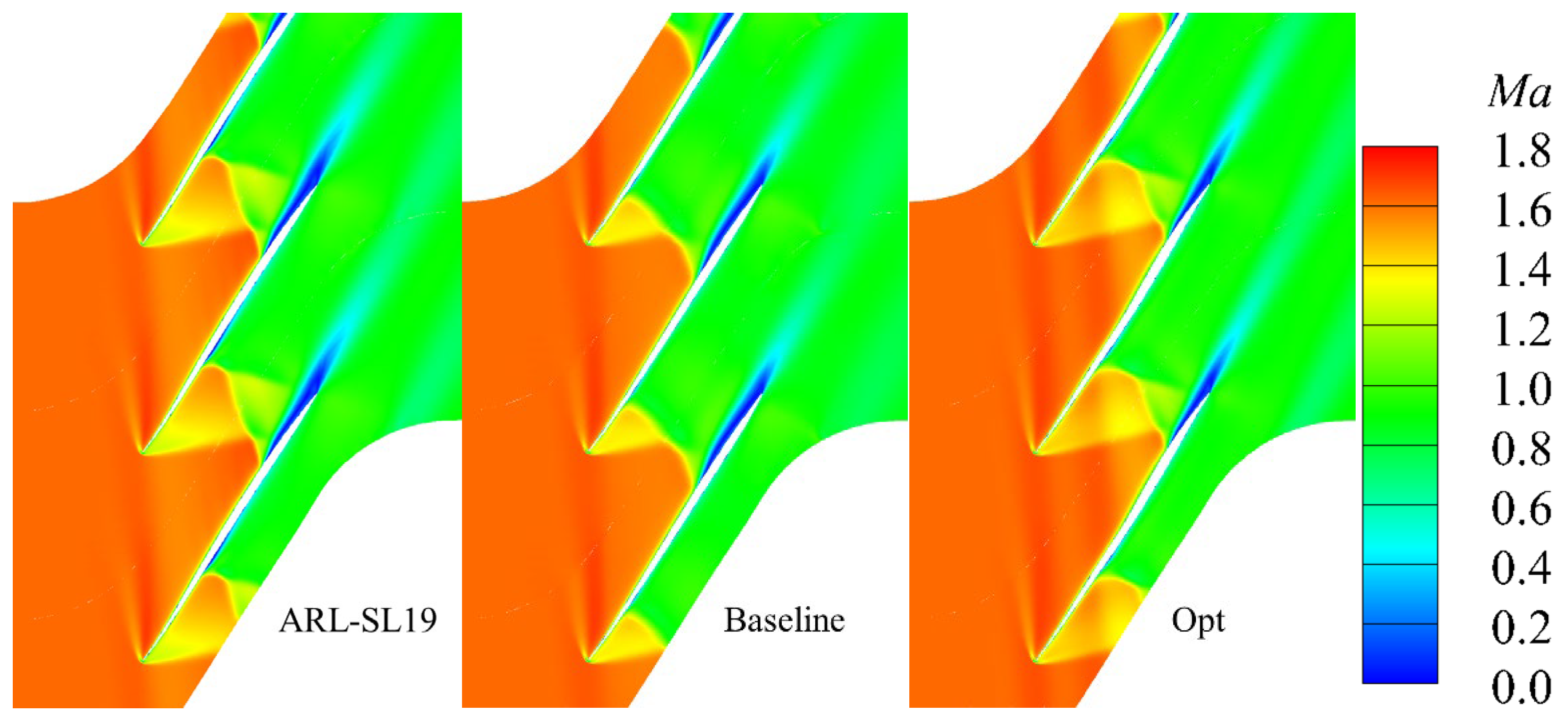
Figure 15 compares the passage flow structures of the cascades at design conditions. Relative to the ARL-SL19 cascade, the baseline cascade demonstrates attenuated boundary layer separation and weakened shock wave–boundary layer interaction, resulting in lower total pressure losses. The ARL-SL19 compression system comprises two oblique shocks followed by a terminal normal shock, whereas the baseline cascade employs a single oblique shock transitioning to a normal shock—albeit with marginally forward-shocked shock positioning. Concurrently, the baseline cascade exhibits enhanced geometric conformity on the pressure surface. The mid-chord boundary layer separation induced by shock interference shows significantly less prominence compared to the pronounced separation observed on the ARL-SL19 pressure surface. Following aerodynamic optimization, the terminal normal shock migrates rearward in the optimized cascade passage. This spatial shift reduces the separation zone extent on the suction surface while diminishing the overall passage shock intensity. The rearward shock position further enables a higher total pressure ratio relative to the baseline cascade.
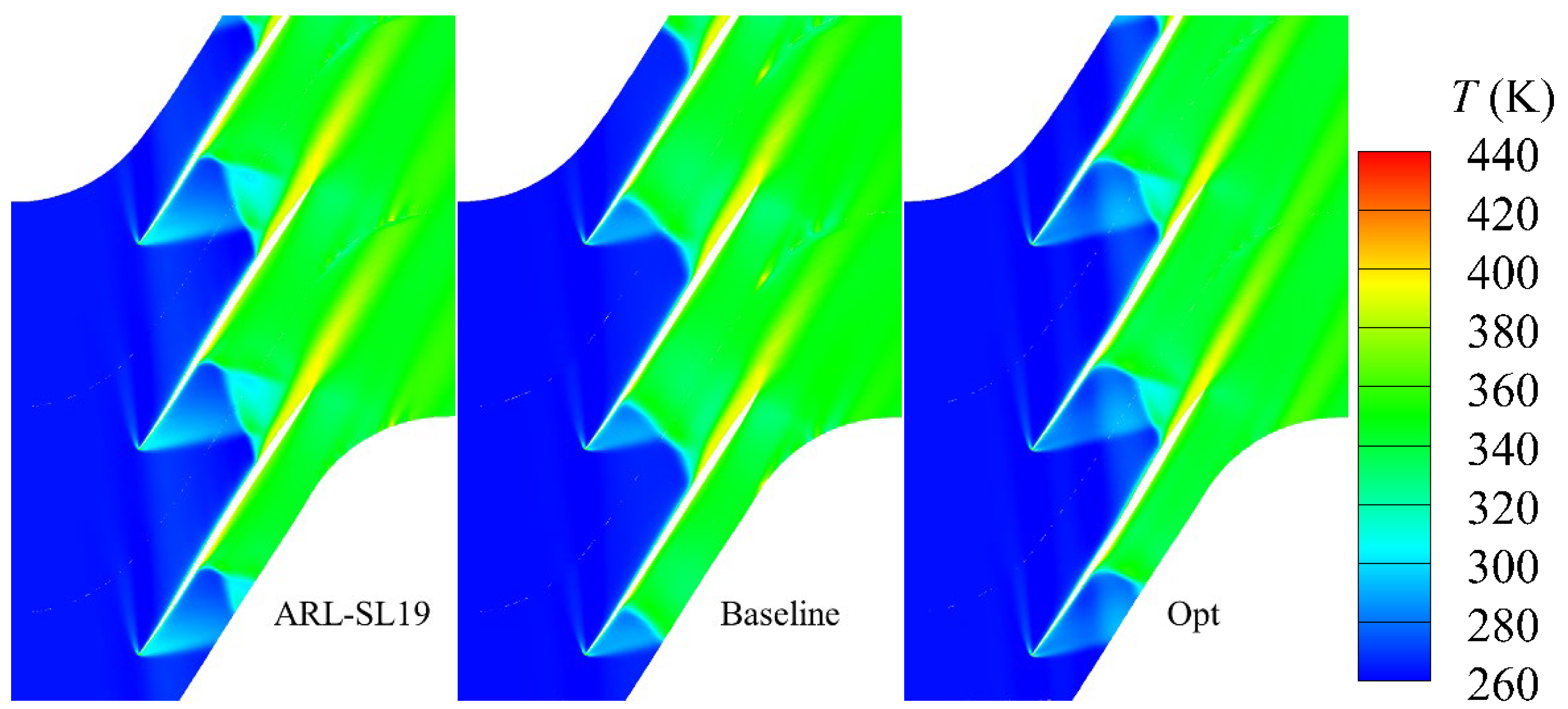
Temperature distributions within cascade passages at design conditions are compared in Figure 16. Analysis confirms significant temperature elevation through shock structures where abrupt pressure rise and flow deceleration occur. Concurrently, viscous dissipation—the irreversible conversion of mechanical energy to internal energy via viscous shear—elevates fluid temperatures within dissipation zones. This thermal signature manifests as pronounced temperature gradients in suction surface separation regions, exceeding core flow temperatures by measurable margins. The ARL-SL19 cascade exhibits the most severe flow separation, consequently developing the most extensive high-temperature footprint. Post-optimization, attenuated shock intensity and mitigated shock wave–boundary layer interaction significantly suppress flow separation near the suction surface trailing edge. This aerodynamic refinement correspondingly reduces the spatial domain affected by viscous dissipation heating.
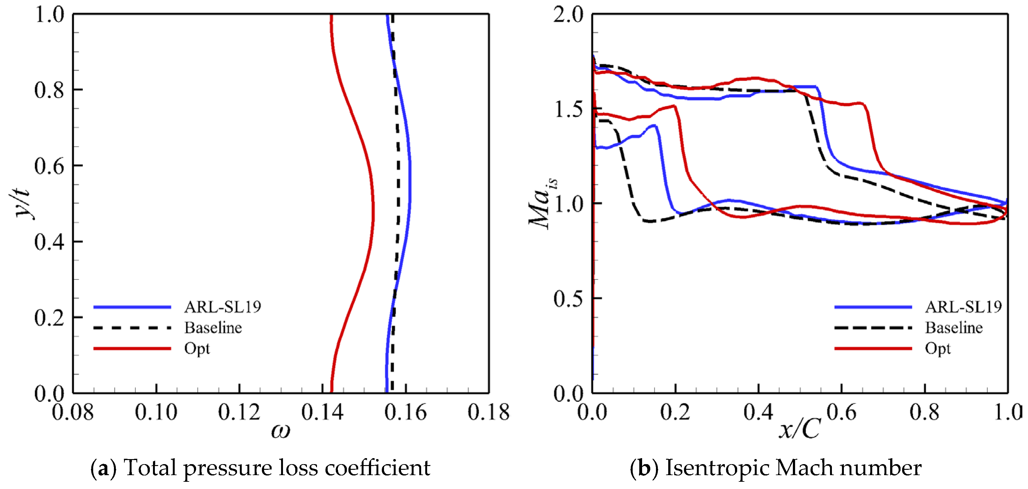
Aerodynamic performance comparisons under near-stall conditions are presented in Table 5. Under near-stall conditions, the incoming flow has a relative Mach number of 1.616, with corresponding back pressures of 170,000 Pa for the ARL-SL19 cascade, 165,000 Pa for the baseline cascade, and 173,000 Pa for the optimized cascade. Data analysis reveals that the baseline cascade achieves a lower total pressure loss coefficient relative to ARL-SL19, albeit with a moderate reduction in total pressure ratio. Following aerodynamic optimization, the optimized cascade exhibits an increase in total pressure ratio by 2.05% compared to the ARL-SL19 cascade. This enhancement in pressure rise contributes to a widened operating range. Concurrently, a significant reduction in the total pressure loss coefficient is achieved—9.20% lower than the ARL-SL19 cascade and 6.66% lower than the redesigned baseline cascade. Figure 17 illustrates the pitch-wise distributions of the total pressure loss coefficient and the surface isentropic Mach number, confirming that the optimized cascade significantly attenuates passage shock intensity and wake losses while shifting the shock rearward. This flow modification yields a marked reduction in core flow region losses and further improves pressure rise capability.
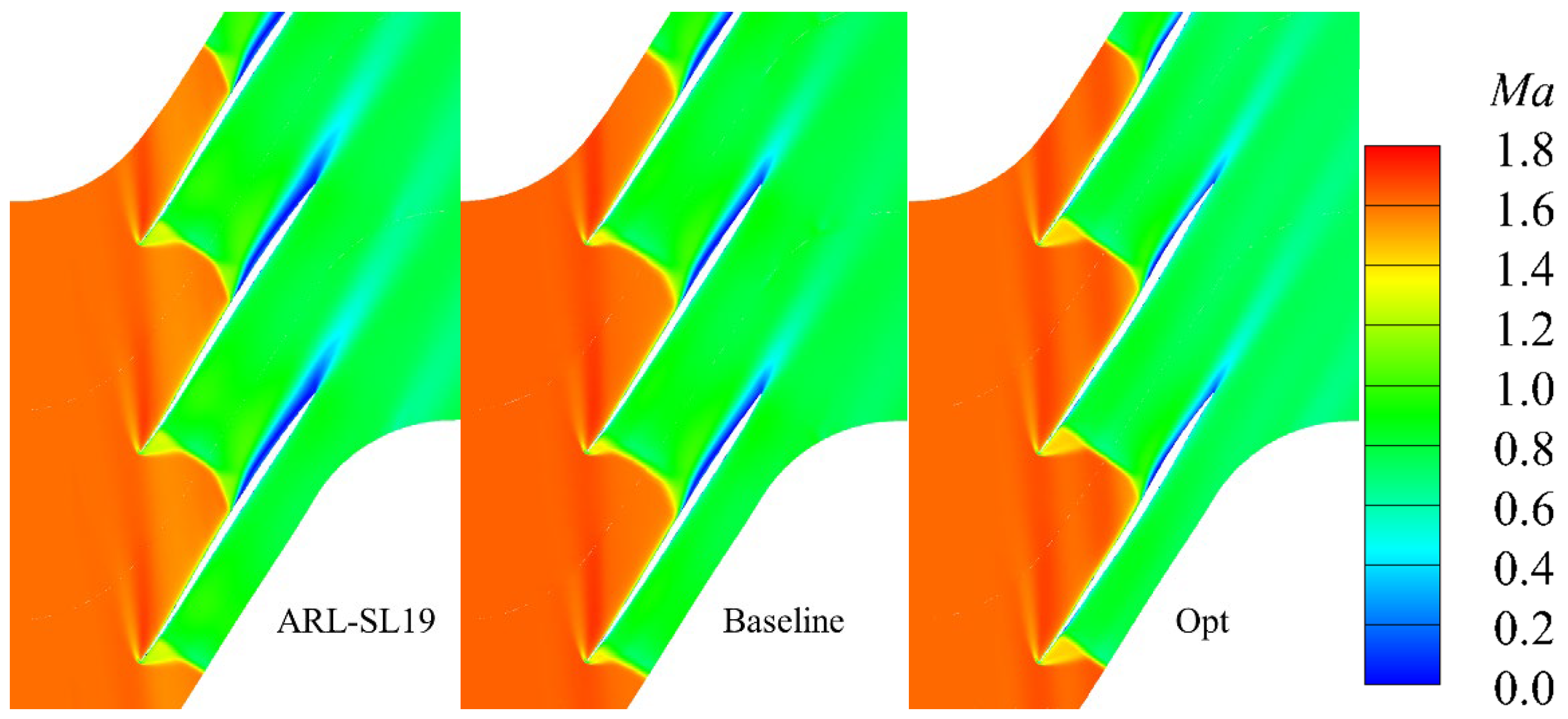
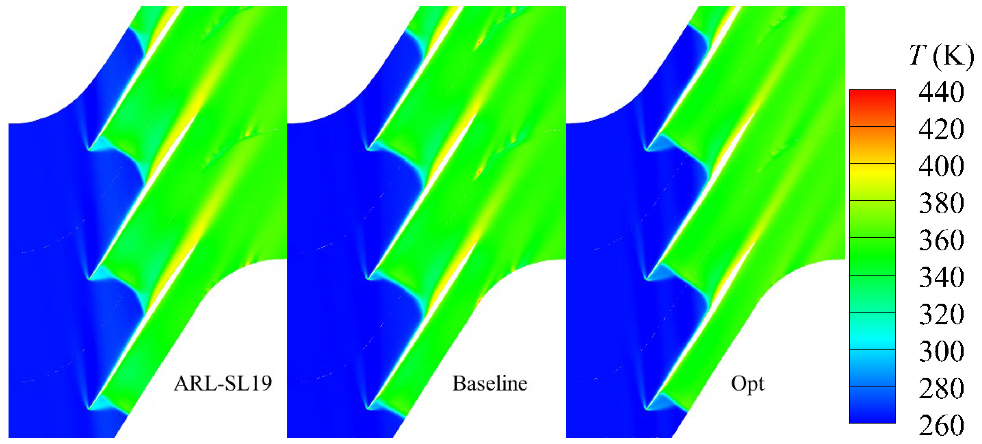
Figure 18 presents relative Mach number distributions under near-stall conditions, revealing significantly reduced low-momentum zones on the baseline cascade’s suction surface compared with the ARL-SL19. This indicates attenuated shock wave/boundary-layer interaction and suppressed flow separation. Post-optimization, separation phenomena—particularly near the trailing edge—are further mitigated, substantially shrinking low-velocity regions and enhancing passage throughflow capability for efficient diffusion. Figure 19 displays static temperature distributions under identical conditions; as established, viscous dissipation elevates temperatures in separation zones. Optimization-induced suppression of shock wave–boundary layer interaction markedly reduces suction surface separation areas, consequently minimizing thermal footprints and associated flow losses.
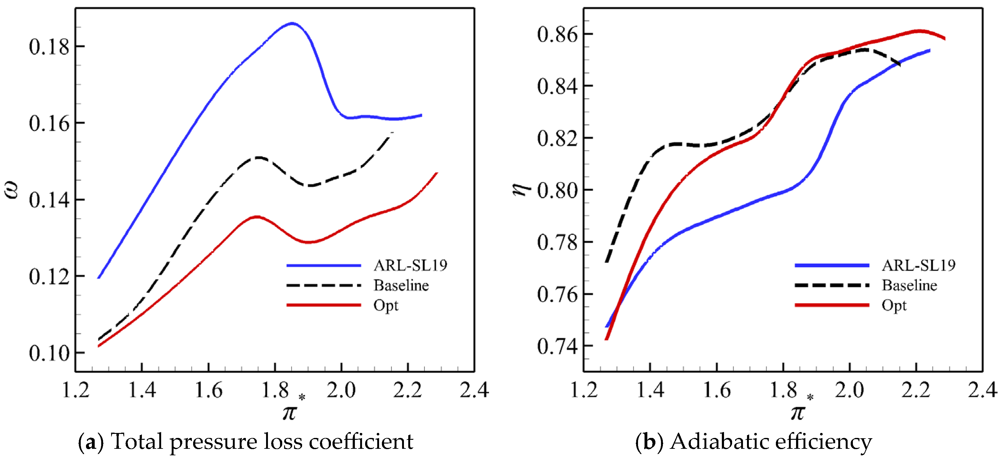
To comprehensively demonstrate the overall performance improvement achieved through the aerodynamic redesign and optimization of the ARL-SL19 cascade, Figure 20 presents a comparison of performance curves for each cascade. According to the data in Figure 20a, compared with the ARL-SL19 cascade, the total pressure loss coefficient of the baseline cascade is significantly reduced across the entire operating range. After optimization, the optimized cascade exhibits a further reduction in the total pressure loss coefficient compared to the baseline cascade. Since the optimization focused on enhancing aerodynamic performance at high-pressure ratios and extending the pressure ratio range, the reduction in total pressure loss coefficient is more pronounced under high-pressure-ratio conditions. Figure 20b shows the comparison of adiabatic efficiency among the cascades. The data indicate that the adiabatic efficiency of the baseline cascade at the design condition is 2.3% higher than that of the ARL-SL19 cascade, with noticeable improvements also achieved at off-design conditions. After optimization, the adiabatic efficiency of the optimized cascade is slightly lower than that of the baseline cascade at low pressure ratios but exceeds that of the baseline cascade when the total pressure ratio is greater than 1.8. Although the operating range of the baseline cascade was reduced compared to the ARL-SL19 cascade after redesign, the pressure rise range is broadened following aerodynamic optimization.
Based on the above research results, the aerodynamic performance of the baseline cascade is significantly improved compared to the ARL-SL19 cascade after aerodynamic redesign. During the aerodynamic optimization process, emphasis was placed on enhancing the aerodynamic performance of the cascade within the high-pressure-ratio range while maintaining its performance at low pressure ratios (as shown in Figure 20). It can be concluded that, without altering aerodynamic parameters, only minor modifications to the blade profile geometry can alter the shock intensity distribution within the cascade (as shown in Figure 15 and Figure 18). This leads to a reduction in shock losses, suppression of boundary layer separation near the trailing edge of the blade profile, broadening of the total pressure rise range, and overall improvement in cascade performance, thereby achieving efficient diffusion. It should be noted that, as this study is based on the design of a two-dimensional cascade, additional factors such as secondary flow losses (e.g., leakage vortices and passage vortices) and radial pressure gradients must be considered when applying the findings to the design and optimization of the tip section profile in a high-load counter-rotating compressor.

5. Conclusions

This study proposes an aerodynamic design methodology for supersonic airfoils based on an in-depth analysis of internal cascade flow physics. Leveraging genetic algorithms, second-order response surface models, and CFD simulations, an integrated aerodynamic optimization framework was established. Applied to the ARL-SL19 supersonic cascade, the key conclusions are as follows:
1. Bezier-based suction surface parameterization proves effective for generating aerodynamically superior initial profiles. The segmented curve construction ensures high-order continuity (G2) while preserving key aerodynamic parameters. Strategic geometric modifications significantly reduce passage flow losses without altering inflow conditions.
2. Utilizing the established aerodynamic optimization method for supersonic cascades, the optimized cascade achieved at the design condition reduces the total pressure loss coefficient by 10.74%. Under near-stall conditions, the total pressure loss coefficient is further decreased by 6.66%. In addition, the operating pressure-rise range of the supersonic cascade is effectively extended, with the maximum total pressure ratio increased by 6.32%. These improvements collectively result in a significant enhancement of the overall aerodynamic performance of the supersonic compressor cascade. The results indicate that, without altering the aerodynamic parameters of the cascade, modest geometric modifications to the cascade can effectively redistribute shock strength within the flow passage, mitigate boundary layer separation, and thus reduce aerodynamic losses.
3. The core issue in the design of a supersonic compressor cascade passage centers on controlling and utilizing shock waves while mitigating the extent and intensity of boundary layer separation. To this end, in the aerodynamic redesign and optimization of the ARL-SL19 supersonic cascade under the design inflow Mach number, the resulting low-loss diffusion blade profile exhibits the following geometric characteristics on the suction surface: the curvature of the forward segment governs the shock wave intensity, while the aft segment features a gradually varying negative curvature that facilitates boundary layer flow control, reduces shock wave–boundary layer interactions, and achieves efficient diffusion.

Author Contributions

Conceptualization, H.C.; methodology, H.C.; software, Z.L.; validation, Z.L. and Y.W.; resources, H.C.; data curation, Z.L. and Y.W.; writing—original draft preparation, Z.Z. and Z.L.; writing—review and editing, Z.Z. and Z.L.; visualization, Z.Z. and Y.W.; supervision, H.C.; project administration, H.C.; funding acquisition, Z.Z. and H.C. All authors have read and agreed to the published version of the manuscript.

Funding

This research was supported by the following grants: the State Key Program of Regional Innovation and Development Joint Fund National Natural Science Foundation of China (No. U24A20138); 2024 Key Research Fields Support Project of Shenzhen University of Information Technology (No. SZIIT2025KJ037); Shenzhen University of Information Technology Projects (No. TD2024E004); and the Scientific Research Platform and Projects of Colleges and Universities of Guangdong Province Department of Education (No. 2023ZDZX3082).

Data Availability Statement

The related data is available under reasonable request.

Conflicts of Interest

The authors declare no conflict of interest.

Nomenclature

KCurvature (1/m)
MaRelative Mach number
TTemperature
tPitch
thkThickness (mm)
PPressure (Pa)
PiControl points of the B-spline function
pDegree of the B-spline function
URim speed (r/min)
xCoordinate x (mm)
x/CRelative chord length
yCoordinate y (mm)
y/tRelative pitch length
αFlow inlet angle
ηAdiabatic efficiency
μMach angle
πStatic pressure ratio
π*Total pressure ratio
ωTotal pressure loss coefficient
γSpecific heat ratio
Subscripts/Superscripts
EIntersection point of line L’E and cascade suction side
xCoordinate x component
wRelative coordinate system conditions
*Stagnant conditions
isIsentropic conditions
Inlet condition
2Outlet condition

References

  1. Hamilton, N.; Cal, R.B. Anisotropy of the Reynolds stress tensor in the wakes of wind turbine arrays in Cartesian arrangements with counter-rotating rotors. Phys. Fluids 2015, 27, 015102. [Google Scholar] [CrossRef]
  2. Wang, L.; Mao, X.; Gao, L.; Guo, Y.; Yu, Y. Effect of axial slot casing treatment on the flow instability for different speed ratios in a counter-rotating axial flow compressor. Aerosp. Sci. Technol. 2023, 139, 108374. [Google Scholar] [CrossRef]
  3. Wang, M.; Li, Z.; Yang, C.; Zhao, S.; Zhang, Y.; Lu, X. Large eddy simulation of the separated flow transition on the suction surface of a high subsonic compressor airfoil. Phys. Fluids 2020, 32, 034110. [Google Scholar] [CrossRef]
  4. Luo, D.; Sun, X.; Huang, D. Design of 1+ 1/2 counter rotating centrifugal turbine and performance comparison with two-stage centrifugal turbine. Energy 2020, 211, 118628. [Google Scholar] [CrossRef]
  5. Sun, S.; Wang, S.; Zhang, L.; Ji, L. Design and performance analysis of a two-stage transonic low-reaction counter-rotating aspirated fan/compressor with inlet counter-swirl. Aerosp. Sci. Technol. 2021, 111, 106519. [Google Scholar] [CrossRef]
  6. Kantrowitz, A. The Supersonic Axial-Flow Compressor. 1946. Available online: https://scholar.google.com/scholar?hl=zh-CN&as_sdt=0%2C5&q=Kantrowitz%2C+A.+The+supersonic+axial-flow+compressor%5BR%5D.+1946.&btnG= (accessed on 5 March 2025).
  7. Tweedt, D.L.; Schreiber, H.A.; Starken, H. Experimental investigation of the performance of a supersonic compressor cascade. J. Turbomach. 1988, 110, 456–466. [Google Scholar] [CrossRef]
  8. Ninnemann, T.; Ng, W.F. Loss reduction using riblets on a supersonic through-flow fan blade cascade. J. Fluids Eng. 2004, 126, 642–649. [Google Scholar] [CrossRef]
  9. Sun, S.; Li, X.; Guo, M.; Song, J.; Yang, C.; Wang, J. Effect of inlet Mach number on performance and flow structure of an axial supersonic through-flow fan cascade. Phys. Fluids 2023, 35, 056104. [Google Scholar] [CrossRef]
  10. Chen, S.; Meng, Q.; Liu, Y.; Liu, H.; Wang, S. Unsteady numerical simulation in a supersonic compressor cascade with a strong shock wave. Int. J. Turbo Jet-Engines 2021, 38, 421–431. [Google Scholar]
  11. Wang, Z.; Song, T.; Chen, X.; Wang, M. Control on SWBLI by vortex generator in a supersonic cascade. Aerosp. Sci. Technol. 2024, 151, 109323. [Google Scholar] [CrossRef]
  12. Sun, X.; Yang, S.; Zhao, Q. Shock loss model and blade profile optimization design of a supersonic cascade. Proc. Inst. Mech. Eng. Part G J. Aerosp. Eng. 2015, 229, 1325–1329. [Google Scholar] [CrossRef]
  13. Rhee, J.; Im, J.; Kim, J.; Song, S.J. Humidity effects on the aerodynamic performance of a transonic compressor cascade. Int. J. Heat Mass Transf. 2019, 140, 743–751. [Google Scholar] [CrossRef]
  14. Levine, P. Two-dimensional inflow conditions for a supersonic compressor with curved blades. J. Appl. Mech. 1957, 24, 165–169. [Google Scholar] [CrossRef]
  15. Lichtfuss, H.J.; Starken, H. Supersonic cascade flow. Prog. Aerosp. Sci. 1974, 15, 37–149. [Google Scholar] [CrossRef]
  16. Wennerstrom, A.J.; Frost, G.R. Design of a 1500 ft/sec, Transonic, High-Through-Flow, Single-Stage Axial-Flow Compressor with Low Hub/Tip Ratio. 1976. Available online: https://scholar.google.com/scholar_lookup?title=Design%20of%20a%201500%20ft%2Fsec%2C%20transonic%2C%20high-through-flow%2C%20single-stage%20axial-flow%20compressor%20with%20low%20hub%2Ftip%20ratio&author=A.%20J.%20Wennerstrom&author=G.%20R.%20Frost&publication_year=1976&journal=Report%20No.%20AFARL-TR-76-59&volume=&pages= (accessed on 8 March 2025).
  17. Piovesan, T.; Magrini, A.; Benini, E. Accurate 2-D modelling of transonic compressor cascade aerodynamics. Aerospace 2019, 6, 57. [Google Scholar] [CrossRef]
  18. Qiu, M.; Zhou, Z.G.; Liu, L.L. Supersonic compressor blade profile design method. Acta Aeronaut Astronaut. Sin. 2014, 35, 975–985. [Google Scholar]
  19. Cui, C.; Zhou, Z.; Zhang, J.; Tao, S. Influence of key geometric parameters on the aerodynamic performance of a supersonic compressor cascade. Proc. Inst. Mech. Eng. Part G J. Aerosp. Eng. 2018, 232, 2338–2348. [Google Scholar] [CrossRef]
  20. Zhang, S.; Zhou, L.; Ji, L. Effects of passage parameters on performance of supersonic cascade. J. Aerosp. Power 2022, 37, 836–847. [Google Scholar]
  21. Sun, S.; Zhou, L.; Ji, L. Influence of solidity on aerodynamic performance of axial supersonic through-flow fan cascades. J. Propuls. Power 2022, 38, 559–572. [Google Scholar] [CrossRef]
  22. Zhang, S.; Zhou, L.; Ji, L. Investigation of hysteresis loop in the starting process of supersonic cascade. AIAA J. 2022, 60, 2685–2693. [Google Scholar] [CrossRef]
  23. Li, C.; Pan, T.; Yan, Z.; Zheng, M.; Li, Q.; Dowell, E.H. Aerodynamic characteristics of morphing supersonic cascade under low-upstream-mach-number condition. AIAA J. 2023, 61, 1708–1719. [Google Scholar] [CrossRef]
  24. Wang, Y.; Dai, J.; Zhou, S.; Wang, M.; Wang, Z. Research on the Influence of Surface Roughness on the Flow Field in the Cascade. Front. Energy Res. 2022, 10, 913770. [Google Scholar] [CrossRef]
  25. Zhu, Y.; Peng, W.; Luo, Z.; Liu, Q.; Xie, W.; Cheng, P.; Zhou, Y. Trailing-edge shock loss control with self-sustaining synthetic jet in a supersonic compressor cascade. Chin. J. Aeronaut. 2023, 36, 366–377. [Google Scholar] [CrossRef]
  26. Sonoda, T.; Olhofer, M.; Arima, T.; Sendhoff, B. A new concept of a two-dimensional supersonic relative inlet Mach number compressor cascade. Turbo Expo Power Land Sea Air 2009, 48883, 555–565. [Google Scholar]
  27. Kong, Q.; Du, X.; Qiang, X.; Zhan, H. Compressor blade optimization based on camber curvature control. J. Propuls. Technol. 2020, 41, 1740–1747. [Google Scholar]
  28. Han, L.; Zhou, Z.; Chen, J. Wide stability margin aerodynamic optimization design of supersonic profile. J. Aerosp. Power 2020, 35, 1247–1256. [Google Scholar]
  29. Venturelli, G.; Benini, E. Kriging-assisted design optimization of S-shape supersonic compressor cascades. Aerosp. Sci. Technol. 2016, 58, 275–297. [Google Scholar] [CrossRef]
  30. Liu, B.; Shi, H.; Yu, X. A new method for rapid shock loss evaluation and reduction for the optimization design of a supersonic compressor cascade. Proc. Inst. Mech. Eng. Part G J. Aerosp. Eng. 2018, 232, 2458–2476. [Google Scholar] [CrossRef]
  31. Casoni, M.; Magrini, A.; Benini, E. Supersonic compressor cascade shape optimization under multiple inlet Mach operating conditions. Aerospace 2019, 6, 64. [Google Scholar] [CrossRef]
  32. Fleeter, S.; Holtman, R.L.; McClure, R.B.; Sinnet, G.T. Experimental Investigation of a Supersonic Compressor Cascade. 1975. Available online: https://scholar.google.com/scholar_lookup?title=Experimental%20investigation%20of%20a%20supersonic%20compressor%20cascade&author=S.%20Fleeter&author=R.%20L.%20Holtman&publication_year=1975&journal=Technical%20Report&volume=&pages= (accessed on 10 March 2025).
  33. Liu, Y. Investigation on the Organization Method of Passage Shock Wave and Control of Leading-Edge Passage Shock Wave/Boundary-Laver Interaction Within “Shock-in-Type” Supersonic Compressor; Institute of Engineering Thermophysics, Chinese Academy of Sciences: Beijing, China, 2021. [Google Scholar]
  34. Lu, D. Connection and continuity of Bezier curves. J. Qinghai Univ. (Nat. Sci.) 2004, 6, 84–86. [Google Scholar]
Figure 1. Boundary conditions for the CFD computational model.
Aerospace 13 00248 g001
Figure 4. Isentropic Mach number distribution on the ARL-SL19 cascade surface.
Aerospace 13 00248 g004
Figure 5. Flow field of the ARL-SL19 cascade.
Aerospace 13 00248 g005
Figure 6. Control volume selection using the Levine method relative to cascade geometry.
Aerospace 13 00248 g006
Figure 7. Bezier curve blending for suction surface parameterization.
Aerospace 13 00248 g007
Figure 8. Supersonic cascade design outcome.
Aerospace 13 00248 g008
Figure 9. The framework for supersonic cascade aerodynamic optimization.
Aerospace 13 00248 g009
Figure 10. Schematic representation of camber modifications.
Aerospace 13 00248 g010
Figure 11. Comparisons of camber and cascade airfoil.
Aerospace 13 00248 g011
Figure 12. Comparative distribution of suction surface curvature.
Aerospace 13 00248 g012
Figure 13. Comparative distribution of the camber curvature.
Aerospace 13 00248 g013
Figure 14. Aerodynamic performance distribution in cascade passage at the design point.
Aerospace 13 00248 g014
Figure 15. Relative Mach number at the design point.
Aerospace 13 00248 g015
Figure 16. Temperature at the design point.
Aerospace 13 00248 g016
Figure 17. Aerodynamic performance distribution in cascade passage under near-stall conditions.
Aerospace 13 00248 g017
Figure 18. Relative Mach number under near-stall conditions.
Aerospace 13 00248 g018
Figure 19. Temperature under near-stall conditions.
Aerospace 13 00248 g019
Figure 20. Comparison of cascade aerodynamic performance.
Aerospace 13 00248 g020
Table 1. Main design parameters of the ARL-SL19 cascade.
ParameterValueParameterValue
Relative Mach number1.616Solidity1.53
Inlet flow angle (°)55.85Pitch/mm45.40
Stagger angle (°)56.93Chord/mm69.46
Table 3. Sobol global sensitivity indices.
VariablesFirst-Order Indices (%)Total-Effect Indices (%)
x10.024.2
x21.2513.49
x374.0784.39
x42.8213.39
Table 4. Comparison of aerodynamic performance at the design point.
CasesTotal Pressure RatioTotal Pressure Loss Coefficient
Value(%)Value(%)
ARL-SL191.979-0.1647-
Baseline1.982+0.150.1453−11.78
Opt1.985+0.300.1297−21.25
Table 5. Comparison of aerodynamic performance under near-stall conditions.
CasesTotal Pressure RatioTotal Pressure Loss Coefficient
Value(%)Value(%)
ARL-SL192.243-0.1620-
Baseline2.153−4.010.1576−2.72
Opt2.289+2.050.1471−9.20
Disclaimer/Publisher’s Note: The statements, opinions and data contained in all publications are solely those of the individual author(s) and contributor(s) and not of MDPI and/or the editor(s). MDPI and/or the editor(s) disclaim responsibility for any injury to people or property resulting from any ideas, methods, instructions or products referred to in the content.