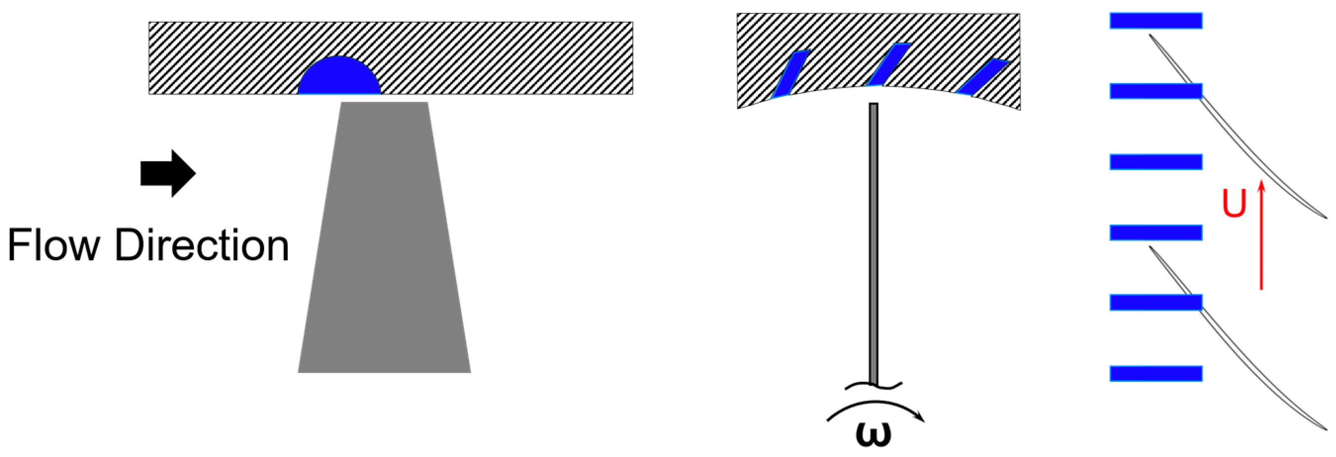
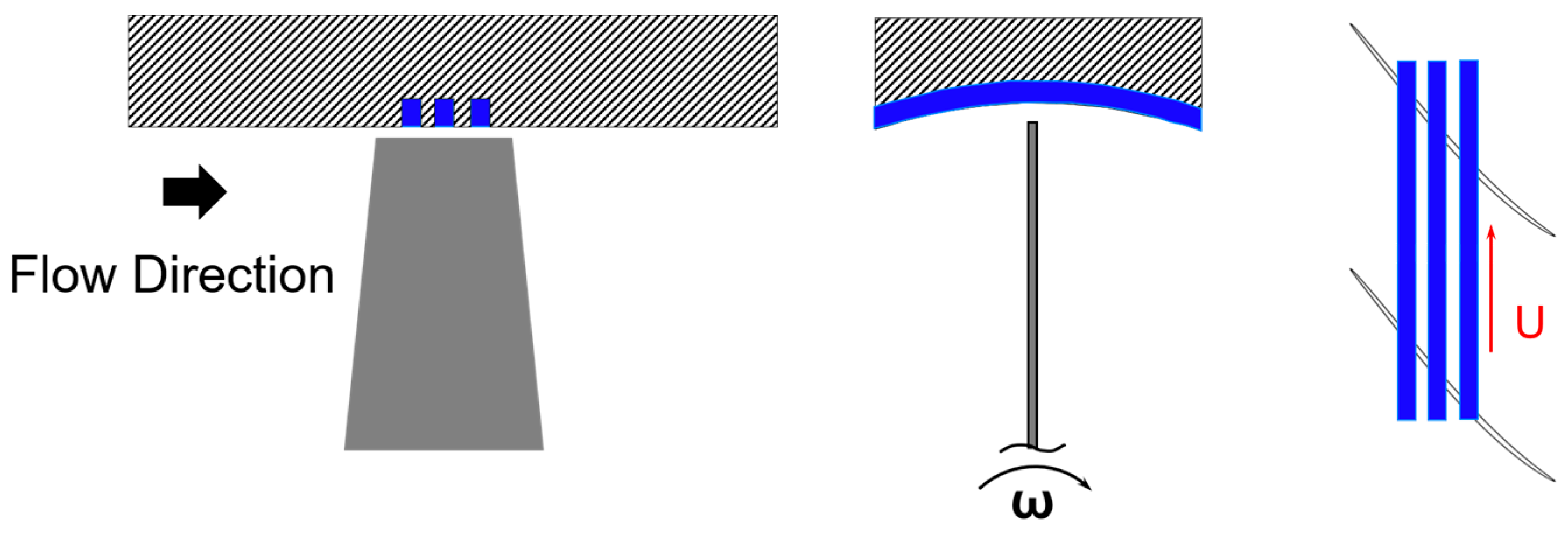
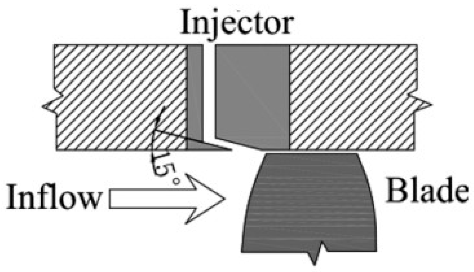
1. Introduction
The axial flow compressor is one of the key components of aeroengines. Its performance directly affects the thrust–weight ratio and thermal efficiency of the engine. In recent years, improvements in aeroengine performance have required higher single_stage pressure ratios or loads, and the average pressure ratio of the next-generation aeroengine increased from 1.23 to 1.56 [
1]. In the face of high maneuverability, a strong reverse pressure gradient, and complex and changeable air intake conditions, the compressor is easily able to enter an unstable state, which brings serious safety threats to the compressor and even the whole aeroengine [
2]. Therefore, widening the stable operating boundary is one of the key technologies of aeroengines.
The stable operation of a compressor is closely related to its internal flow stability. The problem of flow instability in compressors involves many disciplines, such as unsteady flow aerodynamics, turbulence theory, nonlinear dynamical systems and control, and the fundamental theories and key technologies of digital signal processing. It has been one of the research hotspots and difficulties in the field of turbomachinery. It is also a bottleneck problem that restricts improvements in compressor performance [
3]. Over the past several decades of research on compressor stability, significant progress has been made on two fronts. First, theoretical models of compressor instability have been continually refined, and schematic representations of internal flow instabilities have provided direct insights into the underlying phenomena. Second, advances in modern experimental measurement techniques and computational fluid dynamics (CFD) have greatly enhanced the visualization of internal compressor flows, leading to a deeper understanding of the mechanisms driving instability. Modern axial flow compressors are designed with tip loading, a high hub–shroud ratio and a wide chord [
4]. Their strong internal three-dimensional flow characteristics are more prominent; at the same time, problems with their non-axisymmetric blade rings are inevitable in the process of compressor production. The tip clearance between the rotor blade and the compressor casing is necessary to accommodate their relative motion. However, the pressure difference across the blade generates tip leakage flow, which degrades the flow quality near the blade tip and contributes to the onset of instability in the rotor tip region. Since the late 1980s, experimental measurements and three-dimensional numerical simulations have revealed that pressure disturbances first appear at the blade tip under steady to near-stall conditions. With the throttling process, the compressor stall masses in the tip region gradually change from a small scale to a large scale. In view of this phenomenon, although there are different opinions on the mechanism of compressor instability, it is generally agreed that compressor stalls are caused by the deterioration of tip flow fields.
Regarding research on and understanding of compressor instability, delaying the onset of unstable operating conditions has become a research hotspot. When the baseline design fails to meet stability requirements, it becomes necessary to enhance the compressor’s stability margin through appropriate control or design measures to ensure safe engine operation. Widening the stability margin of compressors using control methods is essential to control flow fields and improve the internal flow environment. Up until now, there have been two kinds of control measures for compressors: one is the active control method, and the other is the passive control method, where active control measures typically inject fluid in areas with weak flow energy or extract low-energy fluid to attenuate aerodynamic obstruction, such as Dennis et al. [
5] and Kirtley et al. [
6], or both of the above effects, such as Li et al. [
7]. Although numerous active flow control techniques have been extensively studied, their practical implementation in engineering applications has not yet been realized, primarily due to the added complexity, weight, and cost that they introduce to the engine system. Casing treatment is a form of passive flow control measurement that has been studied for many years. Compared with active control measurements, casing treatment is a control method with zero fluid mass gain, which has the advantages of simple structure, low cost and obvious effects. The casing treatment scheme can be traced back to the 1970s. With the research of casing treatment, its performance potential has been gradually exploited and applied to fans and compressor components, such as EJ200 and GenX [
8], which illustrates the value of casing treatment in compressor or fan stabilization.
Against this background, this study first presents a concise overview of the research history of internal flow instability in compressors. Next, it introduces casing treatment configurations specifically suited for tip_stall_prone compressors, those whose stabilities are compromised by tip_flow deterioration. This study then provides a detailed discussion on the structural optimization and underlying stability mechanisms of slotted casing treatments. Finally, it offers an outlook on future research directions for slotted casing treatment, informed by the latest advances in the field.
2. Compressor Instability
Rotating stall and surge are two typical forms of flow instability phenomena in compressors. Preventing compressors from entering stall conditions has long been a central focus of research. To enable effective control strategies, significant efforts have been devoted to the study of compressor stall precursors. After several decades of research, two distinct types of stall precursors have been identified:
Spike-type precursors, characterized by short-scale disturbance waves detected by dynamic pressure sensors;
Modal-wave precursors, which manifest as long-scale disturbance waves.
Research on compressor flow stall has been carried out, going through three stages:
The first stage (1945~1980) (the stage of exploring flow characteristics of rotating stall phenomenon): In 1945, Cheshire [
9] published an article on centrifugal compressor design and development that first mentioned the compressor stall phenomenon. In 1951, Bullock and Finger [
10] measured the surge characteristics of multi-stage compressors in detail. They used early hot-wire testing techniques and self-developed pressure sensors to capture the unsteady flow in the compressor. Although rotating stall and surge are closely related instability phenomena, studies uncovered new insights, such as the link between compressor instability and the slope of the compressor characteristic curve, as well as the stall hysteresis phenomenon. In the same year, Foley [
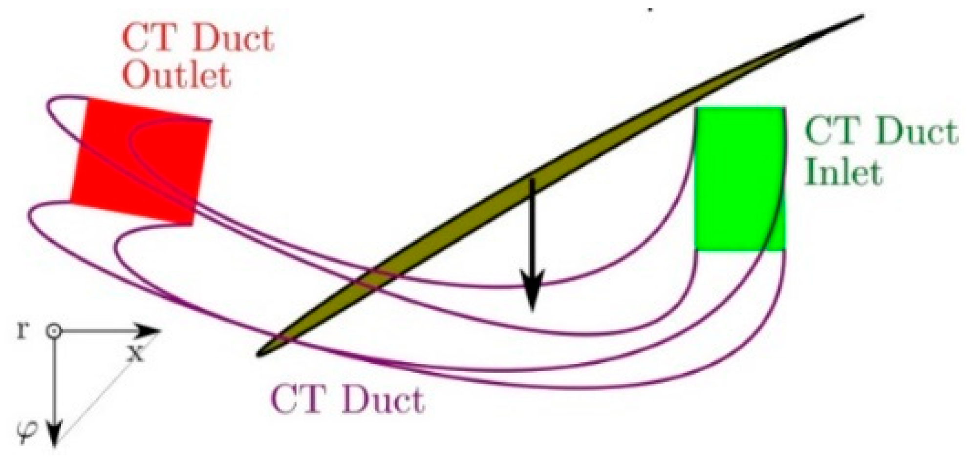
11] gave a diagram of stall in a single-stage compressor, as shown in
Figure 1. Because the figure appeared at a time when researchers believed that the rotating stall and surge had different characteristics of disturbance, the figure was very important.
In 1953, Iura et al. [
12] and Huppert et al. [
13] investigated the characteristics of rotational stall using hot-wire experiments. They described the performance characteristics of rotating stall with throttling, and the difference between partial multi-stall and full-blade single stall was also discussed. Emmons et al. [
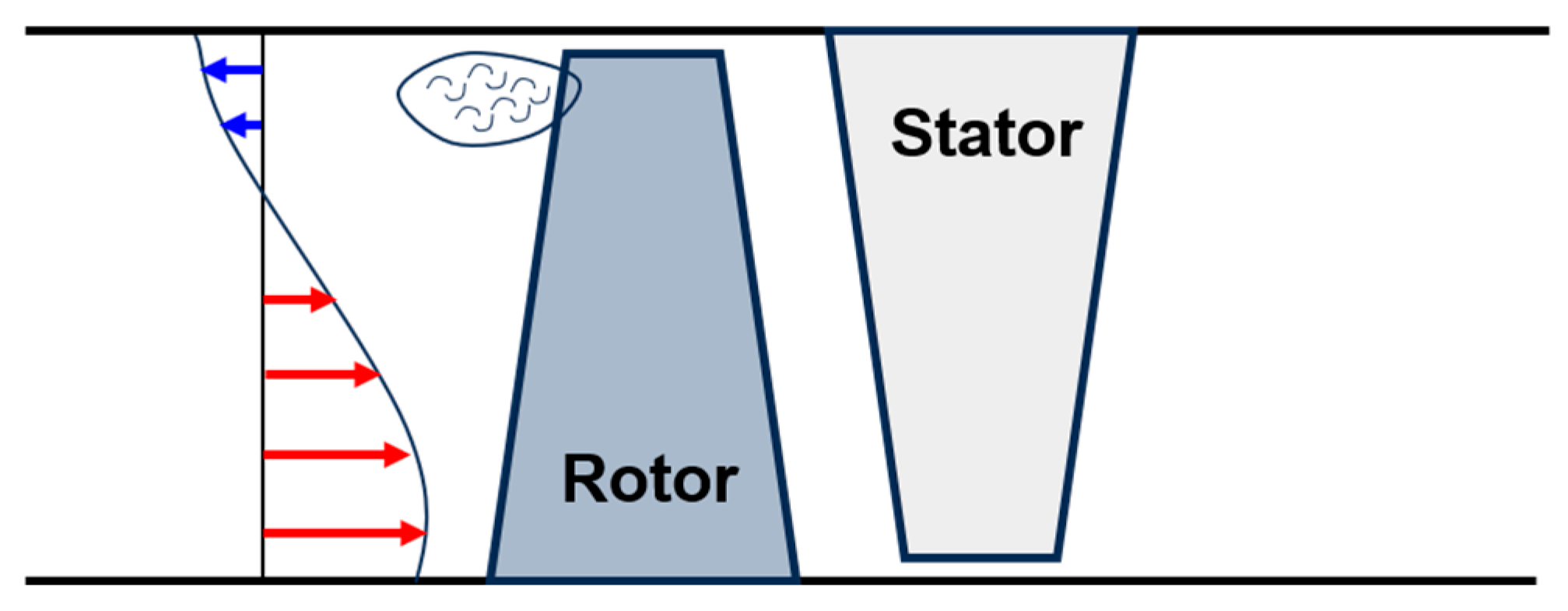
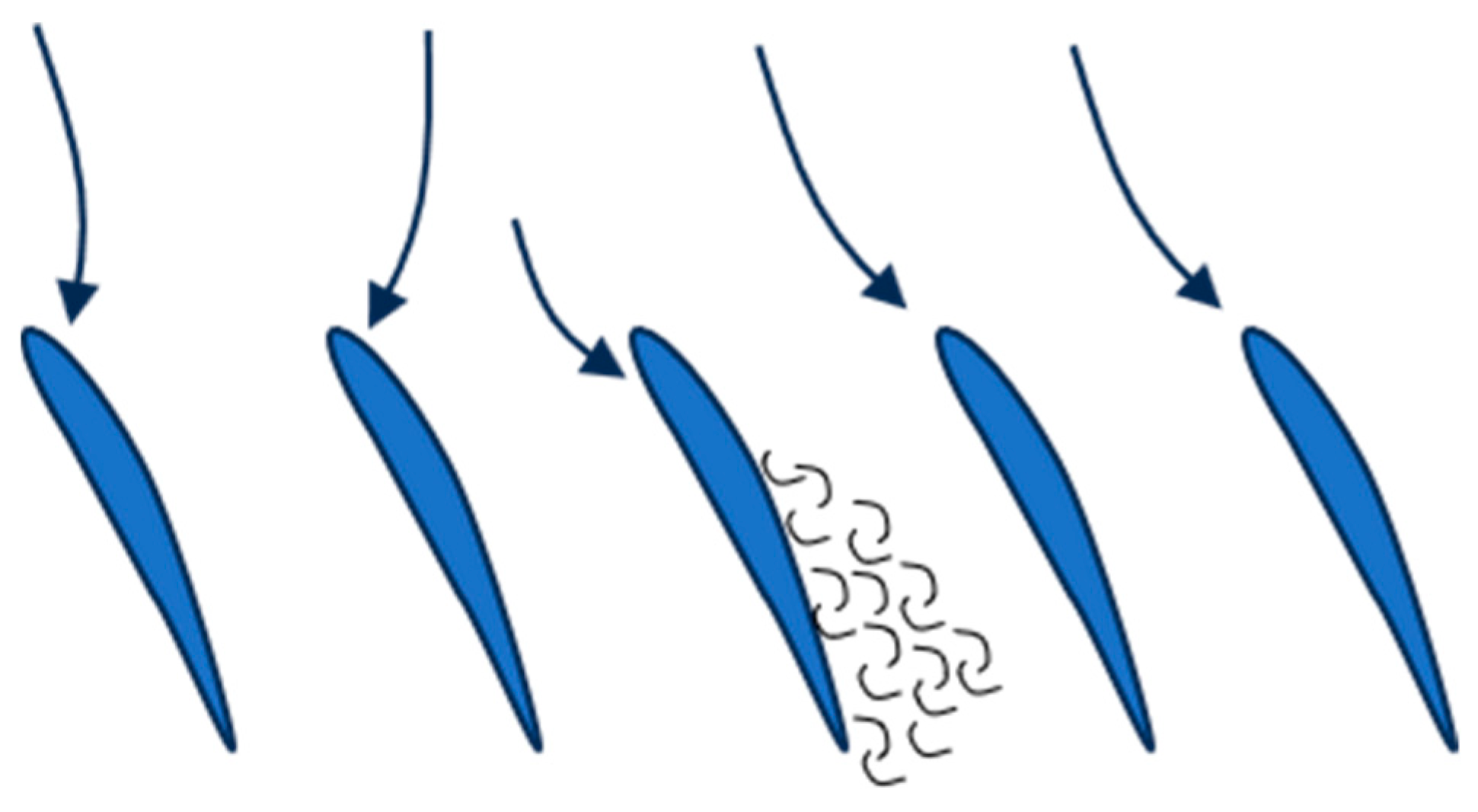
14] first described the rotating stall image of a two-dimensional cascade passage, providing a certain sense of the compressor stall. As shown in
Figure 2, in the throttling process of compressors, the air flow decreased, the axial velocity decreased, and the attack angle of the rotor air flow increased; with further throttling, the compressor stalled. This was a classical theory describing the basic characteristics of rotating stall. With the deepening of research, researchers gradually gained insights into the mechanisms behind the issue. The initiation of the stall cell at a specific blade was primarily triggered by local flow non-uniformities (e.g., slight variations in blade geometry caused by manufacturing, surface roughness, or inlet flow distortion) combined with the peak incidence angle. As the compressor throttled, the flow incidence angle exceeded the critical value, causing flow separation and stall inception at that specific location. As the stall cell formed, it acted as a blockage, creating a positive pressure spike downstream of the stalled region in the relative frame.
From 1955 to 1972 [
15,
16,
17], researchers developed a nonlinear finite perturbation model. Dunham considered the compressor to be at the limit of stable operation when the slope of the total to static pressure ratio line became zero. In the following research, McKenzie proposed a parallel compressor model, based on which Day et al. [
18] verified the theory and extended it using an experimental method. Greitzer [
19] proposed a B-parameter model, in which the flow pressure to inertia force ratio was used to assess the unsteady operation of compressors. Up to now, B-parameter remains one of the most important criteria.
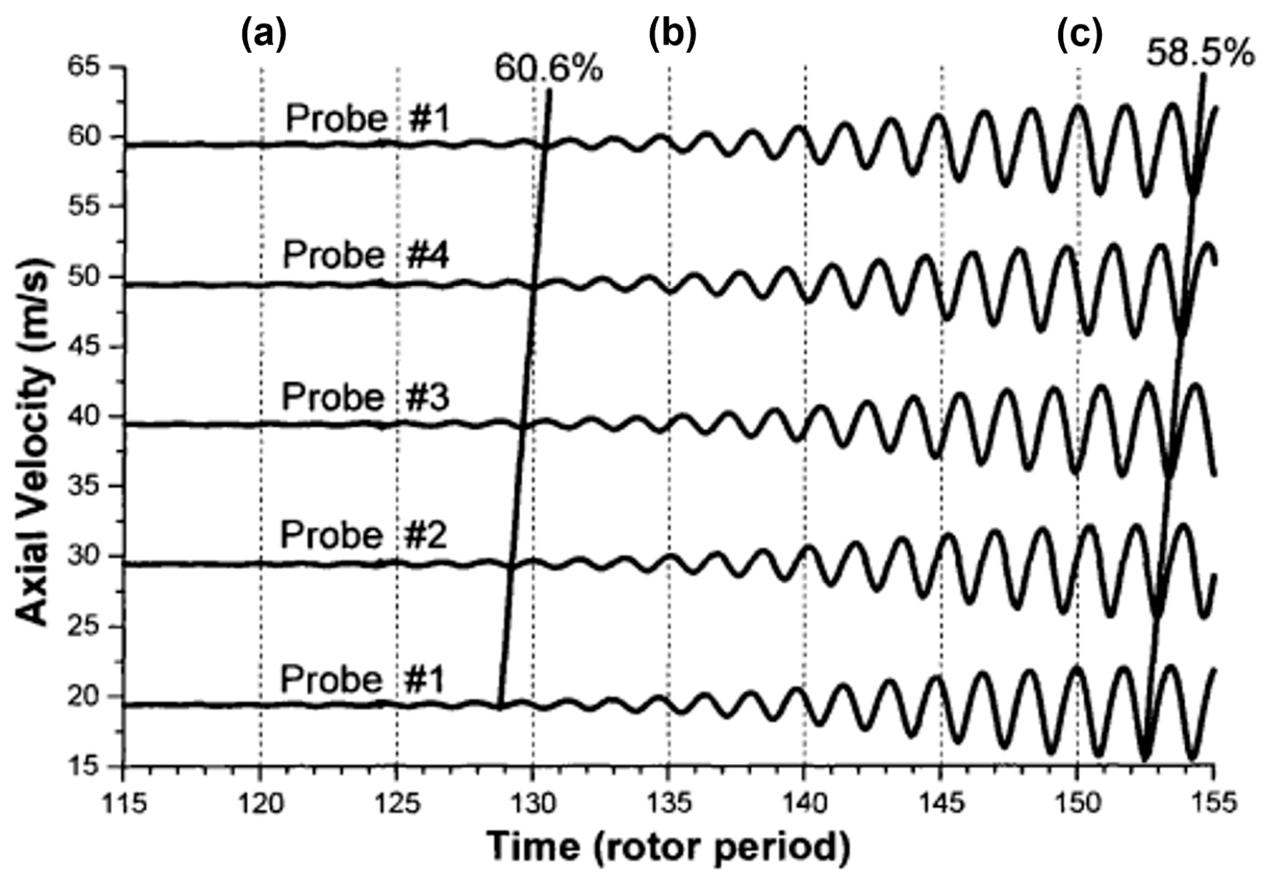
The second stage (1980~2000) (the stage of discovering classical stall precursors): The M-G [
20] rotating stall model, developed on the basis of Greitzer theory, predicted the possibility of low-amplitude circumferential disturbances, i.e., modal-wave stall precursors, occurring before the compressor stall. In 1990, McDougal et al. [
21] used the hot-wire test technique to measure the pre-stall velocity pulsation in a compressor and confirmed the existence of a modal-wave stall precursor for the first time. To show it clearly, a map of the modal-wave stall changing process with rotor period is shown in
Figure 3. Subsequently, Garnier et al. [
2] found modal stall precursors in single-stage low-speed, multi-stage low-speed and multi-stage high-speed compressors.
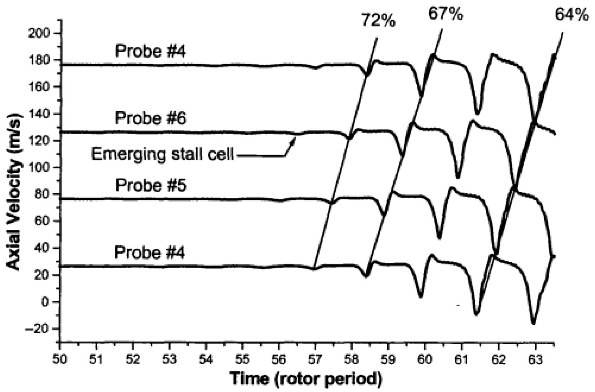
However, the stall precursor type was not the only modal wave type. Day [
22] found a small disturbance that appeared as a spike in the rotor blade tip region. The spike stall signals are shown as axial velocity in
Figure 4. This kind of disturbance is different from the long-scale modal wave. It occurred almost without warning, and once it appeared, it rapidly developed into stall, which was the called spike stall precursor. In subsequent studies, these two types of stall precursors were continuously rammed.
There is no physical model which can accurately assess or predict the type of compressor stall precursor. Due to the diversity in compressor designs, studies on stall types revealed additional precursor behaviors. For instance, Dodds et al. [
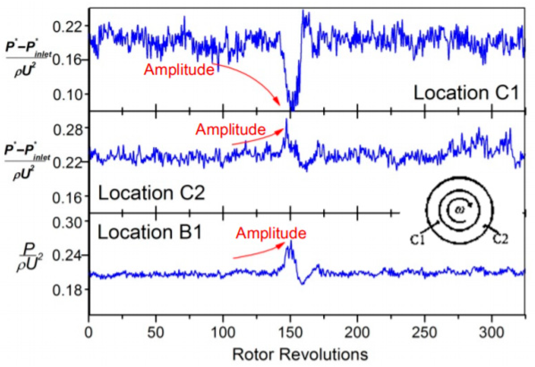
23] identified a stall precursor originating near the blade root through numerical simulations. Similarly, Li et al. [
24,
25] found a low-frequency disturbance occurring at the blade root in a transonic compressor and demonstrated that the disturbance eventually caused a stall in the compressor, as shown in
Figure 5. These new stall characteristics enriched the knowledge and understanding of compressor stall.
The third stage (2000~) (the exploration of mechanisms of spike stall inception): Since most stall precursors in modern compressors first appeared near the rotor blade tips and typically manifest as spike-type precursors, research during this stage primarily focused on the tip-region flow field to elucidate the mechanisms of spike stall inception. Hoying et al. [
26] used a numerical simulation method studying the three-dimensional flow characteristics of single-row blades and first proposed the spike stall precursor criterion: the tip leakage vortex track was perpendicular to the axial direction of a compressor. This was a preliminary description of the spatial characteristics of the spike stall precursor. With the development of computational fluid dynamics, researchers developed a number of theories for inducing the spike stall precursors using numerical simulations, including the theory of leakage vortex breakdown [
27,
28], boundary layer separation theory [
29], the theory of horn-shaped vortex [
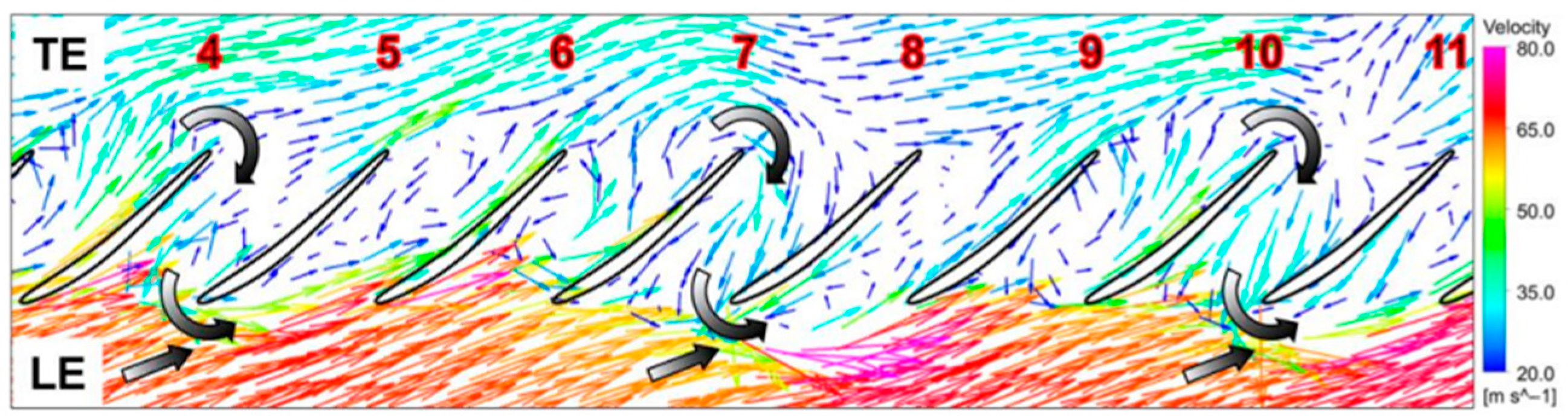
30], and so on. Vo et al. [
31] established a landmark criterion for spike-type stall precursors through unsteady numerical simulations. This criterion comprised two key features: (1) the interface between the tip leakage flow and the incoming main flow becomes parallel to the blade leading-edge plane, and (2) backflow initiates at the trailing-edge plane, originating from fluid in adjacent passages. To show it clearly, the criteria for simulated spike-type stall inception can be found in
Figure 6. In the same year, Deppe et al. [
32] experimentally validated the criterion proposed by Vo, thus consolidating this criterion, which became the theoretical basis in determining spike stall inception. The development of modern experimental techniques provided an opportunity for studying the mechanism of spike stall precursors. In 2018, Brandstetter et al. [
33] studied a 1.5-stage high-speed compressor using an advanced PIV technique. This was also the first time that the structure of horn-shaped vortex and the breakdown of tip leakage vortex had been observed.
Based on a review of the research history of compressor stall, it can be concluded that the stall is closely related to unsteady tip flow. In fact, the unsteady flow is closely related to tip clearance, stage loading and blade operating conditions. It is worth noting that existing studies are often based on design conditions while neglecting the impact of off-design operations. In reality, when operating conditions change, flow structure within casing treatment undergoes significant alterations, leading to nonlinear changes in stage loading characteristics. It is precisely due to this complexity that universal design guidelines are still lacking.
In recent years, the developments in advanced compressor stall analysis methods have led to significant progress in understanding the underlying mechanisms of compressor stall. Both experimental and numerical studies have shown that compressor stall is a multi-scale flow phenomenon: spike-type stall exhibits a pitch-wise spatial scale and a correspondingly short temporal scale, whereas modal stall features a circumferentially extended spatial scale and a longer time scale. Consequently, any model or theory aiming to predict compressor stall must be capable of capturing these two distinct spatiotemporal scales. Traditional approaches, such as eigenvalue-based stability analysis and standard modal decomposition, may, therefore, prove inadequate. In this regard, the authors believe that future research should place greater emphasis on quantitative investigations into the factors governing compressor flow instability. High-fidelity simulation techniques, combined with advanced data-driven methodologies such as big data analytics, will be essential to uncover the fundamental physical mechanisms driving compressor instability.
4. Summary of Slotted Casing Treatment Study
Slotted casing treatment has attracted considerable attention due to its outstanding performance. Since its introduction, researchers have conducted extensive studies using a variety of experimental, numerical, and analytical methods, aiming to optimize its geometric configuration and layout and to elucidate the underlying mechanisms responsible for stall margin enhancement. Consequently, this section focuses on three key aspects of slotted casing treatments: early performance evaluation, structural optimization, and the physical mechanisms by which they extend compressor stability.
4.1. Early Exploration of Slotted Casing Treatment
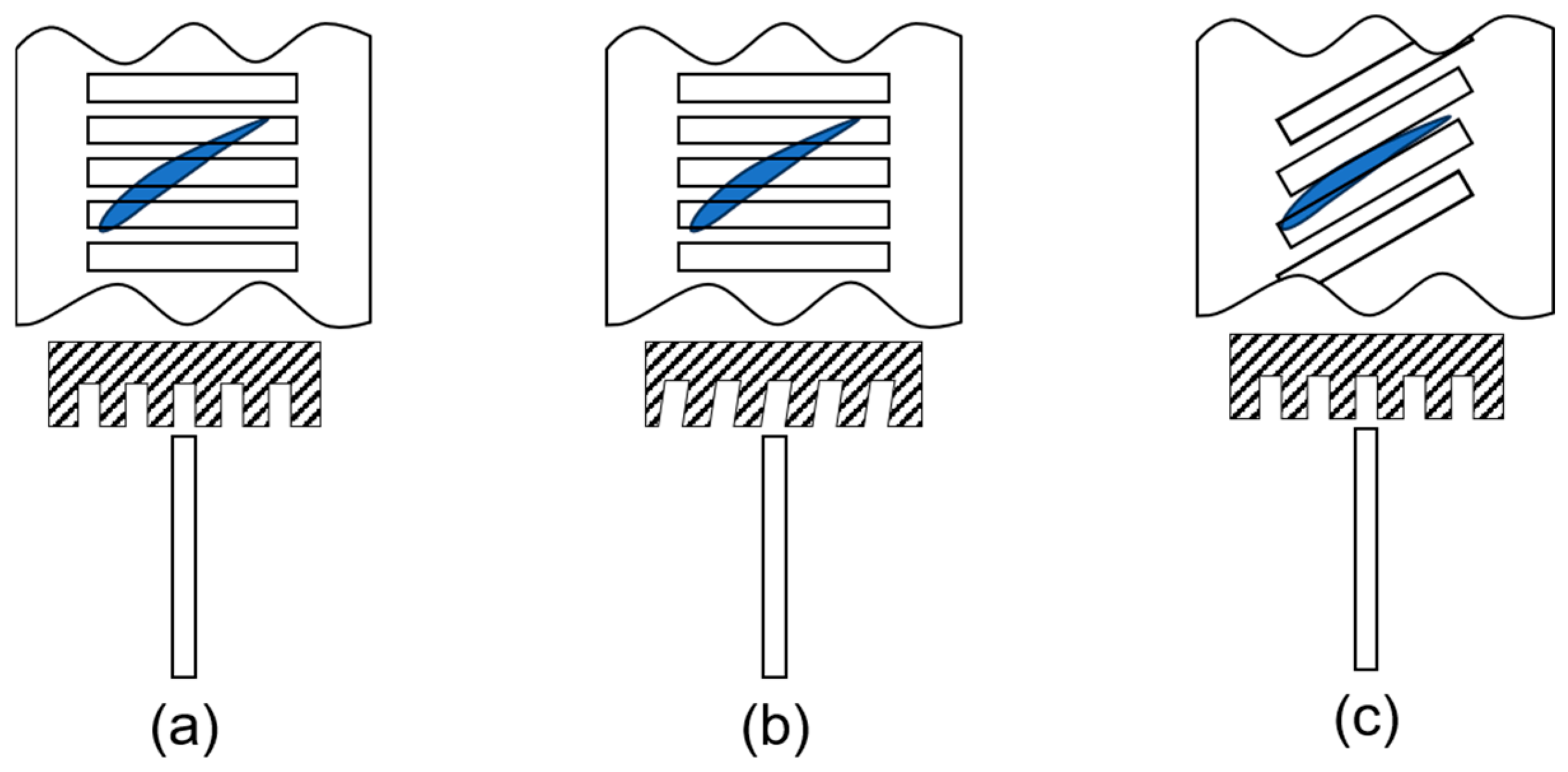
In the early stage, the effects of casing treatment on compressor performance were investigated mainly using experimental methods, regardless of the type of casing treatment. Osborn et al. [
36] were the first to conduct experimental studies on slotted casing treatment. They compared axial slot casing treatment (
Figure 11a), axial slot casing treatment with skewed angle (
Figure 11b), and blade angle axial casing treatment (
Figure 11c). The length of the casing treatment almost covered the axial length of the blade, and the effects of inlet distortion on compressor performance were studied. The experimental results showed that the axial slot casing treatment with skewed angle had the best performance but also the greatest negative effect on the compressor efficiency. All kinds of casing treatments could effectively reduce the effect of inlet distortion on compressor performance. Moore et al. [
48] studied the extending ability of the axial slot casing treatment with skewed angle and circumferential groove, and the results also showed that axial slot casing treatment with skewed angle could improve stall margin better.
Burger et al. [
49] carried out an experimental study on a two-stage fan applied axially skewed slotted casing treatment (similar to
Figure 11b). When the fan operated at 70% of design speed, fan stall was caused by deteriorated tip flow due to high load, and the casing treatment could extend stall margin. However, when the fan worked at design speed, fan stall was caused by severe flow at the root of the blade in the second stage, and the casing treatment did not improve stall margin. In addition, the experimental study also showed that casing treatment can reduce the negative effect of inlet distortion on fan performance. Based on the above results, and combined with the results of Greitzer’s [
45] later research on the criteria for casing treatment, it can be found that the study carried out by Burger indirectly corroborated Greitzer’s conclusion.
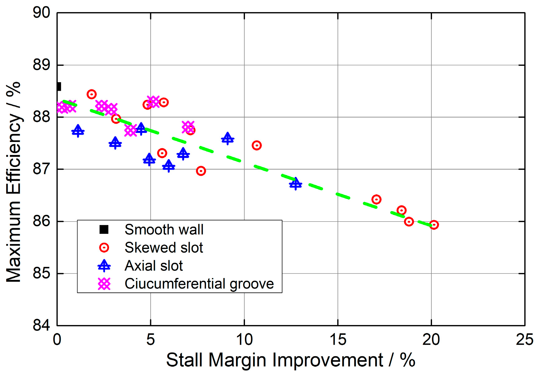
The aforementioned studies not only demonstrated the potential of slotted casing treatment in improving stall margin and resistance to inlet distortion but also revealed a tradeoff between stability enhancement and compressor efficiency. Fujita and Takata [
44] further investigated the relationship between the stability improvement and the effect on compressor efficiency. A series of tests were carried out on the axial slot casing treatment, such as axial skewed slotted casing treatment, axial slot casing treatment and the circumferential groove. The test results are shown in
Figure 12. The horizontal coordinate represented stall margin improvement, the vertical coordinate represented the maximum efficiency of the compressor, and the green dotted line represented the change trend of the maximum efficiency with stall margin improvement. It can be seen that the greater the stall margin improvement, the greater the efficiency loss of the compressor.
In summary, constrained by the research methods available at the time, most of the early studies on casing treatments were conducted through trial and error, primarily focusing on their impacts on compressor performance. Based on extensive experimental research, it was generally concluded that the influence of casing treatments on compressor efficiency exhibited an inverse relationship with their effects on stability margin.
4.2. Structure Optimization of Slotted Casing Treatment
Previous studies shown in the above section basically verified that slotted casing treatment with slot length covering the axial length of the rotor blades could generally achieve a significant stability improvement but, at the same time, led to a reduction in compressor efficiency. How could slotted casing treatment be designed to achieve excellent stall margin improvement while minimizing its adverse impact on compressor efficiency? To address this challenge, research was pursued along two complementary directions: (1) structural optimization of the slotted casing treatment, and (2) elucidation of the underlying mechanisms responsible for its stability enhancement. This section summarizes the key studies focused on the structural optimization of slotted casing treatments.
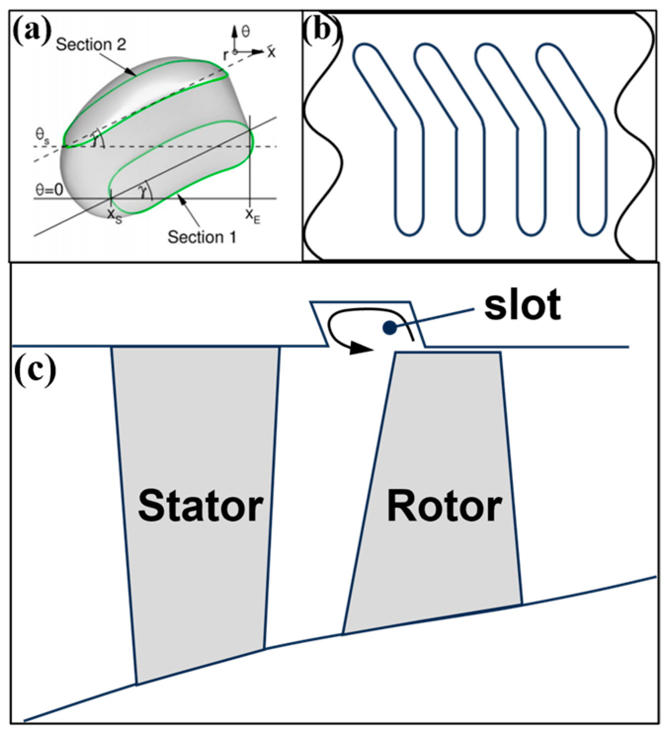
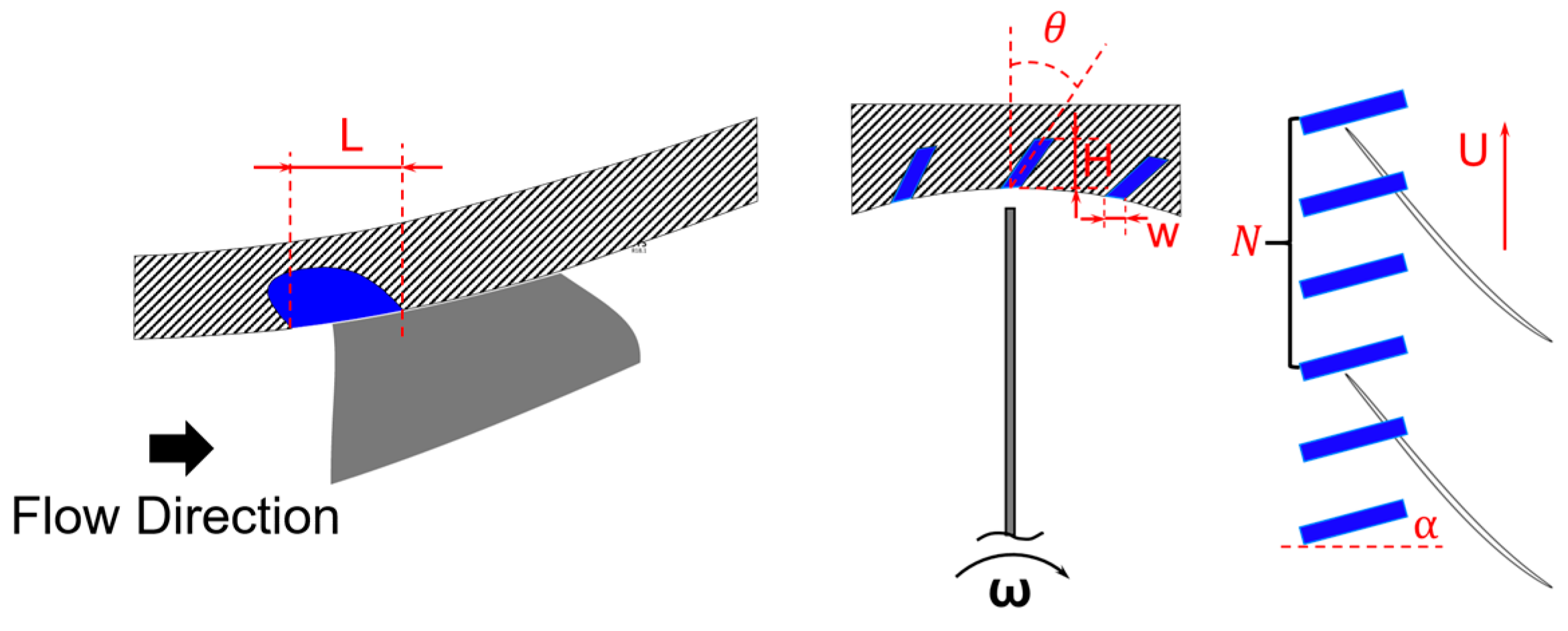
The geometric parameters of slotted casing treatment are as follows: slot length (L), slot width (W), slot depth (h), number of slots (N), skewed angle (θ), stagger angle (α), as shown in
Figure 13.
Moore et al. [
48] first showed that the axial skewed slotted casing treatment had the most remarkable ability in improving stability. Prince et al. [
42] compared and analyzed three different types of casing treatments, which were axial skewed slotted casing treatment, blade angle casing treatment and circumferential grooves; it was also found that the axial skewed slotted casing treatment had the best stability improvement. Although both Moore and Prince had the same conclusion, it still could not guide the skewed direction of slotted casing treatment. Takata and Tsukuda [
43] carried out relatively systematic experimental studies on the axial slot casing treatment, such as axial skewed slotted casing treatment, axial slotted casing treatment, axial reversely skewed slotted casing treatment and blade angle casing treatment. The results showed the following: (1) More than 20% stall margin improvement could be achieved by axial skewed slotted casing treatment. In contrast, the axial reverse skewed slotted casing treatment deteriorated compressor stability. It was because of this study that the researchers no longer carried out relevant research on the axial reverse skewed slotted casing treatment. (2) The effect of the slot depth of axial skewed slotted casing treatment on compressor stability could be neglected. (3) Casing treatment could reduce the sensitivity of the compressor stability to the tip clearance. Prince et al. [
42], Smith et al. [
50], and Fujita et al. [
44] all had similar conclusions.
One of the primary reasons axial slot casing treatment has not been widely adopted in practice is its adverse impact on compressor efficiency, which often exceeds the acceptable limits for engineering applications. As shown in
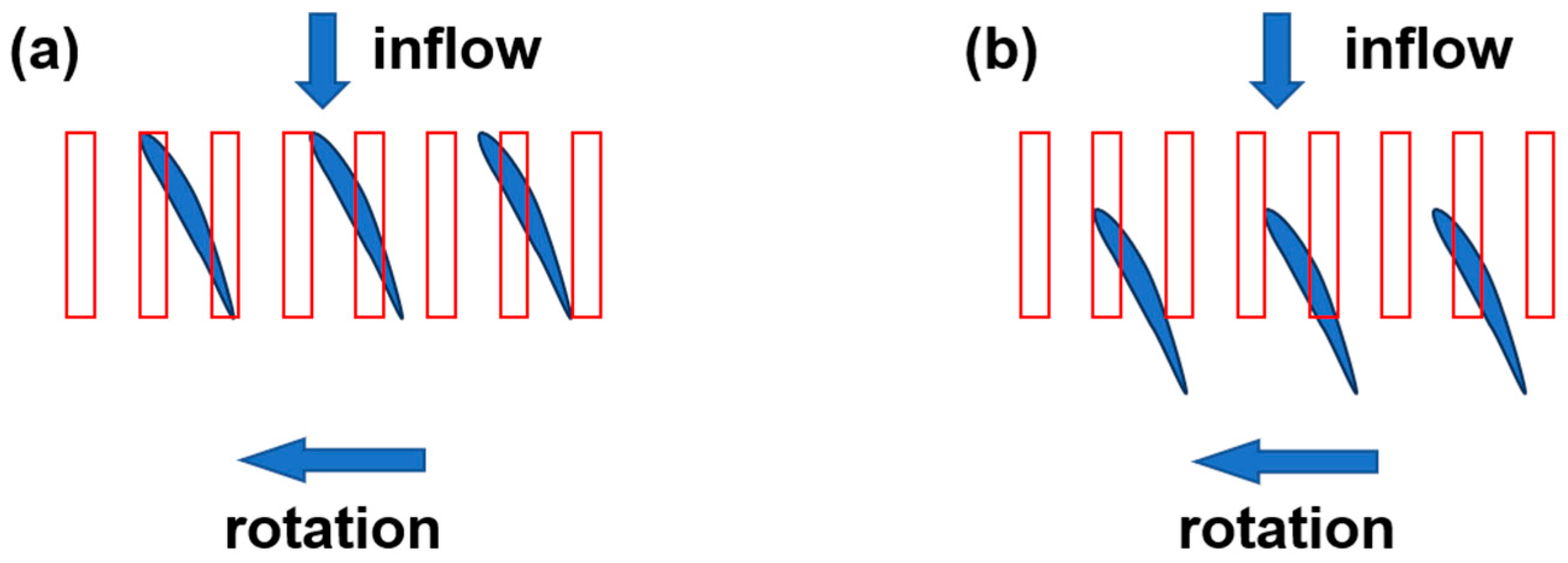
Figure 12, the compressor efficiency is reduced by 2.5%, although a maximum gain of 20% stall margin is achieved. A significant breakthrough occurred in 1999, when Seitz [
51] repositioned the slotted casing treatment axially upstream, such that the slot’s leading edge was located ahead of the blade leading edge. And 25% of the axial length of the blade was covered by slots, as shown in
Figure 14. It was found that the axial slot casing treatment could not only improve the compressor stability but also had little effect on the compressor efficiency. As a result, axial slot casing treatments with this configuration have attracted considerable attention. And, to date, most slotted casing treatments have been designed following this layout.
Brignole et al. [
52] designed a variety of axial slot casing treatment schemes and compared and analyzed the effects of slot width on compressor stability. The results showed that all schemes could improve total pressure ratio and compressor efficiency at design rotating speed. The increment in the total pressure ratio was almost the same, but the scheme with small slot width had the greatest effect on the efficiency, and the efficiency could be increased by 0.6%. Djeghri and Vo et al. [
53] came to a similar conclusion. They studied semi-circular axial slot casing treatment by using numerical simulations, and the results showed the following: (1) when the number of casing treatments was constant, the larger the width of the casing treatment, the better the effect on stability improvement, and the greater the reduction in compressor efficiency; (2) the larger the radial skewed angle of the casing treatment (which is consistent with the direction of blade rotation), the better the effect on stability improvement; (3) the number of slots had little effect on compressor performance, but the relationship between the frequency of slot passing and flow-induced vibration should be paid special attention; (4) with the increase in slot length, stall margin improvement increased, but compressor efficiency decreased; (5) the effect of slot depth on compressor stability and efficiency was not obvious. Du and Seume [
54] used the DOE method to study the effect of the slot length, slot depth, slot number and slot width on the performance of the compressor, and they drew similar conclusions to Djeghri and Vo.
In addition to the exploration and optimization of geometric parameters of slotted casing treatment, researchers also studied the cross-section of slotted casing treatment with the help of an optimization algorithm. The aerodynamic configuration of casing treatment was obtained, taking into account both the ability of extending stall margin and high efficiency of the compressor, as shown in
Figure 15. The related research is available in the literature [
55,
56,
57].
In conclusion, the research results show the following: (1) the forward movement of slots could reduce the negative effect on compressor efficiency; (2) the larger the slot width, the better the stability improvement but the greater the negative effect on compressor efficiency; (3) when the radial skewed direction of slotted casing treatment was consistent with that of blade rotating, the larger the skewed angle was, the stronger the stability improvement was; (4) the longer the slot length, the stronger the stability improvement but the greater the negative effect on the compressor efficiency; (5) the slot depth had little effect on the compressor stability and compressor efficiency; (6) the slot number had little effect on the compressor stability and compressor efficiency, but we should pay attention to the relationship between the slot passing frequency and the flow-induced frequency.
4.3. Study on Mechanisms of Slotted Casing Treatment
In order to design better slotted casing treatments with better performance, it is necessary to find out the mechanisms of stability improvement.
Takata and Tsukuda [
43] carried out detailed experimental measurements on a low-speed compressor test rig to investigate the mechanism of improving stability using slotted casing treatment. They measured the relative flow angle upstream of the leading edge of compressor rotor blades using the hot-wire test technique. The results showed the following: (1) compressor stall was not caused by flow separation, which was induced by large attack angle through analyzing the radial distribution of attack angles; (2) through the analysis of the axial velocity distribution along the radial direction upstream and downstream of the blade, it could be concluded that slotted casing treatment can extend stability because of enhancing flow at the tip region of the blade; (3) through the analysis of the flow within the slots, it was found that the improvement in stall margin primarily resulted from the exchange of momentum between the main flow and the slot flow. However, the author did not specify whether this momentum exchange was axial or radial in nature.
Cheng et al. [
58] designed two different stator blades: one was end-wall stall caused by the larger stagger angle, and the other was to make the compressor “Blade stall”. At the same time, both of them were manufactured with casing treatment at the tip of the stator. They measured the total pressure at the exit of the stator blade, and it was found that the growth of the boundary layer on the end wall can be restrained more effectively by the high-energy fluid ejected from the slots than by the end-wall shear stress. Smith and Cumpsty [
50] measured the velocity distributions downstream of rotor blades, in the blade passage and in the slots. The measured results showed that compressor instability was mainly caused by the flow blockage near the end wall, whereas the flow blockage was improved by momentum exchange through sucking fluid from the trailing edge of the blade into the slot and injecting it into the main flow at the leading edge of the blade. Later, Johnson and Greitzer [
59] demonstrated the conclusions established by Smith and Cumpsty using slot-like treatment on the hub.
Crook et al. [
60] were the first to investigate the mechanism of slotted treatment on the hub in a compressor using numerical simulation methods. They obtained the same conclusions as those of Johnson and Greitzer. The results showed that the slotted end-wall treatment could reduce the flow blockage at the rotor outlet. Hall et al. [
61] first carried out comprehensive numerical studies of slotted casing treatments, and the results showed that the axial slot casing treatment could eliminate the low total pressure and high-vorticity fluid downstream of the blade channel and then reinjected low-vorticity fluid into the blade channel. The ejected fluid increased the tip load, but the flow separation did not occur at the leading edge in the tip region because of the improvement in the blockage behind the passage.
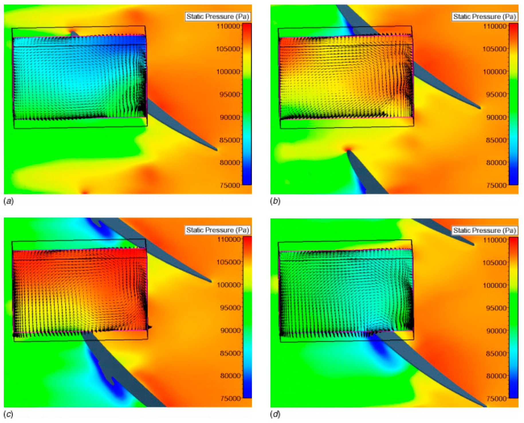
Before 2000, studies on the mechanisms of stability improvement of slotted casing treatment were insufficient because of insufficient boundary conditions, obvious differences between numerical simulation results and experimental results, and the limitation of computational resources. Therefore, further research was needed. However, due to the non-axisymmetric configurations of some slotted casing treatments and the relative motion between casing treatments and rotor blades, flow in the slots was strong, three-dimensional and unsteady, so the steady-state solution could not capture more details because of flow interaction between slots and rotor blades. For this reason, Lu et al. [
62] studied a low-speed compressor rotor using unsteady simulations. The results in
Figure 16 showed that these slotted casing treatments could both extract the reversed tip clearance flow and generate a high-energy injection flow. The combined effect of extraction and injection effectively manipulated the tip clearance flow, delaying upstream migration of the interface between the incoming main flow and the tip leakage flow. Lu et al. also noted that the axial momentum of the main flow decreased as the main flow rate reduced, while the momentum of the tip clearance flow increased with the increase in blade loading. Consequently, the tip leakage flow is directed toward the rotor leading edge. The result was the movement of the interface toward the rotor leading edge plane. On the one hand, with the inclusion of axial skewed slot, axial momentum of incoming flow at the blade tip increased significantly due to the injected flow in front of the rotor leading edge. On the other hand, the momentum of flow through the tip clearance decreased due to the reduced loading of the pressure side when blades were under the slots. This meant the axial skewed slotted casing treatment could help sweep the tip clearance flow trajectory farther aft, delaying the movement of incoming/tip clearance flow interface to the leading-edge plane. Legras et al. [
63] studied the extending mechanisms of axial slot casing treatment in a transonic compressor using numerical simulations and analyzed the mechanism from momentum balance. He pointed out that the suction of slots enhanced the radial transportation of axial momentum, which generated an axial force that resisted the inverse pressure gradient inside the compressor. The injection of the slots induced a change in the axial momentum, the tip flow was energized, delaying the upstream movement of incoming/tip clearance flow interface, and, thus, the flow stability was enhanced.
Jiang et al. [
64] took a single-stage low-speed compressor as the research object; three kinds of slotted casing treatments with different slot numbers were designed, and they studied unsteady interaction mechanisms between slotted casing treatment and blade separation flow. Firstly, the frequency of vortex shedding on the rotor blade was measured using dynamic pressure sensors to guide the selection of slot number. The test results showed that casing treatments with different slot numbers could achieve a stability enhancement; however, only when the interaction frequency between slots and rotor blades was consistent with the vortex shedding frequency could the compressor stability increment and total pressure rise increase the most, and there was no efficiency loss. The research results verified that the slot number effectively affected the unsteady interaction between the slots and the rotor blades and guided the selection of the slot number. But it was limited by the compressor rotating speed. Shivayogi et al. [
65] numerically studied the mechanisms of stability enhancement and flow loss in a transonic rotor with slotted casing treatment. The authors pointed out that low-energy fluid on the suction side of the rotor was injected into the pressure side of the rotor by the self-circulation effect of slots, and the effect gradually increased with the decrease in the compressor flow rate. Therefore, the authors believed that the main mechanism of the stability enhancement was the improvement in end-wall flow conditions under the effect of the slots. However, the large entropy gradient in the tip region caused by the self-circulation effect was the main reason for the reduction in compressor efficiency. Hwang and Kang [
66] investigated the effects of slotted casing treatment on tip leakage flow in a low-speed single-stage compressor with large tip clearance using unsteady numerical simulation. The results showed that (1) the flow blockage caused by the tip leakage flow was eliminated by slots; (2) the interactions between flow in slots and tip leakage flow weakened the unsteady characteristics of the tip leakage flow. In addition, the authors pointed out that the effects of the slots located over blade on the leakage flow were more obvious than those of slots located at the leading edge of the blade. Brandstetter et al. [
56,
67] investigated a transonic compressor using the SPIV measurement technique, and the measurement results showed that the slots weakened the flow blockage at the blade tip and the secondary flow; at the same time, slots weakened the strength of the shock wave. Zhang et al. [
68] investigated the stability enhancement mechanism in a mixed-flow compressor with slotted casing treatment at different clearances. The results showed that casing treatment could reduce the efficiency of the compressor when tip clearance was small but increased compressor efficiency when tip clearance was large. The injection effect of casing treatment played a leading role in stability improvement when the clearance was large, while the suction effect of casing treatment played the main role when the clearance was small. Du et al. [
69] studied the unsteady interaction mechanisms between slotted casing treatment and blade tip flow and found that the casing treatment could effectively weaken the unsteady characteristics of the blade tip leakage flow but could strengthen the unsteady characteristics of the mainstream. At the same time, the casing treatment achieved stability improvement by suppressing the tip leakage flow.
To clearly contrast the distinct stall-margin enhancement mechanisms associated with different casing treatments,
Table 1 summarizes the relevant findings reported by various researchers on the underlying mechanisms of casing treatment.
In summary, although researchers have carried out a large number of studies on the stability enhancement mechanism of slotted casing treatment by means of numerical simulation methods and advanced experimental measurement techniques, the stability enhancement mechanism of the slotted casing treatment and flow loss has not been fully investigated. In addition, there is a large difference in the internal flow structures between high-speed and low-speed compressors, leading to a large difference in the interaction mechanism between slotted casing treatment and blade tip flow. There is no unified understanding of the related mechanism, and further research is still needed.
5. Research Prospect of Slotted Casing Treatment
(1) Advanced aerodynamic design of slotted casing treatment. For decades, slotted casing treatment, such as the parametric design or optimization design of various design concepts, and the design of different profile profiles could achieve obvious stability improvements. However, most of the schemes have negative effects on compressor efficiency, and only several schemes have positive effects or no negative effects on compressor efficiency. The main reasons are as follows: (1) The internal or microscopic flow stability enhancement mechanism of slotted casing treatment is not clear, and there are no design rules. While these studies provide insights into the mechanism of slotted casing treatment, future research should focus on the microscopic flow control mechanisms, such as temporal and spatial evolution of small-scale vortices (corner separation, tip leakage vortex) within slots, governing the tip leakage vortex interaction with the slots. Future research should also focus on how these microflows interact with the main flow to delay or trigger instability, moving beyond just monitoring overall pressure rise. (2) The internal details of compressor design are not clear, and the optimal design of casing treatment should be based on the compressor with different characteristic parameters, for instance, geometric parameters, including aspect ratio and hub-to-tip ratio, flow parameters, including momentum coefficient of injected/inhaled flow, phase difference between blade passing and slot interaction. At present, the design of casing treatment has not been related to the characteristic parameters of compressors. (3) The application of casing treatment changes the aerodynamic performance of the rotor blade tip, and the rotor blade profile is basically designed according to the uniform flow in the initial design. The influence of the self-circulation effect of casing treatment on the inflow is not considered.
Therefore, on the one hand, it is still an urgent problem to establish the correlation between the casing treatment design parameters and the compressor characteristic parameters and customize the advanced design of the casing treatment. On the other hand, the integrated optimization design of the rotor blade and casing treatment should be carried out to ensure the compressor performance [
70,
71]. This design method has shown its advantages and presents certain development potential in the future.
(2) Multi-stage effects of compressor internal flow. Through the above literature review, it is not difficult to find that almost all the research objects focus on single-row rotor blades or single-stage compressors. However, casing treatment suited in single-row or single-stage compressors may not work in multi-stage compressors, mainly because the application of casing treatment will redistribute the load of multi-stage compressors, leading to a shift in stall stage in the multi-stage compressor, which may deteriorate the stability. On the other hand, the self-circulation effects of slotted casing treatment will inevitably affect the downstream flow, and this aerodynamic influence may be continuously amplified after multi-stage evolution and transmission. Furthermore, it has an unpredictable and serious influence on the downstream stage in multi-stage compressors. Therefore, it is necessary to develop a low-dimensional multi-stage compressor simulation method coupled with casing treatment, such as the body force model, which can reveal the aerodynamic mechanisms of slotted casing treatment on flow in a multi-stage compressor.
(3) Advanced experimental measurement and simulation methods. The internal flow in a compressor is three-dimensional and unsteady due to the strong adverse pressure gradient. The application of casing treatment makes the rotor blade tip flow more complex due to the interaction between casing treatment and tip leakage flow, which reduces the applicability of the steady numerical simulation method and traditional steady measurement method. Therefore, it is necessary to propose Large Eddy Simulation (LES) or Delayed Detached Eddy Simulation (DDES) to resolve the unsteady interaction between the tip leakage flow and the casing treatment in the time domain and to refer to the fast response pressure probe measurements or Particle Image Velocimetry (PIV) applied at the casing wall to capture the dynamic flow field inside the slots to reveal the flow mechanism inside the casing treatment [
56,
67]. Experimental techniques, such as high-resolution PIV, enable direct and accurate observation of the coherent structures between the casing treatment and the tip leakage vortex. Moreover, such experiments can account for multi-physics coupling effects that are currently neglected in numerical simulations, thereby providing critical insights for model refinement. Additionally, experimental validation across a wide range of operating conditions helps fill the existing gaps in simulation validation data. In ref. [
72], a high-precision experimental investigation was conducted in a transonic compressor. Unsteady pressure is measured in the casing wall using a cluster of time-resolved transducers with axial and circumferential spatial resolution. It found that the amplitude of the characteristic frequency band induced by the unsteady fluctuation of the tip leakage flow and shock wave is considerably suppressed, which can also be regarded as the stability enhancement mechanism of casing treatment. In addition, the combination of experiment and numerical simulation should be strengthened to calibrate the three-dimensional calculation, and a calibration database should be established to improve the prediction of numerical simulation.
(4) Multidisciplinary research. Compressor design, manufacturing and testing involve a number of disciplines and are extremely complex. The application of slotted casing treatment undoubtedly makes this work more complicated and changes the structural response of rotor blades because of periodic impacts by self-circulation effects on rotor blades. On one hand, the high-temperature flow ejected from slots is equivalent to a heat source, which continuously impacts the rotor blades operating at high speed with strong structural stress, which may change the structural characteristics of the rotor blade. On the other hand, the injected fluid has a significant impact on the flutter and aerodynamic noise characteristics of rotor blades. With the compressor entering the near-stall condition, this effect becomes more obvious. Therefore, as Khalid [
73] has said, it is necessary to carry out studies on the compressor rotor blade structure, aerodynamic noise and flutter coupled with slotted casing treatment.
(5) Application of artificial intelligence. The internal flow of compressor/fan casing treatment is a nonlinear flow problem, and the design of casing treatment includes multi-dimensional parameters, which means the aerodynamic optimization simulation has high cost and lengthy cycles. Artificial intelligence algorithms have shown remarkable ability in dealing with high-dimensional and high-complexity flow field data. Using Neural Networks to predict casing treatment performance based on geometric parameters bypasses expensive CFD calculations. Reinforcement Learning or Genetic Algorithms can automatically optimize the slot pattern for maximum stall margin improvement. These methods can effectively identify the key patterns and laws of flow through automatic learning features and provide more accurate and efficient solutions for tasks such as flow field prediction and turbulence simulation. It can automatically extract high-order features from raw data and establish complex nonlinear relationships, which is especially suitable for dealing with complex flow fields in aerodynamics. The development of AI in the field of compressor casing treatment will push the design paradigm from “Experience-driven” to “Data + Model dual-driven”. For instance, reference [
74] developed an in-house optimization design platform based on the nondominated sorting genetic algorithm II and Kriging surrogate model. The experimental data show that the optimal slot-groove hybrid casing treatment improves the stall margin by 8.42% without generating an efficiency loss. Reference [
75] used the Radial Basis Function (RBF) approximation to construct the surrogate model, and the nondominated sorting genetic algorithm II (NSGA-II) was selected to search for Pareto fronts. Compared with the blade-only optimized blade, the application of ASCT for the blade-integrated optimized blade increases the stall margin improvement from 10.77% to 14.88% and increases the efficiency improvement from −0.3% to −0.12%. From the above research, it can be observed that the “Data + Model dual-driven” significantly enhances the efficiency of optimization design.