Article

Flowfield Structure and Aerodynamic Characteristics of Twin Transverse Jets in Low-Density Hypersonic Crossflow

1
School of Environment and Safety Engineering, North University of China, Taiyuan 030051, China
2
State Key Laboratory of High-temperature Gas Dynamics, Institute of Mechanics, Chinese Academy of Sciences, Beijing 100190, China
3
University of Chinese Academy of Sciences, Beijing 101408, China
*
Author to whom correspondence should be addressed.
Aerospace 2026, 13(10), 865; https://doi.org/10.3390/aerospace13100865
Submission received: 24 August 2026 / Revised: 23 September 2026 / Accepted: 24 September 2026 / Published: 25 September 2026
(This article belongs to the Section Aeronautics)

Abstract

Under low-density hypersonic flight conditions, conventional aerodynamic control authority is markedly reduced, making transverse jets a promising approach for direct force control. However, the interaction mechanisms of multiple jets under such conditions remain unclear. In this paper, numerical simulations were employed to investigate the flowfield structure, aerodynamic characteristics, and their coupling-induced variations in twin transverse jets under low-density hypersonic crossflow. The results show that the twin-jet flow is not a simple superposition of two isolated single jets, but exhibits distinct near-wall separation, compression, and wake evolution patterns induced by jet–jet interaction. The upstream jet aerodynamically shields the downstream injector, modifies its local crossflow conditions, and consequently enhances downstream jet penetration and wake development. Conversely, the downstream jet affects the upstream flow through the near-wall boundary layer by pushing the primary separation region farther upstream, restricting the free expansion of the upstream jet, and intensifying compression and recirculation in the inter-jet and near-wake regions. Macroscopically, the aerodynamic force analysis reveals that the control force coefficient increases with jet strength, whereas the control force amplification factor decreases continuously. Compared with a single-jet configuration at matched total jet mass flow rate, the twin-jet configuration yields a higher control force and a lower total moment. These findings provide fundamental physical insights into the design and optimization of multi-jet direct force control systems under low-density hypersonic flows.

1. Introduction

As near-space hypersonic vehicles maneuver over a wide range of flight conditions, the effectiveness of conventional aerodynamic control surfaces decreases markedly with increasing altitude and decreasing atmospheric density [1]. To compensate for this loss of control authority, direct force control using transverse jets has been widely adopted for attitude control and trajectory correction [2]. A transverse jet acts as a localized aerodynamic obstacle [3]: it provides direct jet reaction force, induces a high-pressure separation region upstream of the jet through shock-wave/boundary-layer interaction, and forms a low-pressure wake region downstream. This redistribution of surface pressure generates additional aerodynamic forces and moments.
To understand the physical mechanisms underlying direct force control based on transverse jets, the flowfield structure and aerodynamic characteristics of a single transverse jet have been studied extensively [4,5]. Numerical and experimental studies have identified the key shock structures, separation features, and wake dynamics associated with jet–crossflow interaction. For example, Viti et al. [6] identified the barrel shock, bow shock, and separation-induced shock as the dominant compression structures in the flowfield and related the downstream low-pressure wake to the leeward side depression of the barrel shock and the wake vortices. Zhang et al. [7] further revealed the unsteady evolution of moving shocks within the upstream separation region and its coupling with large-scale shear-layer vortices. Meanwhile, Sun and Hu [8] showed that shock impingement can induce herringbone separation bubbles and reattachment valleys, and trailing counter-rotating vortex pairs near the wall. Large-eddy simulations by Xiao et al. [9] also showed that increasing jet pressure ratio enlarges the upstream recirculation zone and strengthens both the shock structure and the streamwise vortices in the wake. From an aerodynamic perspective, DeSpirito [10] pointed out that transient pulsed lateral jets can significantly modify both the control force and the lateral moment response. Despite these advances, recent studies have also shown that a single jet at high-pressure ratios, although capable of strong penetration, often generates a strong detached bow shock and an extended low-pressure wake [11], thereby leading to additional drag, deterioration of the local thermal environment, and nonlinear aerodynamic responses [12,13,14,15].
Against this background, multi-jet configurations [16] have attracted increasing attention as a potentially more effective flow control strategy than the single-jet arrangement. Their key advantage lies in the mutual interaction between injectors. The upstream jet can aerodynamically shield the downstream injector, displace the boundary layer [17], modify the local crossflow conditions, and thereby improve the local pressure distribution and overall control effectiveness. Existing studies have shown that such interactions can substantially change the penetration, mixing, vortex evolution, and aerodynamic response of the jet system. For tandem transverse jets, Lee et al. [18] showed that the upstream jet imposes a strong blocking effect on the downstream jet, leading to stronger expansion and deeper penetration, together with higher mixing rates than in the single-jet case, albeit at the cost of increased total pressure loss. Pudsey and Boyce [19] further showed that, under the same total jet area, an array of multiple small jets can achieve better overall penetration and mixing performance than a few large jets, because the subsonic region between injectors and the wake vortices enhance the effective momentum ratio and interfacial mixing of the downstream jets. Radhouane et al. [20] demonstrated that aerodynamic shielding can also reshape the downstream vortex system, causing the counter-rotating vortex pairs of the twin jets to merge gradually into a single large-scale vortex structure in the far field. More recently, Maikap [21] reported that a streamwise tandem twin-jet configuration generates an additional bow shock ahead of the downstream injector and more complex inter-jet vortex structures, while significantly enhancing the penetration of the downstream jet. From the perspective of aerodynamic characteristics, Chen et al. [22] showed that the force and moment amplification factor follow different trends with changing jet parameters, and that only the first jet interacts directly with the freestream, whereas the downstream jets evolve within the disturbed flowfield generated by the preceding jet. These studies collectively indicate that multi-jet systems cannot be regarded as a simple superposition of isolated single jets, as jet–jet interaction fundamentally alters both flow organization and the aerodynamic response.
Previous investigations of direct-force control under low-density hypersonic conditions have predominantly focused on single-injector configurations. Although a single transverse jet can generate a pronounced aerodynamic response, its influence is generally highly localized and is accompanied by strong shock-wave/boundary-layer interaction and concentrated wall-pressure loading. Distributing the available jet supply among multiple injectors therefore provides a potential approach for modifying the spatial distribution of the aerodynamic loading and the resulting control response under a comparable overall jet-supply level.
For streamwise tandem jets, however, the aerodynamic response cannot be regarded as a simple superposition of two isolated single jets. The upstream jet modifies the local crossflow and boundary-layer state encountered by the downstream injector, while the downstream jet can in turn affect the upstream separation region and the pressure field between the two injectors. Consequently, the aerodynamic response of the tandem system depends not only on the overall jet input, but also on the interaction between the two jets and the manner in which the jet supply is distributed between the upstream and downstream injectors. Although previous multi-jet studies have reported significant changes in jet penetration and overall flowfield structure, the mechanisms by which tandem-jet coupling modifies the wall-pressure distribution and subsequently affects the aerodynamic force and moment remain insufficiently understood. Under low-density hypersonic conditions, rarefaction-related effects may become increasingly relevant as the freestream density decreases and can influence the applicability of conventional continuum-flow descriptions [23]. Previous studies have also shown that variations in freestream density can modify the flow structure and aerodynamic characteristics of lateral-jet interactions [24], while finite-rate chemical effects under high-enthalpy conditions may further influence the jet–crossflow interaction through changes in the local thermodynamic state [25]. Systematic investigations of tandem-jet aerodynamic coupling under such conditions therefore remain limited.
Motivated by these considerations, the present study investigates a streamwise tandem twin-jet configuration over a flat plate using three-dimensional reacting RANS simulations under low-density hypersonic freestream conditions. The analysis first focuses on the coupling between the upstream and downstream jets and its influence on the flow structure and wall-pressure redistribution. The total pressures of the two jets are then varied independently to examine how different jet-strength allocations modify the wall-pressure loading and, consequently, the resulting aerodynamic force and moment. By establishing the connection between twin-jet coupling, pressure redistribution, and aerodynamic response, the present study provides a physical basis for evaluating the control characteristics of multi-jet direct-force-control systems.

2. Numerical Methods

2.1. Governing Equations and Physical Models

A finite volume method is employed in the present study. The three-dimensional compressible Navier–Stokes equations with chemical reaction source terms are solved to capture complex shock interactions and chemical nonequilibrium effects. The governing equations consist of the conservation equations of mass, momentum, total energy, and species mass fractions, which are written as:
∂ ρ ∂ t + ∇ · ρ u = 0
∂ ρ u ∂ t + ∇ · ρ u u + p I = ∇ · τ
∂ ρ E ∂ t + ∇ · ρ E + p u = ∇ · τ · u − q
∂ ρ Y k ∂ t + ∇ · ρ Y k u = − ∇ · J k + ω ˙ k , k = 1 , 2 , … , N s ,
where ρ is the density, u is the velocity vector, p is the pressure, I is the unit tensor, E is the total energy per unit mass, Y k is the mass fraction of species k, N s is the number of species, τ is the viscous stress tensor, q is the heat flux, J k is the diffusion flux of species k, and ω ˙ k is the chemical production rate of species k.
The pressure is obtained from the ideal-gas equation of state for a multi-species mixture:
p = ρ R mix T
R mix = R u ∑ k = 1 N s Y k W k ,
where R u is the universal gas constant and W k is the molecular weight of species k.
To close the governing equations, appropriate models are introduced for turbulent transport and finite-rate thermochemical processes. The turbulence effects are described within the Reynolds-averaged Navier–Stokes (RANS) framework using the one-equation Spalart–Allmaras model [26]. It should be noted that the SA model has certain limitations in strongly three-dimensional separated flows involving strong adverse pressure gradients and free shear layers, and uncertainty may therefore remain in the detailed prediction of the separation extent, shear-layer evolution, and local vortical structures. The present study, however, focuses primarily on the mean flowfield structure, wall-pressure redistribution, and overall aerodynamic characteristics. Under the corresponding single-jet condition, the present SA-RANS framework provides reasonable agreement with the measured wall-pressure distribution, supporting its use for the mean aerodynamic quantities considered here. The SA model is therefore retained to maintain consistency with the previously validated numerical framework and to provide a uniform turbulence treatment for the systematic parametric calculations. For the thermochemical treatment, the reaction mechanism is selected to be consistent with the high-temperature freestream conditions employed in our previous experimental studies [27,28], thereby enabling direct comparison with future experimental measurements.
A nine-species, eighteen-reaction finite-rate chemical model is adopted under a single-temperature assumption. The species considered are H2O, O2, H2, N2, OH, H, O, H2O2 and HO2. In the present context, chemical nonequilibrium refers to the finite-rate production and consumption of chemical species, whereas thermal nonequilibrium among translational, rotational, vibrational, and electronic energy modes is neglected. The complete reaction mechanism and Arrhenius parameters are provided in reference [29]. The adopted thermochemical model has been validated against experimental data available in the literature [27,28]. The thermodynamic properties of individual species are evaluated using the McBride polynomial relations [30], while the viscosity and thermal conductivity of the mixture are determined using Sutherland’s law in conjunction with Wilke’s mixing rule.

2.2. Computational Domain and Boundary Conditions

Only half of the computational domain is considered because of the geometric symmetry of the flat-plate configuration and the associated flowfield. Our previous numerical–experimental comparison showed good agreement at an angle of attack of 0 ° [27]. At higher angles of attack, however, the reduced density on the leeward side enhances rarefaction effects and leads to increasing discrepancies between Navier–Stokes predictions and experimental measurements. The present study is therefore restricted to 0 ° .
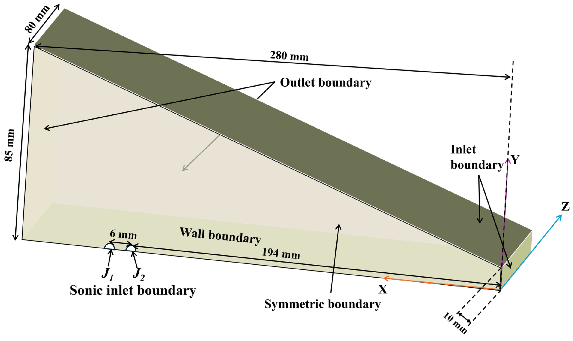
As shown in Figure 1, the computational domain has a length of 280 mm and a width of 80 mm, and its height increases from 10 mm at the inlet to 85 mm at the downstream end. The computational domain starts from the leading edge of the flat plate, with two jet orifices, each 1 mm in diameter, located 194 mm and 200 mm downstream of the leading edge, corresponding to a streamwise spacing of 6 mm. The hypersonic boundary layer develops naturally along the flat plate before reaching the jet-interaction region, rather than being prescribed through a local inflow profile. The flat plate is mounted on the bottom surface of the computational domain, which is treated as an isothermal no-slip wall. Supersonic inflow boundaries are imposed on the top and right sides, sonic inflow conditions are imposed at the two jet orifices, far-field boundaries are applied on the left and lateral sides, and the centerline of the flat plate is treated as a symmetry boundary.

2.3. Freestream and Jet Conditions

Table 1 summarizes the freestream conditions and species mass fractions adopted in the present study. The freestream condition is derived from our previous experiments in the JFX detonation-driven shock tunnel and is not intended to represent the atmospheric state at a specific flight altitude. The freestream Mach number M ∞ is 6.4, with a velocity u ∞ of 3228 m/s, static pressure p ∞ of 403 Pa, static temperature T ∞ of 509 K, and density ρ ∞ of 2.16 × 10 − 3 kg/m3.
Under the freestream conditions listed in Table 1, the estimated mean free path is approximately λ ∞ ≈ 3.6 × 10 − 5 m . Based on the characteristic boundary-layer thickness, the corresponding Knudsen number is K n D ≈ 8.4 × 10 − 3 , indicating that the near-wall flow considered in the present study remains predominantly within the near-continuum regime. Together with the previous numerical–experimental agreement at 0 ° angle of attack [27], this estimate supports the use of the continuum-based RANS approach for the present analysis of wall-pressure redistribution and aerodynamic loads.
At the jet orifices, the total pressure P 0 , j , total temperature T 0 , j , and species composition are prescribed, with pure N 2 used as the jet medium. Under the pressure ratios considered here, the jet flow is choked, and the exit Mach number is approximately unity. The nominal sonic static pressure and temperature listed in Table 2 are obtained from the prescribed total conditions using the standard isentropic relations.
Table 2 summarizes the jet conditions considered in the present study. J 1 and J 2 denote the downstream and upstream injectors, respectively. P 0 , j 1 and P 0 , j 2 represent the downstream and upstream total pressures, respectively, while P j 1 and P j 2 are the corresponding static pressures. T 0 , j and T j represent the total and static temperatures of the jet, respectively. The jet total temperature is maintained at 300 K for all cases, and the nominal sonic static temperature is approximately 250 K. Among all cases considered, Cases 4, 11, and 14 correspond to the single-jet configurations. To analyze the interaction between the twin jets, the pressure settings of the upstream and downstream injectors are varied parametrically. First, the total pressure level of the twin-jet system is varied while keeping the mass flow rates of the upstream and downstream jets identical (Cases 6, 10, and 16), in order to examine the effect of the overall jet strength on the flowfield evolution of the twin-jet system. Second, the influence of each jet on the other is examined separately by fixing either the upstream or downstream jet total pressure at 2.3 bar and varying the other one independently (Cases 6, 9, and 15; Cases 6, 7, and 8). Third, the overall aerodynamic forces of the twin-jet and single-jet configurations (Cases 6 and 11) are compared at the same combined jet total pressure of 4.6 bar. Finally, while keeping the total pressure of the twin-jet system fixed at 8 bar, the pressure is allocated between the upstream and downstream jets in different ratios (Cases 2, 3, 10, 12, 13, and 14) to examine the effect of jet-pressure allocations on the surface aerodynamic force characteristics.

2.4. Grid Independence and Validation

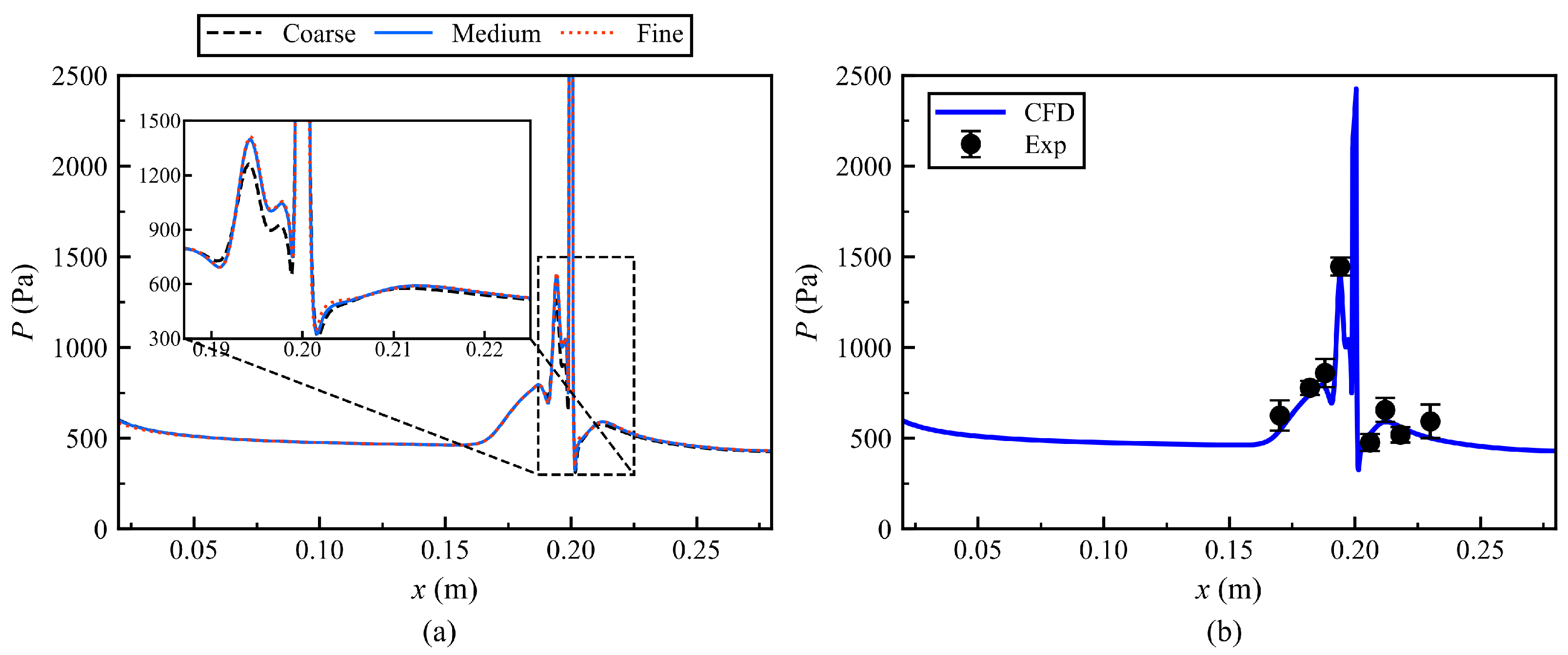
A grid-independence study is performed for the single-jet Case 4 ( P 0 , j 1 = 2.3 bar ) to assess the sensitivity of the numerical results to grid resolution. Three grids are considered, with resolutions of 170 × 45 × 50 (Coarse), 220 × 75 × 90 (Medium), and 330 × 100 × 120 (Fine). For all three grids, the first near-wall cell height is fixed at 1 × 10 − 5 m . As shown in Figure 2a, the wall-pressure distributions obtained using the three grids show good agreement in the strongly disturbed region near the jet exit, indicating progressive convergence of the pressure field with grid refinement. Taking the medium grid as the reference, the coarse grid exhibits a maximum pressure deviation of 11.25%, whereas the fine grid differs by only 0.15% on average. Considering both numerical accuracy and computational cost, the medium grid is therefore adopted for the subsequent simulations. The wall y + distribution of the adopted medium grid was further examined to assess the near-wall resolution. The results confirm that y + remains below 1 throughout the computational wall, including the regions immediately adjacent to the jet-orifice lips where relatively strong local velocity gradients are present. This confirms that the adopted mesh provides adequate near-wall resolution for the wall-resolved SA-RANS calculations conducted in the present study.
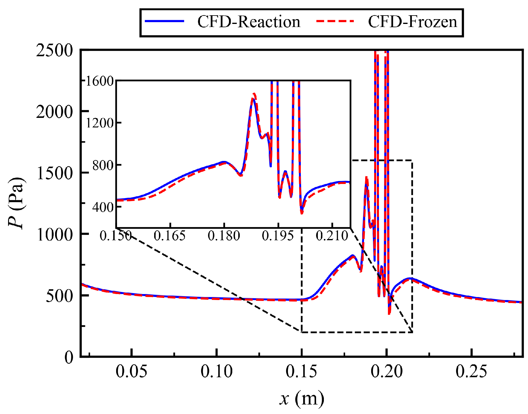
To further evaluate the reliability of the numerical method, the wall-pressure distribution obtained using the medium grid was compared with the experimental data obtained from our previous study under the corresponding single-jet condition [27], as shown in Figure 2b. The numerical results show good agreement with the experimental measurements in terms of both the overall pressure level and the streamwise pressure evolution, demonstrating that the present numerical method can effectively capture the main aerodynamic characteristics of the jet–crossflow interaction. Meanwhile, Figure 3 presents the wall-pressure evolution obtained without the chemical reaction source terms. It can be observed that the reacting and frozen-chemistry calculations exhibit similar overall wall-pressure trends, indicating that the dominant flowfield behavior is primarily governed by the aerodynamic interaction between the jet and crossflow. However, noticeable quantitative differences remain in the jet-interaction region, with the maximum local relative difference in the centerline wall pressure reaching approximately 14.93%. Since the aerodynamic interaction force and pitching moment investigated in this study are both obtained by integrating the wall-pressure distribution, the above differences indicate that finite-rate chemistry can exert a certain influence on the quantitative prediction of the aerodynamic response. Meanwhile, under otherwise identical numerical settings and convergence criteria, the reacting calculation required approximately 100% more computational time than the corresponding frozen-chemistry calculation. Nevertheless, considering that the aerodynamic quantities of interest in the present study are relatively sensitive to chemistry-induced changes in the wall-pressure distribution, this additional computational cost was considered acceptable for maintaining the accuracy of the aerodynamic predictions.

3. Flowfield Structure and Interaction of Twin Jets Under Different Jet Pressure Conditions

3.1. Typical Flowfield Structure

The characteristic flow structures of the twin-jet configuration are first examined by comparison with the corresponding single-jet case. Figure 4 presents the symmetry-plane Mach number contours for the twin-jet Case 6 and the single-jet Case 11 under the same combined jet total pressure. Both configurations exhibit the canonical structures associated with transverse jet–crossflow interaction, including the leading-edge shock, upstream separation shock, detached bow shock, barrel shock, Mach disk, and near-wall recirculation region. The principal difference is that the twin-jet configuration produces a broader blockage region upstream of the injectors. Consequently, the adverse pressure gradient extends farther upstream and the boundary layer separates earlier than in the single-jet case.
After issuing from the orifice into the crossflow, the underexpanded jet undergoes rapid expansion because its static pressure is much higher than the local ambient pressure. Subsequent overexpansion causes the jet core pressure to fall below the ambient level, and a Mach disk forms at the end of the barrel shock to restore pressure equilibrium. As shown in Figure 4, in the twin-jet configuration, the downstream jet exhibits a more vertically extended barrel-shock structure than the upstream jet. This asymmetric development is mainly caused by the shielding effect of the upstream jet. Specifically, the upstream jet and its bow shock deflect the freestream and displace the separated boundary layer upward, thereby reducing the local crossflow Mach number and dynamic pressure at the downstream injector. The resulting increase in effective momentum ratio promotes deeper penetration of the downstream jet. In contrast, the single-jet configuration, because of its more concentrated local momentum input, exhibits a higher effective pressure ratio and a larger wall-normal penetration height, which in turn produces a stronger detached bow shock and a larger adverse pressure gradient ahead of the injector.
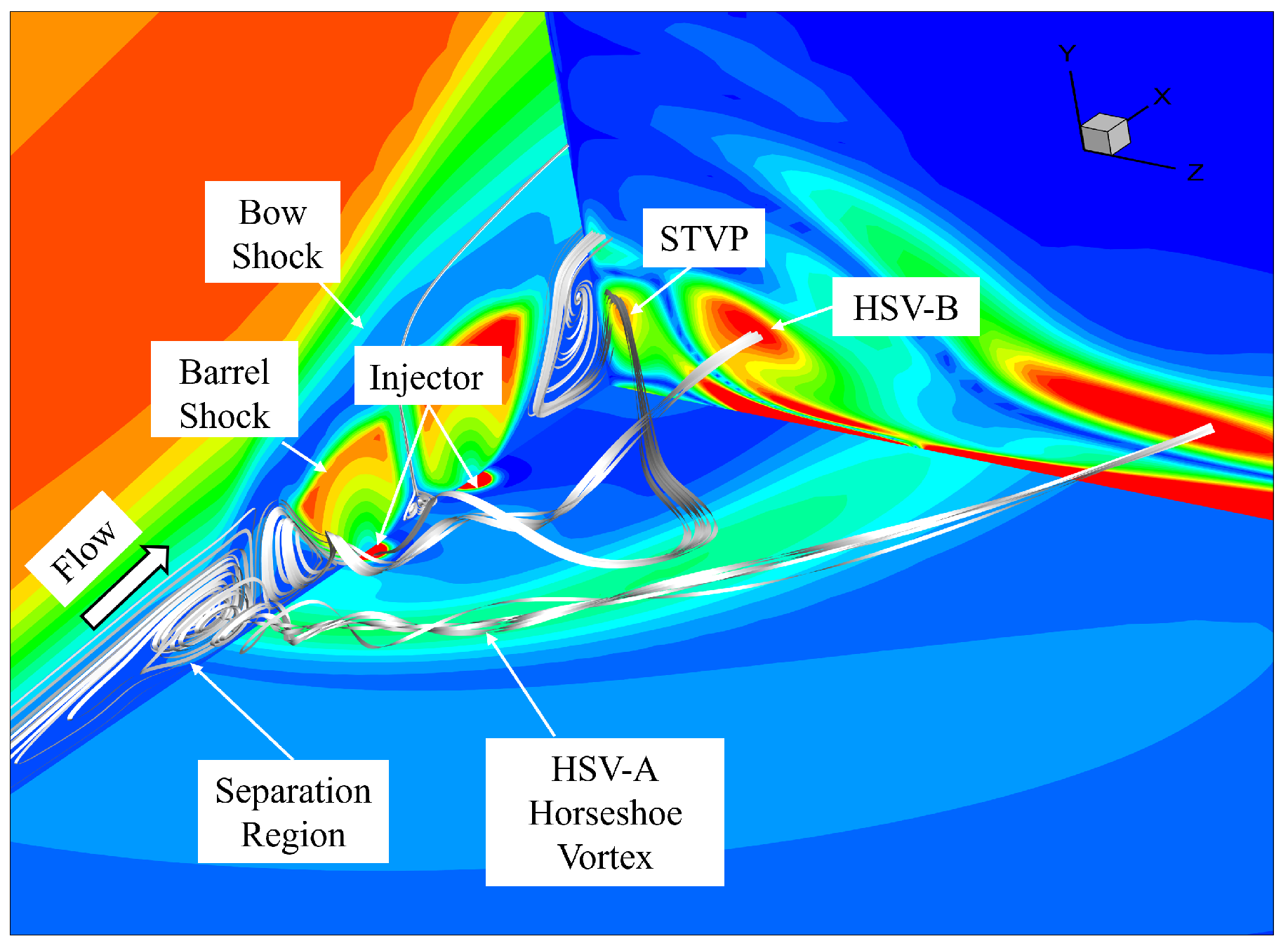
Given the pronounced three-dimensional complexity of the twin-jet flowfield, Figure 5 is used to further illustrate the flowfield features and vortex evolution using the wall static pressure distribution in the X–Z plane, the absolute streamwise vorticity distribution in the Y–Z plane, and the Mach number distribution in the X–Y plane. The adverse pressure gradient induced by the separation shock causes the boundary-layer separation region to extend across the spanwise direction. As fluid in Recirculation-A is transported outward and flows around the jet column, the first vortex structure, denoted as HSV-A, is generated. During its development, the initially spanwise vortex axis of HSV-A is stretched by the crossflow and gradually bends downstream to become parallel to the freestream, while its strength rapidly decays because the viscous shear driving its rotation is no longer perpendicular to the vortex axis. Meanwhile, Recirculation-B, located between Recirculation-A and the jet plume, is strongly entrained by the rapidly expanding plume boundary and evolves into a large-scale upward-moving counter-rotating vortex, denoted as HSV-B. HSV-A and HSV-B exhibit similar spatial distributions and are both entrained by the jet column and develop into a downstream spiraling structure.
In addition, a counter-rotating vortex pair is formed in the narrow inter-jet region, as shown in Figure 4. Owing to the small streamwise spacing between the injectors, the wake generated by the upstream jet interacts directly with the downstream jet before it can fully develop. The low-pressure wake behind the upstream jet and the high-pressure stagnation region ahead of the downstream jet establish a strong adverse pressure gradient across the inter-jet gap, which induces local flow reversal. The reversed flow then interacts strongly with the downstream-moving flow in the upstream wake shear layer, and the resulting shear and viscous entrainment lead to the formation of the inter-jet counter-rotating vortex pair.
Further downstream, blockage by the twin-jet columns creates a pronounced momentum deficit region in the wake, accompanied by a low-pressure zone that governs the formation of the surface trailing vortex pair (STVP) [31]. Part of the freestream between HSV-A and HSV-B is forced to turn inward around the jet columns and is entrained into the region directly behind the jets. The fluids entrained from both sides converge near the symmetry plane, forming the local high-pressure stagnation point shown in Figure 4. This stagnation point drives the flow downward onto the wall, rolls up the near-wall fluid, and ultimately produces the STVP system together with a stable closed recirculation bubble. By comparison, the wake structure of the single-jet configuration follows the more classical sequence of separation, bypassing, and reattachment. In the twin-jet configuration, however, the downstream jet is injected directly into the low-momentum and highly disturbed wake channel generated by the upstream jet. The interaction between the wake and the jet is therefore much stronger, causing the downstream jet plume to merge with the upstream vortex structures farther upstream. As a result, the wake vortex system in the twin-jet flowfield forms earlier, extends farther downstream, and exhibits stronger interaction.

3.2. Flowfield Characteristics Under Symmetric Jet Pressure Conditions

To establish a baseline for the asymmetric cases discussed below, Cases 6, 10, and 16 are first compared under equal upstream and downstream jet pressures. In these cases, both injectors operate at identical supply conditions, and the variation in the flowfield is therefore primarily associated with the increase in overall jet strength.
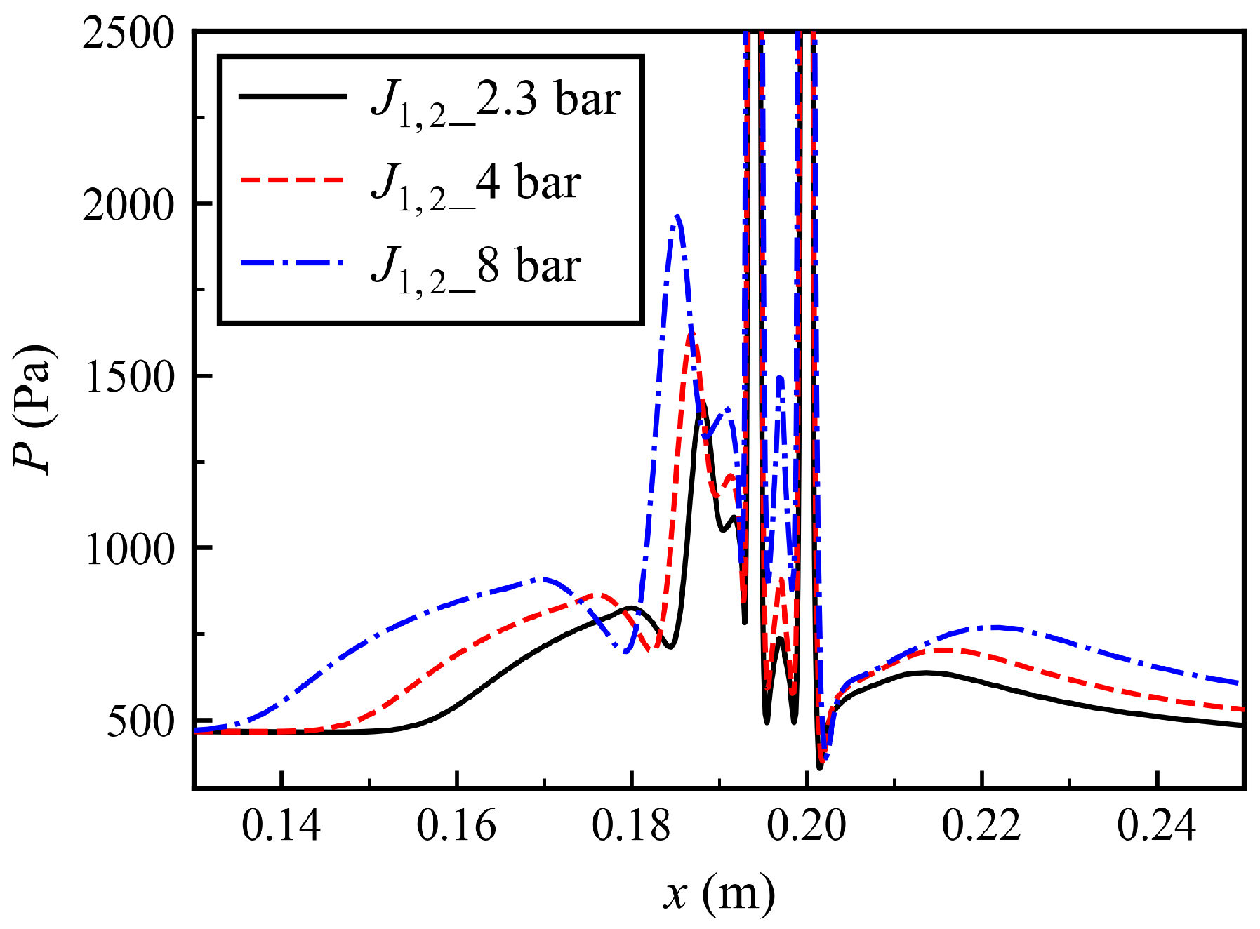
Figure 6 shows the streamwise wall static pressure distribution for Cases 6, 10, and 16, in which the two jets are operated at equal mass flow rates while the jet total pressure is progressively increased. It can be observed that both the upstream and downstream regions of the flat plate exhibit a clear pressure response as the jet total pressure increases. Upstream of the injectors, the stronger jet blockage produces a stronger adverse pressure gradient near the wall, driving the onset of the separation shock markedly upstream. When the jet total pressure increases from 4.6 bar to 16 bar, the separation region shifts upstream by approximately 20 mm, while the upstream pressure peak rises from 1420 Pa to 1960 Pa. In the region between the two injectors, increasing the jet strength intensifies the local jet–jet interaction and recirculating flow, accompanied by an increase in static pressure from 735 Pa to 1492 Pa. By contrast, the downstream wake exhibits a lower pressure level and a slower recovery process. As the jet total pressure increases, the recirculation region expands, the reattachment point shifts downstream, and the momentum deficit region behind the jets becomes larger, thereby delaying downstream pressure recovery.
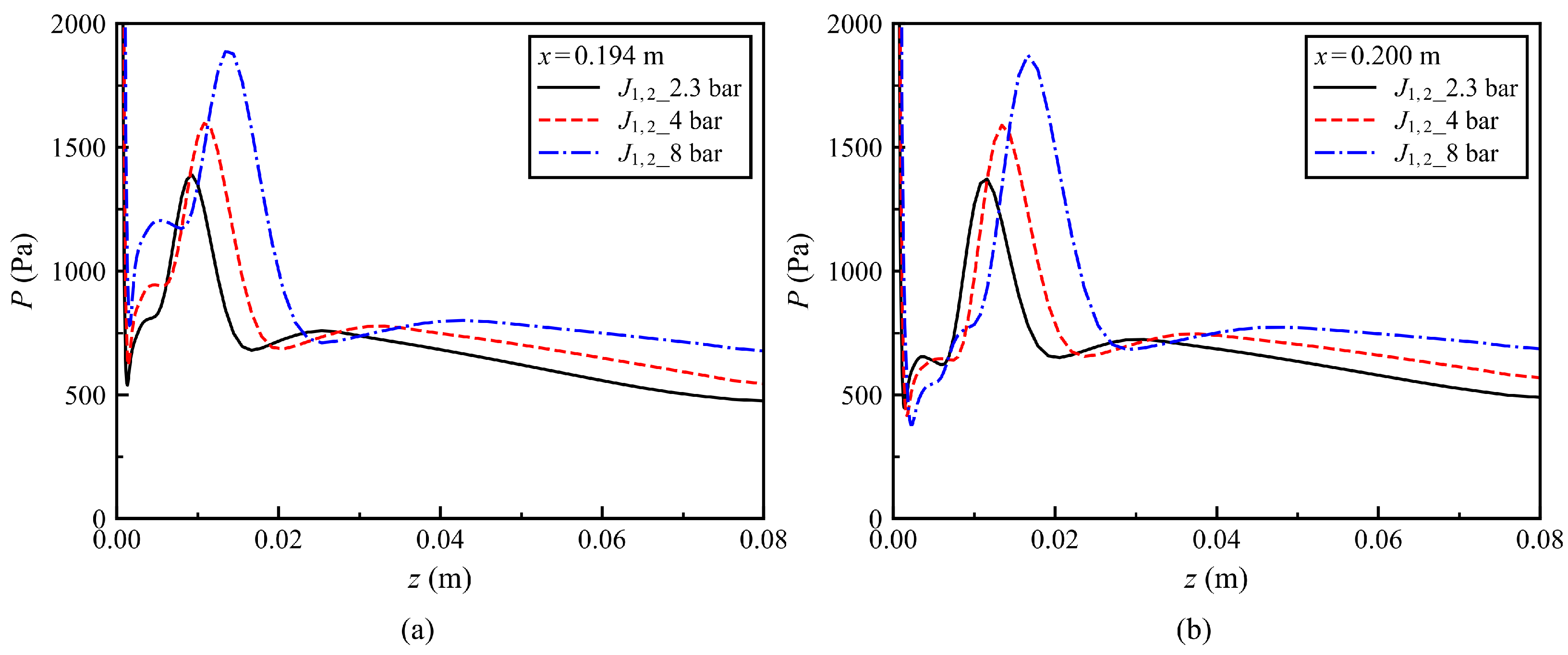
The corresponding spanwise pressure distributions through the upstream and downstream injector centerlines are shown in Figure 7. At both locations, the jet expands rapidly after issuing from the orifice, causing a sharp drop near the injector center. At the same time, the strong blockage effect imposed by the jet on the supersonic freestream generates a highly three-dimensional bow shock. The projection of this shock surface onto the wall forms a compression band with a finite spanwise width. As the flow passes through this compression band, the pressure rises again, producing the secondary peak in the spanwise profile. Farther away from the injector, the pressure gradually decreases and becomes nearly uniform. In addition, as the twin-jet strength increases, this secondary peak shifts outward in the spanwise direction. When the jet total pressure increases from 4.6 bar (Case 6) to 16 bar (Case 16), the peak position moves outward by approximately 4 mm, further indicating that the bow shock undergoes a stronger three-dimensional expansion as the jet pressure increases.
A further comparison between Figure 7a,b shows that the local minimum pressure near the injector edge is significantly higher for the upstream injector than for the downstream injector, because the upstream injector interacts directly with the freestream and generates a local high-pressure region. In addition, the characteristic changes in spanwise pressure at the downstream injector occur noticeably farther away from the symmetry plane. For example, when the total pressure of the twin-jet system is increased to 16 bar in Case 16, both the onset and recovery locations of the secondary pressure peak shift outward by about 3 mm, indicating a spanwise expansion trend away from the symmetry plane. This is because the bow shock induced by the upstream jet develops in a V-shaped form toward the downstream direction and both spanwise sides, as shown in Figure 5. By the time it reaches the cross section of the downstream injector, the shock-wall intersection has already expanded outward on both sides. As a result, the downstream spanwise pressure response is displaced farther outward than the upstream one.
These results indicate that, under symmetric jet pressure conditions, increasing the total jet strength systematically shifts the separation region upstream, raises the pressure level in the inter-jet region, and delays pressure recovery in the downstream wake. Meanwhile, certain differences have already emerged between the upstream and downstream injectors in terms of local pressure distribution and shock structure evolution. These baseline features provide a reference for the following analysis of asymmetric jet interaction.

3.3. Upstream Flowfield Response to Downstream Jet Enhancement

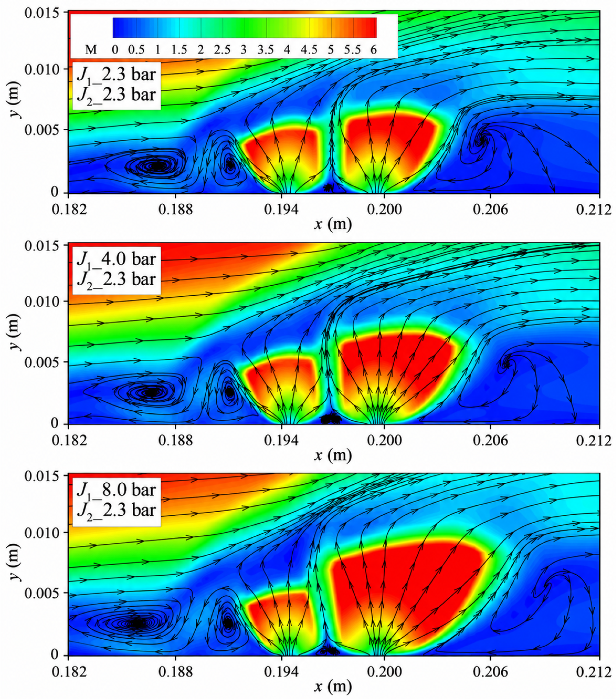
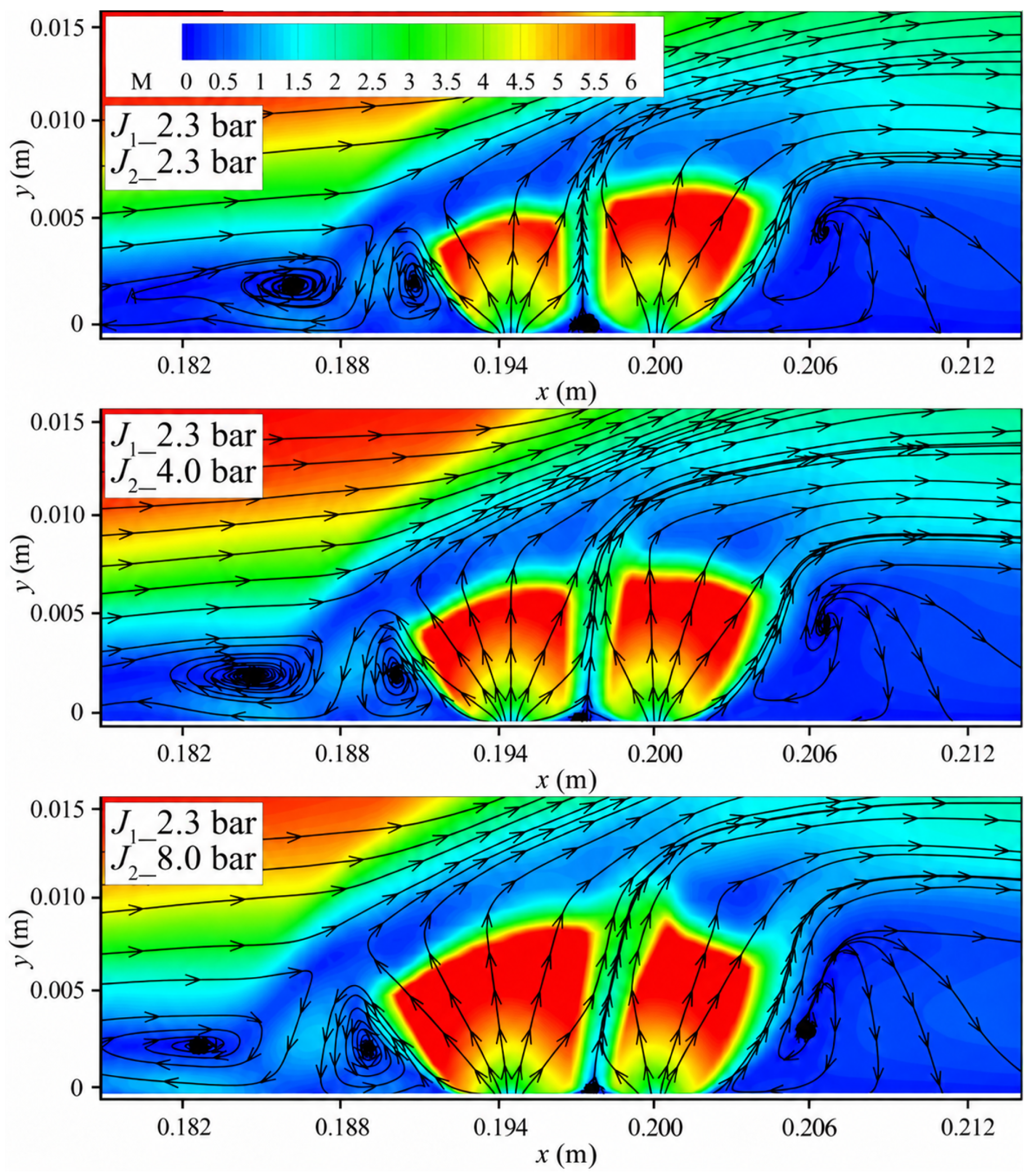
The downstream-to-upstream influence is examined using Cases 6, 9, and 15, for which the upstream jet total pressure is fixed at P 0 , j 2 = 2.3 bar , while the downstream jet pressure is progressively increased. As shown in Figure 8, strengthening the downstream jet increases its degree of underexpansion, enlarges the Mach disk, and increases the penetration height. At the same time, the downstream jet induces a stronger adverse pressure gradient near the wall, driving the upstream separation shock system upstream as a whole.
This influence is further quantified from several aspects, as summarized in Table 3. Here, x sep denotes the location of the upstream separation point, and x reatt denotes the location of the downstream reattachment point. The separation and reattachment locations are determined using the wall skin-friction coefficient [32]. As indicated by the tabulated data, the upstream separation point moves markedly upstream as the downstream jet total pressure increases, while the wake reattachment point behind the downstream injector shifts noticeably downstream. These results suggest that strengthening the downstream jet not only enlarges the upstream separation region, but also modifies the downstream wake and recirculation region.
However, this upstream influence is manifested mainly in the variation in the separation-region scale, while its effect on the geometric shape of the separation shock itself remains relatively weak. In Table 3, β sep denotes the approximate angle of the upstream separation shock. To reduce the influence of the near-wall viscous sublayer and the local strong compression region, six horizontal streamwise pressure characteristic lines were extracted at equal intervals in the symmetry plane over the height range from y = 0.005 m to y = 0.01 m . By identifying the onset of the pressure rise induced by the separation shock at each height and performing linear fitting, the approximate inclination angle of the separation shock under each condition was obtained. The fitted separation shock angles under different conditions differ only slightly, indicating that the increase in downstream jet total pressure mainly changes the location and extent of the separation region, while its influence on the geometric inclination of the separation shock remains limited. This trend is consistent with the results of Xue et al. [33]: the geometric characteristics of the separation shock are governed mainly by the freestream conditions and do not change significantly with increasing jet pressure.
Table 3 also lists the maximum expansion Mach number ( M j 2 , max ) in the core region of the upstream jet, and the Mach disk height ( H j 2 , MD ) under different downstream jet total pressures. Although the supply condition of the upstream injector remains unchanged, both the maximum expansion Mach number and the Mach disk height of the upstream jet decrease as the downstream jet total pressure increases. These results indicate that a stronger downstream jet suppresses the free expansion of the upstream jet by modifying the local pressure environment and the distribution of compression structures in the inter-jet region. This further demonstrates the pronounced bidirectional interaction between the two jets.
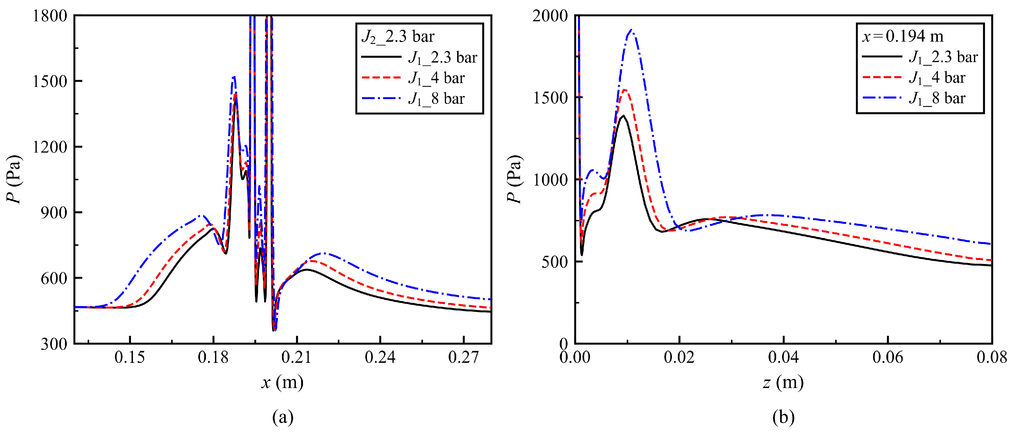
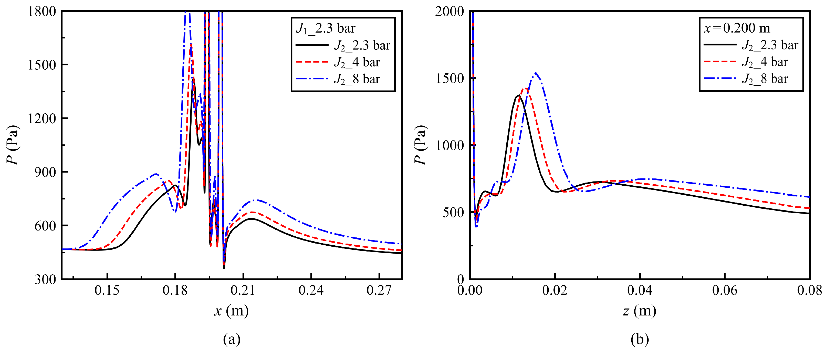
Figure 9 shows the centerline streamwise wall static pressure distribution and the spanwise wall static pressure distribution around the upstream injector for varying downstream jet total pressure with constant upstream jet total pressure. As shown in Figure 9a, as the downstream jet strengthens, the pressure peak in the upstream separation region increases from 1420 Pa in Case 6 ( P 0 , j 1 = 2.3 bar ) to 1526 Pa in Case 15 ( P 0 , j 1 = 8 bar ), again indicating that the downstream jet exerts a pronounced upstream influence on the separation region. Meanwhile, in the inter-jet region, increasing the downstream jet pressure also induces a stronger local pressure response. When the upstream pressure is held constant and the downstream jet pressure is increased, the average wall static pressure in the inter-jet region rises significantly from 644.2 Pa to 837.1 Pa, corresponding to an increase of approximately 30%. This indicates that the aerodynamic environment in the inter-jet region is highly sensitive to the downstream jet strength. In addition, Figure 9b further shows that the stronger downstream jet transmits high-pressure disturbances upstream through the near-wall subsonic boundary layer, thereby enhancing the spanwise pressure distribution around the upstream injector. Taken together, these results indicate that the strengthening of the downstream jet not only drives the upstream separation region farther upstream through an adverse pressure gradient, but also suppresses the free expansion of the upstream jet, elevates the inter-jet pressure level, and exerts a pronounced influence on the upstream flowfield in the spanwise direction.

3.4. Downstream Flowfield Response to Upstream Jet Enhancement

The reverse coupling process is examined using Cases 6, 7, and 8, for which the downstream jet total pressure is held constant while the upstream jet pressure is progressively increased. Figure 10 shows that strengthening the upstream jet increases its blockage of the incoming crossflow and drives the primary separation region markedly upstream. As summarized in Table 3, the upstream displacement of the separation region caused by variations in the upstream jet total pressure is significantly larger than that induced by variations in the downstream jet pressure, indicating that the upstream jet still plays the dominant role in controlling the scale of the upstream separation region. In contrast, the downstream reattachment location changes only slightly as the upstream jet strength increases. This behavior suggests that the upstream jet primarily modifies the effective crossflow encountered by the downstream plume, whereas the downstream near-wall reattachment remains more strongly controlled by the local interaction generated by the downstream jet itself.
As noted in Section 3.1, the shielding effect of the upstream jet on the downstream flowfield is more clearly reflected in the core structure of the downstream jet. Because the downstream injector is located in the high-pressure region behind the upstream shock, excessive lateral expansion of the downstream jet is suppressed, causing the jet structure to become more concentrated and develop more fully in the wall-normal direction into the freestream. As shown in Table 3, both the maximum Mach number and the Mach disk height of the downstream jet increase monotonically with increasing upstream jet total pressure. By contrast, the inclination of the upstream separation shock changes only slightly as the upstream jet total pressure increases, further indicating that the upstream separation shock angle is governed mainly by the freestream conditions rather than by jet-pressure variation.
The wall static pressure distribution further reflects the asymmetric interaction mechanism between the two jets. Figure 11a shows that, as the upstream jet strength increases, the wall pressure rise associated with the leading separation shock shifts markedly upstream, while the local pressure peak in the upstream separation region increases from 1420 Pa in Case 6 ( P 0 , j 2 = 2.3 bar ) to 1933 Pa in Case 8 ( P 0 , j 2 = 8 bar ). Although the downstream reattachment location changes only slightly, the pressure recovery in the wake region becomes noticeably faster, consistent with a modification of the wake-recovery process. Meanwhile, the average wall static pressure in the inter-jet region varies only within a relatively small range of 621–697 Pa, indicating a much weaker response than that induced by variations in the downstream jet. By contrast, Figure 11b shows that the upstream jet strength has a more direct influence on the downstream spanwise pressure field. The primary bow shock induced by the upstream jet not only shifts upstream in the streamwise direction, but also expands markedly toward both spanwise sides as it develops downstream. This change in the shock structure directly causes the downstream spanwise boundary to move significantly outward, with the secondary pressure peak shifting from z = 11.6 mm in Case 6 ( P 0 , j 2 = 2.3 bar ) to z = 12.5 mm in Case 7 ( P 0 , j 2 = 4 bar ), and further to z = 15.5 mm in Case 8 ( P 0 , j 2 = 8 bar ). Meanwhile, the stronger upstream bow shock also produces a greater compression effect, leading to a higher overall spanwise pressure level downstream. Taken together, these results indicate that strengthening the upstream jet mainly modifies the effective crossflow conditions ahead of the downstream injector through shielding and shock-structure reorganization, thereby strengthening the penetration and compression effects of the downstream jet in both the streamwise and spanwise directions.

4. Aerodynamic Characteristics

The aerodynamic effect of transverse-jet control arises from both the direct reaction force of the injected gas and the additional surface loads induced by jet–crossflow interaction. In a twin-jet configuration, the redistribution of wall pressure can generate substantial additional aerodynamic forces and moments; therefore, jet thrust alone is insufficient to characterize the overall control effectiveness [34]. To quantify these effects, the interaction force, jet net thrust, total aerodynamic force, and corresponding moments are defined below [35,36,37]. Subsequently, the overall aerodynamic differences between the twin-jet and single-jet configurations are compared under the same total jet input. The effects of variations in the upstream and downstream jet total pressures on the aerodynamic response of the twin-jet system are then further investigated, thereby providing a unified evaluation of the control characteristics under different jet pressure allocations.
The aerodynamic interaction force represents the additional aerodynamic load generated on the vehicle surface by the shock-wave/boundary-layer interaction induced by the jet interaction. It is defined as follows:
F ji = ∫ ∫ S wall ( P w , j − P w , b ) d S wall
Here, the integration is performed over the entire disturbed flat-plate wall surface, where P w , j is the local wall static pressure with jet injection, P w , b is the corresponding wall static pressure without jet injection, and S wall denotes the area of the wall integration region in the half-domain.
The jet net thrust F j is determined jointly by the momentum flux and the pressure term at the jet exit, and represents the sum of the net thrust generated by the twin jets. It is calculated as follows [38]:
F j = ∑ i = 1 2 ∫ ∫ S jet , i ρ j , i v j , i 2 + P j , i − P b , i d S jet , i ,
where S jet , i denotes the total exit cross-sectional area of the twin jets, and ρ j , i and v j , i are the local fluid density and the normal velocity component at the injector exit, respectively. Where i = 1 , 2 denotes the downstream and upstream injectors, respectively. Accordingly, the total control force can be expressed as follows:
F total = F j + F ji
The total control moment M total is further introduced to characterize the moment response of the jet system about the selected reference point. In the present study, the geometric center of the downstream injector is adopted uniformly as the moment reference point, x ref = 0.2 m . This fixed reference is common to the downstream single-jet baseline and all tandem twin-jet configurations, thereby providing a consistent basis for isolating the additional moment response introduced by the upstream jet and the associated jet–jet interaction. The wall control moment is calculated as:
M ji = ∫ ∫ S wall ( P w , j − P w , b ) ( x ref − x ) d S wall
Because the center of the downstream injector is selected as the moment reference, the direct thrust of the downstream jet has zero moment arm about this point. Therefore, the direct jet-thrust contribution to the control moment arises only from the upstream injector and is expressed as follows:
M j 2 = ∫ ∫ S j 2 ( ρ j 2 v j 2 2 + P j 2 , i − P b , i ) ( x ref − x ) d S j 2
The resulting moment is therefore an actuator-centered comparative quantity rather than the absolute pitching moment of a complete vehicle about its center of gravity. Accordingly, the total control moment is expressed as follows:
M total = M ji + M j 2
In these equations, x is the streamwise coordinate of the wall surface element, and P j 2 denotes the pressure at the center of the upstream injector. When ( x ref − x ) > 0 (i.e., x < 0.2 m ), a positive pressure increment located upstream of the reference point produces a positive nose-down pitching moment, whereas a positive pressure increment located downstream of the reference point produces a negative moment. This definition helps isolate the moment variation and directly reflects the moment arm effect of the jet location and the disturbed flowfield relative to the fixed reference point.
Based on the above definitions of force and moment, the effective moment arm x eff is introduced to characterize the distance between the line of action of the resultant force and the reference point. Since only the magnitude of this distance is considered here, the absolute value is taken to eliminate the influence of the sign convention for force and moment. Therefore, a larger x eff indicates that the resultant force acts farther from the reference point. Its definition is given as follows:
x eff = M total F total
To quantify the influence of the mutual interaction between the twin jets on the aerodynamic characteristics of the hypersonic vehicle, the interaction force amplification factor K F is introduced. Its definition is given as follows:
K F = F j + F ji F j = 1 + F ji F j
In addition, to eliminate the influence of differences in freestream scale and jet strength under different conditions, the force and moment are further nondimensionalized. The control force coefficient and the total moment coefficient are defined as follows:
C F ji = F ji q ∞ S ref
C M , total = M total q ∞ S ref L ref ,
here, q ∞ is the freestream dynamic pressure, S ref is the reference area of the flat plate, and L ref is the reference length from the leading edge of the flat plate to the downstream jet orifice, which is 0.2 m .

4.1. Comparison of Aerodynamic Characteristics Between Single and Twin-Jet Configurations

The influence of jet allocation on the integrated aerodynamic response is first examined using Cases 2, 3, 10, 12, 13, and 14, for which the combined jet total pressure is maintained at P 0 , j 1 + P 0 , j 2 = 8 bar . Because the two injectors have identical exit areas, jet species, temperatures, and sonic-exit conditions, these cases correspond to essentially matched total jet mass flow rate and net thrust, while the allocation between the upstream and downstream injectors is varied.
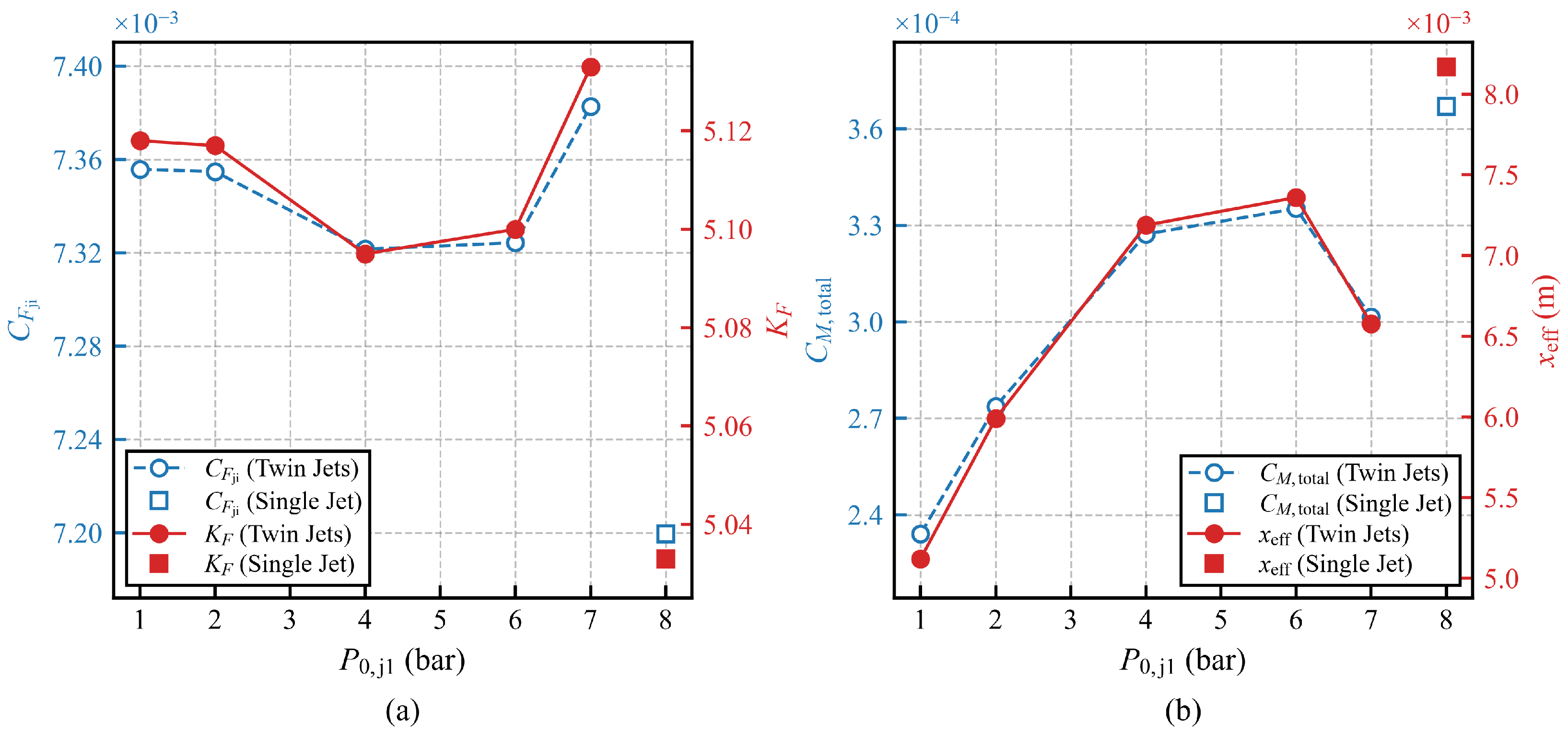
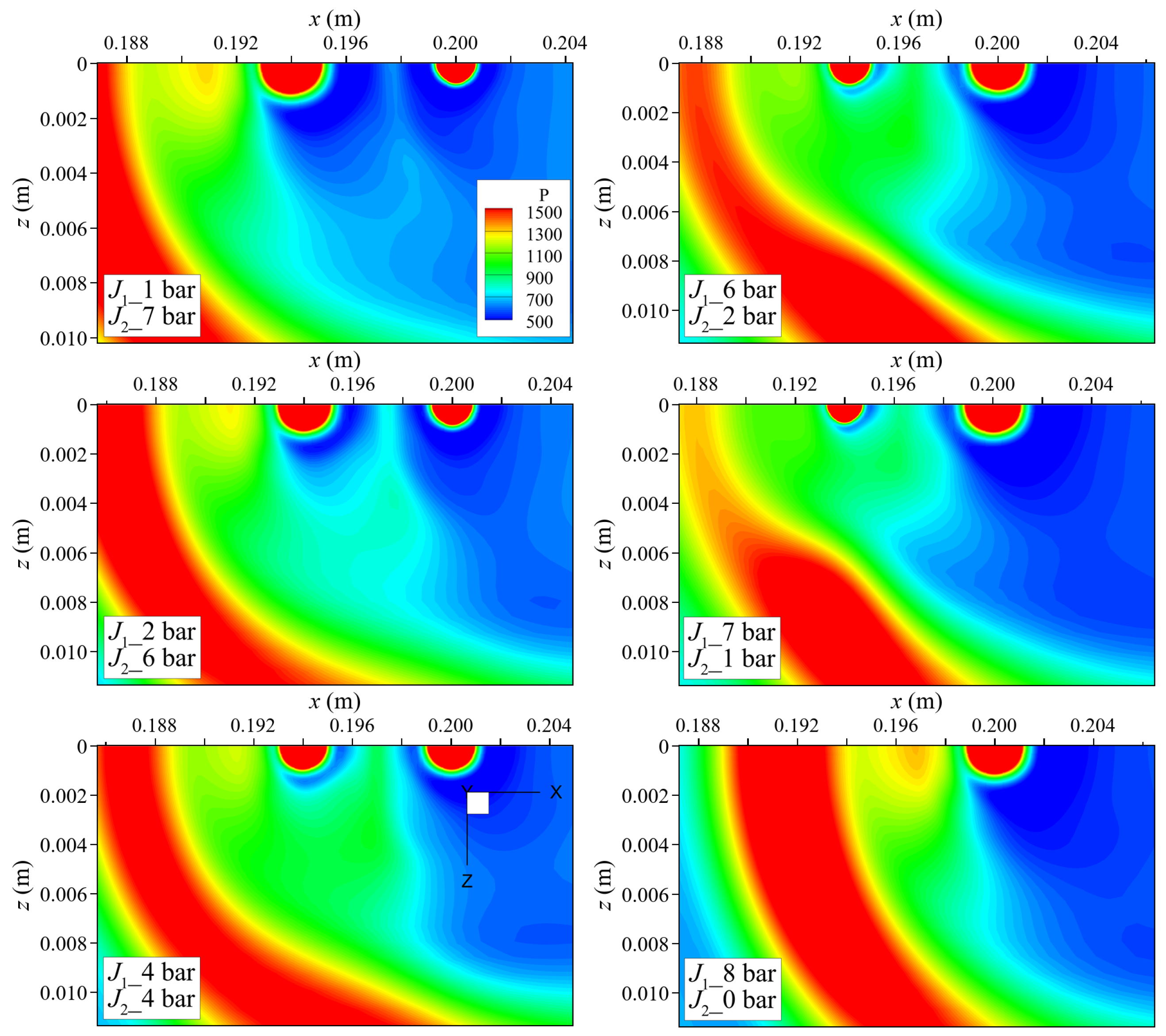
As shown in Figure 12a, all twin-jet allocation cases exhibit higher C F ji than the downstream single-jet Case 14. The corresponding force amplification factor K F follows the same trend because the total jet net thrust remains nearly unchanged among these cases. The difference arises primarily from the redistribution of the wall-pressure field. As shown in Figure 13, when the total jet supply is discharged through the downstream injector alone, a concentrated compression region and a relatively high wall-pressure peak form upstream of the injector. In the twin-jet configurations, the upstream jet displaces the incoming boundary layer and modifies the local flow approaching the downstream injector through aerodynamic shielding. Consequently, the pressure rise induced by the two jets is redistributed over a broader wall region, although the local peak pressure does not necessarily exceed that of the single-jet case. Because F ji is determined by the surface integral of the wall-pressure increment, the larger spatial extent of the positive pressure disturbance produces a greater integral control force and hence a higher C F ji . For the cases considered, the combined jet total pressure and the remaining exit conditions are identical, resulting in approximately comparable total jet net thrusts. Therefore, K F exhibits a variation consistent with that of C F ji .
However, C M , total does not follow the same trend as C F ji and K F . As shown in Figure 12b, the twin-jet cases generally exhibit lower total moment coefficients than the downstream single-jet case. Because the moment is evaluated about the center of the downstream injector, its magnitude depends not only on the integrated aerodynamic force but also on the spatial distribution of the wall-pressure increment relative to this reference point. In the twin-jet configurations, the interaction between the two jets redistributes the pressure disturbance over a broader wall region and shifts the effective center of pressure closer to the reference point. In addition, pressure disturbances located on opposite sides of the reference point produce moments of opposite signs, resulting in partial moment cancellation. Consequently, although the twin-jet configurations produce a larger integrated control force, their smaller effective moment arm leads to a lower C M , total . This interpretation is consistent with the effective-moment-arm results shown in Figure 12. Therefore, for the jet-pressure-allocation cases examined here, the total moment coefficient of the twin-jet configuration remains lower than that of the downstream single-jet configuration.

4.2. Aerodynamic Characteristics Response to Upstream and Downstream Jet Pressure Variations

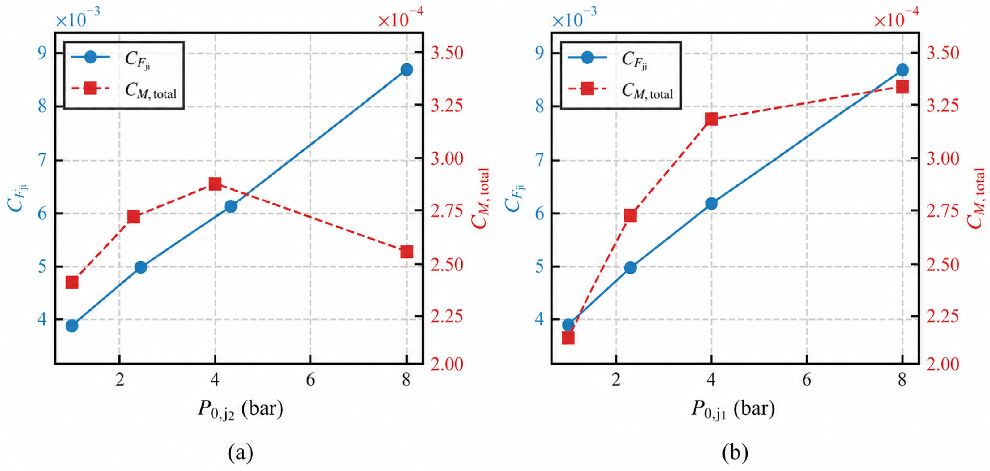
Based on the baseline comparison above, this section further examines how the aerodynamic response evolves when each jet is varied independently while that of the other injector is kept constant. Figure 14 shows the variations of the control force coefficient C F ji and the total moment coefficient C M , total of the twin-jet configuration under conditions of varying upstream jet total pressure (Cases 5, 6, 7, and 8) and varying downstream jet total pressure (Cases 1, 6, 9, and 15), respectively. It can be seen that, regardless of whether the upstream or downstream jet total pressure is increased individually, C F ji exhibits a pronounced monotonic increase with increasing jet strength. This monotonic increase is primarily associated with the stronger jet-induced blockage and the resulting expansion of the wall-pressure disturbance. As the jet pressure increases, the wall-normal penetration momentum of the jet fluid is significantly enhanced, inducing a stronger three-dimensional bow shock ahead of the jet. The resulting adverse pressure gradient near the wall drives the separation region ahead of the injector to expand in both the streamwise and spanwise directions, thereby enlarging the interaction region between the jet and the freestream and continuously increasing C F ji .
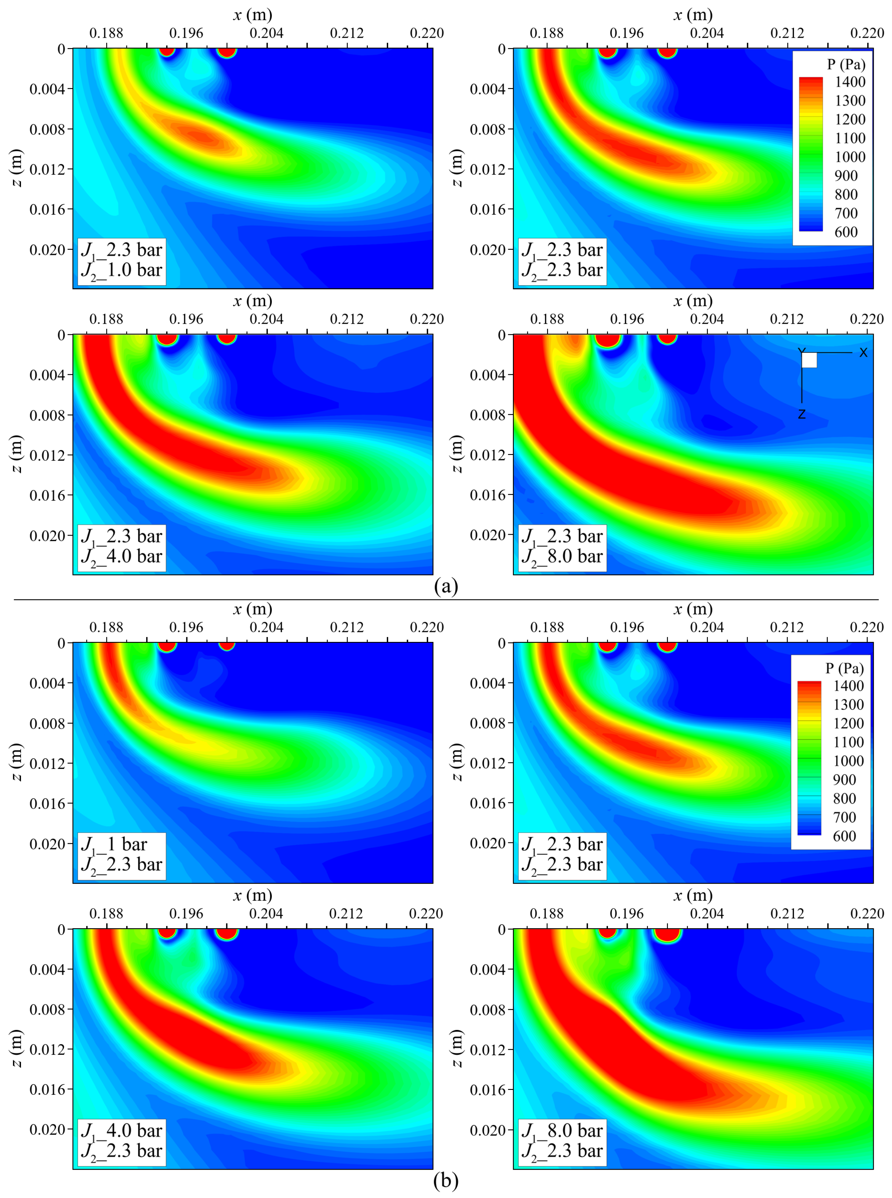
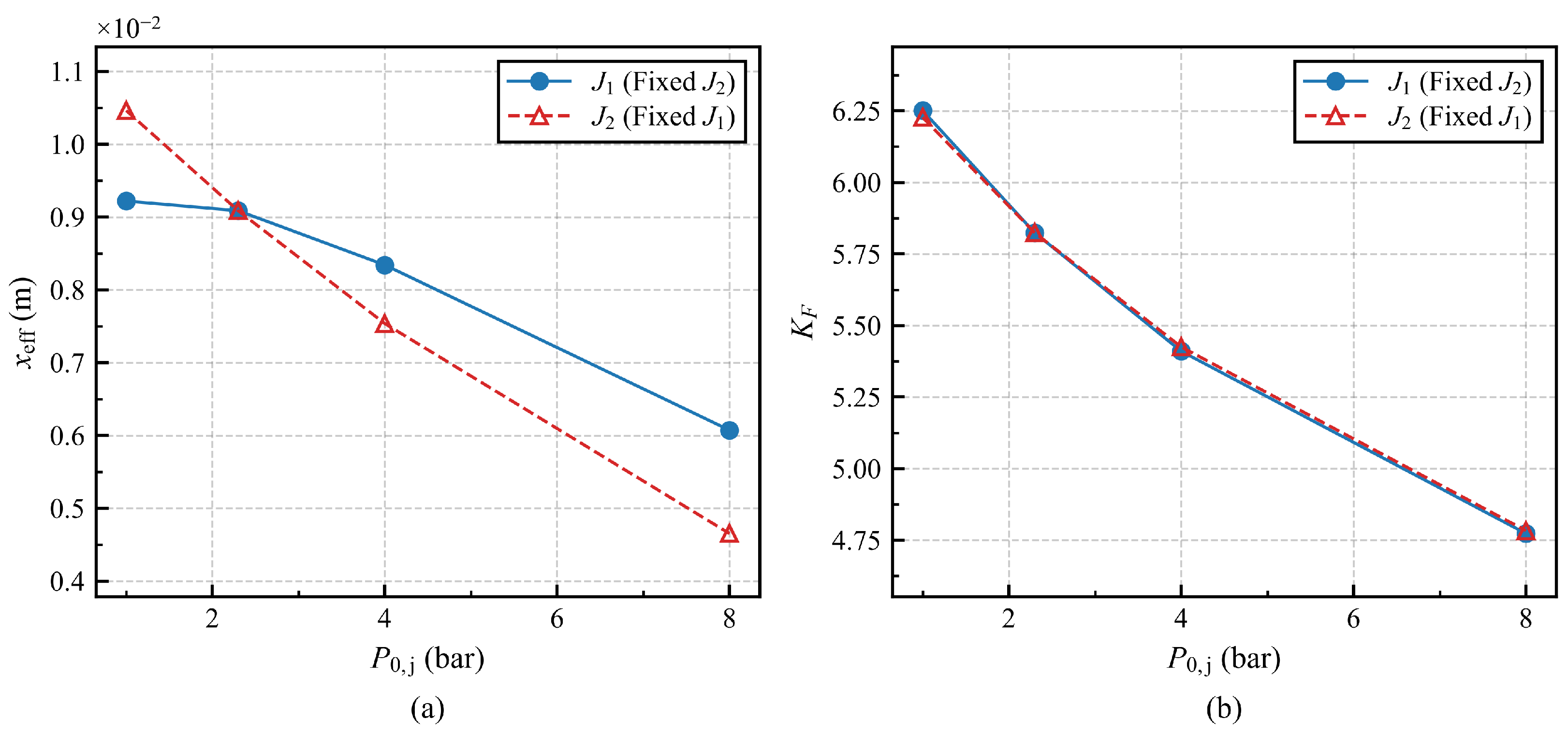
In contrast to the monotonic variation in C F ji , the total control moment coefficient C M , total , referenced to the injector center at x = 0.2 m , exhibits a pronounced asymmetric behavior. As shown in Figure 14a, when the strength of the upstream jet increases, C M , total reaches a peak at an upstream jet total pressure of about 4 bar and then decreases. Figure 15a further shows that the effective moment arm continuously decreases and gradually approaches the reference point. The pressure contours near the injector in Figure 16a suggest that this nonmonotonic behavior is associated with the evolution of the wall static pressure distribution relative to the reference point. At relatively low upstream jet pressures, the high-pressure region associated with the upstream jet–crossflow interaction remains concentrated mainly upstream of the reference point, causing the total moment magnitude to increase. As the upstream jet is further strengthened, however, the high-pressure region extends progressively downstream, while the shielding effect simultaneously accelerates pressure recovery in the downstream wake. These two effects intensify the moment cancellation between the upstream and downstream regions. As a result, C M , total exhibits a nonmonotonic variation, first increasing and then decreasing.
A further comparison between Figure 14a,b shows that strengthening the downstream jet produces a much larger increase in moment than strengthening the upstream jet. This phenomenon is consistent with the interaction mechanism discussed above, mainly because the enhancement of the downstream jet acts directly on the downstream wake region, weakening the pressure recovery there while simultaneously increasing the static pressure in the inter-jet region, so that the negative moment is weakened while the positive moment is strengthened. Figure 15a further shows that the variation in the effective moment arm under downstream jet enhancement is much slower than that under upstream jet enhancement. Therefore, the downstream jet pressure has a more significant influence on the total moment.
Turning to the control-force amplification factor, Figure 15b shows that, over the parameter ranges examined, K F decreases monotonically as either the upstream or downstream jet total pressure is increased. According to Equation (14), this trend indicates that the jet net thrust F j increases more rapidly than the control force F ji . As the jet total pressure continues to increase, the jet net thrust increases more rapidly than the wall-integrated control force. Although stronger injection enhances jet penetration, blockage, and the associated pressure disturbance, the wall-pressure load does not increase proportionally with F j . Consequently, F ji / F j decreases with increasing jet strength, resulting in the monotonic reduction in K F .

5. Conclusions

This study investigates the flow characteristics of twin transverse jets under low-density hypersonic freestream conditions, with emphasis on the flowfield structural features, the mutual interaction between the upstream and downstream jets, and the resulting aerodynamic characteristics. The results show that the twin-jet flow is not a simple superposition of two single jets. Instead, the interaction between the two jets gives rise to new separation, compression, and wake development behaviors near the wall. Compared with the single-jet configuration, the twin-jet configuration shifts the upstream separation region farther upstream and enlarges the overall interaction region, indicating a stronger global jet–crossflow interaction.
Further results show that the mutual influence between the two jets is distinctly directional and asymmetric. Strengthening the upstream jet mainly modifies the effective local crossflow conditions ahead of the downstream injector, thereby enhancing downstream jet penetration and promoting wake development. By contrast, strengthening the downstream jet exerts a stronger influence on the upstream separation system through the near-wall pressure field, suppresses the free expansion of the upstream jet, and intensifies the compression and recirculation structures in the inter-jet and near-wake regions. Thus, within the twin-jet system, the upstream jet primarily reshapes the downstream local crossflow conditions, whereas the downstream jet has a stronger influence on the upstream separation response.
In terms of the overall aerodynamic characteristics, the control force coefficient C F ji increases with jet strength, whereas the control force amplification factor K F decreases continuously. This indicates that the growth of additional control force gradually lags behind the increase in jet net thrust as the jet becomes stronger. Under the same total jet input, the twin-jet configuration generally produces a higher K F than the corresponding single-jet configuration, indicating a stronger aerodynamic gain. The total control moment coefficient C M , total , however, shows a different sensitivity: it is more strongly affected by the downstream flow-rate allocation, and strengthening the downstream jet yields a larger moment-control gain than strengthening the upstream jet. At the same time, the twin-jet configuration produces a lower total control moment about the selected reference point, indicating that jet allocation can be used to modify the force-moment balance of the system.
Overall, for a given total jet input, the twin-jet configuration generates a larger control force than the single-jet configuration while also producing a more favorable wall static pressure distribution. More importantly, differential allocation of the upstream and downstream jet flow rates provides an effective means of tuning both the flowfield structure and the aerodynamic force and moment response. These results provide a physical basis for injector arrangement and jet-strength allocation in multi-jet direct force control systems under low-density hypersonic conditions. It should be noted that the present study is confined to a twin-jet configuration with nitrogen as the jet medium and a fixed injector spacing of 6 mm . Although the current results provide useful insight into the underlying flow characteristics, further investigations are still required for more complex engineering applications. In particular, the effects of different jet media and injector spacings on the flowfield evolution, aerodynamic performance, and optimal design should be systematically examined in future work.


Author Contributions

Conceptualization, B.H. and K.L.; methodology, B.H. and K.L.; software, B.H.; validation, B.H., Q.W. and J.L.; formal analysis, B.H.; investigation, B.H.; data curation, B.H.; visualization, B.H.; supervision, K.L.; project administration, K.L.; writing—original draft preparation, B.H.; writing—review and editing, K.L., Q.W., J.L., J.Y. and W.Z. All authors have read and agreed to the published version of the manuscript.
Funding

This research was funded by the National Natural Science Foundation of China, grant numbers 12402331, 12072352, and 12232018; the Strategic Priority Research Program of the Chinese Academy of Sciences, grant number XDB 0620203; and the Youth Innovation Promotion Association of the Chinese Academy of Sciences, grant number 2021020.

Institutional Review Board Statement

Not applicable.

Informed Consent Statement

Not applicable.

Data Availability Statement

The data that support the findings of this study are available from the corresponding author upon reasonable request.

Conflicts of Interest

The authors declare no conflicts of interest.

References

  1. Xu, B.; Shi, Z. An overview on flight dynamics and control approaches for hypersonic vehicles. Sci. China Inf. Sci. 2015, 58, 1–19. [Google Scholar] [CrossRef] [Scilit]
  2. Karagozian, A.R. Transverse jets and their control. Prog. Energy Combust. Sci. 2010, 36, 531–553. [Google Scholar] [CrossRef] [Scilit]
  3. Mahesh, K. The interaction of jets with crossflow. Annu. Rev. Fluid Mech. 2013, 45, 379–407. [Google Scholar] [CrossRef] [Scilit]
  4. Pizzaia, A.; Rossmann, T. Effect of boundary layer thickness on transverse sonic jet mixing in a supersonic turbulent crossflow. Phys. Fluids 2018, 30, 115104. [Google Scholar] [CrossRef] [Scilit]
  5. Papamoschou, D.; Hubbard, D.G. Visual observations of supersonic transverse jets. Exp. Fluids 1993, 14, 468–476. [Google Scholar] [CrossRef] [Scilit]
  6. Viti, V.; Neel, R.; Schetz, J.A. Detailed flow physics of the supersonic jet interaction flow field. Phys. Fluids 2009, 21, 046101. [Google Scholar] [CrossRef] [Scilit]
  7. Zhang, Z.; McCreton, S.F.; Awasthi, M.; Wills, A.O.; Moreau, D.J.; Doolan, C.J. The flow features of transverse jets in supersonic crossflow. Aerosp. Sci. Technol. 2021, 118, 107058. [Google Scholar] [CrossRef] [Scilit]
  8. Sun, M.; Hu, Z. Formation of surface trailing counter-rotating vortex pairs downstream of a sonic jet in a supersonic cross-flow. J. Fluid Mech. 2018, 850, 551–583. [Google Scholar] [CrossRef] [Scilit]
  9. Xiao, Y.; Zhang, H.; Chen, Z.; Zhang, H.; Zheng, C. Numerical investigation on the transverse jet into a supersonic crossflow with different pressure ratios. Eng. Appl. Comput. Fluid Mech. 2024, 18, 2354760. [Google Scholar] [CrossRef] [Scilit]
  10. DeSpirito, J. Transient lateral jet interaction effects on a generic fin-stabilized projectile. In Proceedings of the 30th AIAA Applied Aerodynamics Conference, New Orleans, LA, USA, 25–28 June 2012; pp. 1060–1078. [Google Scholar]
  11. Rowton, H.C.; Medwell, P.R.; Chin, R. The mechanism behind jet entrainment into the upstream boundary layer for multi-regime mixing of a jet in hypersonic crossflow. Phys. Fluids 2025, 37, 015176. [Google Scholar] [CrossRef] [Scilit]
  12. Xie, Z.; Liu, C.y.; Meng, Y.s.; Huang, W.; Liang, Y.j.; Zhao, Z.t. Study on the aerodynamic drag similarity criterion for complex interference flow fields induced by the jet in hypersonic flow. Int. Commun. Heat Mass Transf. 2025, 165, 109060. [Google Scholar] [CrossRef] [Scilit]
  13. Zhou, Y.; Luo, Z.; Liu, Q.; Zhou, Y.; Xie, W. Effect of rudder efficiency of high-speed aircraft subject to high-energy jet. Phys. Fluids 2024, 36, 125137. [Google Scholar] [CrossRef] [Scilit]
  14. Shi, Y.; Cheng, Q.; Alizadeh, A.; Yan, H.; Choubey, G.; Fallah, K.; Shamsborhan, M. Influence of lateral single jets for thermal protection of reentry nose cone with multi-row disk spike at hypersonic flow: Computational study. Sci. Rep. 2023, 13, 6549. [Google Scholar] [CrossRef] [Scilit] [PubMed]
  15. Zhang, H.; Xiao, Y.; He, K.; Lyu, K.; Chen, Z.; Zheng, C. The 3D flow characteristics of a sonic transverse jet in laminar supersonic crossflow. Aerosp. Sci. Technol. 2025, 167, 110661. [Google Scholar] [CrossRef] [Scilit]
  16. Huang, W.; Yan, L. Progress in research on mixing techniques for transverse injection flow fields in supersonic crossflows. J. Zhejiang Univ. Sci. A 2013, 14, 554–564. [Google Scholar] [CrossRef] [Scilit]
  17. Pudsey, A.S.; Boyce, R.R. Numerical investigation of transverse jets through multiport injector arrays in a supersonic crossflow. J. Propul. Power 2010, 26, 1225–1236. [Google Scholar] [CrossRef] [Scilit]
  18. Lee, S.H. Characteristics of dual transverse injection in scramjet combustor, Part 1: Mixing. J. Propul. Power 2006, 22, 1012–1019. [Google Scholar] [CrossRef] [Scilit]
  19. Pudsey, A.S.; Wheatley, V.; Boyce, R.R. Behavior of multiple-jet interactions in a hypersonic boundary layer. J. Propul. Power 2015, 31, 144–155. [Google Scholar] [CrossRef] [Scilit]
  20. Radhouane, A.; Mahjoub Said, N.; Mhiri, H.; Bournot, H.; Le Palec, G. Dynamics of the flowfield generated by the interaction of twin inclined jets of variable temperatures with an oncoming crossflow. Heat Mass Transf. 2014, 50, 253–274. [Google Scholar] [CrossRef] [Scilit]
  21. Maikap, S.; Rajagopal, A.K. Flow physics of supersonic crossflow with transversely injected jets in streamwise tandem configuration. Phys. Fluids 2025, 37, 036113. [Google Scholar] [CrossRef] [Scilit]
  22. Chen, T.; Huang, H.; Chen, Y.; Wang, C. Effects and mechanisms of multiple lateral jets on aerodynamic characteristics of a hypersonic vehicle. Phys. Scr. 2025, 100, 125228. [Google Scholar] [CrossRef] [Scilit]
  23. Gad-el Hak, M. The fluid mechanics of microdevices—The Freeman Scholar Lecture. J. Fluids Eng. 1999, 121, 5–33. [Google Scholar] [CrossRef] [Scilit]
  24. Zhao, G.; Zhong, C.; Liu, S.; Chen, J.; Zhuo, C. Numerical simulation of lateral jet interaction with rarefied hypersonic flow over a two-dimensional blunt body. Phys. Fluids 2023, 35, 086107. [Google Scholar] [CrossRef] [Scilit]
  25. Zeng, S.; Yang, J.; Zhao, W.; Huang, Y.; Jiang, Z.; Chen, W. Computational study of lateral jet interaction in hypersonic thermochemical non-equilibrium flows using nonlinear coupled constitutive relations. Phys. Fluids 2023, 35, 116117. [Google Scholar] [CrossRef] [Scilit]
  26. Spalart, P.R.; Allmaras, S.R. A one-equation turbulence model for aerodynamic flows. In Proceedings of the 30th Aerospace Sciences Meeting and Exhibit, Reno, NV, USA, 6–9 January 1992. [Google Scholar]
  27. Luo, K.; Chen, X.; Wang, Y.; Wang, Q.; Yu, J.; Zhao, W. Experimental investigation of transverse jet interaction in low-density hypersonic crossflows. AIAA J. 2025, 63, 3827–3840. [Google Scholar] [CrossRef] [Scilit]
  28. Yu, J.; Li, J.; Wang, Q.; Zhang, S.; Zhang, X. Numerical and experimental study on high-speed hydrogen–oxygen combustion gas flow and aerodynamic heating characteristics. Phys. Fluids 2021, 33, 076103. [Google Scholar] [CrossRef] [Scilit]
  29. Hong, Z.; Davidson, D.F.; Hanson, R.K. An improved H2/O2 mechanism based on recent shock tube/laser absorption measurements. Combust. Flame 2011, 158, 633–644. [Google Scholar] [CrossRef] [Scilit]
  30. McBride, B.J.; Zehe, M.J.; Gordon, S. NASA Glenn Coefficients for Calculating Thermodynamic Properties of Individual Species; NASA Technical Paper NASA/TP-2002-211556; NASA Glenn Research Center: Cleveland, OH, USA, 2002.
  31. Fric, T.F.; Roshko, A. Vortical structure in the wake of a transverse jet. J. Fluid Mech. 1994, 279, 1–47. [Google Scholar] [CrossRef] [Scilit]
  32. Zhang, Z.; Li, X.; Hao, J. Analysis of large-scale spanwise motions in shock wave–turbulent boundary-layer interactions. J. Fluid Mech. 2025, 1018, A2. [Google Scholar] [CrossRef] [Scilit]
  33. Xue, L.; Schrijer, F.F.; Van Oudheusden, B.W.; Wang, C.; Shi, Z.; Cheng, K. Theoretical study on regular reflection of shock wave–boundary layer interactions. J. Fluid Mech. 2020, 899, A30. [Google Scholar] [CrossRef] [Scilit]
  34. Everett, D.E.; Woodmansee, M.A.; Dutton, J.C.; Morris, M.J. Wall pressure measurements for a sonic jet injected transversely into a supersonic crossflow. J. Propul. Power 1998, 14, 861–868. [Google Scholar] [CrossRef] [Scilit] [PubMed]
  35. Grandhi, R.K.; Roy, A. Effectiveness of a reaction control system jet in a supersonic crossflow. J. Spacecr. Rocket. 2017, 54, 883–891. [Google Scholar] [CrossRef] [Scilit]
  36. Zhuang, H.; Ding, D.; Chen, H.; Li, G.; Chen, H.; Zhang, B. Effectiveness of reaction control system in hypersonic rarefied reactive flow. J. Spacecr. Rocket. 2022, 59, 717–727. [Google Scholar] [CrossRef] [Scilit]
  37. Jia, M.L.; Chen, S.S.; Li, J.P.; Yuan, W.; Lin, B.X.; Gao, Z.H. Uncertainty and sensitivity study on lateral jet interaction for hypersonic missile. J. Spacecr. Rocket. 2024, 61, 458–472. [Google Scholar] [CrossRef] [Scilit]
  38. Sharma, V.; Eswaran, V.; Chakraborty, D. Numerical Study of Maneuverability Control in High-Speed Aero-Vehicles Using Transverse Sonic Jet Injectors. In Proceedings of the AIAA SCITECH 2024 Forum, Orlando, FL, USA, 8–12 January 2024. [Google Scholar]
Figure 1. Schematic of the computational domain for the twin-jet flat-plate configuration.
Aerospace 13 00865 g001
Figure 2. Grid-independence and experimental validation of wall static pressure distributions: (a) grid-independence study; (b) comparison between CFD and experimental results.
Aerospace 13 00865 g002
Figure 3. Comparison of wall-pressure distributions between reacting and frozen-chemistry calculations at P 0 , j = 2.3 bar .
Aerospace 13 00865 g003
Figure 4. Comparison of symmetry-plane Mach number contours with velocity streamlines between the single-jet and twin-jet configurations at the same jet total pressure.
Aerospace 13 00865 g004
Figure 5. Three-dimensional vortex structures of the twin-jet configuration.
Aerospace 13 00865 g005
Figure 6. Streamwise wall static pressure distributions in the twin-jet configuration at different jet total pressures, with equal upstream and downstream jet flow rates.
Aerospace 13 00865 g006
Figure 7. Spanwise wall static pressure distributions through the injector centerlines in the twin-jet configuration at different jet total pressures, with equal upstream and downstream jet flow rates: (a) upstream injector; (b) downstream injector.
Aerospace 13 00865 g007
Figure 8. Symmetry-plane Mach number contours with velocity streamlines for increasing downstream jet total pressure with the upstream jet total pressure held constant.
Aerospace 13 00865 g008
Figure 9. Wall static pressure distributions for varying downstream jet total pressure with constant upstream jet total pressure: (a) streamwise static pressure distribution; (b) spanwise static pressure distribution around the upstream injector.
Aerospace 13 00865 g009
Figure 10. Symmetry-plane Mach number contours with velocity streamlines for increasing upstream jet total pressure with the downstream jet total pressure held constant.
Aerospace 13 00865 g010
Figure 11. Wall static pressure distributions for varying upstream jet total pressure with constant downstream jet total pressure: (a) streamwise static pressure distribution; (b) spanwise static pressure distribution around the downstream injector.
Aerospace 13 00865 g011
Figure 12. Variations of the aerodynamic force and moment characteristics under different upstream/downstream jet total pressure allocations at fixed jet total pressure: (a) combined variations of C F ji and K F ; (b) combined variations of C M , total and x eff .
Aerospace 13 00865 g012
Figure 13. Pressure contours near the injectors under different upstream/downstream jet-pressure allocations at fixed jet total pressure.
Aerospace 13 00865 g013
Figure 14. Variations of C F ji and C M , total under two jet-pressure variation modes: (a) varying upstream jet total pressure with constant downstream jet total pressure; (b) varying downstream jet total pressure with constant upstream jet total pressure.
Aerospace 13 00865 g014
Figure 15. Variations of x eff and K F under different jet-strength conditions: (a) x eff ; (b) K F .
Aerospace 13 00865 g015
Figure 16. Pressure contours near the injectors under different jet-pressure variation modes: (a) varying upstream jet total pressure with constant downstream jet total pressure; (b) varying downstream jet total pressure with constant upstream jet total pressure.
Aerospace 13 00865 g016
Table 1. Freestream conditions and species mass fractions.
ParameterValue
u ∞ (m/s)3228
T ∞ (K)509
p ∞ (Pa)403
ρ ∞ ( kg m − 3 ) 2.16 × 10 − 3
M ∞ 6.4
Species Mass Fractions
Y H 2 O 0.3754
Y O 2 0.0135
Y H 2 0.0014
Y N 2 0.60577
Y OH 0.00024
Y H 0.0034
Y O 0.00029
Y H 2 O 2 0.0
Y HO 2 0.0
Table 2. Prescribed total conditions and corresponding nominal sonic static conditions for the two jets.
Case P 0 , j 1 (bar) P 0 , j 2 (bar) T 0 , j (K) P j 1 (bar) P j 2 (bar) T j (K)
11.02.33000.51.2250
21.07.00.53.7
32.06.01.03.2
42.30.01.20.0
52.31.01.20.5
62.32.31.21.2
72.34.01.22.1
82.38.01.24.2
94.02.32.11.2
104.04.02.12.1
114.60.02.40.0
126.02.03.21.0
137.01.03.70.5
148.00.04.20.0
158.02.34.21.2
168.08.04.24.2
Table 3. Variations of the flowfield characteristic parameters for varying upstream and downstream jet total pressures.
Downstream jet total pressure variation
Case x sep (m) x reatt (m) β sep (∘) M j 2 , max H j 2 , MD (mm)
60.16550.211815.845.7475.950
90.16210.213615.815.6895.876
150.15410.216915.675.6835.791
Upstream jet total pressure variation
Case x sep (m) x reatt (m) β sep (∘) M j 1 , max H j 1 , MD (mm)
60.16550.211815.846.3227.190
70.16000.212015.886.5957.786
80.15010.212815.996.68711.23
Disclaimer/Publisher’s Note: The statements, opinions and data contained in all publications are solely those of the individual author(s) and contributor(s) and not of MDPI and/or the editor(s). MDPI and/or the editor(s) disclaim responsibility for any injury to people or property resulting from any ideas, methods, instructions or products referred to in the content.