1. Introduction
Permanent magnet synchronous motors (PMSMs) have been widely used in industrial applications such as aircraft and electric vehicles due to their advantages of high power density, simple structure, and high efficiency [
1,
2]. However, traditional single-motor drive architectures have gradually shown limitations in addressing challenges such as driving high inertia loads, optimizing dynamic response, and energy-efficient cooperative control. In this context, dual-motor drive systems have emerged as a frontier research direction to meet the requirements of high-power industrial scenarios due to their distinct advantages in power distribution, dynamic compensation, and fault-tolerant control [
3].
As a new category of aircraft, electric helicopters have attracted considerable attention in modern aviation due to their low noise, zero emissions, and high energy efficiency [
4]. Compared with traditional fuel-powered helicopters, electric helicopters have remarkable advantages in reducing environmental pollution and improving flight efficiency [
5]. To further improve the flight performance of electric helicopters, researchers continue to explore more efficient and stable motor control technologies. In particular, some research progress has been made in the synchronized coordination control of dual-motor systems.
In the propulsion system of electric helicopters, dual-motor systems are typically employed to provide redundant power support, thereby enhancing system reliability and fault-tolerant capabilities [
6]. The dual-motor system in electric helicopters must not only achieve efficient energy transmission under normal operating conditions but also address dynamic coupling disturbances caused by load variations and aerodynamic perturbations during flight. To mitigate the effects of external disturbances and uncertainties in helicopter systems, ref. [
7] proposed a dual-loop control architecture: the inner loop ensures system stability, minimizes tracking errors, and enhances robustness against parametric uncertainties and disturbances; the outer loop guarantees optimal trajectory tracking while avoiding actuator saturation.
In current research on multi-motor synchronization control, ref. [
8] proposed a robust synchronous control system for multiple motors based on artificial potential fields and sliding mode variable structure. This system developed a cooperative control strategy for compensating dynamic parameter variations and external disturbances, achieving comprehensive optimization of angular synchronization accuracy and dynamic response robustness. In 1980, Professor Koren introduced a cross-coupled control strategy to realize synchronous coordination control of dual motors [
9,
10] designed a dual-motor synchronous optimization method based on master–slave cross-coupled synchronization control. By establishing a mathematical model of the hydraulic transmission system, this method performs adaptive interpolation fitting of model parameters according to cable storage states, and embeds an adaptive IMC-PI regulator into the synchronization control strategy. This approach achieves cooperative optimization of dynamic synchronization error compensation and anti-disturbance performance, thereby enhancing operational stability under multiple disturbance conditions. The master–slave control strategy utilizes the output speed of the master motor as the reference speed for the slave motor. Reference [
11] developed apermanent magnet synchronous motor drive system employing extended state observer-based sliding mode speed control (ESO-SMSC). Through the establishment of a dynamic motion model, this system collects data on internal parameter variations and external load disturbances. It performs adaptive compensation of control laws based on real-time disturbance estimation and embeds the extended state observer into the sliding mode control framework. This implementation achieves collaborative optimization of speed tracking errors and anti-disturbance capabilities, significantly improving dynamic response speed and steady-state accuracy under parameter mismatch and sudden load conditions. Reference [
12] proposed an enhanced extended state observer (ESO) incorporating modified nonlinear functions. Compared to conventional ESO that exhibit deficiencies in nonlinear function continuity and differentiability, this observer effectively suppresses high-frequency chattering phenomena through the introduction of piecewise smooth new-fal functions. The study explored the integration of the improved ESO with sliding mode control laws to compensate in real-time for compound disturbances caused by PMSM parameter perturbations and sudden loads. Closed-loop system stability was demonstrated via Lyapunov function construction, while observer dynamic characteristics were optimized through bandwidth tuning mechanisms. This method demonstrates significant improvements over traditional PI control in torque ripple suppression and speed tracking accuracy. Reference [
13] proposed a multiple innovation least squares method with forgetting factors to enhance the convergence speed and identification accuracy of conventional least squares algorithms, effectively suppressing the influence of interference data on identification results. The least squares algorithm is primarily employed for online identification of motor parameters. Through optimization of motor control parameters, it can significantly improve system efficiency and robustness. Reference [
14] designed a model predictive current control method for PMSMs based on data-driven recursive least squares estimation. This approach develops control strategies for dynamically adjusting stator current variations, achieving comprehensive optimization control of current tracking accuracy and torque response performance. Reference [
15] developed a linear extended state observer to enable real-time observation of current harmonics, utilizing voltage compensation to eliminate harmonic current effects in windings. Compared with hardware redundancy, software redundancy requires no additional hardware components. It enables functional substitution of faulty components through algorithmic implementations, thereby ensuring system reliability and fault-tolerant capabilities [
16,
17].
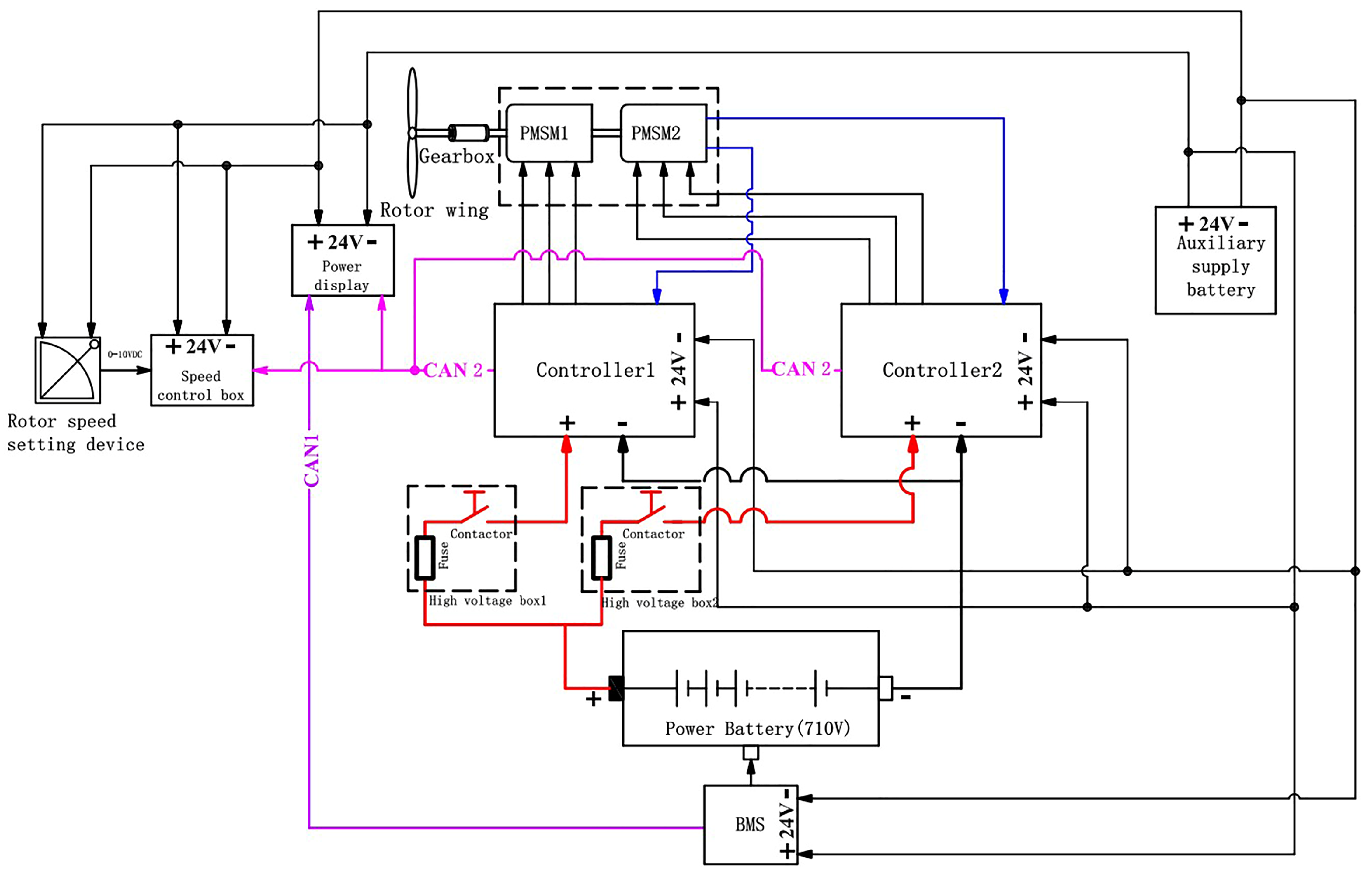
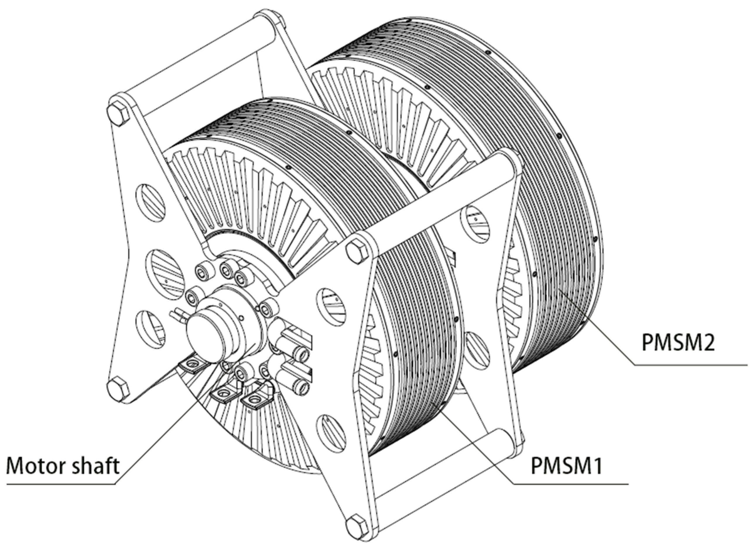
This paper proposes an improved dual-motor synchronous coordination control method to address dynamic coupling disturbance issues in electric helicopter dual-motor systems. First, a speed control loop is implemented in the master motor to set the rotor speed reference, while the auxiliary motor adopts a torque control loop. This architecture integrates an extended state observer for real-time disturbance estimation and compensation, effectively suppressing torque fluctuations. Secondly, the online identification of the motor parameters is performed using the least squares method (LSM) [
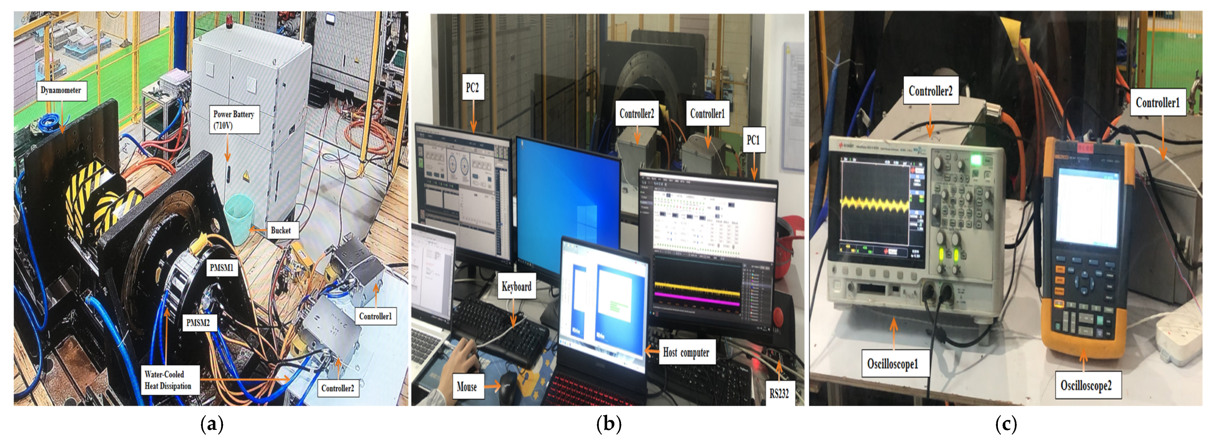
18], accompanied by the design of a torque synchronization-based control law to ensure the consistency of the output torque between the dual motors, further enhancing the system stability and efficiency. Finally, to address the flight safety of electric helicopters, experiments on dual-motor control were conducted. The results demonstrate that the proposed control method effectively enhances flight safety.
3. Dual-Motor Control Strategy Design
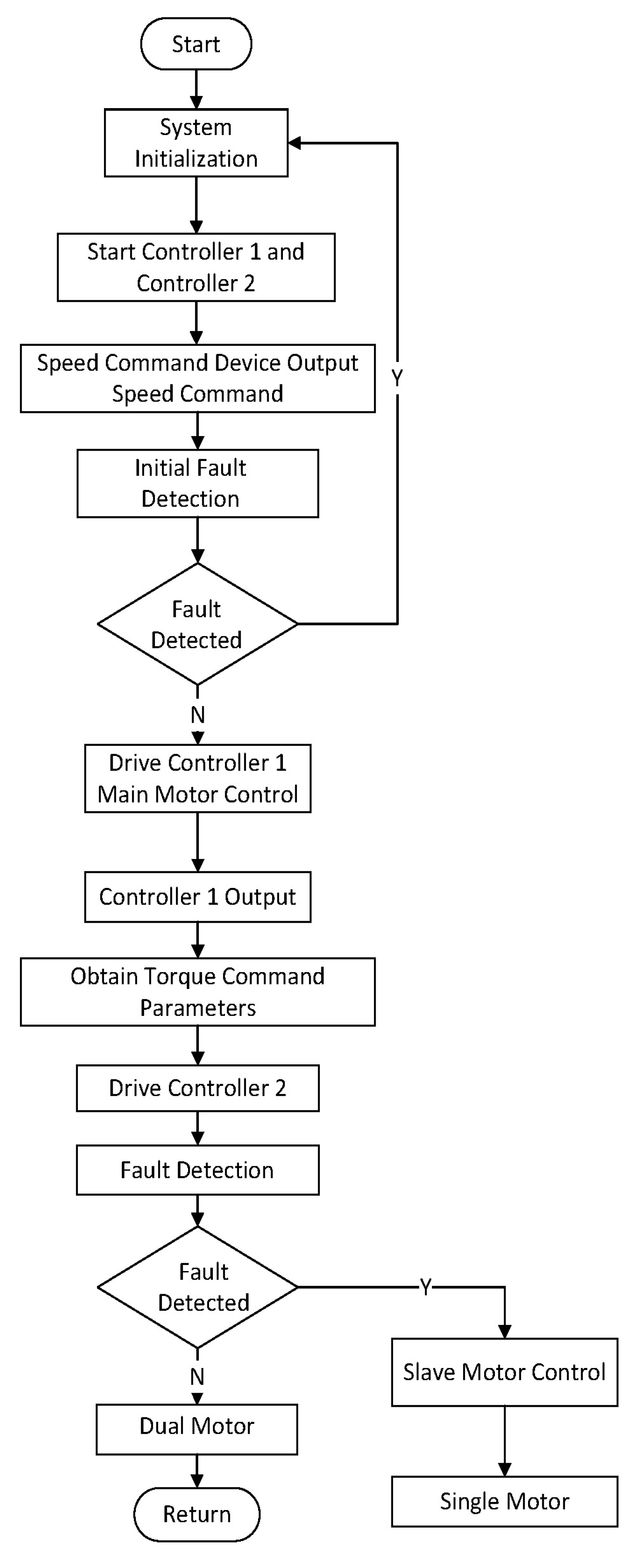
The dual-redundancy electric propulsion control system adopts a speed-torque dual-loop coordinated control architecture based on dynamic decoupling. In the torque loop design, ESO enables real-time estimation of load torque and unknown disturbances, coupled with a feedforward compensation mechanism to eliminate mechanical coupling effects between dual motors. Concurrently, a high-fidelity current-to-torque mapping model is established through least squares parameter identification, ensuring output torque consistency across both motors. The speed loop design dynamically compensates for synchronization error signals from the master–slave system using an adaptive PI controller. This architecture integrates CAN bus communication to achieve speed-independent control under fault conditions and seamless mode transition during system reconfiguration.
The master motor tracks the prescribed rotational speed
through a PI controller, generating the q-axis current reference command
.
where
denotes the speed error between the reference and feedback values,
t represents the integral time constant,
kp1 is the proportional gain, and
ki1 is the integral gain of the controller.
The parameter tuning of the PI controller in the speed outer loop can be transformed into the parameter optimization for a Type II system. By calculating the open-loop transfer function of the speed control loop and comparing it with the standard Type II system transfer function, we derive the optimal parameters of the speed loop’s open-loop transfer function corresponding to the best dynamic performance of the Type II system. This allows us to determine the proportional gain kp1 and integral gain ki1 of the PI controller.
The transfer function G(
s) can be expressed as
where
Ts is the sampling time.
The transfer function of a canonical Type II system can be expressed as
where
K is the open-loop gain,
τ is the delay time, and
T is the time constant of the system.
In a typical type II system, the IF width with a slope of −20 dB/sec is defined as h. The best PMSM dynamic following performance is achieved when the IF width h = 5. According to the principle of minimum, the peak value of the closed-loop amplitude-frequency characteristic, the values of
kp1 as well as
ki1 can be known:
In the dual-motor system, the auxiliary motor (PMSM 2) is controlled using a torque loop strategy. The aim is to ensure that the electromagnetic torque of the auxiliary motor follows the reference torque, while compensating for load disturbances and mechanical coupling effects through feedforward compensation of the estimated disturbance.
where (13) denotes the torque command,
T2e,ref denotes the reference torque and
represents the estimated disturbance (including load torque
TL and coupling effects) for external influence compensation.
According to (7), the disturbance definition
d = −
TL, the motion equation can be rewritten as
To estimate the disturbance
d, it is treated as an extended state
z =
d, with the assumption that its derivative
(where
is generally unknown). Taking the rotational speed
as the state variable, the system dynamics can be expressed as
Standard canonical formulation:
where
Augmented state-space equations:
ESO generates estimates of the state x and disturbance z, with the estimated values denoted as
and
. The ESO dynamics are governed by the following equations:
where
are observer gains.
Define the estimation error , disturbance estimation error .
If
= 0, the characteristic polynomial is the translation:
Choose the gain
,
such that the characteristic polynomial is
The characteristic roots are located at s = −ω0 (with multiplicity), ensuring the stability of the ESO and allowing its convergence rate to be regulated by adjusting ω0.
If , s = −ω0 (with multiplicity), ensuring a Hurwitz matrix.
To analyze the bounded-input bounded-output (BIBO) stability of the ESO system, we derive the transfer functions from the error dynamics Equation (25). Taking the Laplace transform of Equation (25) with ξ as input and considering zero initial conditions, we obtain the following transfer functions:
where G
e(s) is transfer function from input disturbance ξ(t) to state estimation error, G
d(s) is transfer function from input disturbance ξ(t) to disturbance estimation error.
In practical helicopter applications, external disturbances are typically bounded but persistent, ∣ξ(t)∣ ≤ Dmax, where Dmax is a known positive constant.
Under persistent bounded disturbances, the ESO achieves bounded steady-state estimation errors:
where the state estimation error is e
ss, and the disturbance estimation error is d
ss.
The error bounds decrease with higher observer bandwidth ω0, enabling predictable performance tuning. This bounded-error property ensures reliable torque estimation for dual-motor coordination under realistic flight disturbances.
As derived from Equation (4), the torque coefficient is defined as
K = 1.5
pψ, yielding the electromagnetic torque relationship
Te =
Kiq. To enhance estimation accuracy, the LSM is employed for online identification of K. By collecting data pairs (
iq(k),
Te(k)), the objective is to minimize the sum of squared errors:
Estimation of magnetic flux linkage:
To ensure that the torque of both motors is the same, the PI controller is designed to adjust the current command of the auxiliary motor.
To ensure consistent torque output between the dual motors, a PI controller was designed to regulate the q-axis current reference
of the slave motor.
The slave motor electromagnetic torque satisfaction:
Assuming that the current loop response speed is much higher than the torque loop response speed, we can approximate i
q2 = i
q2*. Substituting (35) into (36), we obtain the following:
From this, we can conclude that
where
eT(
s) =
T1(
s) −
T2(
s).
T1(
s) is the master motor electromagnetic torque, and
T2(
s) is the slave motor electromagnetic torque. This equation represents the closed-loop torque synchronization dynamics of the dual-motor system. The left side shows the torque synchronization error
eT(
s) =
T1(
s) −
T2(
s) modified by the closed-loop transfer function
, where the term
represents the PI controller’s contribution to torque regulation with
kp2 and
ki2 being the proportional and integral gains, respectively. The right side
indicates that the torque error dynamics are driven by the difference between the master motor electromagnetic torque
T1e(
s) and the compensated slave motor reference torque, where
provides ESO-based feedforward disturbance compensation. This relationship ensures that the torque synchronization error approaches zero in steady state, achieving precise dual-motor coordination under the combined action of PI feedback control and ESO feedforward compensation.
The characteristic equation of the transfer function of Equation (38) is
This equation corresponds to a standard second-order system:
Among them, natural frequency:
Derive the parameter formula from this.
To ensure the global asymptotic stability and robustness of the dual-motor torque synchronization control system for electric helicopters, we define the Lyapunov function with the following variables:
Define torque coefficient estimation error as
, where
K is the torque coefficient, and
is the estimated value via the least squares method.
The differentiation of V can be obtained as
Substituting
,
,
,
,
into (44), the differentiation of V can be obtained as
By setting
, the cross-coupling terms are eliminated:
Because , , , > 0, and > 0, . The system is stable.
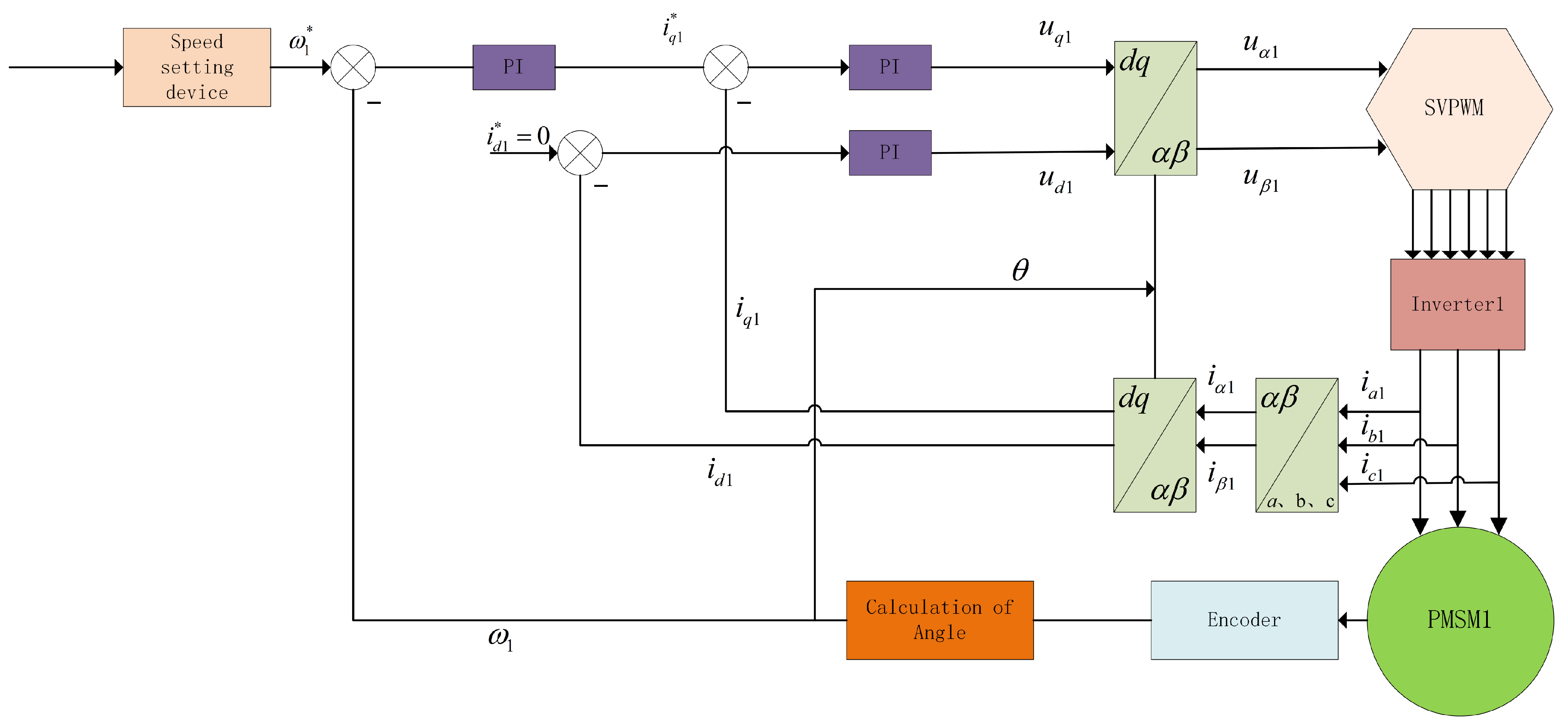
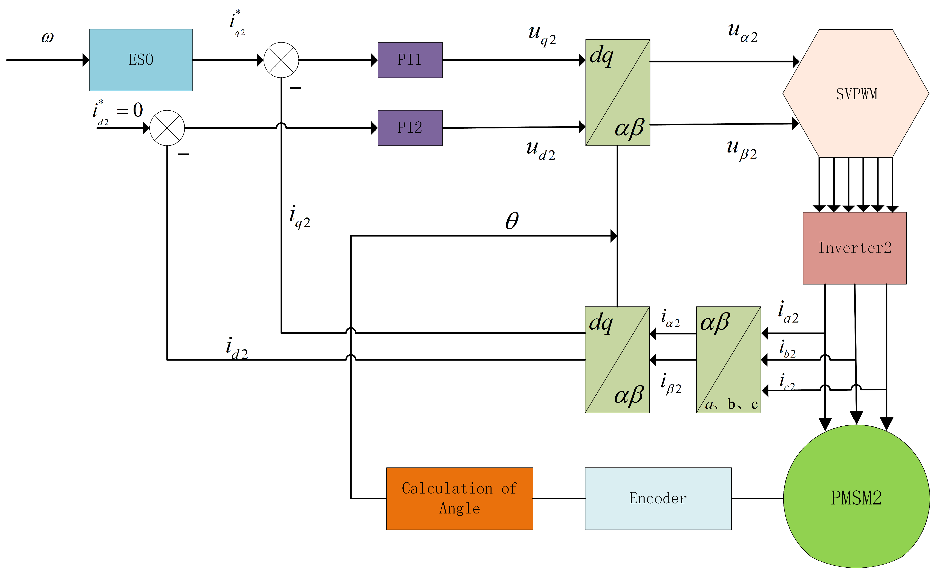
Based on the dual-motor control principle, the control schematic diagram of PMSM 1 is shown in
Figure 3, and the control schematic diagram of PMSM 2 is shown in
Figure 4.
6. Conclusions
To improve the reliability and fault tolerance of electric helicopter flight, this paper presents a dual-redundant electric propulsion system that uses ESO + PI coordinated control. This system uses two relatively independent control systems to power the aircraft and coordinates the operation of the dual motors via a master–slave control architecture. The master controller operates in speed mode, and the slave controller operates in torque mode. The two controllers precisely synchronize through real-time torque information exchange. The system effectively suppresses mechanical coupling interference between the two motors by combining dynamic decoupling control based on an extended state observer with feedforward compensation.
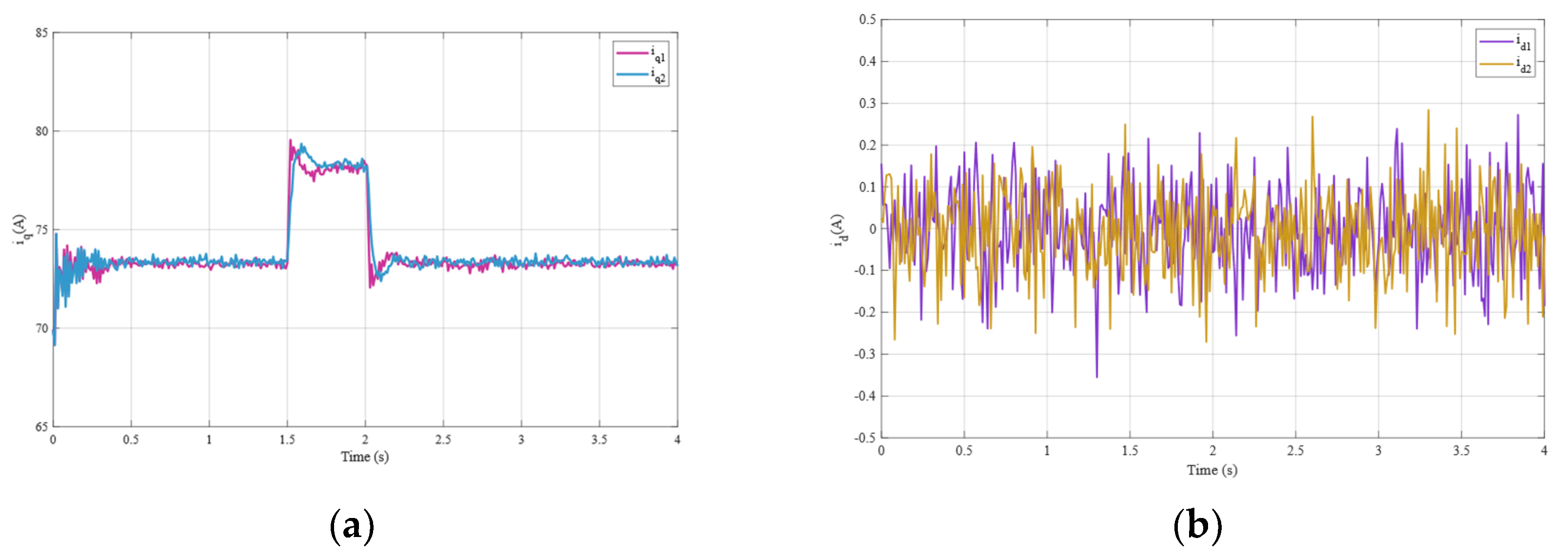
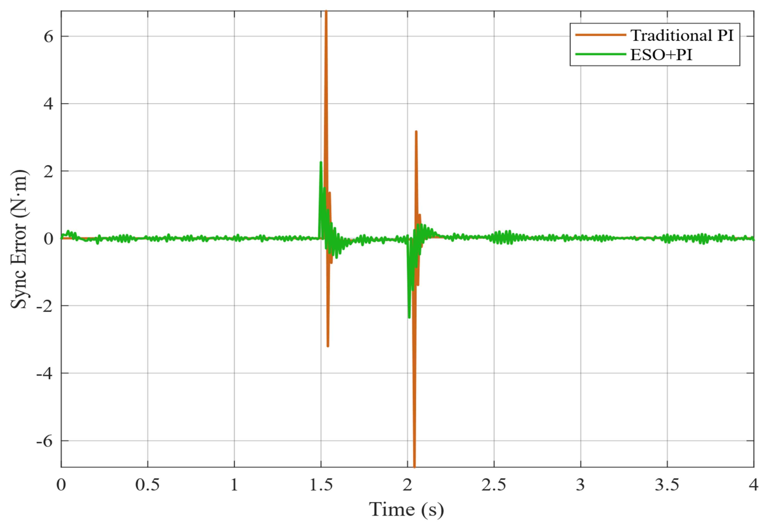
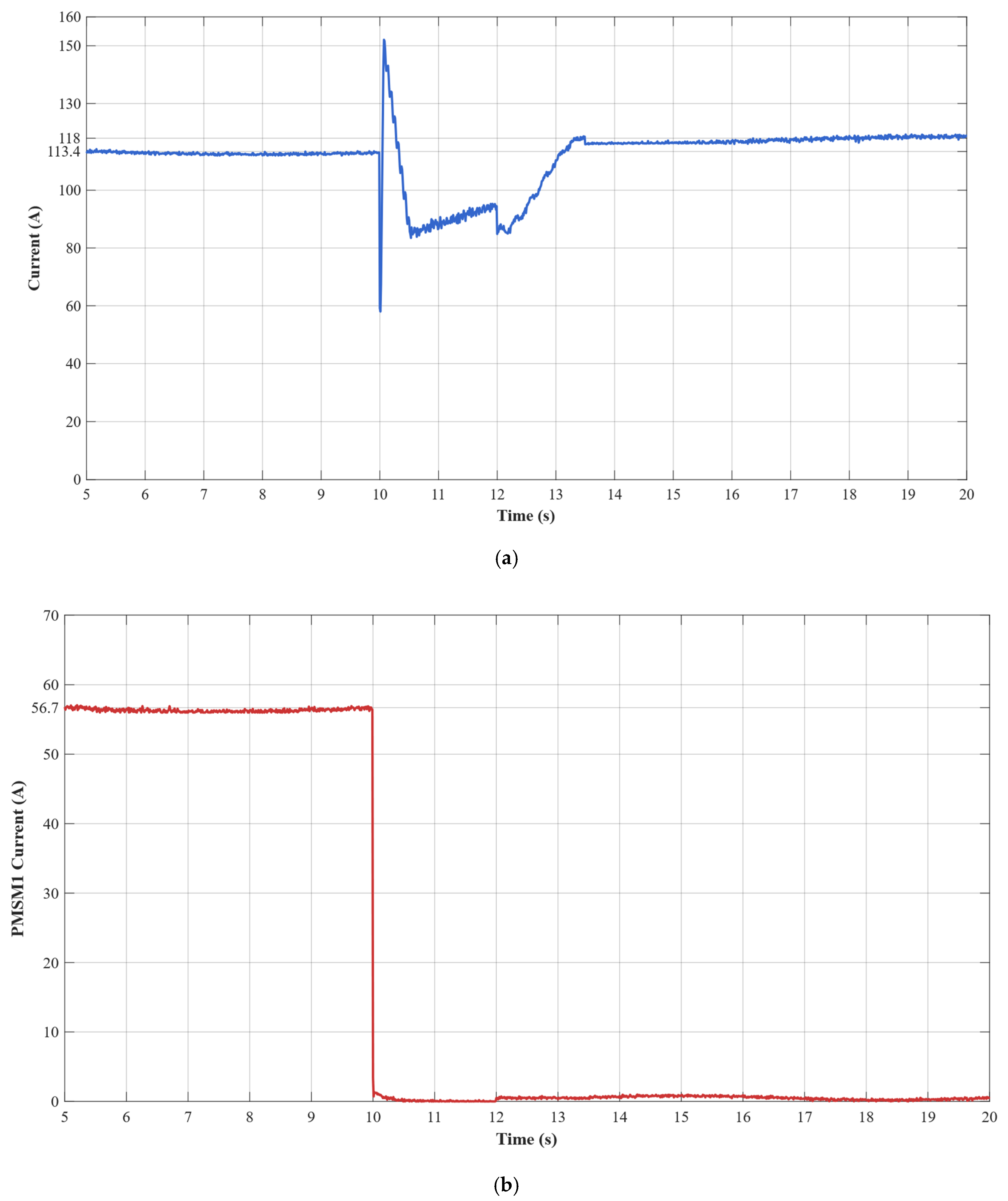
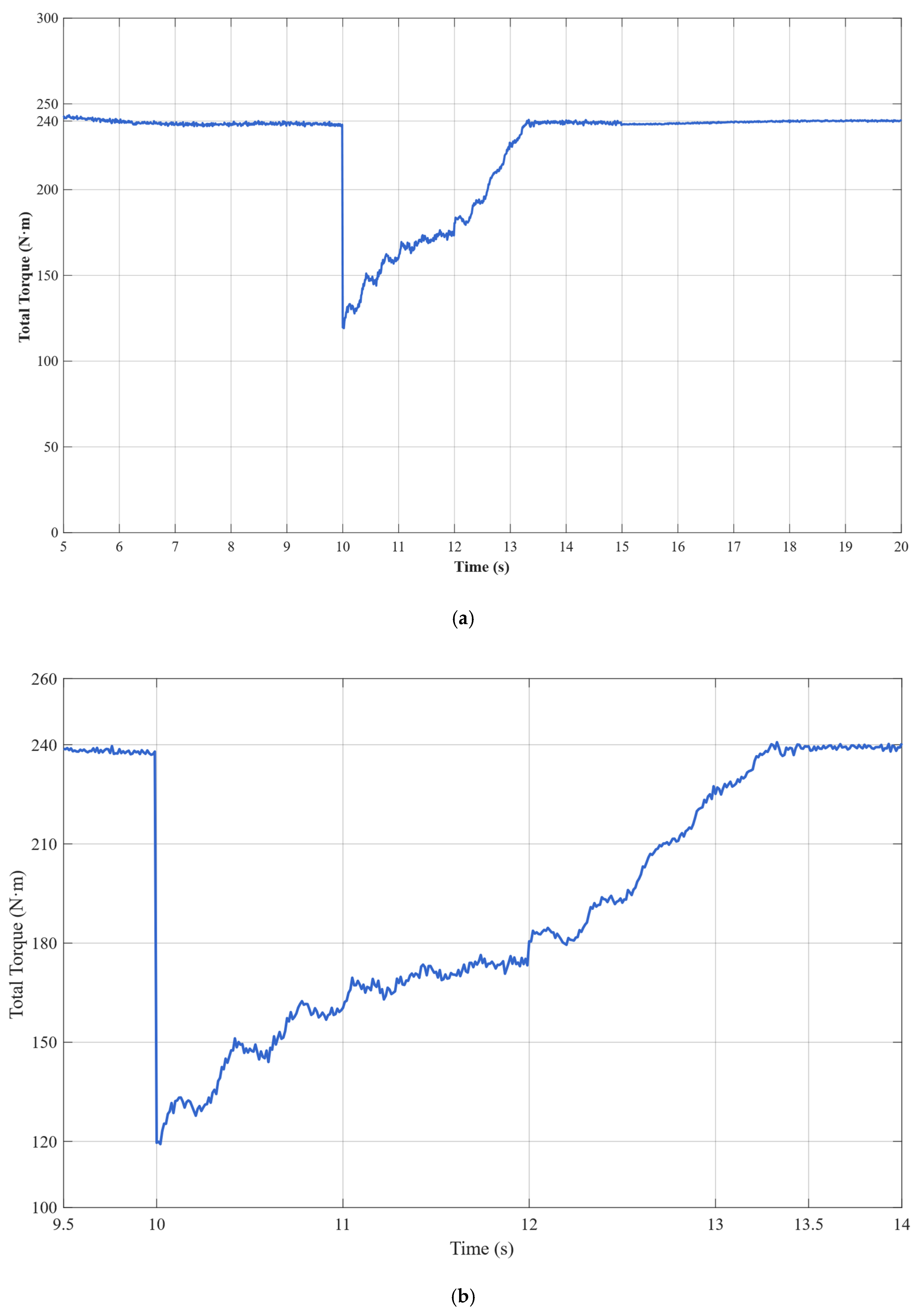
The experimental results demonstrate that the proposed ESO + PI fault-tolerant control strategy performs excellently during critical flight states of electric helicopters. During normal operation, the dual-motor torque synchronization error remains within ±0.5 N·m. Each motor stably outputs 120 N·m of torque at a current of 56.7 A. In the event of a failure in the master motor, the ESO can accurately detect load disturbances within 15 ms with a detection accuracy greater than 95% and rapidly trigger the fault-tolerant control strategy. Upon fault detection, the slave motor immediately switches from torque control mode to speed control mode and assumes the entire system load of 240 N·m.
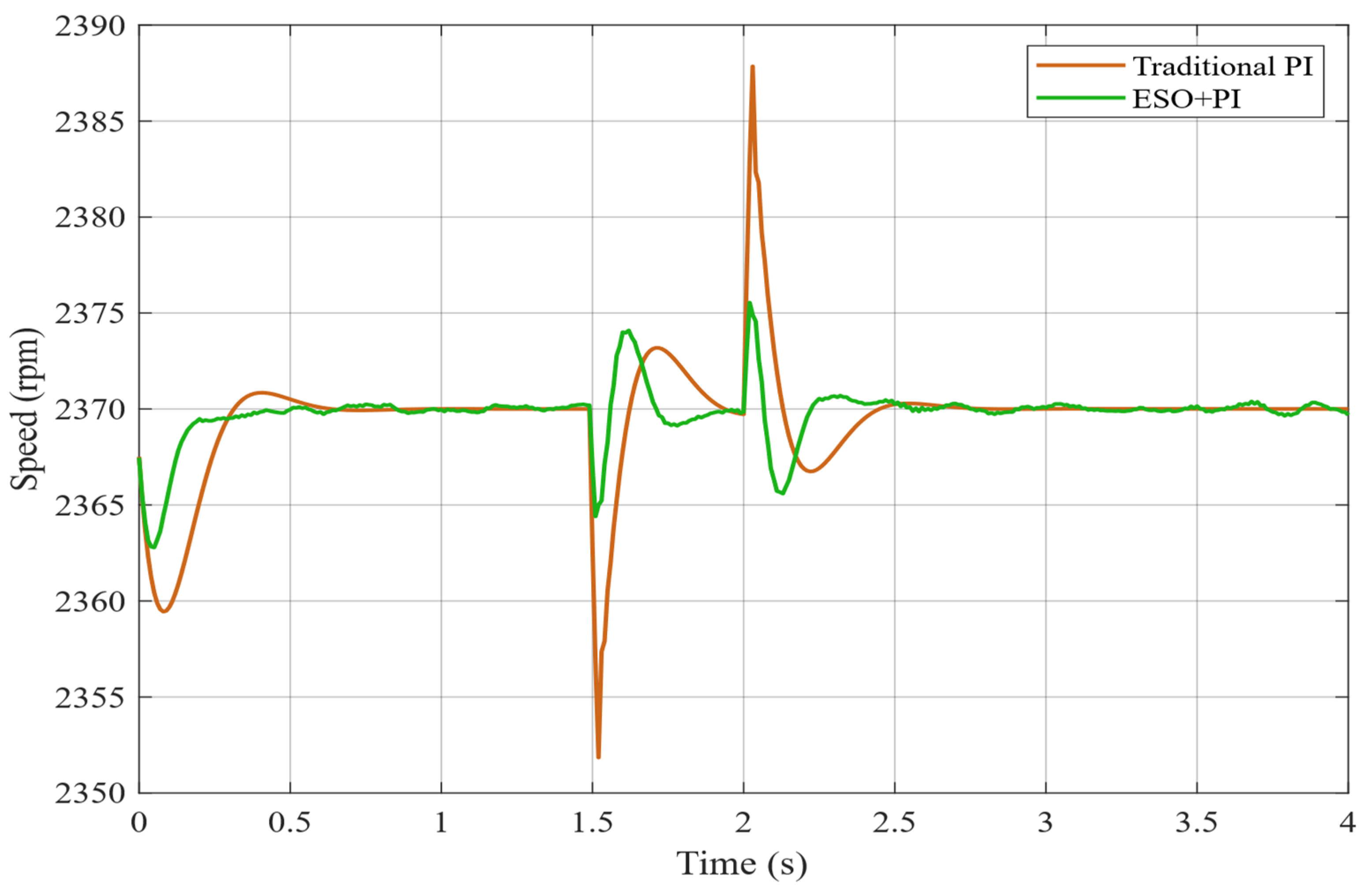
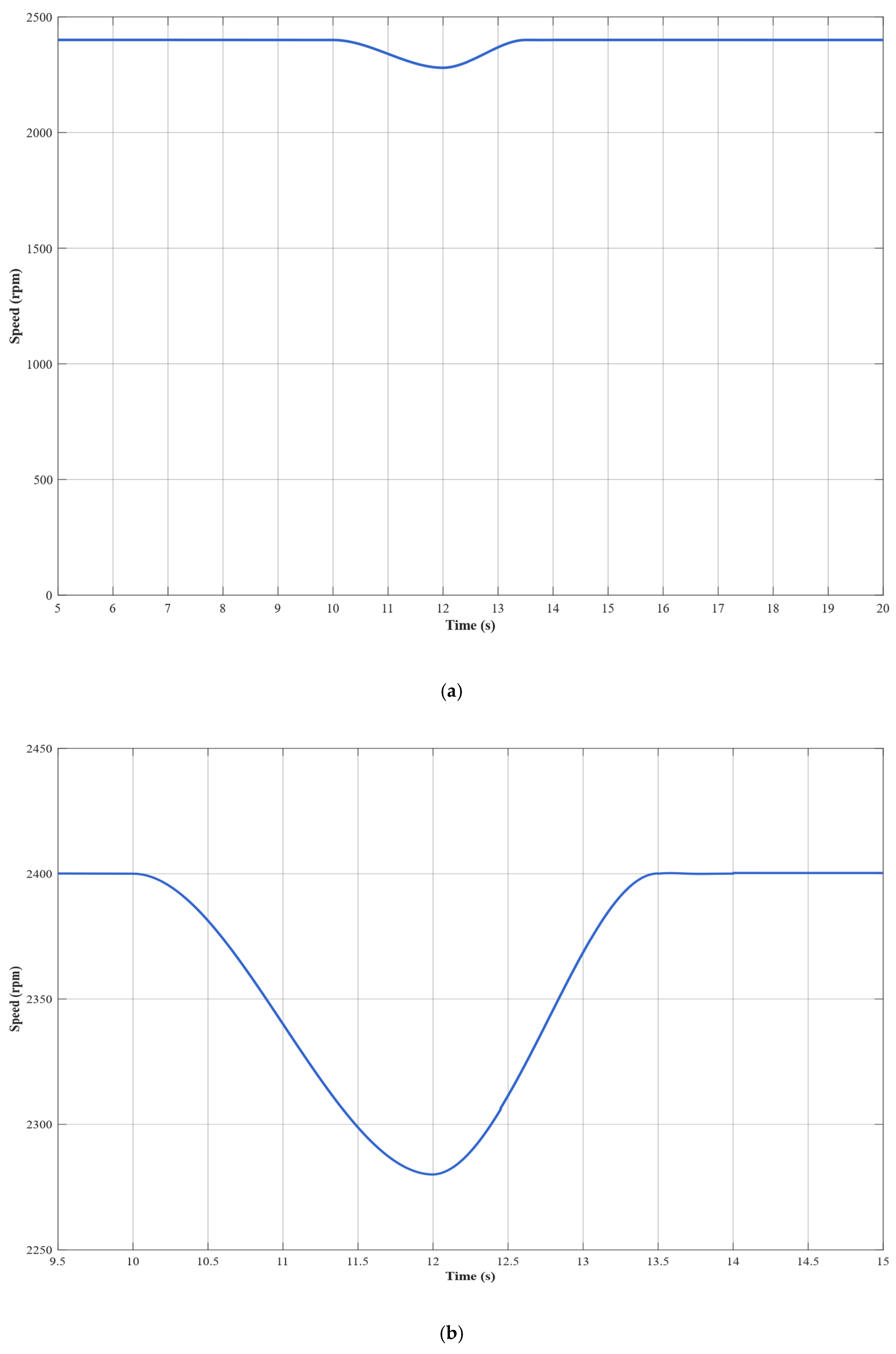
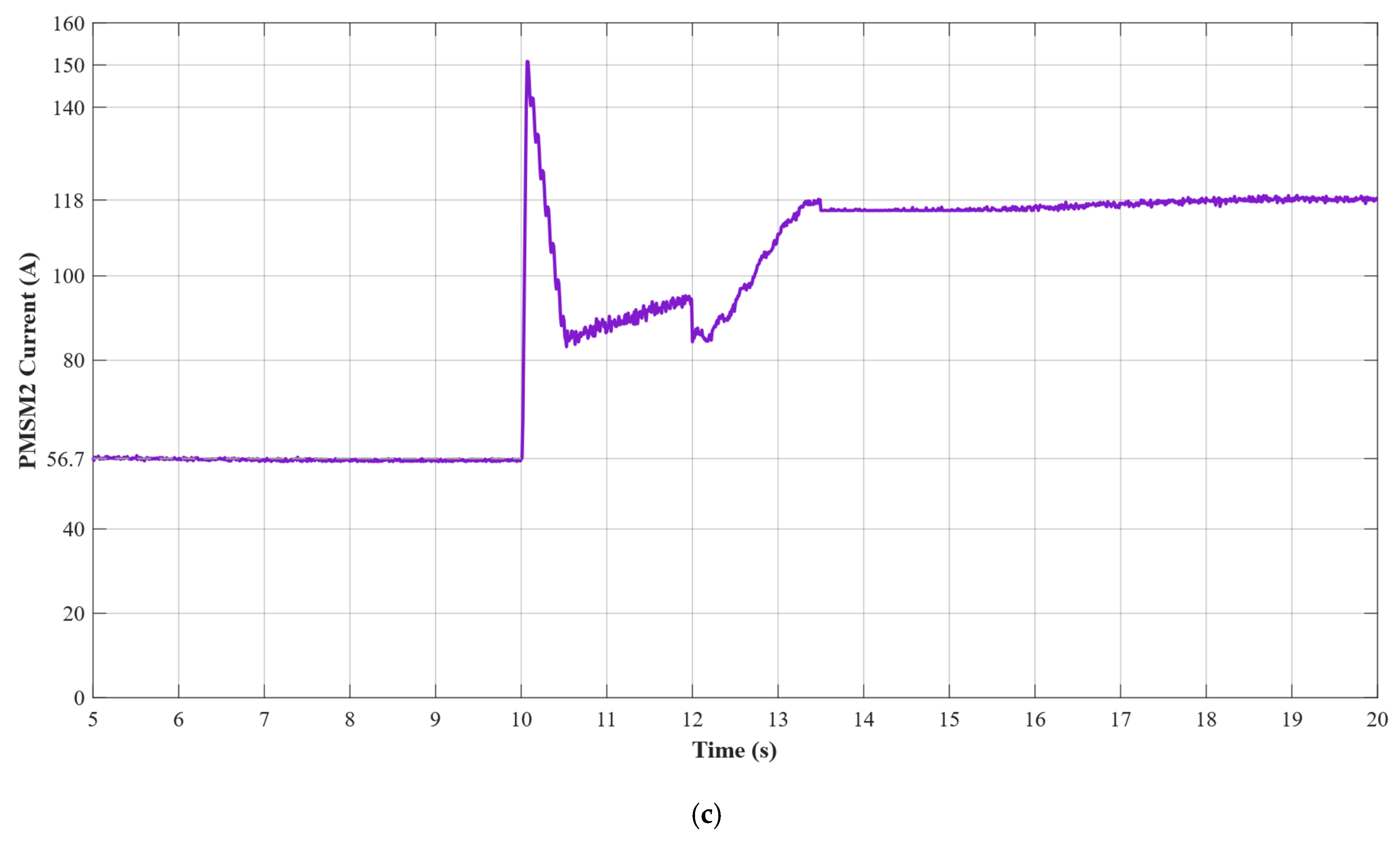
During the fault switching process, the system speed decreases from 2400 rpm to a minimum of 2280 rpm (5% deviation). Through the coordinated actions of ESO feedforward compensation and PI feedback control, the speed recovers within 3.5 s and ultimately stabilizes at 2400 ± 1 rpm. Current response analysis shows that, at the fault instant, the slave motor experiences a transient current overshoot of 150 A. After 3 s of dynamic adjustment, the current stabilizes at 118 A, with only a 4% deviation from the theoretical value of 113.4 A. Compared to traditional PI control, the ESO + PI method improves torque synchronization accuracy by 65.4%, speed stability by 62.6%, and dynamic response speed by 51.2%.
This study validates the dual-redundant electric propulsion system’s high reliability and rapid fault-tolerance capability under single motor failure conditions. This ensures that the electric helicopter’s power system will not fail during emergencies, providing robust flight safety assurance. All of the system’s key performance indicators meet aviation safety standards: fault detection in 15 ms, fault-tolerant switching in 3.5 s, and steady-state accuracy of ±1 rpm. These results provide important theoretical foundations and technical support for the engineering implementation of safety-critical applications, such as electric helicopters.
