Article

Dual-Redundancy Electric Propulsion System for Electric Helicopters Based on Extended State Observer and Master–Slave Fault-Tolerant Control

1
College of Artificial Intelligence, Shenyang Aerospace University, Shenyang 110136, China
2
Key Laboratory of General Aviation, Shenyang Aerospace University, Shenyang 110136, China
3
Liaoning General Aviation Academy, Shenyang 110136, China
*
Author to whom correspondence should be addressed.
Aerospace 2025, 12(9), 847; https://doi.org/10.3390/aerospace12090847
Submission received: 10 August 2025 / Revised: 11 September 2025 / Accepted: 17 September 2025 / Published: 19 September 2025
(This article belongs to the Special Issue Advanced Aircraft Technology (2nd Edition))

Abstract

To improve the reliability and fault tolerance of electric helicopter propulsion systems, this paper presents a master–slave fault-tolerant control method based on an extended state observer (ESO) for dual-redundant electric propulsion systems that addresses dynamic coupling disturbances. First, the control architecture puts the master motor in speed loop mode and puts the slave motor in torque loop mode with an ESO to estimate disturbances and compensate for mechanical coupling torque through feedforward control based on Lyapunov stability theory. Second, a least squares parameter identification method establishes a current-torque mapping model to ensure consistent dual-motor output. Then, fault-tolerant switching is implemented, transitioning from normal torque mode coordination to independent speed mode with adaptive PI adjustment during faults. Experimental validation shows that the total torque stabilizes at 240 N·m, and the synchronization error remains within ±0.5 N·m during normal operation. Under single-motor fault scenarios, the ESO detects disturbances within 15 ms with >95% accuracy. The system speed decreases to a minimum of 2280 rpm (5% deviation) and recovers within 3.5 s. Compared to traditional PI control, this method improves torque synchronization by 65.4%, speed stability by 62.6%, and dynamic response by 51.2%. Finally, the results validate that the method effectively suppresses coupling interference and meets aviation safety standards, providing reliable, fault-tolerant solutions for electric helicopter propulsion.

1. Introduction

Permanent magnet synchronous motors (PMSMs) have been widely used in industrial applications such as aircraft and electric vehicles due to their advantages of high power density, simple structure, and high efficiency [1,2]. However, traditional single-motor drive architectures have gradually shown limitations in addressing challenges such as driving high inertia loads, optimizing dynamic response, and energy-efficient cooperative control. In this context, dual-motor drive systems have emerged as a frontier research direction to meet the requirements of high-power industrial scenarios due to their distinct advantages in power distribution, dynamic compensation, and fault-tolerant control [3].
As a new category of aircraft, electric helicopters have attracted considerable attention in modern aviation due to their low noise, zero emissions, and high energy efficiency [4]. Compared with traditional fuel-powered helicopters, electric helicopters have remarkable advantages in reducing environmental pollution and improving flight efficiency [5]. To further improve the flight performance of electric helicopters, researchers continue to explore more efficient and stable motor control technologies. In particular, some research progress has been made in the synchronized coordination control of dual-motor systems.
In the propulsion system of electric helicopters, dual-motor systems are typically employed to provide redundant power support, thereby enhancing system reliability and fault-tolerant capabilities [6]. The dual-motor system in electric helicopters must not only achieve efficient energy transmission under normal operating conditions but also address dynamic coupling disturbances caused by load variations and aerodynamic perturbations during flight. To mitigate the effects of external disturbances and uncertainties in helicopter systems, ref. [7] proposed a dual-loop control architecture: the inner loop ensures system stability, minimizes tracking errors, and enhances robustness against parametric uncertainties and disturbances; the outer loop guarantees optimal trajectory tracking while avoiding actuator saturation.
In current research on multi-motor synchronization control, ref. [8] proposed a robust synchronous control system for multiple motors based on artificial potential fields and sliding mode variable structure. This system developed a cooperative control strategy for compensating dynamic parameter variations and external disturbances, achieving comprehensive optimization of angular synchronization accuracy and dynamic response robustness. In 1980, Professor Koren introduced a cross-coupled control strategy to realize synchronous coordination control of dual motors [9,10] designed a dual-motor synchronous optimization method based on master–slave cross-coupled synchronization control. By establishing a mathematical model of the hydraulic transmission system, this method performs adaptive interpolation fitting of model parameters according to cable storage states, and embeds an adaptive IMC-PI regulator into the synchronization control strategy. This approach achieves cooperative optimization of dynamic synchronization error compensation and anti-disturbance performance, thereby enhancing operational stability under multiple disturbance conditions. The master–slave control strategy utilizes the output speed of the master motor as the reference speed for the slave motor. Reference [11] developed apermanent magnet synchronous motor drive system employing extended state observer-based sliding mode speed control (ESO-SMSC). Through the establishment of a dynamic motion model, this system collects data on internal parameter variations and external load disturbances. It performs adaptive compensation of control laws based on real-time disturbance estimation and embeds the extended state observer into the sliding mode control framework. This implementation achieves collaborative optimization of speed tracking errors and anti-disturbance capabilities, significantly improving dynamic response speed and steady-state accuracy under parameter mismatch and sudden load conditions. Reference [12] proposed an enhanced extended state observer (ESO) incorporating modified nonlinear functions. Compared to conventional ESO that exhibit deficiencies in nonlinear function continuity and differentiability, this observer effectively suppresses high-frequency chattering phenomena through the introduction of piecewise smooth new-fal functions. The study explored the integration of the improved ESO with sliding mode control laws to compensate in real-time for compound disturbances caused by PMSM parameter perturbations and sudden loads. Closed-loop system stability was demonstrated via Lyapunov function construction, while observer dynamic characteristics were optimized through bandwidth tuning mechanisms. This method demonstrates significant improvements over traditional PI control in torque ripple suppression and speed tracking accuracy. Reference [13] proposed a multiple innovation least squares method with forgetting factors to enhance the convergence speed and identification accuracy of conventional least squares algorithms, effectively suppressing the influence of interference data on identification results. The least squares algorithm is primarily employed for online identification of motor parameters. Through optimization of motor control parameters, it can significantly improve system efficiency and robustness. Reference [14] designed a model predictive current control method for PMSMs based on data-driven recursive least squares estimation. This approach develops control strategies for dynamically adjusting stator current variations, achieving comprehensive optimization control of current tracking accuracy and torque response performance. Reference [15] developed a linear extended state observer to enable real-time observation of current harmonics, utilizing voltage compensation to eliminate harmonic current effects in windings. Compared with hardware redundancy, software redundancy requires no additional hardware components. It enables functional substitution of faulty components through algorithmic implementations, thereby ensuring system reliability and fault-tolerant capabilities [16,17].
This paper proposes an improved dual-motor synchronous coordination control method to address dynamic coupling disturbance issues in electric helicopter dual-motor systems. First, a speed control loop is implemented in the master motor to set the rotor speed reference, while the auxiliary motor adopts a torque control loop. This architecture integrates an extended state observer for real-time disturbance estimation and compensation, effectively suppressing torque fluctuations. Secondly, the online identification of the motor parameters is performed using the least squares method (LSM) [18], accompanied by the design of a torque synchronization-based control law to ensure the consistency of the output torque between the dual motors, further enhancing the system stability and efficiency. Finally, to address the flight safety of electric helicopters, experiments on dual-motor control were conducted. The results demonstrate that the proposed control method effectively enhances flight safety.

2. System Architecture and Mathematical Modeling

2.1. Electric Helicopters Electric Propulsion System

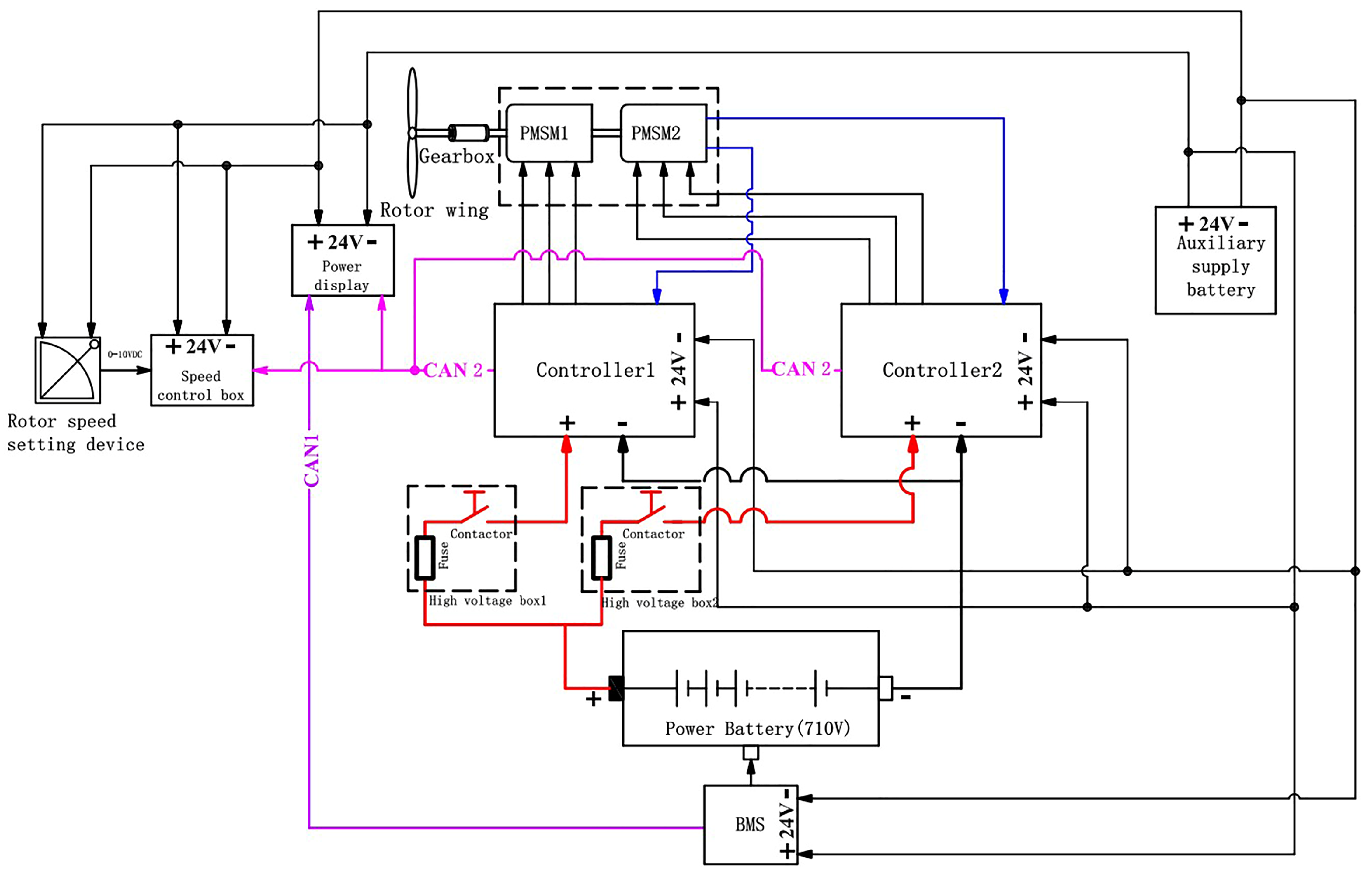
Unlike conventional helicopters, electric helicopters utilize electric propulsion systems to replace internal combustion engines, offering advantages such as high efficiency, environmental friendliness, and low noise. The electric propulsion system primarily consists of a battery pack, controllers, PMSM, and a rotor command unit. The two controllers communicate via CAN bus protocol. The controllers convert DC power from the battery to AC power to drive the PMSMs, which rotate the propellers to generate aerodynamic lift and thrust for the aircraft. The configuration of the electric helicopter propulsion system is shown in Figure 1.

2.2. PMSM Structure Model

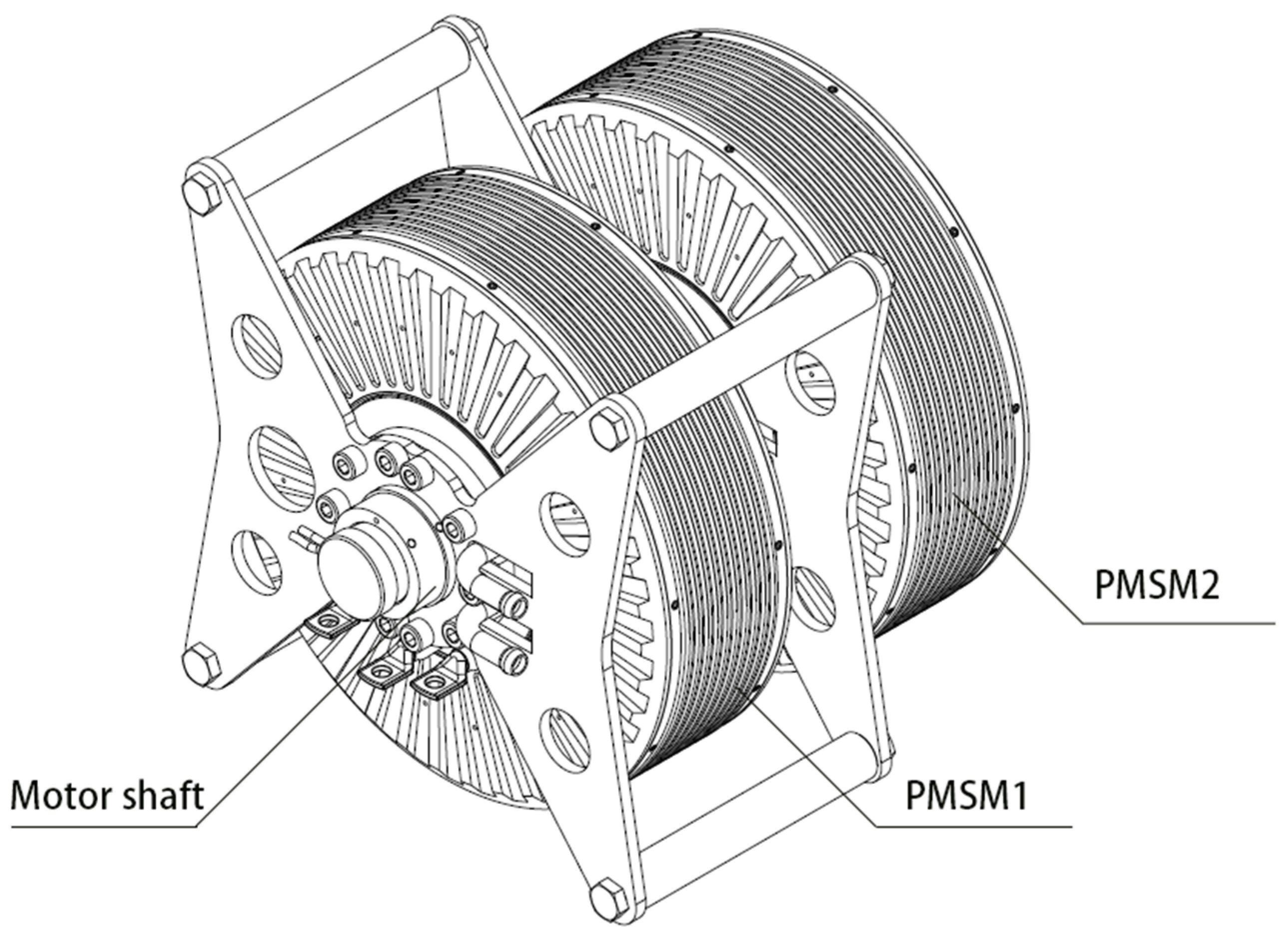
As shown in Figure 2, the schematic diagram illustrates the configuration of a dual-series PMSM system. Two PMSMs are arranged coaxially in a tandem mounting structure to achieve stable flight and precise maneuverability for helicopters. This design not only meets the thrust requirements of the aircraft but also maintains lateral stability during flight operations, significantly enhancing helicopter safety.

2.3. PMSM Mathematical Model

Prior to establishing the motor mathematical model, the following preconditions are defined for the permanent magnet synchronous motors [19]:
  • Surface-mounted permanent magnet synchronous motors are employed.
  • Two motors with identical parameters are connected in a co-axial series configuration.
  • Iron losses in the magnetic circuit and air gap flux harmonics are neglected.
Through the above processing, the mathematical model of the PMSM system voltage can be obtained as follows:
u d i = R i d i + L d d i d i d t ω i L q i q i
where i is the subscript used to label the variables of the i-th PMSM, i = 1,2, udi is the voltage of d axis, respectively, R is the stator resistance, idi is the current of d axis, respectively, Ld and Lq are the inductance of d-q axis, respectively, ω i is the rotating angular velocity of PMSM, ω i L q i q i refers to the back electromotive force induced in the d-axis.
u q i = R i q i + L q d i q i d t + ω i L d i d i + ω i ψ
where uqi is the voltage of q axis, respectively, iqi is the current of q axis, respectively, ω i L d i d i refers to the electromotive force induced in the q-axis. ω i ψ represents the electromotive force generated by the magnetic flux linkage of the permanent magnet. ψ represents the magnetic flux linkage of the permanent magnet. The electromagnetic torque of permanent magnet synchronous motor is expressed as follows:
T i e = 3 2 p [ ψ i q i + ( L d L q ) i d i i q i ]
where p is the number of stator pole pairs, Tie represents the electromagnetic torque. For surface-mounted permanent magnet motors, Ld = Lq based on the processing (4); Equation (3) can be simplified as follows:
T i e = 3 2 p ψ i q i
Two table-mounted permanent magnet synchronous motors of the same parameters are connected in coaxial series with the same angular speed:
ω 1 = ω 2 = ω
The motion equation of PMSM is expressed as follows:
J d ω i d t = T i e T L B ω i
where TL represents the load torque, B and J are the viscous damping and rotor inertia, respectively.
The two motors are coaxially connected, and the combined dynamical equation is expressed as
2 J d ω d t = T 1 e + T 2 e ( B 1 + B 2 ) ω T L
Substitute the parameter consistency condition:
2 J d ω d t = 3 2 p ψ ( i q 1 + i q 2 ) 2 B ω T L

3. Dual-Motor Control Strategy Design

The dual-redundancy electric propulsion control system adopts a speed-torque dual-loop coordinated control architecture based on dynamic decoupling. In the torque loop design, ESO enables real-time estimation of load torque and unknown disturbances, coupled with a feedforward compensation mechanism to eliminate mechanical coupling effects between dual motors. Concurrently, a high-fidelity current-to-torque mapping model is established through least squares parameter identification, ensuring output torque consistency across both motors. The speed loop design dynamically compensates for synchronization error signals from the master–slave system using an adaptive PI controller. This architecture integrates CAN bus communication to achieve speed-independent control under fault conditions and seamless mode transition during system reconfiguration.
The master motor tracks the prescribed rotational speed ω through a PI controller, generating the q-axis current reference command i q 1 .
e ω = ω ω i q 1 = K p 1 e ω ( t ) + K i 1 0 t e ω ( τ ) d τ
where e ω denotes the speed error between the reference and feedback values, t represents the integral time constant, kp1 is the proportional gain, and ki1 is the integral gain of the controller.
The parameter tuning of the PI controller in the speed outer loop can be transformed into the parameter optimization for a Type II system. By calculating the open-loop transfer function of the speed control loop and comparing it with the standard Type II system transfer function, we derive the optimal parameters of the speed loop’s open-loop transfer function corresponding to the best dynamic performance of the Type II system. This allows us to determine the proportional gain kp1 and integral gain ki1 of the PI controller.
The transfer function G(s) can be expressed as
G s = 45 p ψ k i 1 π J k p 1 k i 1 s + 1 s 2 4 T s s + 1
where Ts is the sampling time.
The transfer function of a canonical Type II system can be expressed as
G s = K τ s + 1 s 2 T s + 1
where K is the open-loop gain, τ is the delay time, and T is the time constant of the system.
In a typical type II system, the IF width with a slope of −20 dB/sec is defined as h. The best PMSM dynamic following performance is achieved when the IF width h = 5. According to the principle of minimum, the peak value of the closed-loop amplitude-frequency characteristic, the values of kp1 as well as ki1 can be known:
k i 1 = π J 375 p ψ T 2 , k p 1 = π J 75 p ψ T
In the dual-motor system, the auxiliary motor (PMSM 2) is controlled using a torque loop strategy. The aim is to ensure that the electromagnetic torque of the auxiliary motor follows the reference torque, while compensating for load disturbances and mechanical coupling effects through feedforward compensation of the estimated disturbance.
T 2 e = T 2 e + d
T 2 e = T 2 e , r e f d
where (13) denotes the torque command, T2e,ref denotes the reference torque and d represents the estimated disturbance (including load torque TL and coupling effects) for external influence compensation.
According to (7), the disturbance definition d = −TL, the motion equation can be rewritten as
ω · = B J ω + 1 J ( T 1 e + T 2 e ) + 1 J d
To estimate the disturbance d, it is treated as an extended state z = d, with the assumption that its derivative z · = d · = ξ (where ξ is generally unknown). Taking the rotational speed x = ω as the state variable, the system dynamics can be expressed as
x · = B J x + 1 J ( T 1 e + T 2 e ) + 1 J z
Standard canonical formulation:
x · = f ( x ) + g u + b z
where
f ( x ) = B J x g = 1 J u = T 1 e + T 2 e b = 1 J z = d
Augmented state-space equations:
x · = f ( x ) + g u + b z z · = ξ
ESO generates estimates of the state x and disturbance z, with the estimated values denoted as x and z . The ESO dynamics are governed by the following equations:
x · = f ( x ) + g u + b z + l 1 ( x x ) z · = l 2 ( x x )
where l 1 ,   l 2 are observer gains.
Substitute parameters:
x · = B J x + 1 J ( T 1 e + T 2 e ) + 1 J d + l 1 ( x x ) d · = l 2 ( x x )
Define the estimation error e = x x , disturbance estimation error d ~ = d d .
The dynamic of error:
e · = x · x · = f ( x ) f ( x ) + b ( d d ) l 1 e
Substitute parameters:
e · = B J e + 1 J d ~ l 1 e = ( B J + l 1 ) e + 1 J d ~
Substitute parameters:
d ~ · = d · d · = ξ l 2 e
The error system:
e · d ~ · = ( B J + l 1 ) 1 J l 2 0 e d ~ + 0 ξ
If ξ = 0, the characteristic polynomial is the translation:
s 2 + ( B J + l 1 ) s + l 2 J = 0
Choose the gain l 1 = 2 ω 0 B J , l 2 = J ω 0 2 such that the characteristic polynomial is
s 2 + 2 ω 0 s + ω 0 2 = ( s + ω 0 ) 2
The characteristic roots are located at s = −ω0 (with multiplicity), ensuring the stability of the ESO and allowing its convergence rate to be regulated by adjusting ω0.
If ξ 0 , s = −ω0 (with multiplicity), ensuring a Hurwitz matrix.
To analyze the bounded-input bounded-output (BIBO) stability of the ESO system, we derive the transfer functions from the error dynamics Equation (25). Taking the Laplace transform of Equation (25) with ξ as input and considering zero initial conditions, we obtain the following transfer functions:
G e ( s ) = 1 J ( s + ω 0 ) 2
G d ( s ) = s + 2 ω 0 ( s + ω 0 ) 2
where Ge(s) is transfer function from input disturbance ξ(t) to state estimation error, Gd(s) is transfer function from input disturbance ξ(t) to disturbance estimation error.
In practical helicopter applications, external disturbances are typically bounded but persistent, ∣ξ(t)∣ ≤ Dmax, where Dmax is a known positive constant.
Under persistent bounded disturbances, the ESO achieves bounded steady-state estimation errors:
e s s D max J ω 0 2
d s s 2 D max ω
where the state estimation error is ess, and the disturbance estimation error is dss.
The error bounds decrease with higher observer bandwidth ω0, enabling predictable performance tuning. This bounded-error property ensures reliable torque estimation for dual-motor coordination under realistic flight disturbances.
As derived from Equation (4), the torque coefficient is defined as K = 1.5 , yielding the electromagnetic torque relationship Te = Kiq. To enhance estimation accuracy, the LSM is employed for online identification of K. By collecting data pairs (iq(k), Te(k)), the objective is to minimize the sum of squared errors:
J ( K ) = k = 1 N ( T e ( k ) K i q ( k ) ) 2
Estimated value:
K = k = 1 N i q ( k ) T e ( k ) k = 1 N i q ( k ) 2
Estimation of magnetic flux linkage:
ψ = K 1.5 p
To ensure that the torque of both motors is the same, the PI controller is designed to adjust the current command of the auxiliary motor.
To ensure consistent torque output between the dual motors, a PI controller was designed to regulate the q-axis current reference i q 2 of the slave motor.
i q 2 = T 2 e , r e f d 1.5 p ψ + k p 2 ( T 1 e T 2 e ) + k i 2 ( T 1 e T 2 e ) d t
The slave motor electromagnetic torque satisfaction:
T 2 e = 3 2 p ψ i q 2
Assuming that the current loop response speed is much higher than the torque loop response speed, we can approximate iq2 = iq2*. Substituting (35) into (36), we obtain the following:
T 2 e 3 2 p ψ [ T 2 e , r e f d 1.5 p ψ + k p 2 ( T 1 e T 2 e ) + k i 2 ( T 1 e T 2 e ) d t ]               ( T 2 e , r e f d ) + 3 2 p ψ [ k p 2 ( T 1 e T 2 e ) + k i 2 ( T 1 e T 2 e ) d t ]
From this, we can conclude that
e T ( s ) [ 1 + 3 2 p ψ ( k p 2 + k i 2 s ) ] = T 1 e ( s ) ( T 2 e , r e f ( s ) d ( s ) )
where eT(s) = T1(s) − T2(s). T1(s) is the master motor electromagnetic torque, and T2(s) is the slave motor electromagnetic torque. This equation represents the closed-loop torque synchronization dynamics of the dual-motor system. The left side shows the torque synchronization error eT(s) = T1(s) − T2(s) modified by the closed-loop transfer function 1 + 3 2 p ψ ( k p 2 + k i 2 s ) , where the term 3 2 p ψ ( k p 2 + k i 2 s ) represents the PI controller’s contribution to torque regulation with kp2 and ki2 being the proportional and integral gains, respectively. The right side T 1 e ( s ) ( T 2 e , r e f ( s ) d ( s ) ) indicates that the torque error dynamics are driven by the difference between the master motor electromagnetic torque T1e(s) and the compensated slave motor reference torque, where d ( s ) provides ESO-based feedforward disturbance compensation. This relationship ensures that the torque synchronization error approaches zero in steady state, achieving precise dual-motor coordination under the combined action of PI feedback control and ESO feedforward compensation.
The characteristic equation of the transfer function of Equation (38) is
s 2 + 3 2 p ψ k p 2 s + 3 2 p ψ k i 2 = 0
This equation corresponds to a standard second-order system:
s 2 + 2 ζ ω n s + ω n 2 = 0
Among them, natural frequency:
ω n = 3 2 p ψ k i 2 , 2 ζ ω n = 3 2 p ψ k p 2
Derive the parameter formula from this.
k p 2 = 4 ω n 3 p ψ ,     k i 2 = 2 ω n 2 3 p ψ
To ensure the global asymptotic stability and robustness of the dual-motor torque synchronization control system for electric helicopters, we define the Lyapunov function with the following variables:
Define torque coefficient estimation error as K ~ = K K , where K is the torque coefficient, and K is the estimated value via the least squares method.
V = 1 2 J e ω 2 + 1 2 e 2 + 1 2 d ~ 2 + 1 2 K ~ 2 + 1 2 e T 2
The differentiation of V can be obtained as
V · = J e ω e · ω + e e · + d ~ d ~ · + K ~ K ~ · + e T e T ·
Substituting e · ω = k ω e ω , e · = ( B J + l 1 ) e + 1 J d ~ , d ~ · = l 2 e , K ~ · = γ i q 2 K ~ , e · T = k e T into (44), the differentiation of V can be obtained as
V · = J e ω ( k ω e ω ) + e ( B J + l 1 ) e + 1 J d ~ + d ~ ( l 2 e ) + K ~ ( γ i q 2 K ~ ) + e T ( k e T ) = J k ω e ω 2 ( B J + l 1 ) e 2 + 1 J e d ~ l 2 e d ~ γ i q 2 K ~ 2 k e T 2 = J k ω e ω 2 ( B J + l 1 ) e 2 γ i q 2 K ~ 2 k e T 2 + ( 1 J l 2 ) e d ~
By setting l 2 = 1 J , the cross-coupling terms are eliminated:
V · = J k ω e ω 2 ( B J + l 1 ) e 2 γ i q 2 K ~ 2 k e T 2
Because k ω , l 1 , γ , k > 0, and i q 2 > 0, V · 0 . The system is stable.
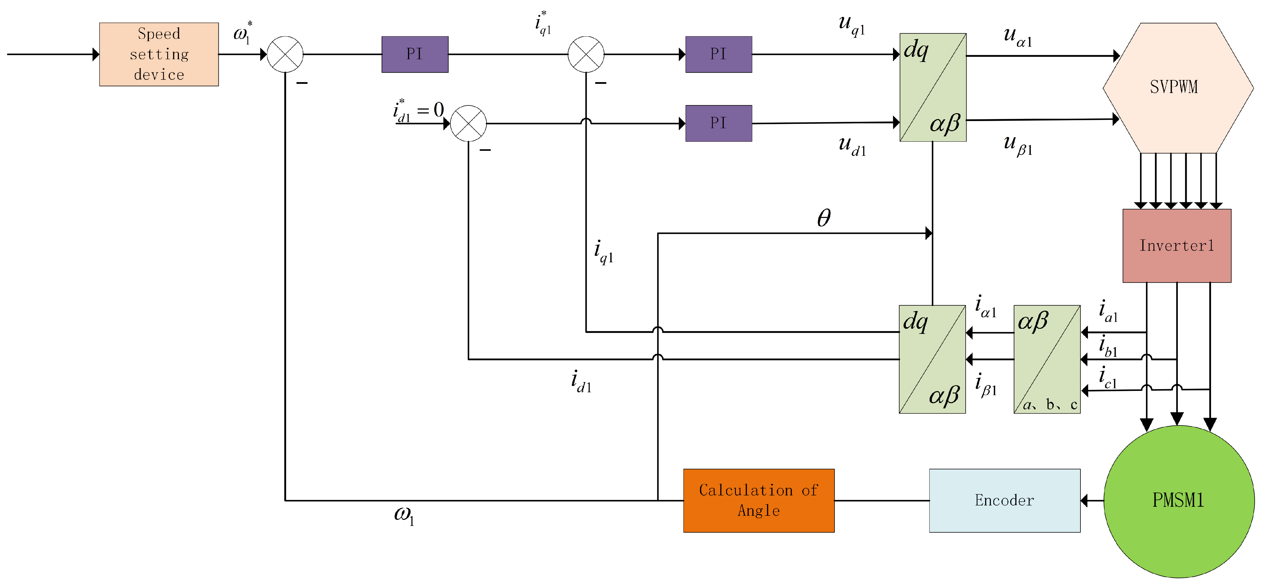
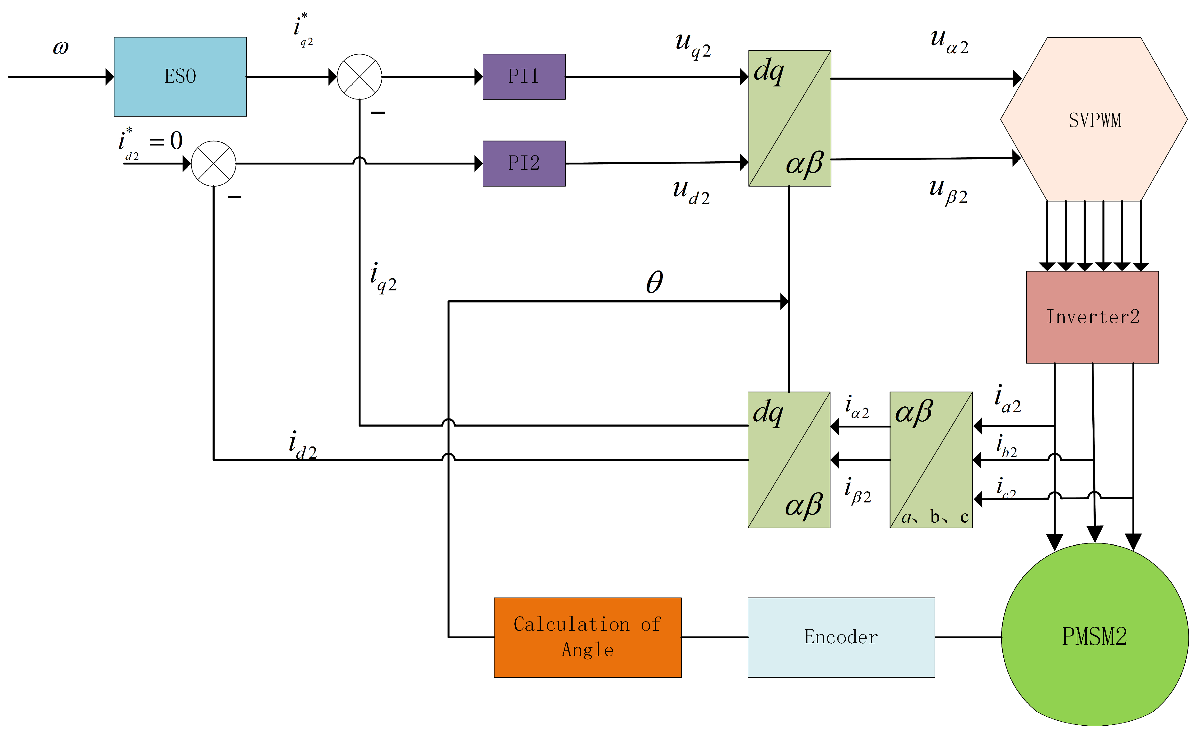
Based on the dual-motor control principle, the control schematic diagram of PMSM 1 is shown in Figure 3, and the control schematic diagram of PMSM 2 is shown in Figure 4.

4. Simulation and Analysis

4.1. Dual-Motor ESO Torque Synchronization Control Simulation Experiment

4.1.1. Experimental Purpose

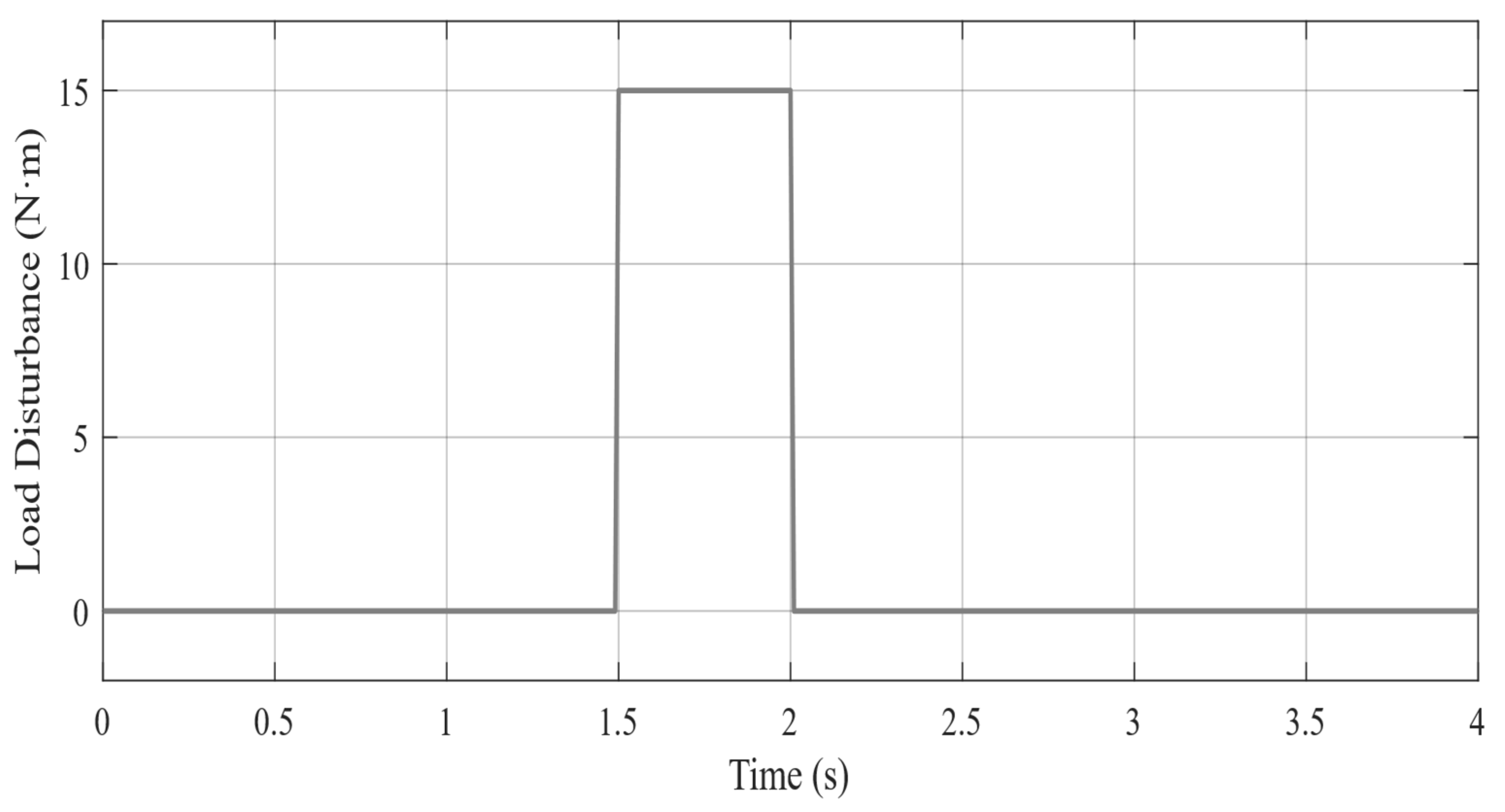
To validate the effectiveness of the proposed ESO-based dual-motor torque synchronization control strategy, quantitative assessments are conducted on the system’s disturbance rejection capability, torque synchronization precision, and real-time response characteristics. Step load disturbances are designed to evaluate the anti-disturbance performance: a 15N·m step load disturbance is imposed during the 1.5–2.0 s interval to emulate sudden updraft encounters in electric helicopter operations. The simulation spans 4 s with a sampling interval of 0.01 s.

4.1.2. Experimental Conditions

The simulation conditions are configured as follows: the helicopter is assumed to be in hovering state with rotational speed of 2370 rpm and total torque of 220 N·m, where the target torque for each individual motor is set to 110 N·m. The simulation duration is 4 s with PMSM startup initiated at t = 0 s. To emulate the scenario of sudden updraft encounters during helicopter flight operations, a 15 N·m load disturbance is imposed at t = 1.5 s.

4.1.3. Simulation Experimental Results

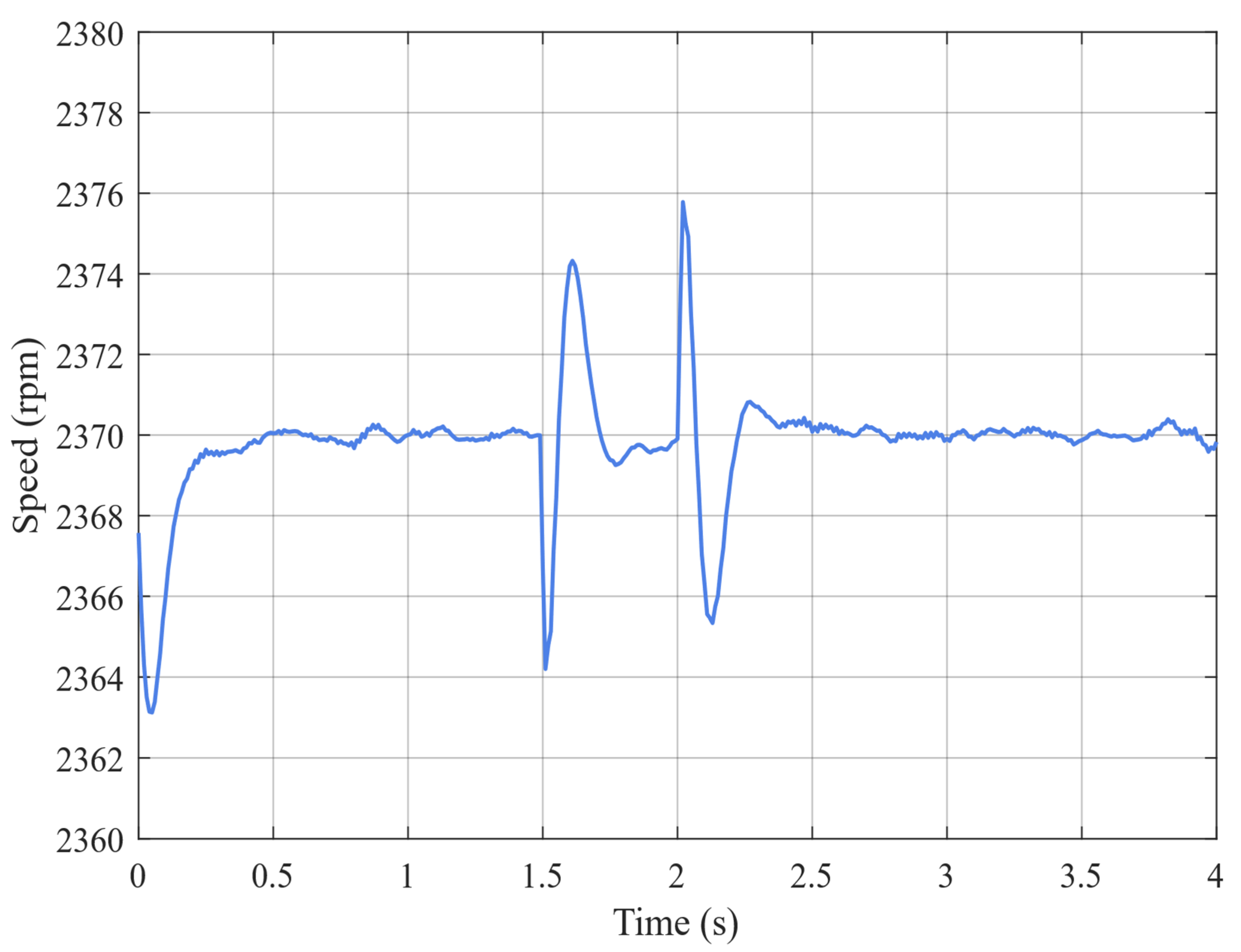
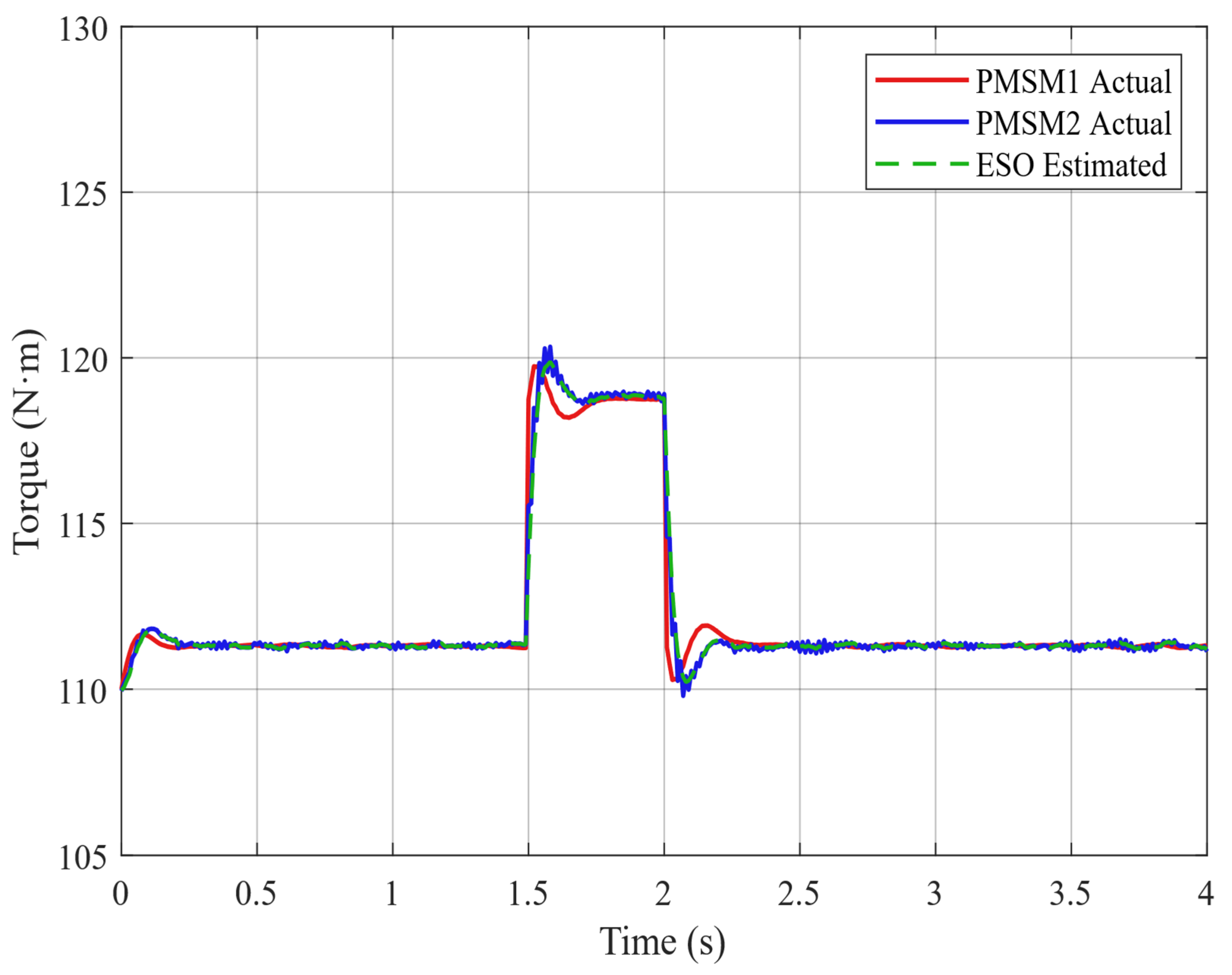
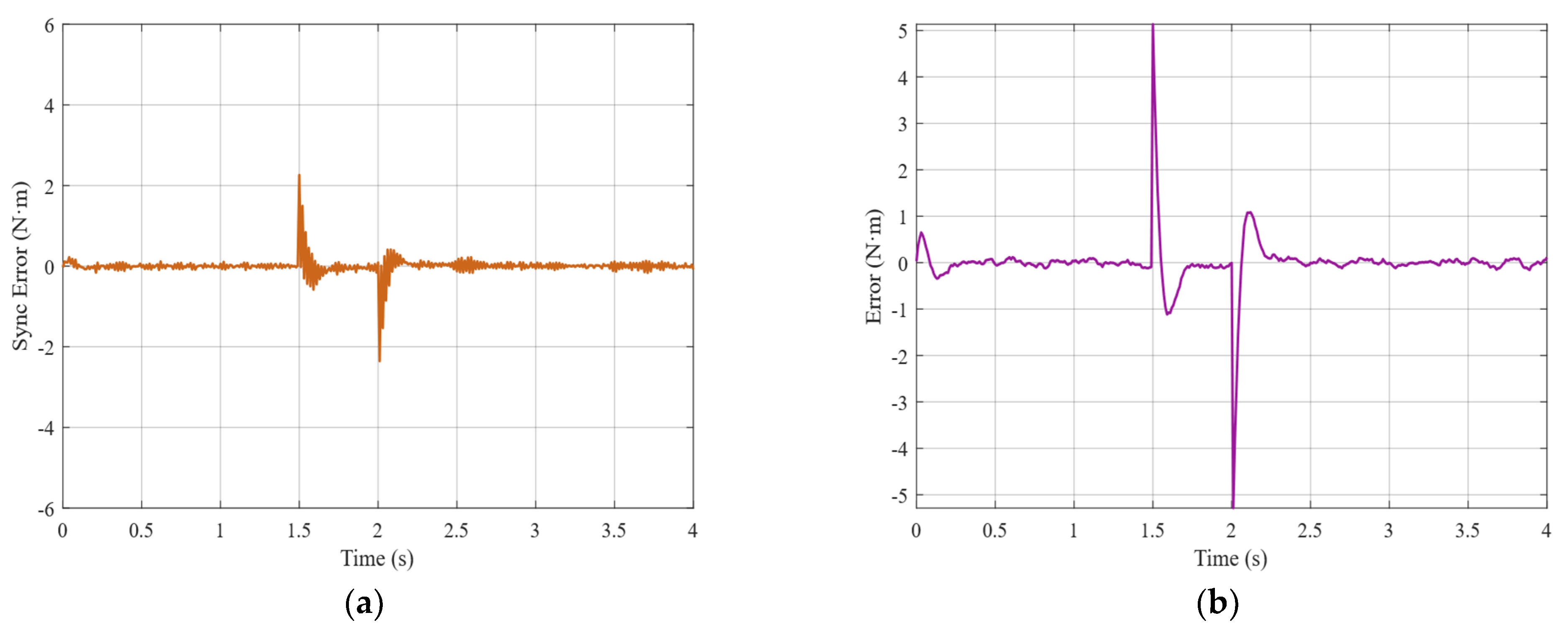
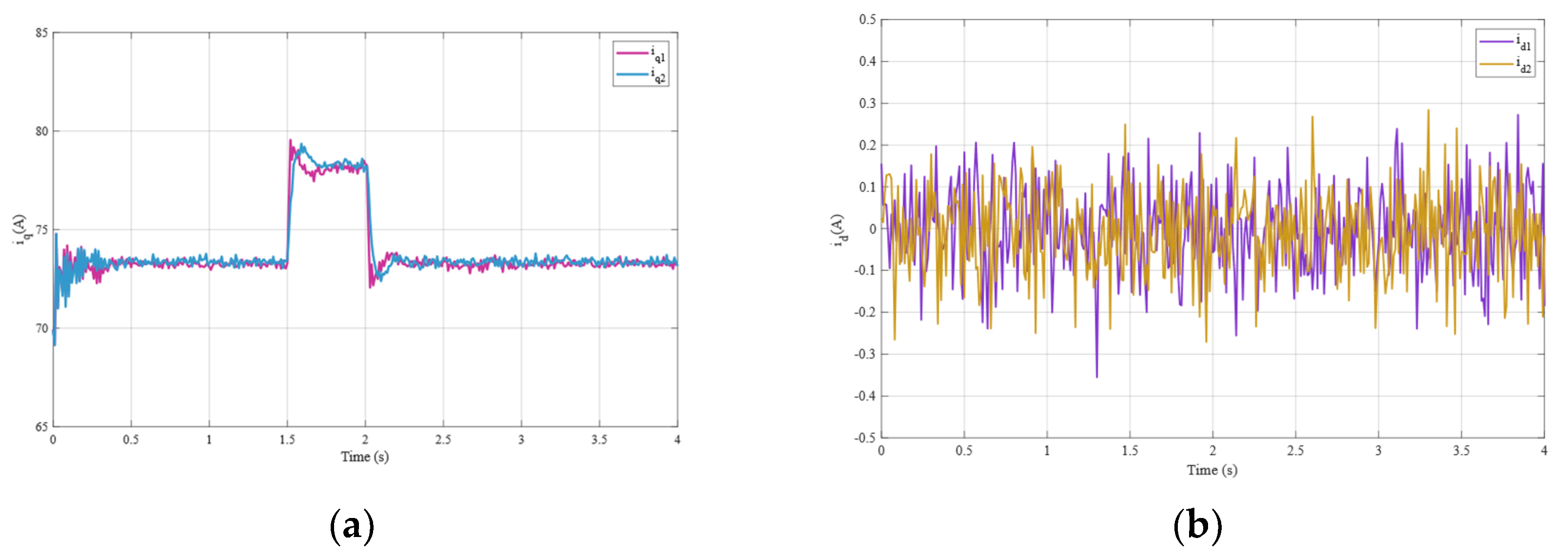
The simulation results are presented in Figure 5, Figure 6, Figure 7, Figure 8 and Figure 9. Figure 6 illustrates the speed response characteristics of the dual-motor system under load disturbances. During the 0.5–1.5 s interval, the rotational speed remains stable at 2370 ± 1.2 rpm. Upon the sudden load increase at t = 1.5 s, the speed decreases to a minimum of 2364.2 rpm (5.8 rpm drop) and recovers to the target value within 0.2 s, satisfying fast response requirements. Figure 7 reveals that under nominal conditions, both Te1 and Te2 maintain stability at 110 N·m with equal load distribution. During the 1.5 s disturbance, PMSM1 torque rises to 119 N·m, with ESO estimation accurately tracking after a 15 ms delay, while PMSM2 torque synchronizes to 119 N·m within 25 ms, achieving rapid inter-motor torque synchronization. This validates the ESO’s capability for precise main motor torque estimation and the rapid tracking performance of the slave motor. Figure 8 demonstrates torque synchronization error dynamics, with steady-state errors maintained within ±0.5 N·m. The peak synchronization error reaches 2.3 N·m at the disturbance instant, converging to ±0.5 N·m within 40 ms, exhibiting excellent dynamic response characteristics. As shown in Figure 9, the experimental validation demonstrates the effectiveness of the proposed ESO-based dual-motor control strategy through comprehensive current response analysis. During normal operation, both iq1 and iq2 remain stable at approximately 72.4 A. The synchronization error between dual motors is maintained within ±0.5 A, validating the precision of the ESO + PI coordinated control architecture. When subjected to the 15 N·m step load disturbance, both q-axis currents rapidly increase to a peak value of approximately 79 A, representing a 6.6 A increment. Concurrently, the d-axis currents id1 and id2 consistently oscillate around 0 A with amplitudes of ±0.3 A throughout the entire experiment, confirming the surface-mounted PMSM characteristic where id ≈ 0. These small random variations primarily originate from measurement noise and minor controller adjustments, indicating stable field-oriented control performance. The comprehensive current analysis validates both the physical consistency of the motor model and the robust performance of the proposed fault-tolerant control strategy under various operating conditions.

4.2. Experimental Comparison and Summary

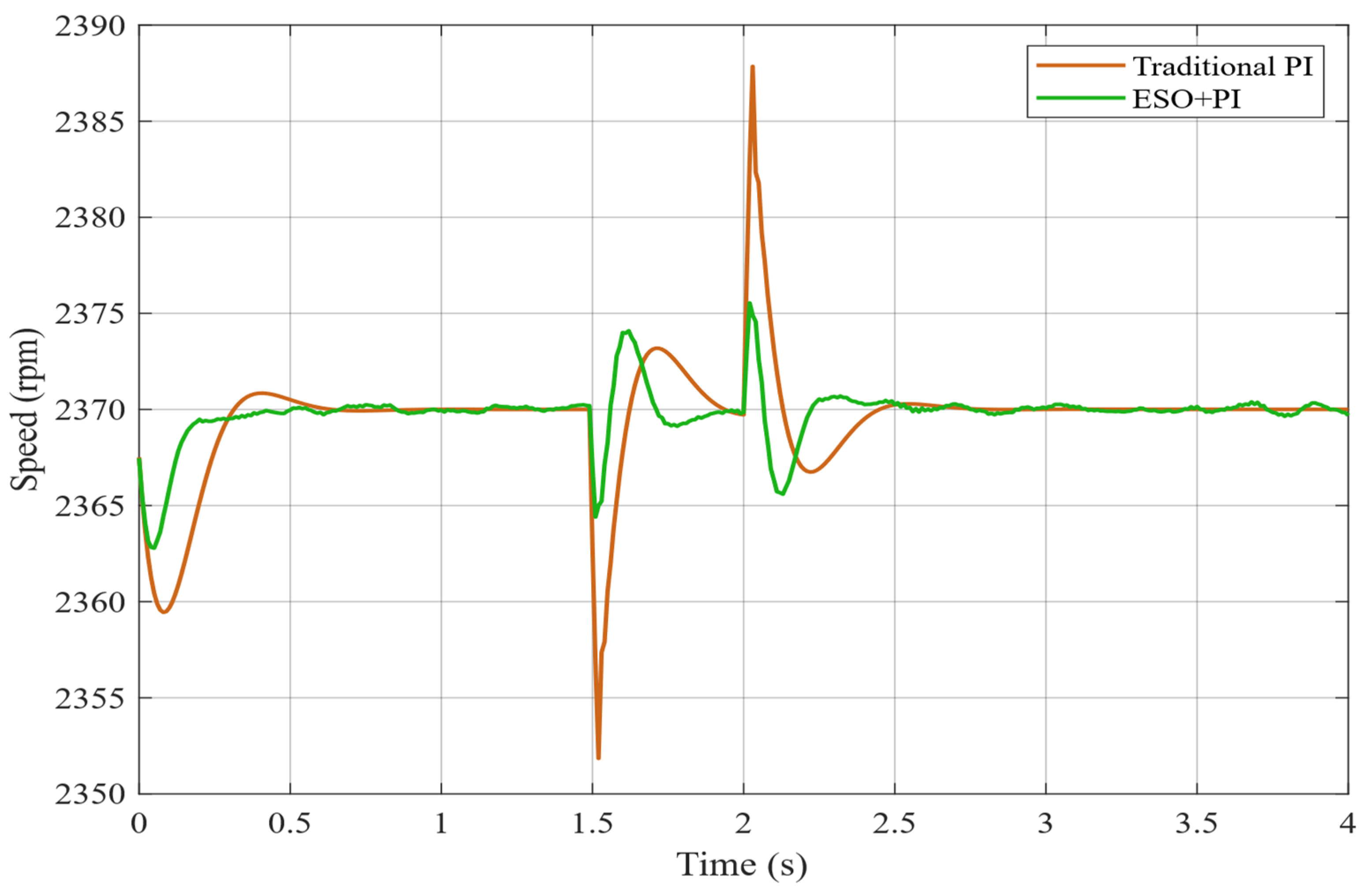
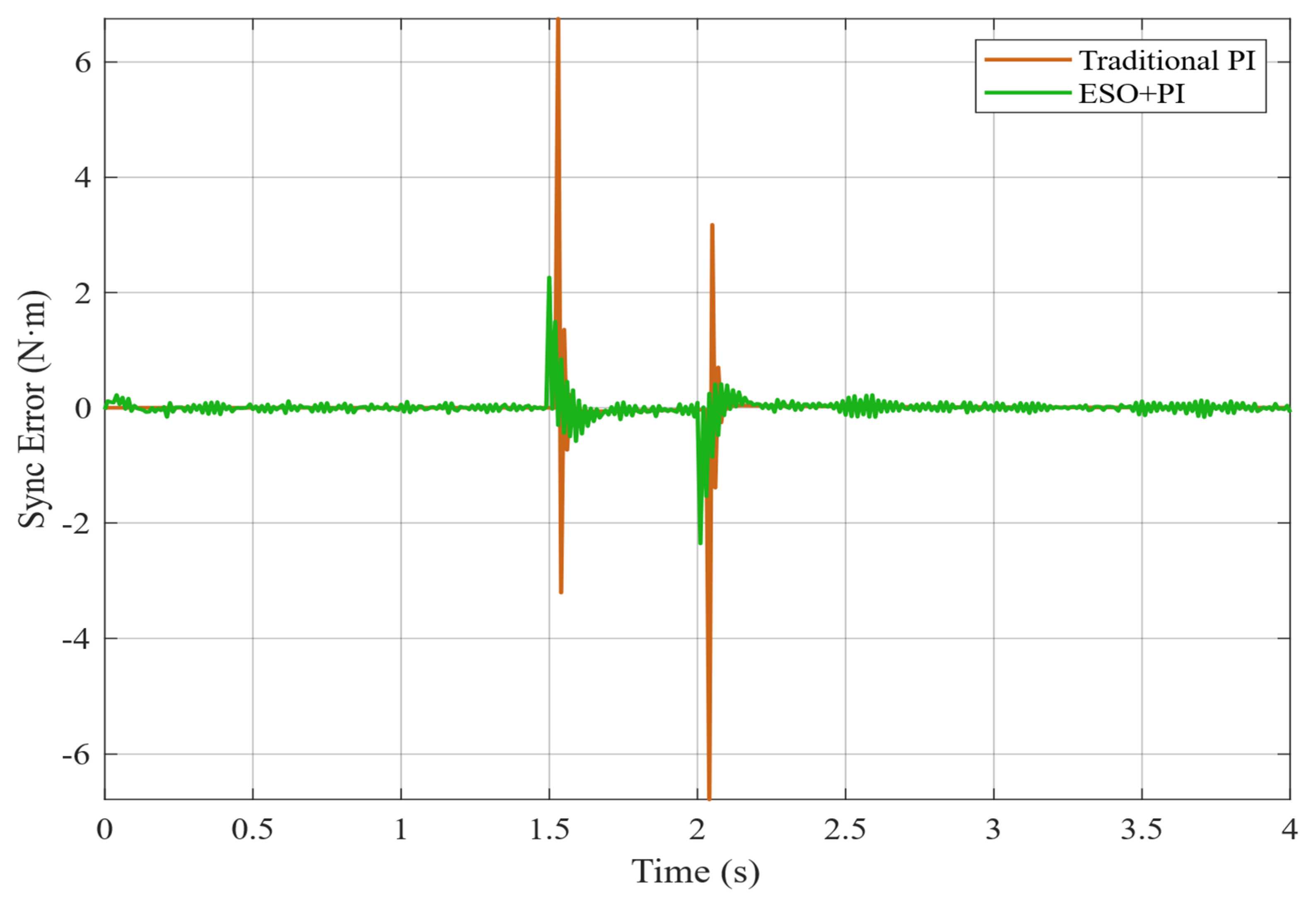
Building upon the aforementioned experiments, a comparative analysis is conducted between ESO and conventional PI control methods. The following conclusions are derived. Figure 10 reveals that the conventional PI approach exhibits a speed drop of 18.2 rpm, requiring over 0.43 s to achieve stability, whereas the ESO method demonstrates a speed drop of merely 5.8 rpm and stabilizes within ±1 rpm in 0.21 s, achieving smooth recovery to the reference value. Figure 11 presents the torque synchronization error comparison, indicating that the conventional PI method exhibits maximum synchronization errors of ±6.8 N·m, while the ESO method maintains maximum synchronization errors within ±2.3 N·m, representing a substantial improvement in synchronization precision.
The simulation results confirm the effectiveness of the proposed ESO-based dual-motor torque synchronization control strategy. Key performance metrics include: ESO response time of 15 ms, system settling time of 0.21 s, and torque synchronization error of 2.3 N·m. These metrics outperform conventional methods, which have an error range of ±6.8 N·m, and substantially enhance dual-motor coordination precision. The system exhibits rapid stability recovery under 15 N·m step load disturbances, demonstrating superior disturbance rejection capabilities. The comprehensive performance comparison is presented in Table 1, showing that the proposed ESO approach significantly outperforms traditional PI control with improvements of 65.4% in torque synchronization accuracy, 62.6% in speed stability, and 51.2% in dynamic response speed.

5. Experiments and Analysis

5.1. Experimental Preparation and Parameter Selection

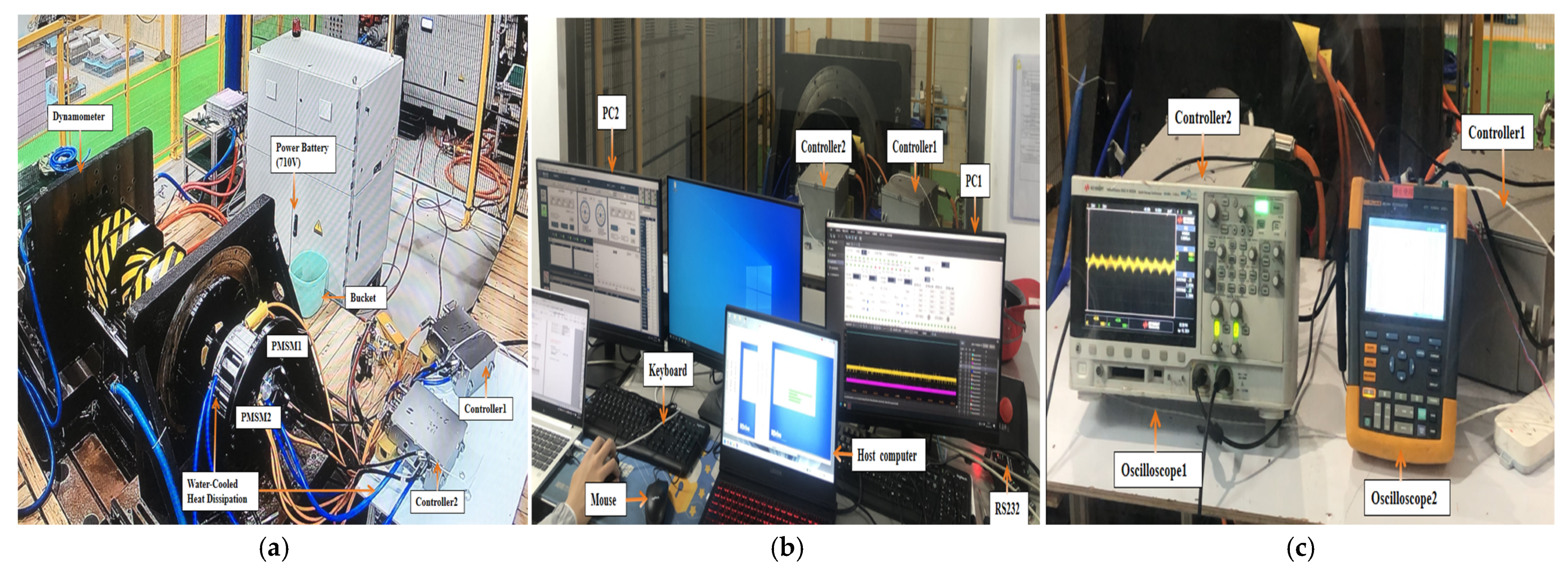
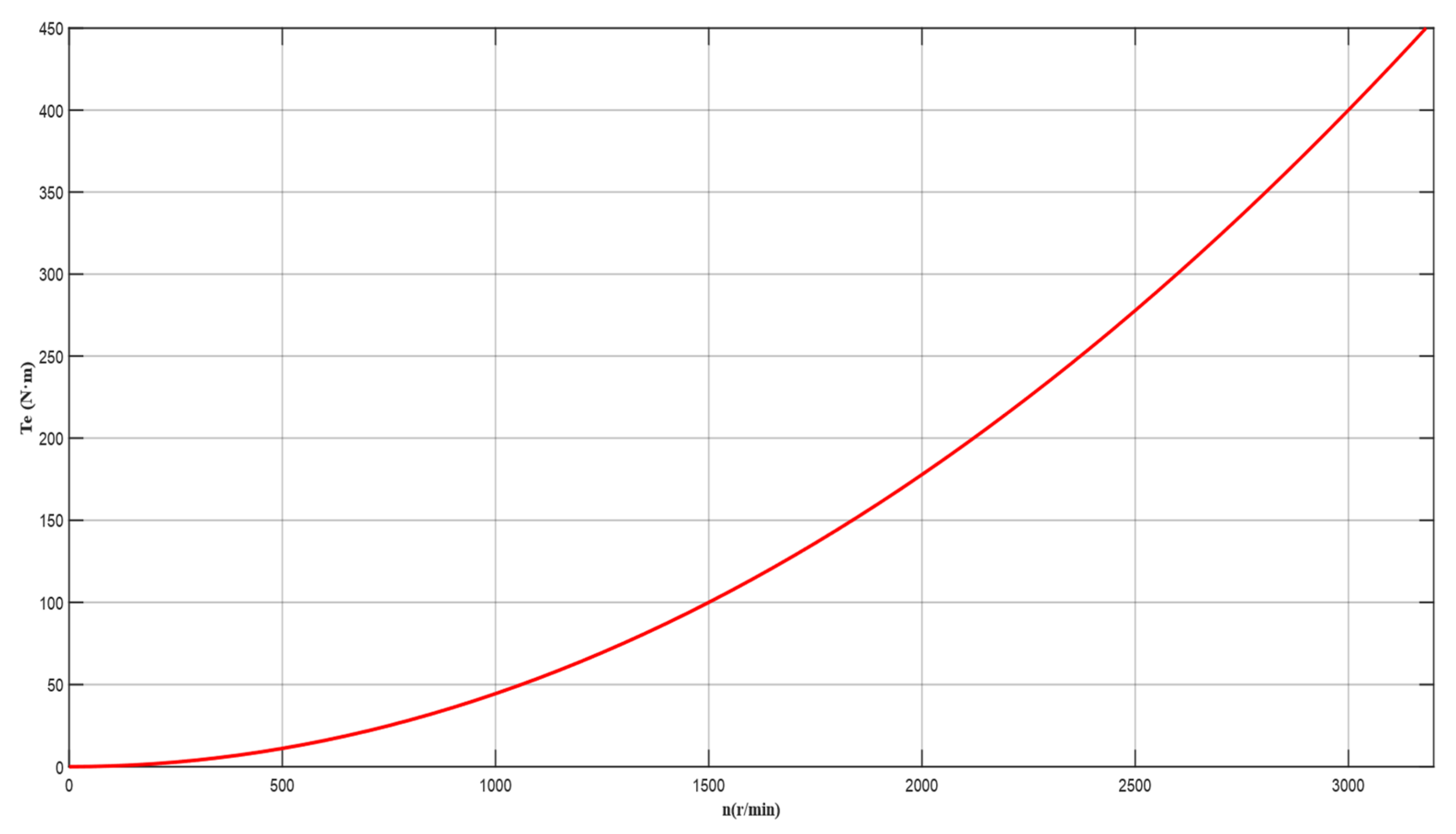
In order to verify the effectiveness of the dual motor synchronous control strategy proposed in this paper, the experimental platform of the dual motor speed control system is constructed, as shown in Figure 12. The drive module consists of a dual permanent magnet synchronous motor configuration connected in series. The control module primarily consists of two motor controllers, a power supply module, conditioning units, and associated circuitry. Motor operating parameters, including rotational speed and current, are displayed via oscilloscopes for real-time monitoring. The key parameters of the PMSM are listed in Table 2. And the relationship between propeller speed and load is shown in Figure 13.

5.2. Experimental Results and Analysis

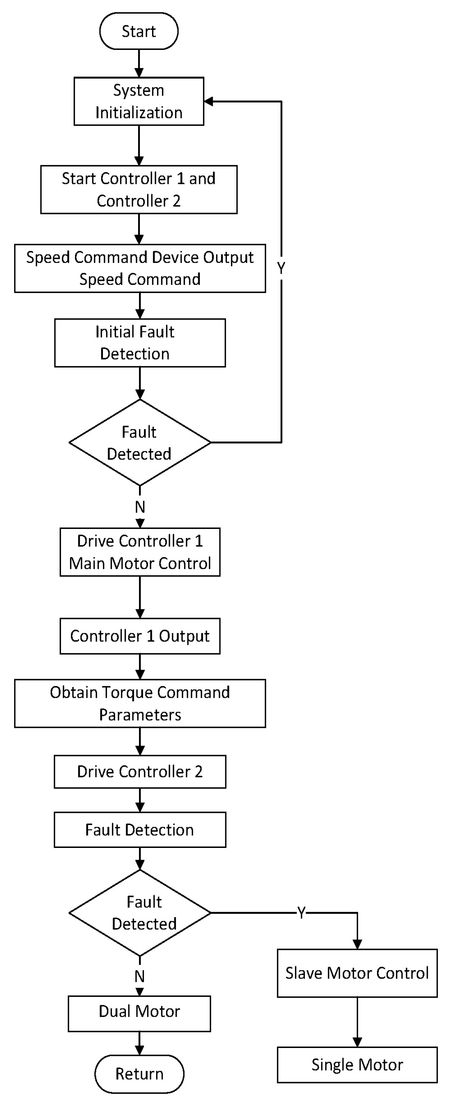
To validate the performance of the dual-redundant electric propulsion system and simulate the actual flight conditions of electric helicopters, a dual-motor, fault-tolerant control experiment was designed. The experimental platform uses a master–slave control architecture. After powering on, the master controller operates in speed mode and the slave controller operates in torque mode. The master controller performs closed-loop speed control using speed information from the upper computer. It also transmits real-time torque information to the slave controller, which executes closed-loop torque control based on the actual torque of the master motor. The experimental parameters were set as follows: a target speed of 2400 rpm and a total system output torque of 240 N·m. Table 3 presents the detailed performance comparison of key system parameters before, during, and after the fault switching process.

5.2.1. Speed Response Characteristics

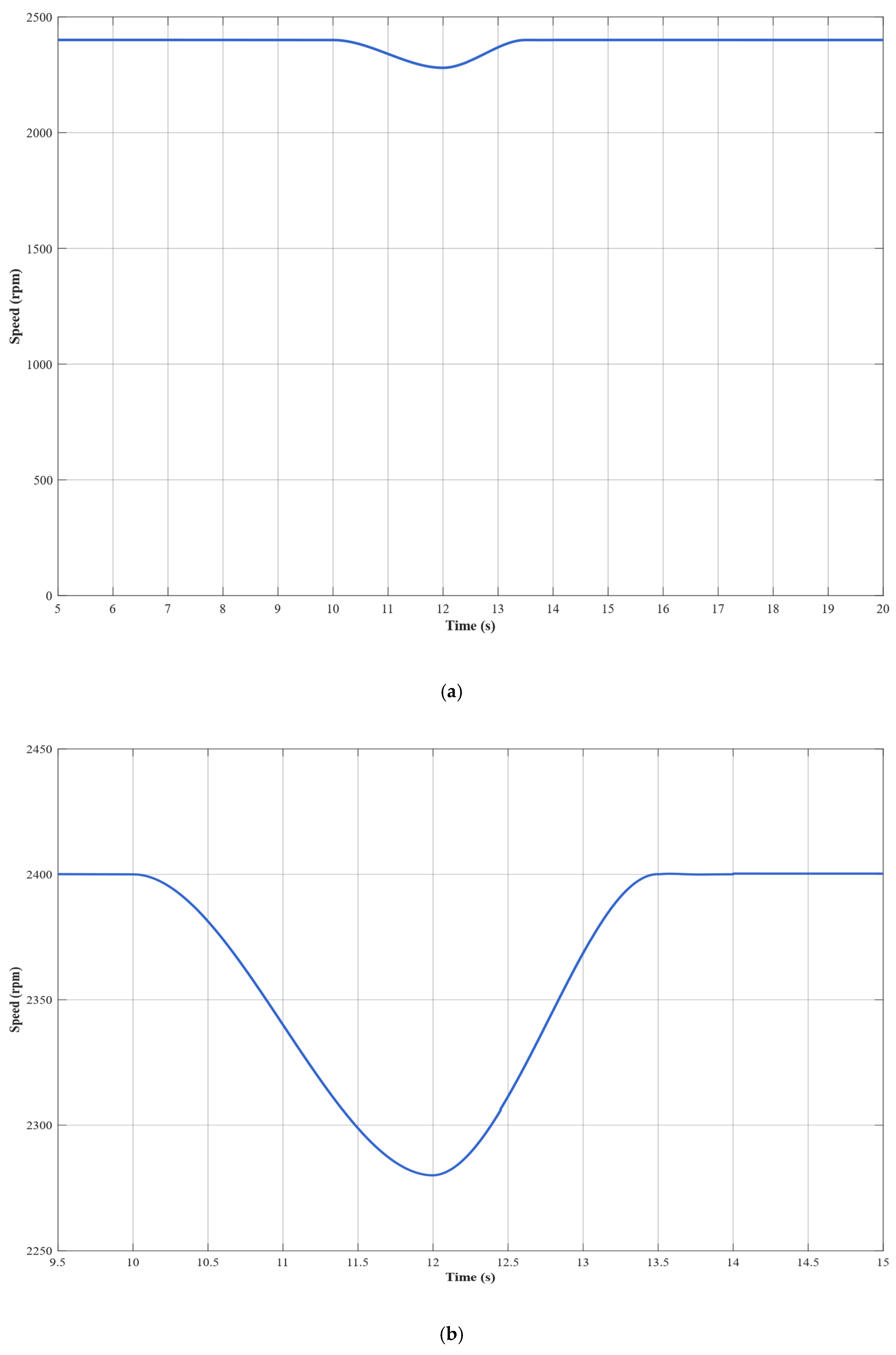
Figure 14 shows the speed response characteristics of the dual-motor system when the master motor stops operating at t = 10.0 s, while the slave motor continues running. The experimental results demonstrate that the system operates stably at 2400 rpm under normal conditions. When the fault occurs at t = 10.0 s, the system speed begins to decline. It reaches a minimum value of 2280 rpm at t = 12 s, which corresponds to a 5% deviation from the setpoint. During the 2 s speed decline phase, the ESO optimizes load estimation accuracy and provides feedforward compensation. The speed recovery phase begins at t = 12 s. During this phase, the PI controller with ESO feedforward compensation effectively regulates the system. The system’s speed is successfully restored to the target value of 2400 rpm within a 1.5 s time window (t = 12–13.5 s). Stable system operation is achieved at t = 13.5 s.

5.2.2. Current Response Characteristics

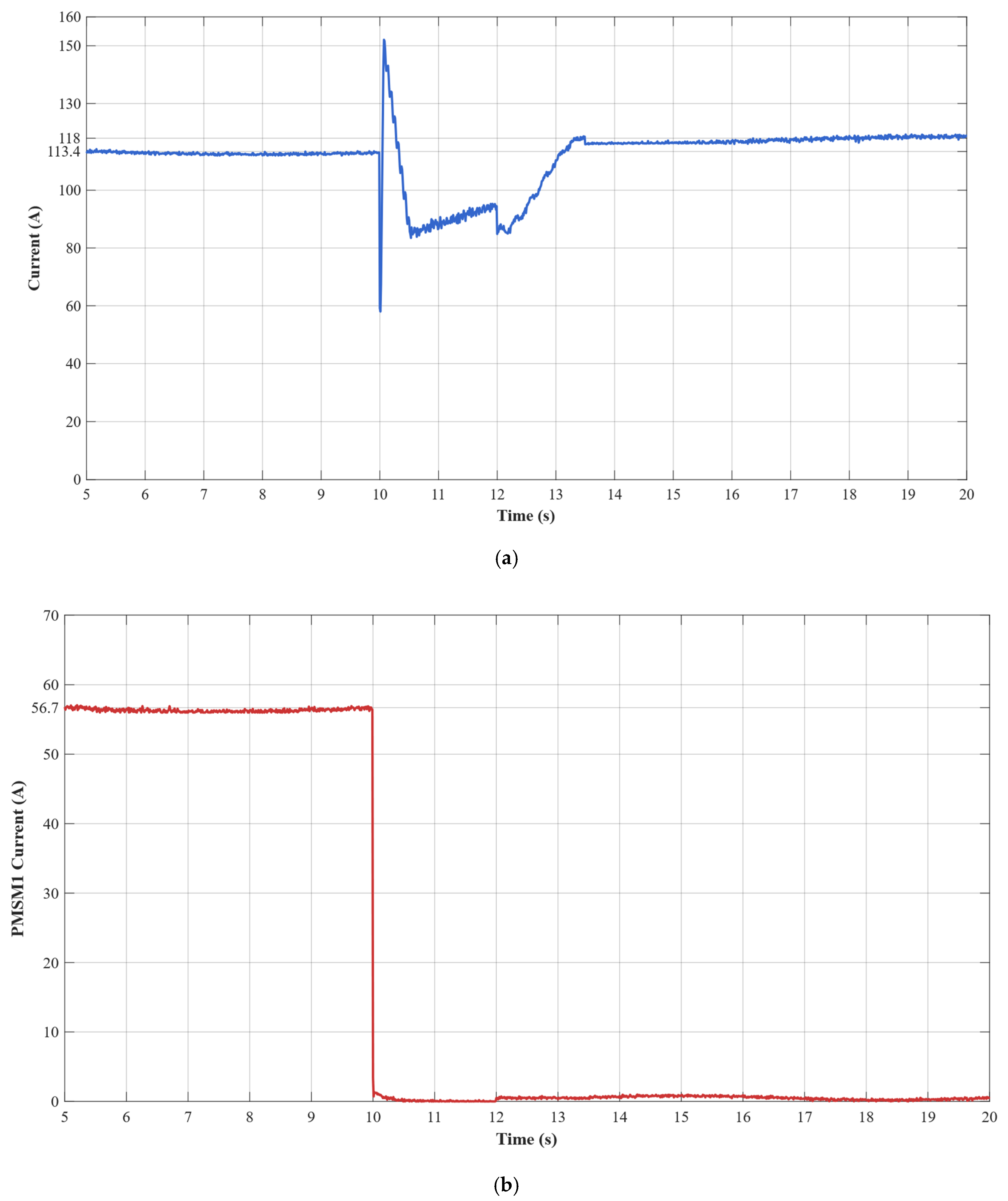
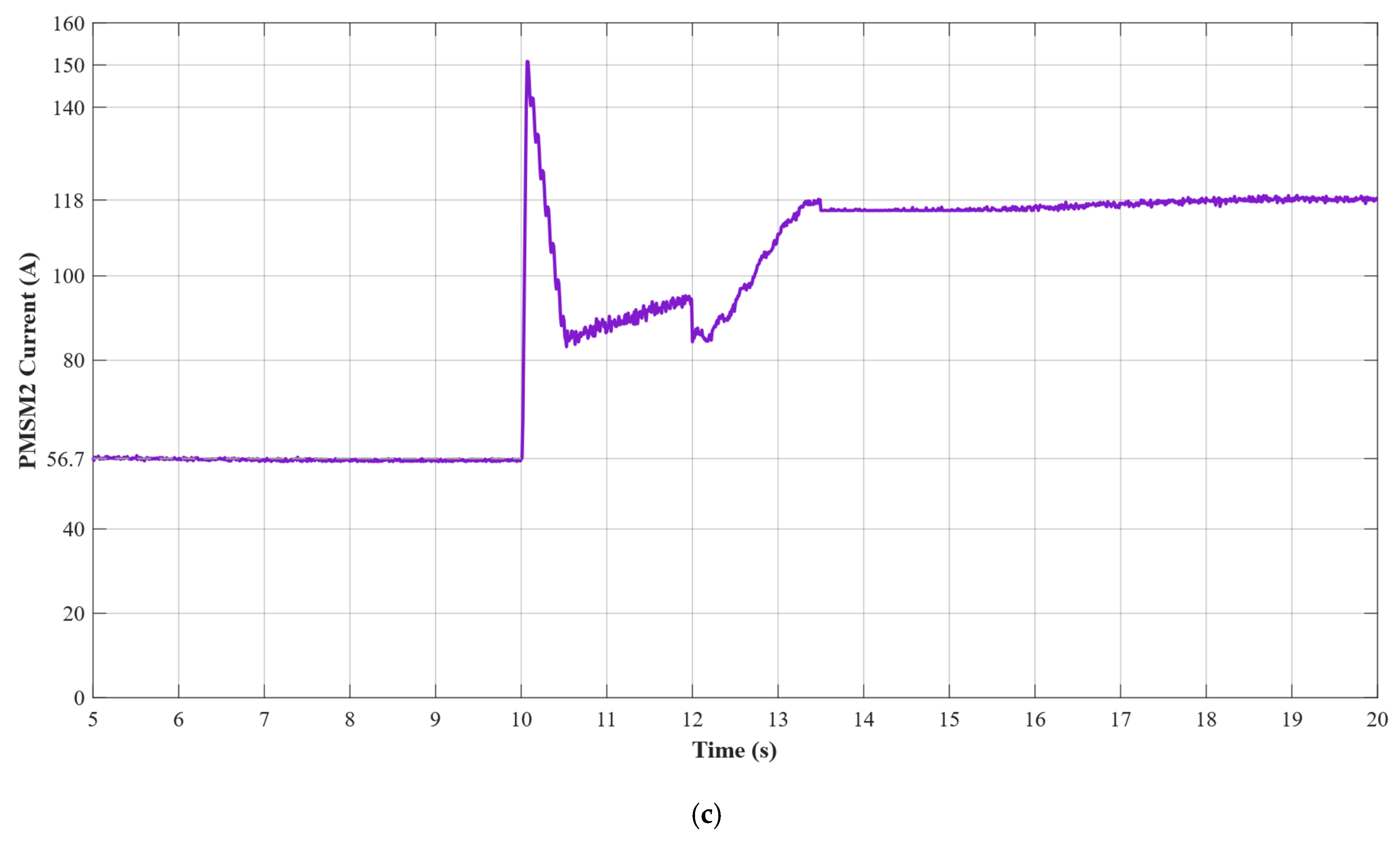
Figure 15 shows the detailed current variation characteristics during the fault switching process. During normal operation, both motors maintain a current of 56.7 A and equally share the system output power, each carrying 120 N·m of torque. At t = 10 s, the current in PMSM 1 instantly drops to zero, and the motor stops. Meanwhile, PMSM 2 experiences a significant transient current overshoot due to a sudden double load. The peak current reaches 150 A, which is equivalent to 2.65 times the normal operating current. After a three-second dynamic adjustment process that considers the control system’s inherent steady-state error and nonlinear factors, PMSM 2′s steady-state current stabilizes at 118 A. This represents a 4% deviation from the theoretical double value of 113.4 A. PMSM 2 successfully carries the entire system output power, achieving single-motor fault-tolerant operation.

5.2.3. Torque Response Analysis

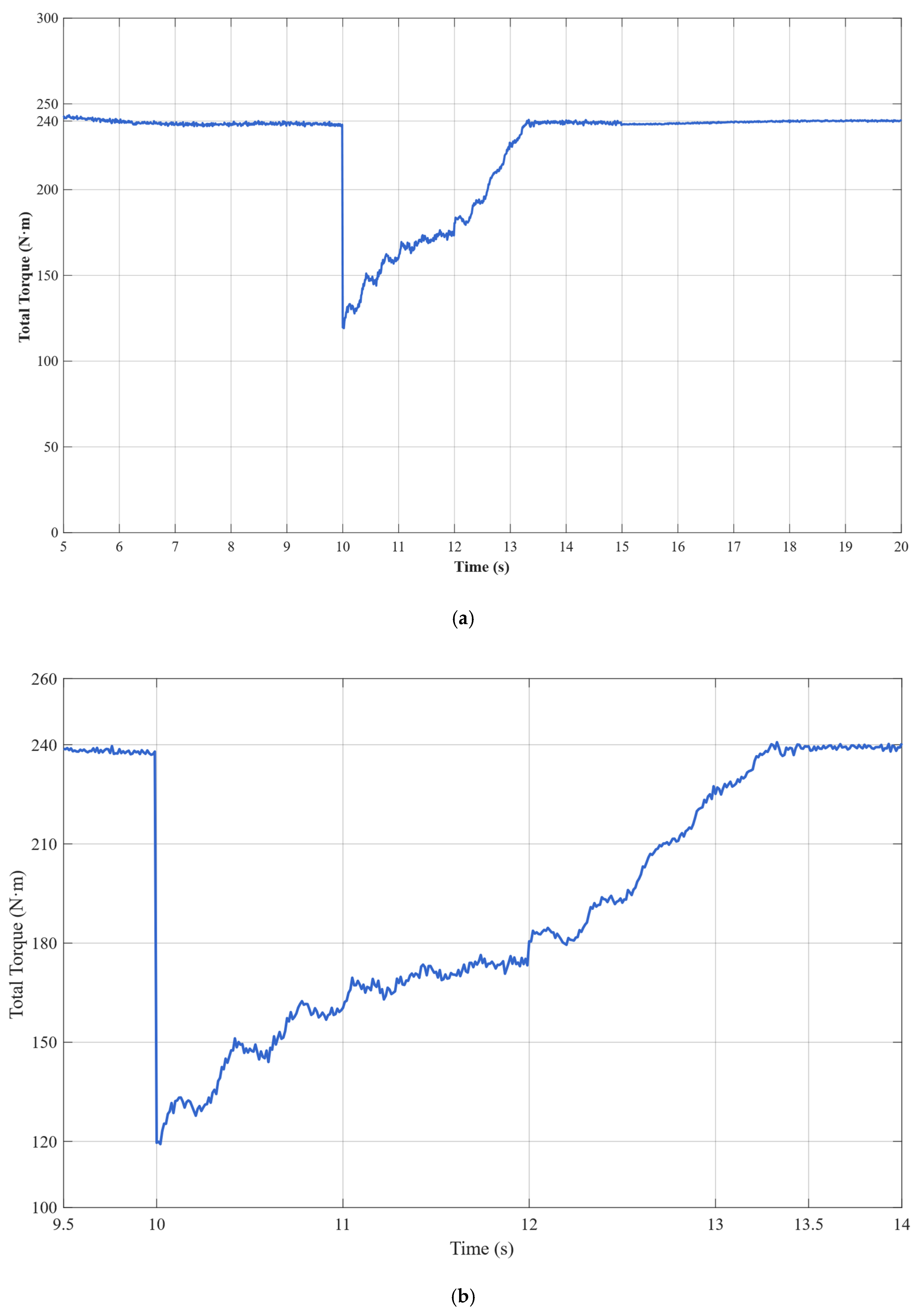
The torque response analysis reveals the detailed dynamics during fault switching. As illustrated in Figure 16, during normal operation, PMSM 1 functions as the master controller in speed mode, providing a stable torque output of 120 N·m and carrying 50% of the system load. The torque fluctuation is controlled within ±1.5 N·m, indicating the speed closed-loop control is stable. At t = 10 s, Controller 1 disconnects to simulate a sudden fault in PMSM 1, causing its torque to instantly drop to 0 N·m and stop. PMSM 2 immediately switches from torque control mode to speed control mode. With ESO feedforward compensation, the torque smoothly increases from 120 N·m to approximately 180 N·m. The PI controller with ESO feedforward compensation precisely regulates the torque, adjusting it from 180 N·m to 240 N·m. This stable, overshoot-free torque regulation process validates the effectiveness of ESO feedforward compensation in suppressing PI controller integral saturation.

5.2.4. ESO + PI Control Performance Validation

The torque response data validates the key technical characteristics of the ESO control algorithm. The ESO’s rapid load estimation capability ensures timely control mode switching. With a detection delay of 15 ms, it meets real-time control requirements. The PI controller achieves smooth torque regulation under ESO feedforward compensation, effectively avoiding the overshoot and oscillation that are common in traditional PI control. During the steady-state phase, the single-motor torque stabilizes at 240 ± 3 N·m. There is slightly increased torque fluctuation compared to normal dual-motor operation due to the increased control difficulty of a single motor carrying a double load. However, it remains within acceptable engineering limits.

5.2.5. System Fault-Tolerant Performance Assessment

The fault switching experiment validates the fault-tolerant capability of the dual-redundant electric propulsion system. Under single-motor fault scenarios, the remaining motor successfully carries the entire 240 N·m system load, achieving a smooth transition from dual-motor to single-motor operation. The key performance indicators under fault conditions are: fault detection time of 15 ms, speed recovery time of 3.5 s, steady-state speed accuracy of ±1 rpm, and steady-state torque accuracy of ±3 N·m. These performance indicators meet the technical requirements of safety-critical applications such as electric helicopters. The complete fault switching control flow chart is shown in Figure 17.

6. Conclusions

To improve the reliability and fault tolerance of electric helicopter flight, this paper presents a dual-redundant electric propulsion system that uses ESO + PI coordinated control. This system uses two relatively independent control systems to power the aircraft and coordinates the operation of the dual motors via a master–slave control architecture. The master controller operates in speed mode, and the slave controller operates in torque mode. The two controllers precisely synchronize through real-time torque information exchange. The system effectively suppresses mechanical coupling interference between the two motors by combining dynamic decoupling control based on an extended state observer with feedforward compensation.
The experimental results demonstrate that the proposed ESO + PI fault-tolerant control strategy performs excellently during critical flight states of electric helicopters. During normal operation, the dual-motor torque synchronization error remains within ±0.5 N·m. Each motor stably outputs 120 N·m of torque at a current of 56.7 A. In the event of a failure in the master motor, the ESO can accurately detect load disturbances within 15 ms with a detection accuracy greater than 95% and rapidly trigger the fault-tolerant control strategy. Upon fault detection, the slave motor immediately switches from torque control mode to speed control mode and assumes the entire system load of 240 N·m.
During the fault switching process, the system speed decreases from 2400 rpm to a minimum of 2280 rpm (5% deviation). Through the coordinated actions of ESO feedforward compensation and PI feedback control, the speed recovers within 3.5 s and ultimately stabilizes at 2400 ± 1 rpm. Current response analysis shows that, at the fault instant, the slave motor experiences a transient current overshoot of 150 A. After 3 s of dynamic adjustment, the current stabilizes at 118 A, with only a 4% deviation from the theoretical value of 113.4 A. Compared to traditional PI control, the ESO + PI method improves torque synchronization accuracy by 65.4%, speed stability by 62.6%, and dynamic response speed by 51.2%.
This study validates the dual-redundant electric propulsion system’s high reliability and rapid fault-tolerance capability under single motor failure conditions. This ensures that the electric helicopter’s power system will not fail during emergencies, providing robust flight safety assurance. All of the system’s key performance indicators meet aviation safety standards: fault detection in 15 ms, fault-tolerant switching in 3.5 s, and steady-state accuracy of ±1 rpm. These results provide important theoretical foundations and technical support for the engineering implementation of safety-critical applications, such as electric helicopters.
Author Contributions

Conceptualization, Z.D. and S.W.; methodology, Z.D.; software, Z.D.; validation, S.W., Z.D. and Q.Z.; formal analysis, S.W.; investigation, S.W.; resources, Q.Z.; data curation, Z.D.; writing—original draft preparation, Z.D.; writing—review and editing, Q.Z.; visualization, Q.Z.; supervision, Q.Z.; project administration, Q.Z.; funding acquisition, S.W. All authors have read and agreed to the published version of the manuscript.

Funding

This research was funded by the Natural Science Foundation of Liaoning Province through the Project under Grant 2022-KF-14-04, and in part by the Natural Science Foundation of Shenyang City through the Project under Grant 23-503-6-03.

Data Availability Statement

The raw data supporting the conclusions of this article will be made available by the authors on request.

Conflicts of Interest

The authors declare no conflicts of interest.

References

  1. Rajini, V.; Nagarajan, V.S.; Kumar, S.B.; Barathkumar, M.; Balaji, R.; Manojshyaam, C.J. Comparative analysis of Synchronous Reluctance Motor with different Permanent Magnet materials. Mater. Today Proc. 2022, 62, 738–745. [Google Scholar] [CrossRef]
  2. Ye, W.; Liu, Y.; Wu, G.; Wu, Q.; Chen, Z.; Chen, Z.; Li, Z.; Cao, Z. Design optimization and manufacture of permanent magnet synchronous motor for new energy vehicle. Energy Rep. 2022, 8, 631–641. [Google Scholar] [CrossRef]
  3. Cho, S.; Lim, J.S.; Oh, Y.J.; Jeong, G.; Kang, D.W.; Lee, J. A study on output characteristics of the spherical multi-DOF motor according to the number of phases and pole pitch angles. IEEE Trans. Magn. 2018, 54, 1–5. [Google Scholar] [CrossRef]
  4. Gitelman, L.; Kozhevnikov, M. Energy Transition Manifesto: A Contribution towards the Discourse on the Specifics Amid Energy Crisis. Energies 2022, 15, 9199. [Google Scholar] [CrossRef]
  5. Zaporozhets, O.; Isaienko, V.; Synylo, K. Trends on current and forecasted aircraft hybrid electric architectures and their impact on environment. Energy 2020, 211, 118814. [Google Scholar] [CrossRef] [PubMed]
  6. Hu, H.; Zha, M.; Chang, L.; Kong, W. Design of Double Redundancy Controller for Electric Actuator Based on Dual three-phase PMSM. In Proceedings of the 2021 IEEE 2nd China International Youth Conference on Electrical Engineering (CIYCEE), Chengdu, China, 15–17 December 2021; IEEE: Piscataway, NJ, USA, 2021; pp. 1–6. [Google Scholar]
  7. Rathod, K.; Mija, S.J. Robust Control of 2-DoF Helicopter System in Presence of Unmatched Disturbances & Actuator Faults. In Proceedings of the 2022 2nd International Conference on Intelligent Technologies (CONIT), Hubli, India, 24–26 June 2022; pp. 1–7. [Google Scholar]
  8. Zhang, C.; Niu, M.; He, J.; Zhao, K.; Wu, H.; Zhang, M. Robust synchronous control of multi-motor integrated with artificial potential field and sliding mode variable structure. IEEE Access 2017, 5, 197–207. [Google Scholar] [CrossRef]
  9. Koren, Y. Cross-coupled biaxial computer control for manufacturing systems. J. Dyn. Syst. Meas. Control 1980, 102, 265–272. [Google Scholar] [CrossRef]
  10. Sun, G.; Mao, Y.; Li, X.; Ni, Y. Dual-motor master-slave cross-coupling synchronization control of winch considering parameters variations. In Proceedings of the IECON 2020 the 46th Annual Conference of the IEEE Industrial Electronics Society, Singapore, 18–21 October 2020; IEEE: Piscataway, NJ, USA, 2020; pp. 199–204. [Google Scholar]
  11. Qu, L.; Qiao, W.; Qu, L. An extended-state-observer-based sliding-mode speed control for permanent-magnet synchronous motors. IEEE J. Emerg. Sel. Top. Power Electron. 2020, 9, 1605–1613. [Google Scholar] [CrossRef]
  12. Liu, B. Speed control for permanent magnet synchronous motor based on an improved extended state observer. Adv. Mech. Eng. 2018, 10, 1687814017747663. [Google Scholar] [CrossRef]
  13. Shao, D.; Huang, Y. Parameter Identification of Permanent Magnet Synchronous Motor Based on Multi-innovation Least Square Method. In Proceedings of the 2020 IEEE 9th Joint International Information Technology and Artificial Intelligence Conference (ITAIC), Chongqing, China, 11–13 December 2020; IEEE: Piscataway, NJ, USA, 2020; Volume 9, pp. 1810–1814. [Google Scholar]
  14. Brosch, A.; Hanke, S.; Wallscheid, O.; Böcker, J. Data-driven recursive least squares estimation for model predictive current control of permanent magnet synchronous motors. IEEE Trans. Power Electron. 2020, 36, 2179–2190. [Google Scholar] [CrossRef]
  15. Zhang, Q. Current Harmonic Suppression Strategy of Dual Three-phase PMSM Based on LESO. In Proceedings of the 2022 IEEE 5th Advanced Information Management, Communicates, Electronic and Automation Control Conference (IMCEC), Chongqing, China, 16–18 December 2022; Volume 5, pp. 390–394. [Google Scholar]
  16. Madoński, R.; Herman, P. Survey on methods of increasing the efficiency of extended state disturbance observers. ISA Trans. 2015, 56, 18–27. [Google Scholar] [CrossRef] [PubMed]
  17. Nahri, S.N.F.; Du, S.; van Wyk, B.J. Predictive extended state observer-based active disturbance rejection control for systems with time delay. Machines 2023, 11, 144. [Google Scholar] [CrossRef]
  18. Alves, E.F.; Nϕland, J.K.; Marafioti, G.; Mathisen, G. Online parameter identification of synchronous machines using Kalman filter and recursive least squares. In Proceedings of the IECON 2019-45th Annual Conference of the IEEE Industrial Electronics Society, Lisbon, Portugal, 14–17 October 2019; IEEE: Piscataway, NJ, USA, 2019; Volume 1, pp. 7121–7128. [Google Scholar]
  19. Chen, W.; Wu, Y.; Du, R.; Chen, Q.; Wu, X. Speed Tracking and Synchronization of a Dual-Motor System via Second Order Sliding Mode Control. Math. Probl. Eng. 2013, 2013, 919837. [Google Scholar] [CrossRef]
Figure 1. Electric helicopter’s electric propulsion system.
Aerospace 12 00847 g001
Figure 2. Electric aircraft propulsion system.
Aerospace 12 00847 g002
Figure 3. The control schematic diagram of PMSM 1.
Aerospace 12 00847 g003
Figure 4. The control schematic diagram of PMSM 2.
Aerospace 12 00847 g004
Figure 5. Step load disturbance.
Aerospace 12 00847 g005
Figure 6. Speed under step load disturbance.
Aerospace 12 00847 g006
Figure 7. ESO torque estimation under step load disturbance.
Aerospace 12 00847 g007
Figure 8. (a) Torque synchronization error; (b) ESO estimation error.
Aerospace 12 00847 g008
Figure 9. (a) Analysis of q-axis current; (b) Analysis of d-axis current.
Aerospace 12 00847 g009
Figure 10. Comparison of traditional PI and ESO speed performance.
Aerospace 12 00847 g010
Figure 11. Comparison of Torque Synchronization Errors between Traditional PI and ESO.
Aerospace 12 00847 g011
Figure 12. Dual-motor control system experimental platform: (a) experimental platform; (b) mainframe monitor system; (c) measuring apparatus.
Aerospace 12 00847 g012
Figure 13. Relationship between propeller speed and load.
Aerospace 12 00847 g013
Figure 14. (a) Overall speed response during fault switching; (b) Magnified view of speed drop and recovery phase.
Aerospace 12 00847 g014
Figure 15. Total Phase Current (a); PMSM1 Phase Current (b); PMSM2 Phase Current (c).
Aerospace 12 00847 g015aAerospace 12 00847 g015b
Figure 16. (a) Overall torque response during fault switching; (b) Detailed torque dynamics during fault transition.
Aerospace 12 00847 g016
Figure 17. Fault switching torque.
Aerospace 12 00847 g017
Table 1. Hovering performance indicators.
Performance IndicatorsTraditional PI ControlESO + PI ControlImprovement Margin
Speed Stability18.2 rpm5.8 rpm62.6%
Torque Synchronization Error6.8 N·m2.3 N·m65.4%
Dynamic Response Time0.43 s0.21 s51.2%
Table 2. Parameters of PMSM.
SymbolQuantityValue
L d Inductance of d axis0.292 mH
L q Inductance of q axis0.273 mH
ψ Rotor magnetic flux0.1014 Wb
R Stator resistance22.9 mΩ
J Rotor inertia0.0922 kg·m2
B Viscous friction coefficient0.0105 N·m·s
P Number of pole pairs10
Table 3. Key parameters comparison of dual-motor system during fault switching.
System ParametersBefore Fault (t < 10 s)Fault Transient (10–13.5 s)After Fault Stabilization (t > 13.5 s)
PMSM 1Speed ControlFault ShutdownShutdown
PMSM 2Torque ControlSwitch to Speed ControlSpeed Control
Speed24002400 → 2280 → 24002400
PMSM 1 Current (A)56.756.7 → 00
PMSM 2 Current (A)56.756.7 → 150 → 118118
PMSM 1 Torque (N·m)120120 → 00
PMSM 2 Torque (N·m)120120 → 240240
Power Distribution50% + 50% 100% (PMSM 2)
Disclaimer/Publisher’s Note: The statements, opinions and data contained in all publications are solely those of the individual author(s) and contributor(s) and not of MDPI and/or the editor(s). MDPI and/or the editor(s) disclaim responsibility for any injury to people or property resulting from any ideas, methods, instructions or products referred to in the content.