1. Introduction
The geostationary orbit has zero orbital eccentricity and zero orbital inclination. The motion period of space targets in this orbit is the same as the rotation period of the Earth. Since the subsatellite track of objects moving in the geostationary orbit is a point, high-value communication satellites and meteorological satellites mostly use the geostationary orbit [
1,
2]. Therefore, it is necessary to detect objects in the geostationary orbit to ensure operational safety [
3].
At present, large field-of-view optical telescopes are one of the main means for detecting geostationary orbit targets. These devices are low-cost and highly efficient. However, large field-of-view telescopes have problems such as dim target images and a multitude of stars within the field of view. Additionally, noise and stray light interference are severe. These issues complicate detection.
Therefore, under normal circumstances, it is necessary to suppress stars first before detecting targets. Deval Samirbhai Mehta et al. proposed a star-suppression technique based on Rotation-Invariant Additive Vector Sequence. By combining the additive property of vectors with a rotation-invariant framework, this technique can effectively solve the problems of star-point missing and false-star interference [
4]. Lei Zhang et al. addressed the issue that existing star suppression algorithms struggle to effectively handle faint stars. They proposed a new star suppression method based on recursive moving target indication (RMTI), aiming to improve the accuracy of space target detection [
5]. Dan Liu et al. proposed a high-precision and low-computation-cost space target detection method based on the dynamic programming sliding window method (DPSWM). This method employs the minimum enclosing rectangle approach to calculate the aspect ratios of the minimum enclosing rectangles of stars and space targets in image sequences. By utilizing the differences in this ratio between the two, stars can be removed. The method can effectively detect faint space targets in large-field surveillance with long exposure times [
6]. Huan N. Do et al. proposed a robust pipeline named GP-ICP, integrating Gaussian Process Regression (GPR) and Trimmed Iterative Closest Point (T-ICP). For image registration, T-ICP is adopted to estimate homographies by minimizing trimmed residual sums, excluding outliers to align stars accurately across frames. Finally, star removal and line-based track verification identify true GEO objects [
7].
However, as the field of view of the telescope expands, the number of stars in the image increases dramatically, rendering traditional star suppression methods increasingly inadequate. This inadequacy stems from two critical issues caused by the surge in star count, which can be clearly illustrated by comparing a large FoV (10° × 10°) with a small FoV (1° × 1°) based on our actual measurements:
Our experimental statistics show that a 1° × 1° FoV contains approximately 60 stars (for magnitudes ≤ 14, consistent with the sensitivity of our optical system).In contrast, a 10° × 10° FoV (100 times the area) contains about 7000 stars—over 116 times more than the small FoV. This exponential growth directly challenges the feasibility of traditional methods in two aspects:
First, computational efficiency collapses under the massive star count. Traditional methods such as the rotation-invariant additive vector sequence and dynamic programming sliding window rely on pairwise feature matching. In 1° × 1° FoV, these methods process a frame in ~0.8 s consistent with, [
4,
6]; but in 10° × 10° FoV (7000 stars), the same algorithms require ~700 s per frame in our tests. This is over 875 times slower and far exceeds the real-time requirement for operational detection systems.
Second, the uniqueness of features used in traditional matching is severely compromised. In 1° × 1° FoV, features like the aspect ratio of the minimum enclosing rectangle or rotation-invariant vectors are distinct enough to keep the mismatch rate below 4%. However, in 10° × 10° FoV, the sheer number of stars leads to widespread feature overlap: our analysis of 150 real 10° × 10° frames shows that 58% of stars share nearly identical aspect ratios (vs. 3% in 1° × 1° frames), and 51% of stars have indistinguishable vector sequences (vs. <1% in small FoV). This directly causes critical failures: false suppression (stars misidentified as targets) increases from 3% to 42%, and missed suppression (targets misidentified as stars) rises from <1% to 35% in comparative tests using the RMTI method and rotation-invariant vector method. Faced with these challenges in large field of view scenarios, some scholars have turned to image stacking methods as an alternative solution.
Hao Luo et al. proposed a multi-frame short-exposure stacking mode to detect geostationary orbit targets. They registered the collected multi-frame images and adopted mean stacking, which effectively improved the target detection capability [
8]. Zheng Haizhu et al. proposed a short-exposure stacking observation mode based on a high-frame-rate astronomical CMOS camera, which can perform high-precision observations on Resident Space Objects. By conducting mean stacking on multiple frames of images, high-precision astronomical positioning of space targets is achieved [
9].
Yanagisawa, T et al. proposed a stacking method for detecting small debris in the Geostationary Orbit. The core of this method is to stack multiple images taken by a CCD camera using the median-value operation, which can eliminate star trails and reduce the background noise, thereby enabling the detection of faint debris that is invisible in a single image [
10]. Sun Rongyu et al. adopted mathematical morphology operators to eliminate noise. They then conducted median stacking on the continuous frames to remove the influence of field stars, thereby achieving automatic detection of GEO targets [
11]. Barak Zackay et al. proposed an optimized coaddition method. This approach first applies a matched filter to each individual image using its own point spread function (PSF), then sums the filtered images with appropriate weights. This method boosts the survey speed of deep ground-based imaging surveys. However, it depends on accurate PSF estimation and is sensitive to outliers [
12].
Quan Sun et al. proposed a star suppression method based on enhanced dilation difference. Utilizing inter-frame correlation, this method performs differencing on registered images to extract targets, but it may lose targets near stars after processing [
13]. Liu Feng et al. proposed a detection algorithm based on triangle matching and maximum projection transformation, which can effectively suppress stationary stars and extract target motion trajectories [
14]. Xuguang Zhang et al. put forward a method for detecting dim space targets based on maximum value stacking. By conducting maximum value stacking on multi-frame images after star registration, space targets form trajectory streaks. Then the trajectories are mapped back to single-frame images according to pixel frame indices, enabling accurate target positioning [
15].
Currently, stacking methods are the main approach for detecting geostationary orbit targets. Two specific techniques are commonly used: mean stacking and median stacking. Mean stacking involves summing the pixel values of multiple images to enhance the target signal. Since noise is random and does not add up precisely, this method can significantly improve the signal-to-noise ratio (SNR). However, it also results in the stars in the field of view forming trails that can obscure the target, making it challenging to detect point-like targets among numerous stellar streaks [
16,
17]. The median stacking method takes the median value of pixels from multiple frames as the final result. While it can handle star occlusion, when processing images with non-uniform backgrounds, it may lead to localized noise concentration, resulting in a large number of false alarms. In addition, median projection requires star registration of images and streak detection algorithms. Jenni Virtanen et al. designed a comprehensive streak detection and analysis pipeline tailored for space debris observations. This pipeline addresses the challenges of detecting long, curved, and low-SNR streaks in single images [
18]. A. Vananti et al. proposed an improved faint streak detection method based on a streak-like spatial filter, which enhances the signal of streak-shaped targets by matching the geometric morphology of the filter to that of the streaks, enabling the detection of extremely faint streaks. However, these methods are difficult to meet the real-time requirements [
19].
Existing stacking methods for GEO detection have three key limitations. Mean stacking produces star trails that obscure point targets; Median stacking leads to high false alarms in non-uniform backgrounds (e.g., moonlight stray light or cloud); Most methods require streak detection, which increases computational complexity. To address these gaps, this paper proposes a geostationary orbit target detection method based on minimum value stacking. By extracting the minimum value at the pixel position from multiple frames, it eliminates the need for image registration, can effectively deal with star occlusion, and realizes the rapid detection of geostationary orbit targets in images.
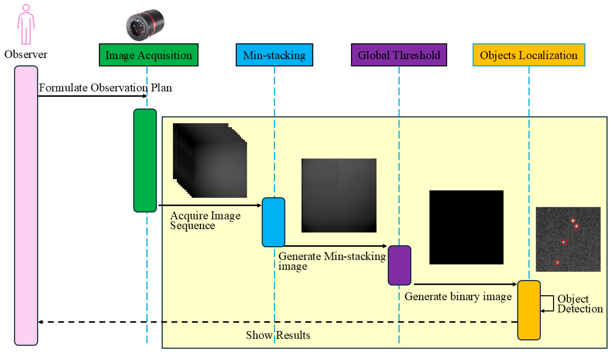
In this paper, we first analyze the apparent motion of stars and geostationary orbit targets, which serves as the theoretical foundation for the algorithm. Subsequently, the specific procedures of the method are introduced, including min-stacking, adaptive threshold segmentation, and target localization. Finally, the algorithm’s performance is evaluated based on real images in terms of detection rate, false alarm rate, and detection speed.
2. Target Apparent Motion Analysis
This paper is based on the theoretical foundation of differences in Apparent Motion. These differences are observed between stars and geostationary orbit satellites under telescope stare mode. Target apparent motion refers to the speed at which targets move within the field of view. This is typically measured in pixels per second. By leveraging the relationship between the angular velocity
of the target and the telescope’s angular resolution
, we can derive the target’s movement speed
in the pixel coordinate system.
Here,
represents the angular resolution of the telescope. It refers to the smallest angle that the telescope can distinguish. The calculation formula is as follows:
Here,
represents the field-of-view angle of the telescope,
denotes the pixel size of the target surface,
indicates the size of the telescope’s CCD target surface, and
represents the focal length of the telescope. Thus, for a target, its visual motion within the telescope’s field of view is fundamentally determined by its angular velocity
relative to the telescope.
For stars, since they are located infinitely far from Earth, even the nearest stars are about ten orders of magnitude larger than Earth’s radius. Therefore, in the Earth-centered inertial (ECI) coordinate system, stars can be considered stationary. A Stare-Mode telescope on the Earth’s surface can be regarded as rotating uniformly around the Earth’s axis at the Earth’s rotational angular velocity of approximately 15 arcseconds per second (as/s). From the principle of relative motion, stars should appear to move at a certain speed within the telescope’s field of view. Suppose the geographic latitude and longitude of the telescope are
, and the right ascension and declination of the star in the ECI coordinate system are
. Since stars are very distant, the local horizontal coordinate system can be considered coincident with the ECI system. Using the transformation relations between the second equatorial coordinate system and the first equatorial coordinate system, we can obtain the hour angle and declination of the star in the local hour angle coordinate system, denoted as
.
Here,
represents the sidereal time at the observation station, and
denotes the Earth’s rotational speed. We can further derive the transformation relationship between the hour angle coordinates and the horizontal coordinates (with the north point as the principal point).
Thus,
represents the horizontal coordinates of the star, and
represents the hour angle coordinates of the star.
and
are the direction cosines based on the Euler angle rotations.
Assuming that the star is located on a unit sphere with the telescope as the center and a radius of 1. According to the transformation relationship between spherical coordinates and rectangular coordinates, we can derive that:
Differentiating with respect to
yields the velocity of the stars in the horizontal coordinate system.
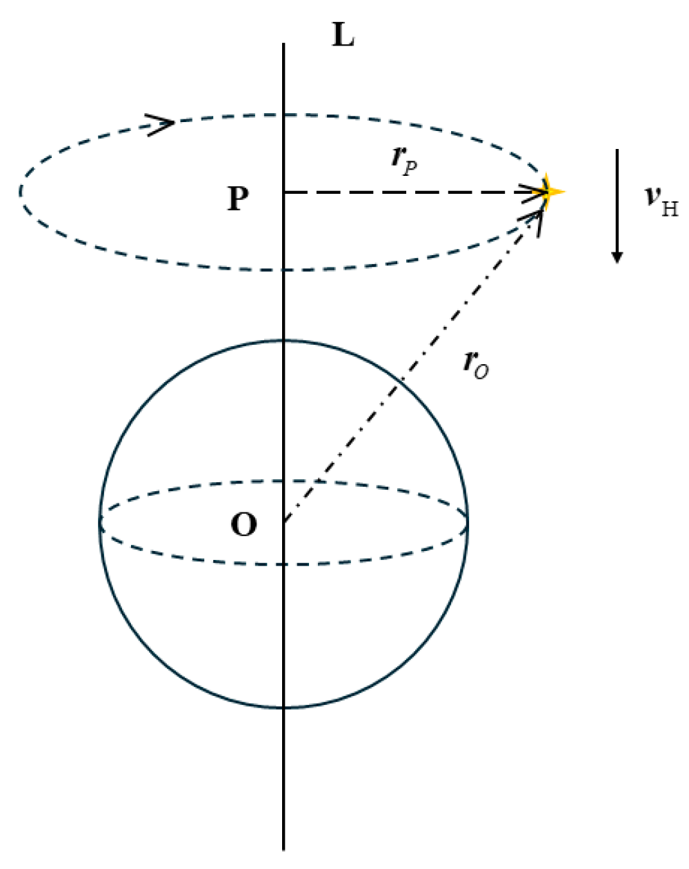
When the Earth is rotating uniformly about the celestial axis with angular velocity
, stars appear to rotate uniformly about the celestial axis in Earth-fixed coordinate system. Their velocity
is the circumferential velocity in the horizontal coordinate system, as shown in
Figure 1.
Let the celestial axis be L, and the star’s perpendicular line intersects the celestial axis at point P. The vector from point P to the star is
, and the position vector from the geocenter to the star is
. The geocenter lies on the celestial axis. Since
,
then
. Therefore,
can be regarded as the linear velocity of the star rotating around the geocenter with angular velocity
at this moment. Since the star is sufficiently distant, the effect of the positional difference between the geocenter and the station center can be neglected. Therefore,
, then
. That is,
can be considered as the linear velocity of the star’s motion around the station center in the horizontal coordinate system, and
can be regarded as the angular velocity of the star’s motion around the station center. Hence,
By substituting Equation (11) into Equation (12), the magnitude of the angular velocity is obtained.
It follows that the angular velocity of a star in the horizontal coordinate system is determined solely by the Earth’s rotational angular velocity and the star’s own declination. The viewing angle of a stare-mode telescope is fixed relative to the Earth. So the horizontal coordinate system is at rest relative to the camera coordinate system. Therefore, the magnitudes of the angular velocities of the stars in both the horizontal and camera coordinate systems are equal, which means
.
This means that the magnitude of the angular velocity of the stars in the field of view is determined by the declination of the telescope’s pointing. The range of values is between 0 and the Earth’s rotational angular velocity. When the telescope points directly at the north or south celestial poles, the motion velocity of the stars in the field of view is zero. When the telescope points at the celestial equator, the angular velocity of the stars in the field of view is equal to the Earth’s rotational angular velocity.
The motion differences among stars at different latitudes within the same field of view are not considered, and the influence of the projection transformation on the motion speed of the stars is also ignored. By ignoring these two factors, the magnitude of the motion speed of the stars in the pixel coordinate system of the image is obtained
For geostationary orbit targets, we adopt the Earth-Centered Earth-Fixed (ECEF) coordinate system as the reference frame. In this coordinate system, the position coordinates of the geostationary orbit target are denoted as
, which is a fixed and unchanging value. This indicates that during its on-orbit operation, the target does not experience any positional change relative to the ECEF coordinate system. Similarly, the coordinates of the observation station are set as
, and this set of coordinates is also constant, reflecting that the observation station is in a stationary state relative to the ECEF coordinate system.
Since both the geostationary orbit target and the observation station are in a stationary state within the Earth-Centered Earth-Fixed coordinate system, the relative velocity between them is 0. That is to say, the geostationary orbit target remains stationary in the coordinate system of the observation station. Moreover, as the coordinate system of the observation station and the coordinate system of the camera maintain relative rest, the geostationary orbit satellite is stationary in the camera coordinate system, which means it is motionless in the pixel coordinate system.
In the actual space environment, geostationary orbit targets are affected by factors such as the perturbation of the Earth’s non-spherical gravitational field and solar radiation pressure. As a result, their sub-satellite point positions are not absolutely stationary but exhibit slight drifts. To clarify the actual motion state of satellites in observed images, this paper quantitatively analyzes the drift amplitude through simulation experiments.
In the experiment, the longitude and latitude data of the GEO satellite’s sub-satellite point were collected at 1-min intervals. Continuous monitoring results showed that the satellite’s sub-satellite point drifts by approximately 0.001° (i.e., 3.6 arcsec) in the longitude direction every 53 min (3180 s). This drift phenomenon stems from the long-term perturbation effect caused by the non-spherical nature of the Earth’s gravitational field. It is also consistent with the perturbation laws in the orbital dynamics theory of GEO targets.
Furthermore, our simulation results are in good agreement with the findings in Reference [
20], where the authors reported a position offset of approximately 10 km for GEO satellites in 24-h forecasts under the influence of Earth’s non-spherical perturbations. Converting this linear displacement to angular drift, the 10 km daily offset corresponds to an angular displacement of approximately 57.66 arcseconds per day, which equals 2.4 arcseconds per hour. This aligns closely with our simulation results—our measurements show a longitudinal drift of 3.6 arcseconds over 53 min (equivalent to ~4.1 arcseconds per hour), considering that our analysis incorporates both gravitational perturbations and solar radiation pressure effects. The slight difference can be attributed to the different observation time scales: our analysis focuses on short-term (several hours) drift characteristics with multiple perturbation sources, while Reference [
20] presents long-term (24-h) cumulative effects primarily from gravitational perturbations.
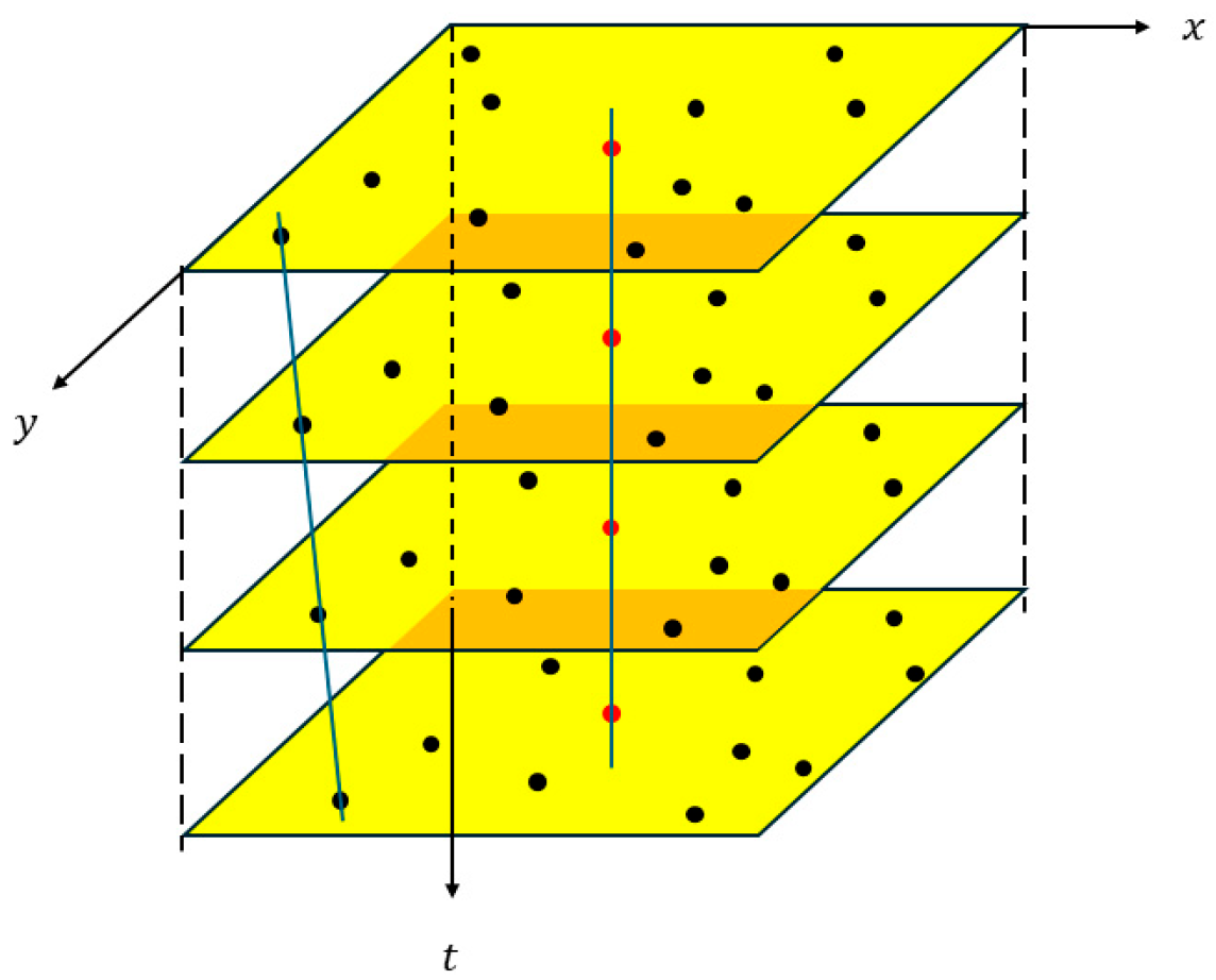
We conducted a further analysis combined with the observation system parameters. The angular resolution of the telescope system used in this study is 8.79 arcseconds per pixel, and the duration of a single observation task is approximately 100 s. According to the calculation based on the sub-satellite point drift rate, the maximum motion amplitude of the GEO target within 100 s is only about 1 arcsecond, which corresponds to a displacement in the image plane much less than 1 pixel, approximately 0.114 pixels. Therefore, within a single observation cycle, the GEO targets can be regarded as a stationary state in the image, and their tiny displacement will not have a substantial impact on the analysis results. Meanwhile, the results of actual imaging also verify our theoretical analysis. The apparent motion is shown in the
Figure 2. The red points represent GEO targets, and the black points represent stars.
Based on the above analysis, the apparent motion velocities of stars and geostationary orbit targets are quantitatively calculated according to the actual working parameters of this paper. This paper monitors the geostationary orbit belt. When the declination of stars in the field of view is 0°, and the angular resolution of the used telescope is 8.79 arcsec/pixel, the apparent motion velocity of stars in the pixel coordinate system is 1.71 pixels per second. Under the condition of a 5–s exposure time, the displacement of stars in each frame is approximately 8 pixels. Considering the influence of the point spread function of starlight, the starlight spot usually occupies about 20–30 pixels. That is, after 3–4 frames of images, the current star can completely move to a new position, and there is no overlap between star images, which makes the minimum value stacking method feasible.
For ground-based optical observatories, Atmospheric Effects should also be concerned. Atmospheric factors (e.g., turbulence, seeing variation) primarily affect the imaging quality of space targets by altering the point spread function of celestial objects and introducing short-term positional jitter. Based on the 150 mm aperture telescope used in this study, we quantitatively analyzed the range of image point shifts induced by atmospheric turbulence by leveraging the Kolmogorov turbulence theory and calculation methods presented in Fried’s work in reference [
21].
Fried’s research establishes that the random angular displacement of celestial image points caused by atmospheric turbulence can be quantified using the Fried parameter r0, where smaller r0 values correspond to stronger turbulence. For conservatism to cover the worst-case conditions for ground-based observations, we selected r0 = 0.1 m—a value far lower than the typical value observed on clear nights. Following the calculation framework in Fried, the root-mean-square (RMS) angular displacement of image points under the above parameters is approximately 1.11 arcsec; the maximum instantaneous displacement is about 3.33 arcsec. Combined with the angular resolution of the telescope used in this study (8.79 arcsec/pixel), this angular displacement translates to a pixel-level shift of only 0.38 pixels. Notably, this 0.38-pixel shift is irregular random jitter that does not accumulate continuously in any specific direction.
In conclusion, atmospheric turbulence only induces minor random image point shifts and does not disrupt the core apparent motion difference between stars and GEO targets. Thus, the proposed Min-Stacking-based GEO target detection method remains valid even under extreme turbulence conditions.
4. Results
In order to evaluate the geostationary orbit target detection method based on the minimum value stacking proposed by us, we conducted experimental verification using measured data. The data used originated from the Small-scale Optoelectronic Innovation and Practice Platform of the Space Engineering University. This platform is equipped with a telescope with a 150-mm aperture and a focal length of 200 mm, which can provide an effective field of view of 10° × 10°. The imaging system employs a domestic CMOS camera, specifically the QHY4040 standard version. The sensor target surface size is 36.9 mm × 36.9 mm, and the image resolution is 4096 × 4096. Its detection capability for high-orbit targets is better than 15 mag (apparent magnitude) @SNR = 5. The working mode is the staring mode, that is, the telescope turns off the tracking system and exposes the designated celestial region. In fact, it rotates synchronously with the Earth.
In order to construct a dataset with diverse scenarios that can reflect the characteristics and advantages of the algorithm proposed in this paper, the following aspects were mainly considered during the data collection process.
Diversity of the selection of celestial regions: The dataset includes 14 celestial regions along the geostationary orbit belt. The number and positions of stars and geostationary orbit targets in each celestial region are different.
Diversity of image quality: The data collection period lasted for one month, and stray light background images taken on different moonlit nights were obtained, covering various image quality conditions such as good, weak, and strong stray light.
Diversity of exposure time: Images with two different exposure times, namely long exposure (5 s) and short exposure (250 ms), were obtained to demonstrate the adaptability of the algorithm in this paper.
Finally, 1680 observation tasks were constructed, with a total of 33,600 images. All the images are stored in FITS format.
The evaluation indicators mainly concerned in this paper are the detection rate, false alarm rate, and detection speed. The constructed variables are shown in
Table 1.
In this paper, the detection speed
is defined as the average time required for the algorithm to process a single-frame image, with the unit of seconds per frame. The calculation methods of the detection rate
and the false alarm rate
are as follows:
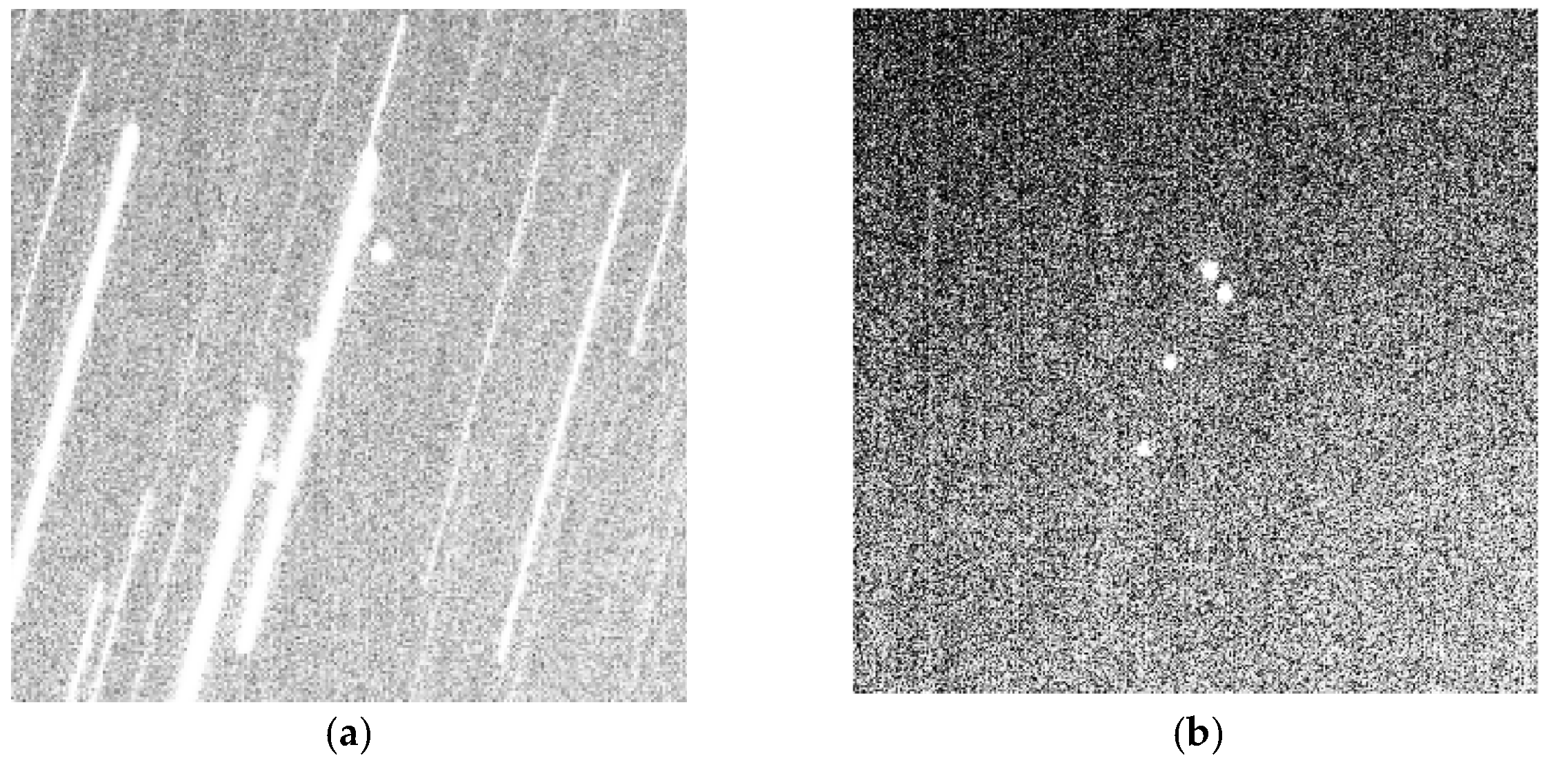
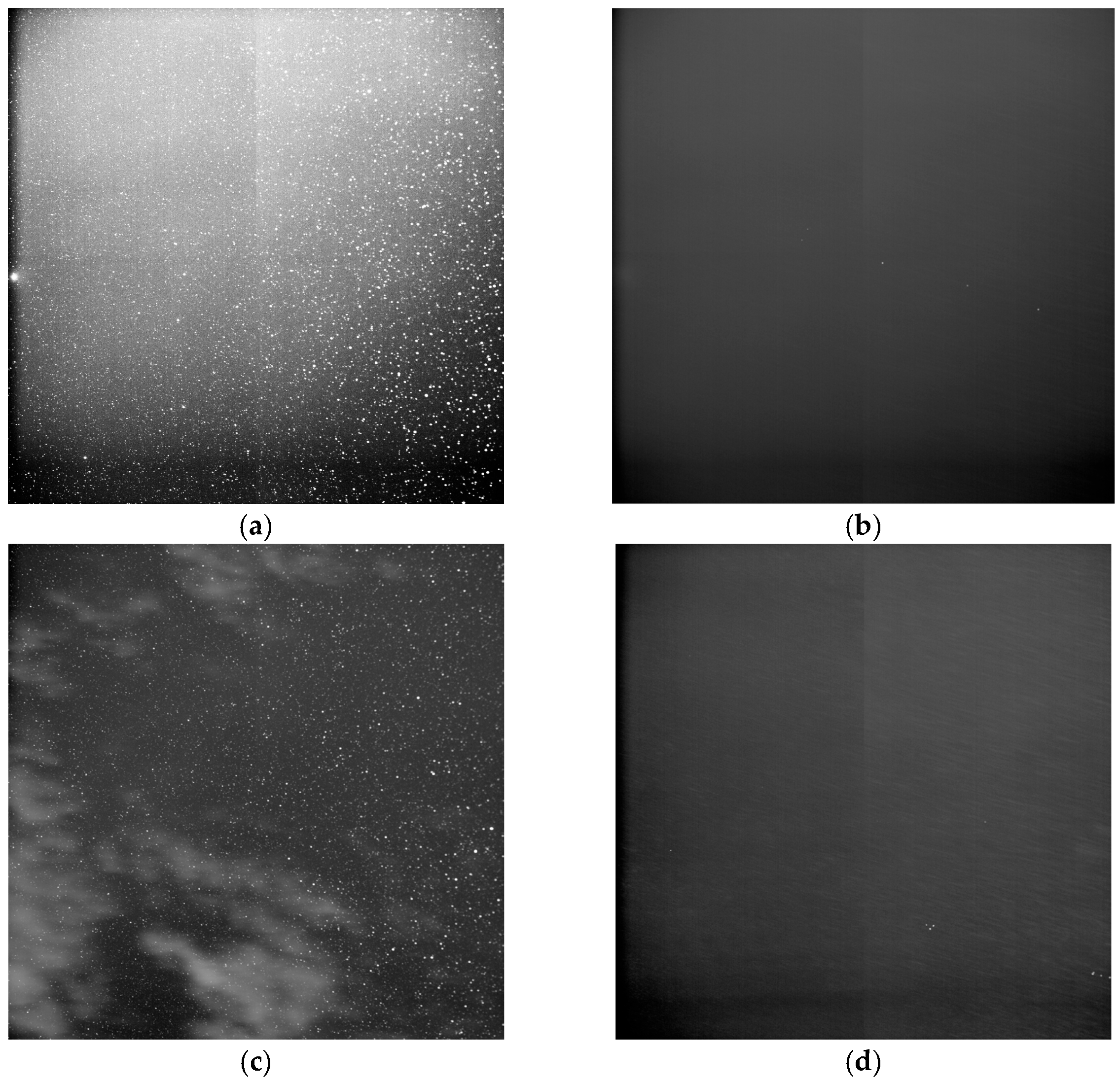
The algorithm proposed in this paper was tested on a computer equipped with an Intel Core i7-12700H processor, 16 GB of RAM, and an NVIDIA GeForce RTX 3070ti LAPTOP graphics card. We present a comparison of images before and after processing with the min-stacking method in
Figure 5. Among these,
Figure 5a shows the original good image with about 7500 stars and 5 GEO targets.
Figure 5b (Min-stacked) shows that stars are suppressed, and all 5 GEO targets are retained.
Figure 5c (original stray light image) has non-uniform background, bright areas from cloud.
Figure 5d (Min-stacked) eliminates the stray light background and can detect GEO targets obscured by cloud. These results confirm that Min-stacking is effective for both good and stray light backgrounds.
To demonstrate the superiority of the method proposed in this paper, we conducted comparative experiments using the mean stacking method and the median stacking method. In terms of the detection rate, our algorithm achieved a geostationary orbit target detection rate as high as 93.15%, and this result is superior to existing similar algorithms. The mean stacking method has a significantly lower detection rate due to the interference of stellar streaks. In contrast, the median stacking method can maintain a relatively good detection rate. However, a high detection rate is sometimes accompanied by a relatively high false alarm rate, that is, non-target objects are mistakenly detected as targets. For our method, the false alarm rate was 3.82%, which reflects the robustness of the algorithm to high-brightness noise points and stray light background images, and it can effectively deal with background noise. Nevertheless, the median stacking method has poor capability in handling non-uniform backgrounds, resulting in a falea alarm rate as high as 10.38%. In addition, the detection speed is also one of the key indicators for measuring the performance of the algorithm. Our algorithm takes an average of 2.31 s to process a single-frame image task, meeting the requirements of real-time applications. This speed benefits from the suppression of stars and the optimization of the calculation process. Moreover, the two comparison methods are inferior to our algorithm in processing speed due to their complex processing procedures. The experimental results of the three methods are shown in the
Table 2,
Table 3 and
Table 4.
In conclusion, the Min-stacking method proposed in this paper exhibits excellent detection performance across different sky regions with varying numbers of stars. Meanwhile, it is applicable to both long-exposure and short-exposure images: it avoids missed detection caused by target occlusion from star trails in long-exposure images, and also overcomes the difficulty in detection due to low target signal-to-noise ratio in short-exposure images. Additionally, the algorithm demonstrates strong robustness against stray light backgrounds, enabling it to effectively control the false alarm rate while maintaining a high detection rate. It also achieves a relatively fast detection speed. Therefore, Min-stacking method is an ideal choice for the application of GEO target detection.
5. Discussion
In this paper, we propose a geostationary orbit target detection method based on the Min-stacking method. This method can quickly and accurately detect geostationary orbit targets in large-field telescope images under the staring mode. By selecting the minimum value for each pixel across multiple frames of images, the method preserves the information of geostationary orbit targets, eliminates the interference of stars, and significantly improves the detection effect of geostationary orbit targets.
The following conclusions can be drawn from this paper: The proposed method reasonably utilizes the difference in apparent motion between stars and geostationary orbit targets, eliminating the need for star registration of sequence images and thus greatly improving the real-time performance of the algorithm. The proposed Min-stacking algorithm can effectively suppress stars in images. Compared with the mean stacking algorithm, it can better handle star occlusion and achieve a higher detection rate. Compared with the median stacking algorithm, it has better robustness to stray light backgrounds and a lower false alarm rate. Benefiting from the high-quality images generated by Min-stacking, this paper adopts a global threshold segmentation algorithm to quickly and accurately detect geostationary orbit targets. Finally, the image positioning of multiple targets is realized through a target positioning algorithm.
The results of actual image processing show that the method proposed in this paper can overcome the difficulties in extracting geostationary orbit targets under complex backgrounds with a large field of view, featuring a high detection rate and a low false alarm rate. Compared with conventional methods, it has the characteristics of high real-time performance and strong detection capability. Nevertheless, the Min-stacking method still has some limitations. Firstly, in the application scenario of large-aperture telescopes, the influence of atmospheric turbulence cannot be ignored. Under such circumstances, the target will have a positional offset in the spatial domain, which may lead to inaccurate target positioning or even detection failure. Secondly, this method is only applicable to strictly stationary geostationary orbit (GEO) targets (with an orbital inclination close to 0° and an orbital period consistent with the Earth’s rotation). For high-orbit satellites such as those in geosynchronous orbit (GSO), the Min-stacking method based on fixed pixels will result in the loss of target information, thereby causing detection failure. Thirdly, when multiple targets in the field of view are relatively close to each other, the gray-scale features of the overlapping area will become blurre. This not only may lead to the misjudgment of multiple targets as a single target, but also increases the centroid positioning error due to the difficulty in determining the ownership of pixels.
To address the identified limitations, future work will focus on optimizing the algorithm from two aspects to enhance its performance. On one hand, the pixel selection rule will be optimized to improve robustness against target displacement and image fluctuations. The current method is only based on a single pixel position. in subsequent iterations, this will be expanded to screening pixel values within a local region centered on the estimated target position. By analyzing the grayscale distribution characteristics of pixels in the window, the core target information can be retained while adapting to slight displacements of non-strictly high-orbit targets and local image fluctuations caused by turbulence in large-aperture telescope imaging, thereby reducing the loss of target information. On the other hand, the positioning algorithm and separation rules for multi-target scenarios will be improved. To tackle the issue of target grayscale overlap, a light spot size constraint will be introduced after min-stacking. Combined with the theoretical light spot size range of different types of high-orbit targets, misjudgments in abnormal overlapping regions will be eliminated. Meanwhile, a single-frame image verification step will be added to compare the grayscale consistency and positional correlation of targets between the min-stacked image and the original single-frame image. This will enable accurate differentiation of the boundaries of overlapping targets, reduce centroid positioning errors, and ensure detection accuracy and positioning precision in multi-target scenarios.
