Article

Constitutive Model Based on Stress Relaxation for Composite Modified Double-Base Propellants and Master Curve of Relaxation Modulus

School of Mechanical Engineering, Key Laboratory of Special Engine Technology, Ministry of Education, Nanjing University of Science and Technology, Nanjing 210094, China
*
Author to whom correspondence should be addressed.
Aerospace 2025, 12(9), 817; https://doi.org/10.3390/aerospace12090817
Submission received: 21 July 2025 / Revised: 3 September 2025 / Accepted: 7 September 2025 / Published: 10 September 2025
(This article belongs to the Section Astronautics & Space Science)

Abstract

This study investigates the constitutive model and relaxation modulus master curve of composite modified double-base (CMDB) propellants through uniaxial constant-rate tensile tests and stress relaxation tests. The experimental observations demonstrate that CMDB propellants exhibit pronounced strain-rate dependence and temperature dependence. Specifically, the yield stress and fracture strength of the propellant increase with increasing strain rate and decrease with increasing temperature. Conversely, the fracture strain increases with increasing temperature. The stress–strain curves of CMDB propellants display marked nonlinearity, attributed to progressive damage accumulation. The relaxation modulus increases significantly with decreasing temperature. Utilizing the time-temperature superposition principle, we constructed a master curve model for the relaxation modulus of CMDB propellants across varying temperatures. Furthermore, based on the observed stress relaxation behavior, a nonlinear constitutive model for CMDB propellants was developed. Theoretical predictions derived from this model show good agreement with experimental data. This model effectively captures the characteristic stress softening and damage evolution in CMDB propellants, thereby providing a theoretical foundation for assessing its mechanical performance and predicting its service life.

1. Introduction

Composite modified double-base (CMDB) propellants are fabricated by incorporating solid particles—such as explosive crystals (e.g., RDX), oxidizer particles (e.g., ammonium perchlorate, AP), and metallic fuels (e.g., Al, Mg)—into a double-base propellant matrix, utilizing an extrusion-casting process. CMDB propellants are widely employed due to their high specific impulse, low signature characteristics, and case-bonded-free grain configuration. With increasing demands on the performance metrics of solid rocket motors, challenges related to the structural integrity of the propellant grain have intensified, positioning this area as a current research focus [1,2]. Conceptually, while double-base propellants can be viewed as polymeric materials, CMDB propellants constitute solid-particle-reinforced composites, exhibiting more complex and anisotropic mechanical behavior. During motor ignition and pressurization, the combustion chamber pressure rapidly rises to approximately 10 MPa within hundreds of milliseconds. This rapid pressurization transient can induce detrimental structural deformations within the propellant grain, insulation layer, and casing, potentially compromising bonded interfaces. Crucially, the resulting mechanical loads on the propellant grain may exceed its permissible design limits, initiating structural damage such as crack formation or grain debonding. These failures increase the instantaneous burning surface area, thereby triggering a rapid overpressure excursion beyond the design limit. This cascade can culminate in combustion instability or catastrophic motor failure [3,4]. Consequently, accurately characterizing the mechanical properties of CMDB propellants under complex loading conditions and establishing robust constitutive relationships describing their mechanical response represent two critical components for conducting high-fidelity structural integrity analysis and assessment of solid propellant grains.
Under sustained and increasing mechanical load, a CMDB propellant develops internal damage mechanisms—primarily debonding at particle-matrix interfaces and matrix tearing—leading to pronounced nonlinearity in its stress–strain response. Over the past two decades, damage mechanics has evolved significantly in scope: from isotropic damage models employing a single scalar variable to anisotropic representations requiring fourth-order tensors [5,6,7,8]. Concurrently, its application domain has expanded to encompass diverse materials, including geological formations [9], asphalt concrete [10], and composite systems [11]. Numerous researchers have adopted continuum damage mechanics (CDM) frameworks to characterize damage evolution in viscoelastic materials. Specifically, viscoelastic CDM formulations based on the work-potential principle [12] have been successfully applied to model damage in asphalt mixtures [13,14,15,16,17,18,19]. Additionally, various micromechanical models [20,21,22,23,24,25,26] have been proposed to simulate the response of viscoelastic materials under complex loading conditions.
Various damage variables have been proposed to characterize the degradation state of materials or structures, predominantly building upon the foundational concept introduced by Kachanov [27]. Lemaitre and Dufailly [28] defined damage as the effective surface density of microcracks and voids on any plane within a representative volume element (RVE), presenting eight distinct damage expressions alongside corresponding measurement techniques and applicable domains. Voyiadjis et al. [29] systematically compared and analyzed damage variables derived from changes in physical parameters—including elastic modulus, bulk modulus, shear modulus, and Poisson’s ratio—and provided the associated damage elasticity tensors for conditions of plane stress, plane strain, and isotropic elasticity. Miller [30] employed non-contact Digital Image Correlation (DIC) to quantify volume dilation in hydroxyl-terminated polybutadiene (HTPB) propellants under uniaxial tension, defining damage as the ratio of volumetric change to initial volume. Yang Jianhong et al. [31] utilized Acoustic Emission (AE) testing to measure the cumulative AE energy release during uniaxial tensile deformation of HTPB propellants, defining damage as the ratio of AE energy at a given deformation state to the total energy at fracture. Similarly, Liu Chengwu et al. [32] employed AE to monitor cumulative energy release during crack initiation in composite solid propellants, defining the damage variable as a linear function of AE energy. Their comparison with a macroscopically defined damage variable (based on modulus degradation) revealed excellent agreement between the resulting damage evolution curves. More recently, Liu Xinguo et al. [33] applied in situ micro-computed tomography (micro-CT) to monitor the uniaxial tensile deformation process of HTPB propellants, utilizing the average grayscale value and average porosity for quantitative characterization of dewetting damage. Yang Qiuqiu et al. [34] combined digital image processing with in situ tensile scanning electron microscopy (SEM), employing fractal dimension analysis for quantitative damage assessment in HTPB, nitrate ester plasticized polyether (NEPE), and glycidyl azide polymer (GAP) propellants. Li Shiqi et al. [35] acquired volumetric porosity data within HTPB propellants under uniaxial tension using a Skyscan1172 micro-CT scanning instrument, establishing a damage variable based on these measurements. Their critical finding revealed that internal damage initiates and evolves during the macroscopic elastic phase without apparent degradation of mechanical properties; significant property degradation manifests only after damage accumulation reaches a critical threshold. Chen [36] developed a nonlinear viscoelastic constitutive model with rate-dependent cumulative damage. The damage model is developed based on the concept of pseudo strain, in which a Prony series representation of viscoelastic material functions is applied. In addition, a rate-dependent damage variable is introduced into the model through considering the rate-dependent characteristics of the cumulative damage process. Zhang [37] used a nonlinear viscoelastic damage constitutive model to describe the tensile-deformation behavior of TB991 weld sealant, and the damage-softening function in the constitutive model was modified. The modified constitutive model can well describe the tensile-deformation behavior of TB991 weld sealant under different temperatures and strain rates. Li Hui [38] proposed a nonlinear viscoelastic constitutive model with novel energy-based damage initiation criterion and an evolution model to describe the coupled effects of confining pressure and strain rate on mechanical responses of CSP. In the developed damage initiation criterion and evolution model, the linear viscoelastic strain energy density was introduced as the damage driving force, and the coupled effects of strain rate, damage history, and confining pressure on damage growth were taken into account.
Furthermore, a CMDB propellant exhibits pronounced temperature dependence in its mechanical properties. Consequently, to accurately characterize the viscoelastic constitutive behavior of composite solid propellants, it is essential to precisely determine the material’s relaxation modulus across varying temperatures. This requires establishing a robust time-temperature superposition (TTS) model to predict the temperature-dependent relaxation modulus. Typically, the relaxation modulus is obtained through static stress relaxation experiments. Owing to the relative simplicity of its data processing, the relaxation modulus has been extensively investigated by researchers globally. Recent advances in data processing methodologies have significantly improved the accuracy in determining relaxation moduli [39,40].
The relaxation modulus obtained at a constant temperature, termed the isothermal relaxation modulus curve, characterizes the material’s mechanical response solely at that specific temperature. In contrast, the temperature-dependent relaxation modulus describes variations in the material’s viscoelastic properties across different temperatures. To accurately model the mechanical behavior of viscoelastic materials under varying thermal conditions, it is essential to construct a precise relaxation modulus master curve. This master curve is typically derived from isothermal relaxation modulus data acquired at multiple discrete temperatures. By applying the time-temperature superposition (TTS) principle to construct the master curve, the evolution of the material’s mechanical properties with temperature can be quantitatively predicted [41,42,43].
Notably, a fundamental challenge in studying the damage within a CMDB propellant lies in distinguishing causality: while damage induces stress softening, observed softening is not exclusively attributable to damage. Consequently, constitutive modeling of propellants must account for additional mechanisms beyond damage. This investigation integrates stress relaxation experiments across varying temperatures, revealing that CMDB propellants retain significant residual stress during relaxation at low-to-intermediate temperatures. Critically, the decay in relaxation stress within a defined strain regime exhibits recoverability. These findings necessitate the explicit incorporation of viscoelastic relaxation effects into the constitutive framework for CMDB propellants. Furthermore, through leveraging the time-temperature superposition (TTS) principle, we have constructed a relaxation modulus master curve characterizing the material’s response across temperatures.

2. Materials and Methods

2.1. Test Materials and Specimens

Composite modified double-base (CMDB) propellant represents an advanced formulation derived from double-base (DB) propellant. Its composition comprises a polymeric matrix of nitrocellulose (NC) and nitroglycerin (NG) plasticizer, reinforced with crystalline explosives (e.g., RDX, HMX), metallic fuels, and additives. This material is synthesized through sequential processing steps: pre-mixing, kneading, dehydration-calendering, and curing/dicing. The CMDB propellant employed in this study has the following composition by mass: 41% NC/NG matrix, 54.6% RDX, and 4.4% minor constituents.
Uniaxial tensile and stress relaxation specimens were machined into a dumbbell type (Figure 1), featuring a 50 mm gauge length. Specimens were aligned coaxially with the loading axis within the grips to preclude stress concentration. Following fabrication, specimens underwent 24 h conditioning in an environmental chamber at 25 ± 2 °C to mitigate machining-induced residual stresses.

2.2. Test Methods

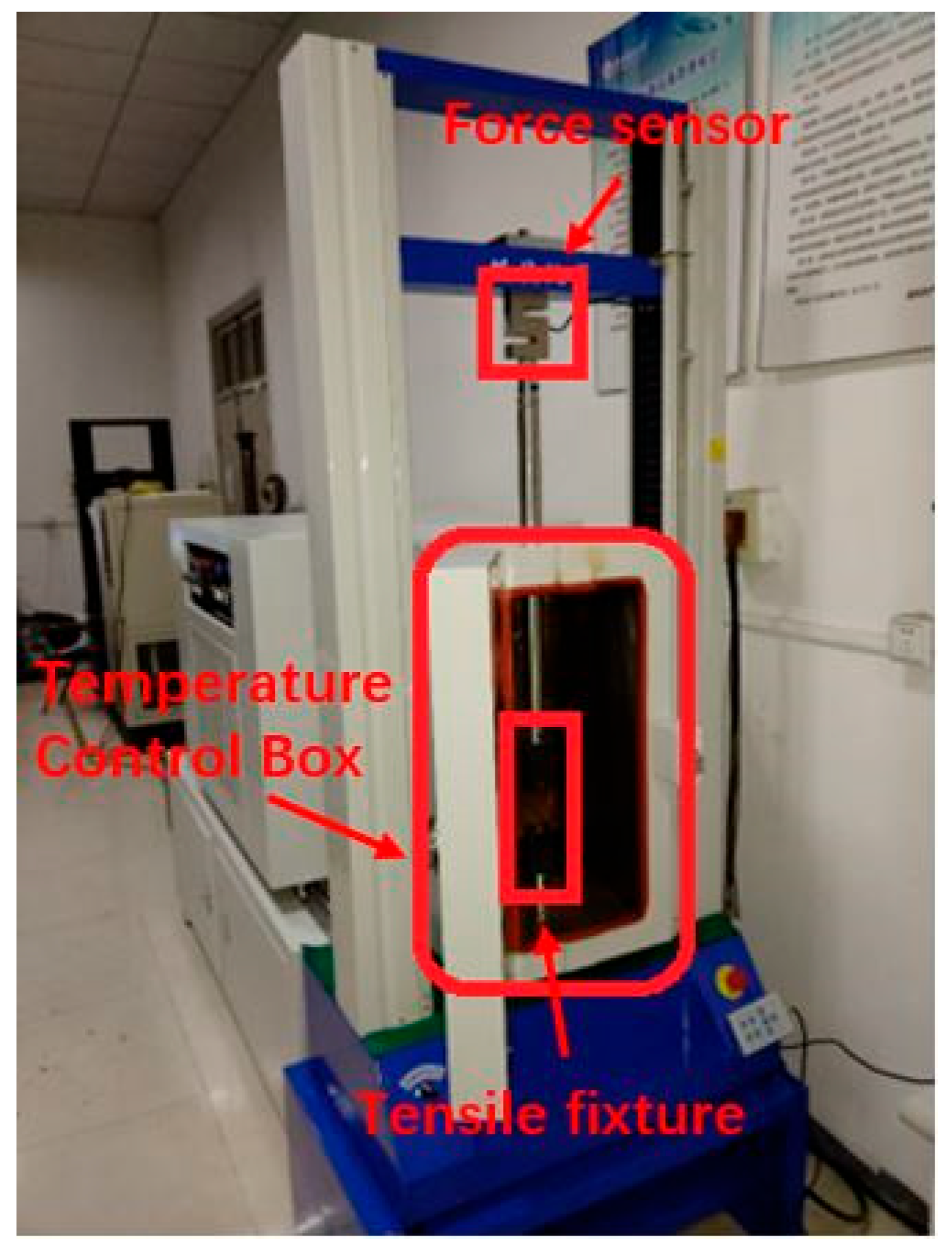
Prior to mechanical testing, specimens were thermally equilibrated in an environmbuxyental chamber to ensure uniform temperature distribution throughout the propellant. Uniaxial tensile properties and stress relaxation behavior were subsequently characterized by using a computer-controlled universal testing machine (QJ211B model, Shanghai Qingji Technology Instrument, Shanghai, China). The experimental setup is detailed in Figure 2.
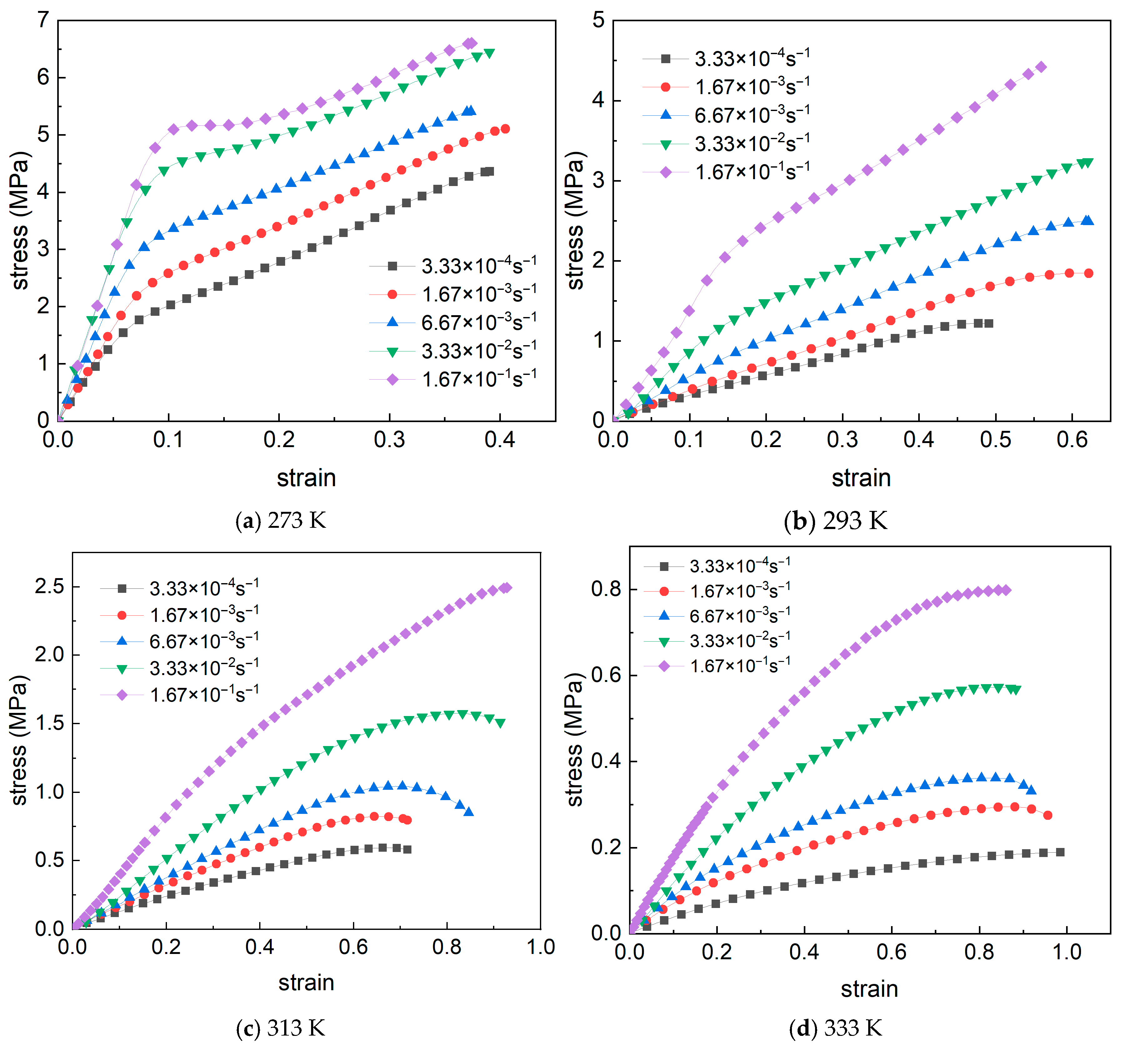
Uniaxial tensile testing was conducted at five constant strain rates—1, 5, 20, 100, and 500 mm·min−1 (3.33 × 10⁻⁴, 1.67 × 10⁻³, 6.67 × 10⁻³, 3.33 × 10⁻², 1.67 × 10⁻¹ s−1)—under four isothermal conditions (273, 293, 313, 333 K). Based on tensile results, a 6% strain level was selected for stress relaxation experiments, corresponding to the linear viscoelastic regime to ensure accurate relaxation modulus determination. Strain was applied at a constant rate of 3.33 × 10⁻² s−1. Upon reaching 6% strain, displacement was held constant while stress decay was continuously monitored. Relaxation tests were performed at six temperatures (223, 248, 273, 293, 313, 333 K). The experiment was repeated multiple times under identical conditions to ensure the ability to obtain three highly repeatable test results. The average of these three curves was then taken as the final stress–strain curve for that operating condition.

3. Results and Discussion

3.1. Uniaxial Tensile Test Results

Uniaxial tensile testing was performed according to the GJB770B-2005 Method 413.1 [44] to obtain characteristic stress–strain curves. Figure 3 presents representative engineering stress–strain responses for the CMDB propellant at four temperatures of 273, 293, 313, and 333 K, and at strain rates of 3.33 × 10⁻⁴, 1.67 × 10⁻³, 6.67 × 10⁻³, 3.33 × 10⁻², and 1.67 × 10⁻¹ s−1. Figure 3 reveals pronounced strain-rate dependence of mechanical properties at constant temperature: flow stress increases with increasing strain rate. Damage evolution mechanisms exhibit fundamental differences across strain-rate regimes: at low strain rates, progressive damage accumulation with stable development; at high strain rates, shortened polymer chain relaxation times prevent matrix deformation, transferring stress directly to rigid fillers (e.g., AP, RDX) and inducing brittle fractures. Consequently, at elevated strain rates, damage progression intensifies through interfacial dewetting—manifested as cavitation at particle-matrix interfaces—observable via scanning electron microscopy (SEM). With a further strain rate increase, this evolves into pronounced matrix tearing and particle fragmentation. Crucially, non-negligible adiabatic heating occurs during deformation, where inelastic work dissipates as heat. This strain-rate-dependent thermal softening (distinct from ambient temperature effects) reduces stress, amplifying temperature rise and consequent mechanical degradation. The interplay between thermal softening and ambient temperature further modulates this response.
CMDB propellants contain inherent micro-defects—including microcracks, microvoids, and particle-matrix dewetting—which evolve under thermo-mechanical loading, progressively degrading mechanical performance. The stress–strain curve exhibits an initial linear elastic regime obeying Hooke’s law. Subsequent modulus reduction induces a transition to nonlinear deformation. At high strain rates and low temperatures, the curve displays a distinct yield point followed by stress reduction. Crucially, failure occurs via coalescence of micro-defects without macroscopic necking—a fundamental distinction from metallic materials.
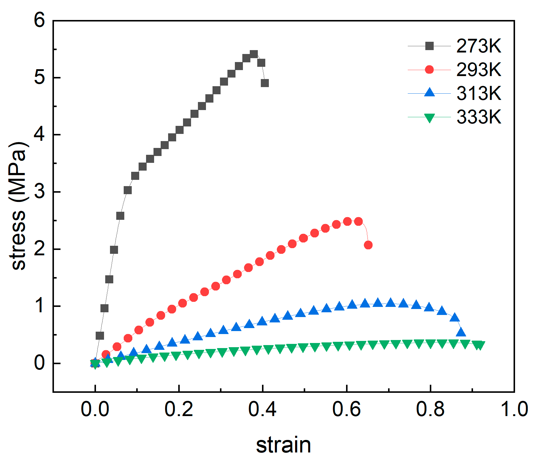
CMDB propellants exhibit significant temperature dependence on mechanical properties. As demonstrated in Figure 4 at a constant strain rate of 6.67 × 10⁻³ s−1, flow stress increases progressively with decreasing temperature. Both Young’s modulus and tensile strength exhibit inverse temperature dependence, while fracture strain increases with rising temperature. Furthermore, the fracture strain increases significantly with rising temperature. Stress–strain curves exhibit consistent morphological trends across temperatures, demonstrating distinct deformation regimes: linear elasticity, yield section, and stress leveling section. At low temperatures, reduced chain segment mobility and diminished free volume amplifies intermolecular friction, significantly elevating the stress response. At elevated temperatures, the material exhibits enhanced viscoelastic behavior. Complementary characterization confirms a glass transition temperature near 273 K, demarcating the boundary between glassy and rubbery states. As the temperature rises, the propellant material transitions from the glassy state into the glass transition region (268 K). Upon further temperature increase, the material shifts to the rubbery state (313 K), exhibiting significant modulus variation with temperature and demonstrating a certain degree of deformation capability. While full polymer chain motion remains restricted, enhanced thermal energy promotes localized segmental mobility through short-range diffusion. As shown in Figure 4, the temperature-dependent fracture strain directly originates from these viscoelastic characteristics, demonstrating time-temperature superposition behavior.
Pronounced yield phenomena were consistently observed across the tested temperature range (273, 293, 313, 333 K). Analysis indicates two primary mechanisms that govern yield zone formation in propellants: on the one hand, intrinsic mechanisms where plastic deformation of the binder matrix coupled with high-volume fractions of rigid particulates (e.g., ammonium perchlorate, AP) induces macroscopic dewetting at particle-matrix interfaces. On the other hand, extrinsic mechanisms whereby thermomechanical loading accelerates micro-crack propagation, generates cavitation and consequent rapid volumetric expansion that manifests as macroscopic yielding. At a constant strain rate, decreasing temperature elevates the critical dewetting stress, thereby suppressing interfacial failure initiation. This mechanistic transition shifts damage evolution toward binder tearing and particle fracture under cryogenic conditions.

3.2. Relaxation Test Results

For viscoelastic materials, the strain ε ( t ) = ε 0 of the material during stress relaxation is at a strain rate of ε ˙ ( t ) = 0 . Therefore, the stress response of the material is obtained as σ ( t ) = E ( t ) ε 0 according to the linear viscoelastic intrinsic model, and the change in the relaxation modulus E ( t ) of the material with respect to time can be expressed as E ( t ) = σ ( t ) / ε 0 .
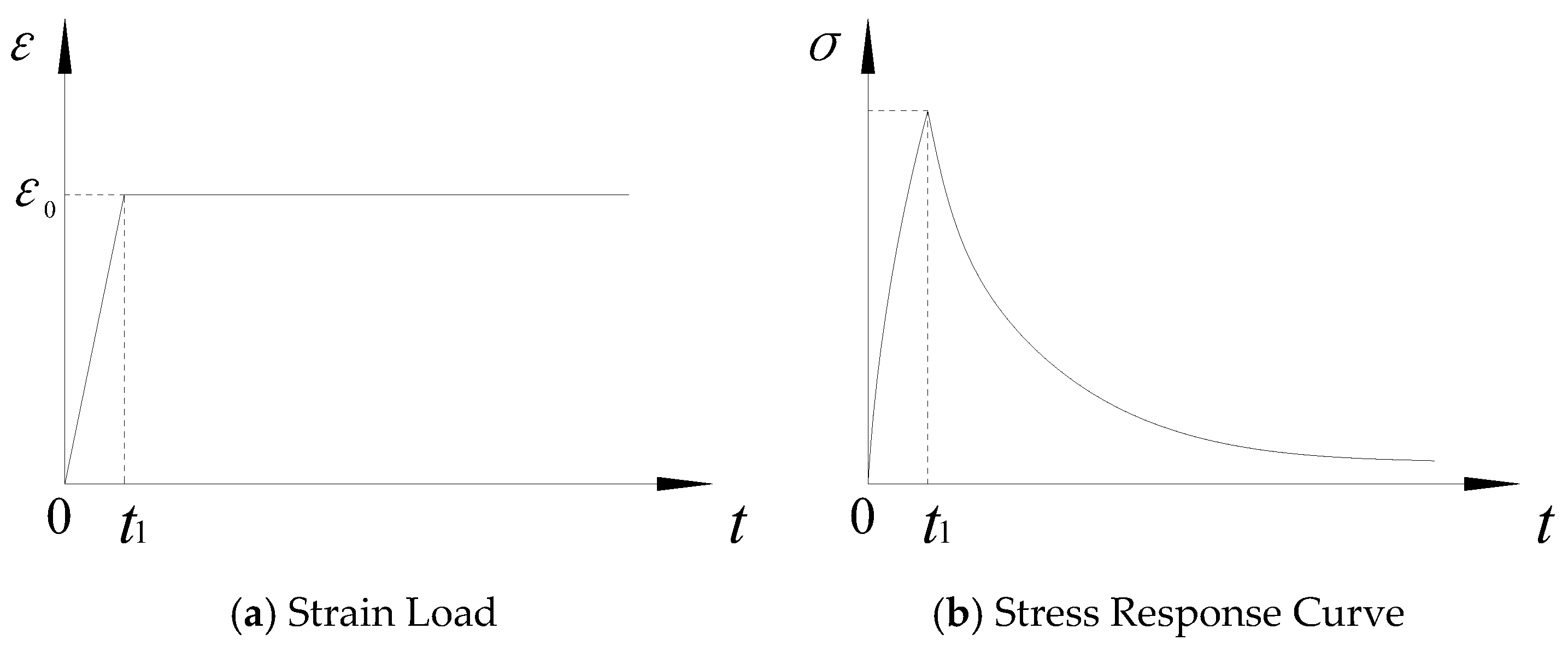
In the relaxation experiment, since it is difficult to obtain the step load ε 0 required by the theory in the experimental machine, the actual relaxation experiment is to stretch or compress the specimen at an equal strain rate ε ˙ 0 for a period of time t 1 to reach a constant strain value ε 0 = ε ˙ 0 t 1 and keep the strain value ε 0 for a certain period of time, and then record the stress response of the material in real time, the actual strain loading process is shown in Figure 5.
In general data processing, the process of strain rise is often ignored, and the moment t 1 at which the strain reaches ε 0 is taken as the initial moment of the relaxation experiment, then the relaxation modulus can be expressed as:
E ( t ) = F ( t + t 1 ) ( 1 + ε 0 ) A 0 ε 0
where E ( t ) is the relaxation modulus, F ( t ) is the force measured by the force transducer, A 0 is the initial cross-sectional area of the specimen, and ε 0 is the relaxation strain level.
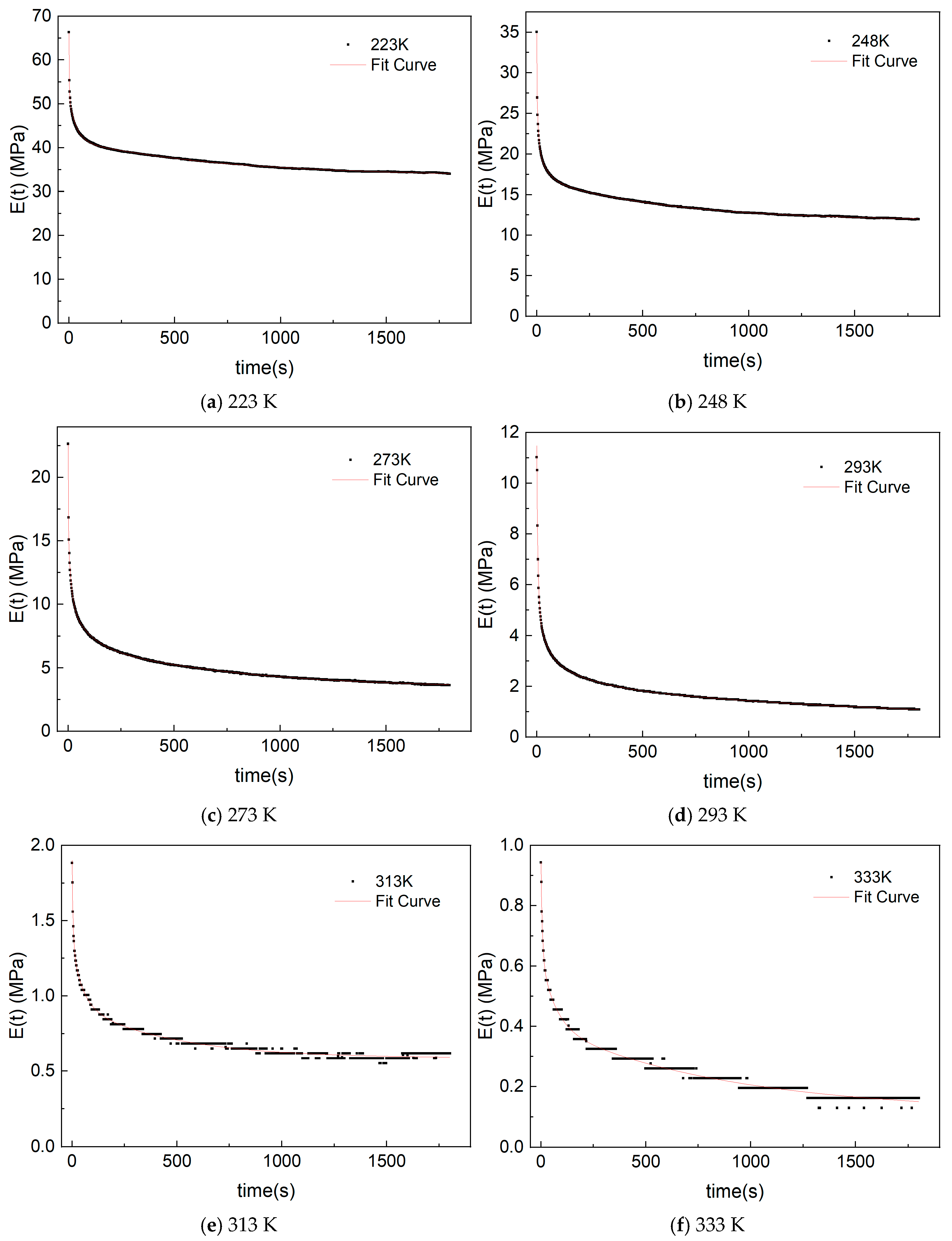
The results of the relaxation experiments for the CMDB propellant at 223 K, 248 K, 273 K, 293 K, 313 K, and 333 K are shown in Figure 6. From Figure 6, it can be observed that the relaxation modulus decays significantly with time, and the relaxation modulus decreases sharply at first, which is due to the fact that the dominant response mechanisms of the CMDB propellant during the initial 10 s of relaxation are primarily chain disentanglement in plasticized nitrocellulose and interfacial slip at AP/RDX particulate boundaries, and this process exhibits recoverability. In the subsequent 100 s interval, it is a synergistic combination of continued molecular chain disentanglement and microdomain rearrangement within nitroglycerine plasticizer phases, so that the relaxation modulus undergoes gradual reduction and asymptotically approaches a stabilized value.
As further evidenced in Figure 6, the relaxation modulus exhibits significant temperature dependence, with the relaxation modulus of the CMDB propellant increasing substantially as temperature decreases. The modulus at 223 K is nearly 100-fold greater than at 333 K, necessitating strict consideration of thermal effects in characterizing propellant relaxation behavior. Critically, the modulus asymptotically approaches a non-zero equilibrium value rather than decaying to zero, where lower temperatures yield higher residual moduli. Consequently, constitutive modeling of CMDB propellants must explicitly incorporate stress relaxation effects.

3.3. Master Curve of Relaxation Modulus

Identical mechanical relaxation phenomena in viscoelastic materials can be observed either at elevated temperatures under brief loading durations or at reduced temperatures under extended loading times. This characteristic response, termed thermorheological simplicity, arises from temperature-dependent molecular mobility: at low-temperature regimes, restricted thermal motion extends relaxation times, and at high-temperature regimes, enhanced molecular mobility shortens relaxation times. Thus, modifications in temperature scales equivalently influence mechanical properties as modifications in time scales—the fundamental basis of the time-temperature superposition principle [45].
Researchers have employed diverse time-temperature superposition models to characterize the relationship between temperature and the temperature shift factor log a T for various viscoelastic materials [46,47,48,49]. Among these, the Williams–Landel–Ferry (WLF) equation demonstrates the broadest applicability, expressed as (2) [46]:
log a T = C 1 T T ref C 2 + T T ref
where C 1 and C 2 are material constants, T ref denotes the reference temperature.
The relaxation modulus expression is:
E ( t ) = E + i = 1 8 E i exp ( t τ i )
where E represents the steady-state relaxation modulus, E i denotes the i order relaxation modulus, and τ i indicates the i order characteristic time.
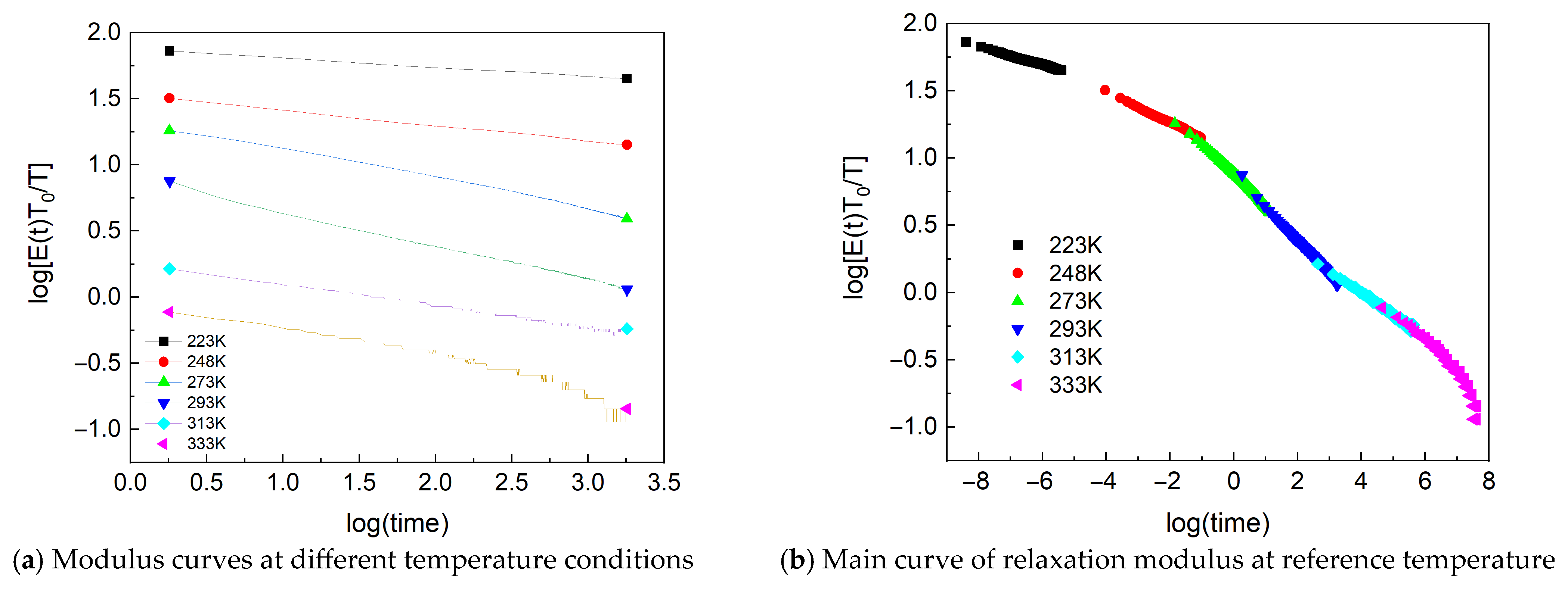
Figure 7a presents the logarithmic relaxation modulus curves at distinct temperature levels. As evidenced in Figure 6 and Figure 7, the magnitude of relaxation modulus exhibits substantial temperature dependence, with its value increasing significantly as temperature decreases. Despite temperature variations, stress relaxation phenomena demonstrate consistent characteristics: pronounced stress decay occurs during the initial relaxation phase, progressively diminishing over time.
Based on the time-temperature equivalence principle, the mechanical properties of the material are first obtained at different temperatures to derive a set of relaxation modulus curves at various temperatures, plotted on a logarithmic coordinate system, as shown in Figure 7a. Subsequently, the modulus curves from different temperatures are temperature-corrected within the same logarithmic coordinate system. A specific temperature is selected as the reference temperature. The modulus curves corresponding to different temperatures are then shifted to overlap with the modulus curve at the reference temperature, yielding the relaxation modulus master curve, as shown in Figure 7b. The shift values required for each modulus curve are recorded, representing the logarithmic values of the time-temperature equivalence factors log a T .
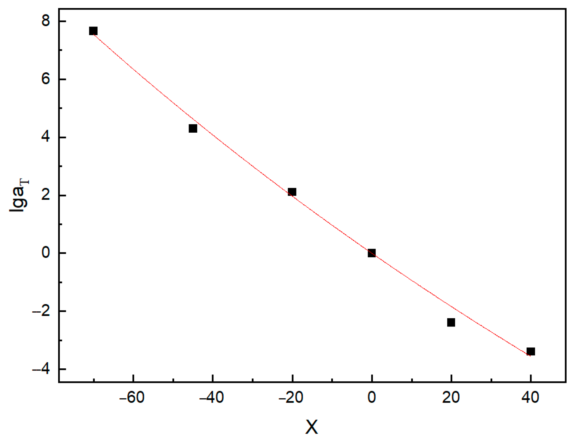
Employing the time-temperature shift factor methodology detailed previously with 293 K as the reference temperature, shift factors for discrete temperatures were determined and fitted to establish the time-temperature superposition model. Figure 8 presents the empirical correlation, where the abscissa denotes T T ref values. The model parameters are C 1 = 55.99193 and C 2 = 589.65679.
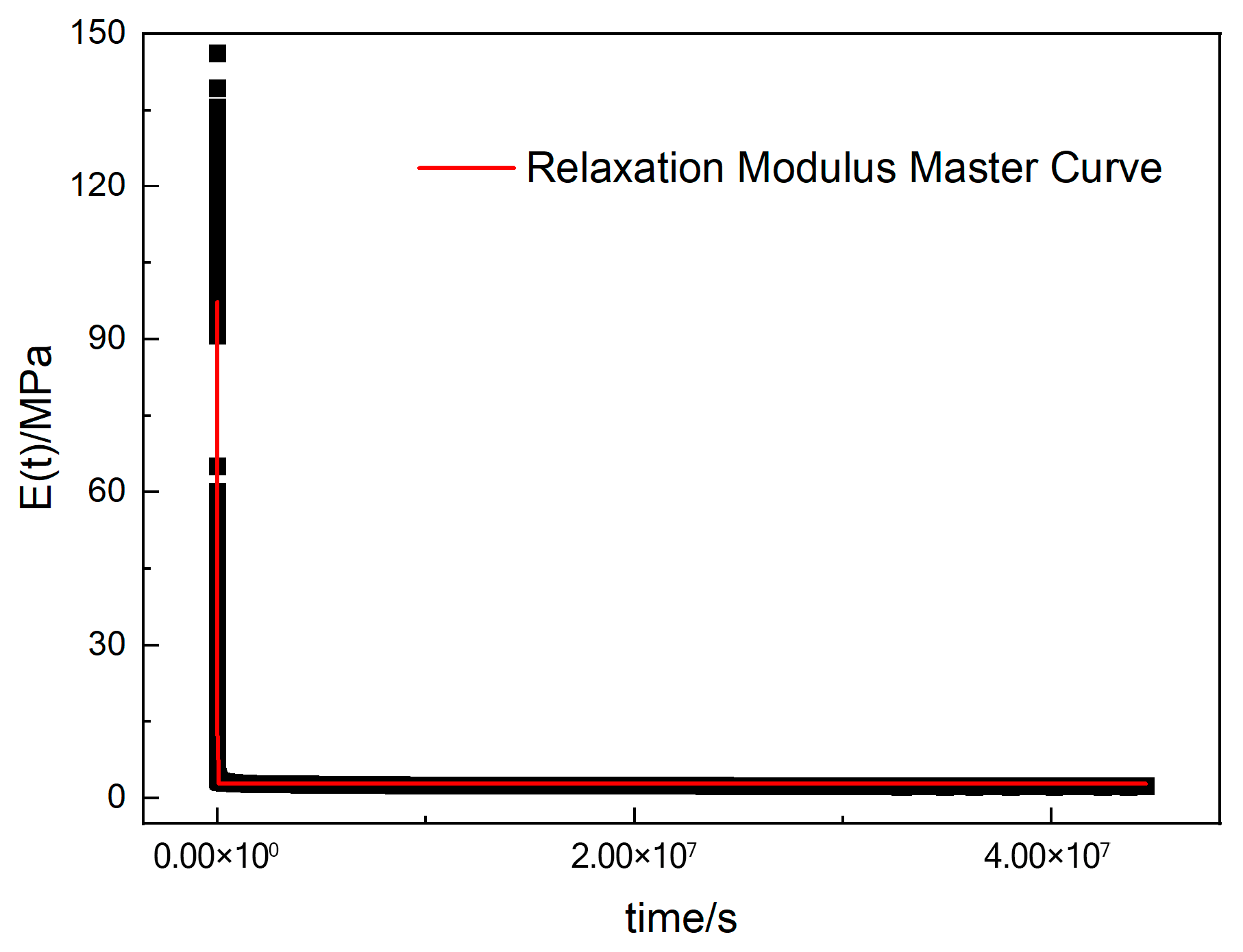
Leveraging the time-temperature shift factors obtained under discrete thermal conditions, relaxation curves across temperature levels were horizontally shifted to superimpose with the reference temperature curve, thereby constructing the relaxation modulus master curve. The data were fitted to an eighth-order Prony series representation, with the fitting results presented in Figure 9. The eighth-order Prony series relaxation modulus master curve model is expressed as:
E ( t ) = 2.8059 + 45.52073   exp ( t 0.001 ) + 15.77105   exp ( t 0.01 )                   + 11.47176   exp ( t 0.1 ) + 9.4272   exp ( t 1 ) + 6.98546   exp ( t 10 )                   + 2.15831   exp ( t 100 ) + 1.87528   exp ( t 1000 ) + 1.39286   exp ( t 10000 )

3.4. Constitutive Model Based on Stress Relaxation for Composite Modified Double-Base Propellants

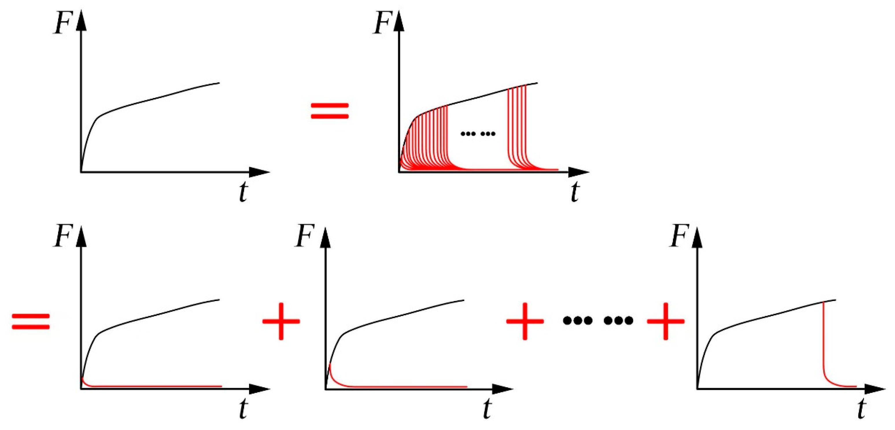
Analysis of stress relaxation test data revealed that the residual relaxation modulus of the CMDB propellant approached one-third of its initial value, indicating the significant influence of stress relaxation on the propellant’s mechanical properties. This observation motivated the development of a progressive stress relaxation superposition model. This model decomposes the uniaxial tensile response into two components: (i) the superposition of multiple sequential stress relaxation decay processes and (ii) strain-induced material damage. A schematic representation of the sequential stress relaxation superposition concept is provided in Figure 10.
To characterize the stress relaxation softening effect in CMDB propellants under tensile loading, a simplified Maxwell viscoelastic model was introduced. By leveraging the evolutionary trend of the relaxation curve, the relaxation modulus was correlated with material stiffness. This approach enables enhanced characterization of the stress relaxation superposition process, with the relaxation modulus expressed as:
E t = E e t / τ
During constant-rate uniaxial tensile testing, the invariant strain rate implies that the progression of time corresponds directly to an increase in strain. This relationship can be expressed as:
E ε   ·   L V = E e ε · L / V τ
The above expression represents the modulus attenuation equation for the stress relaxation input component. Assuming a stress softening magnitude of σ r induced by relaxation at specimen failure, the corresponding stress softening σ 1 at strain ε can be derived as:
σ 1 = σ r 1 e R 1 ε
where σ r and R 1 are material parameters, with R 1 = L / V τ , σ r denoting the cumulative stress softening at specimen failure, induced by relaxation and relating to the strain range Δ ε . Damage corresponding to this component exhibits partial recoverability due to the viscoelastic nature of the propellant.
To characterize damage-induced stress reduction, a damage model is introduced. Denoting the cumulative stress reduction at specimen failure by damage as σ S , the corresponding stress reduction σ 2 at strain ε can be expressed as:
σ 2 = σ S 1 1 ε R 2
where a and b denote material parameters, Table 1 presents the constitutive model parameters for the CMDB propellant at 273 K. Thus, the damage-integrated constitutive model for CMDB propellants is derived as:
σ = σ r 1 e R 1 ε + σ S 1 1 ε R 2
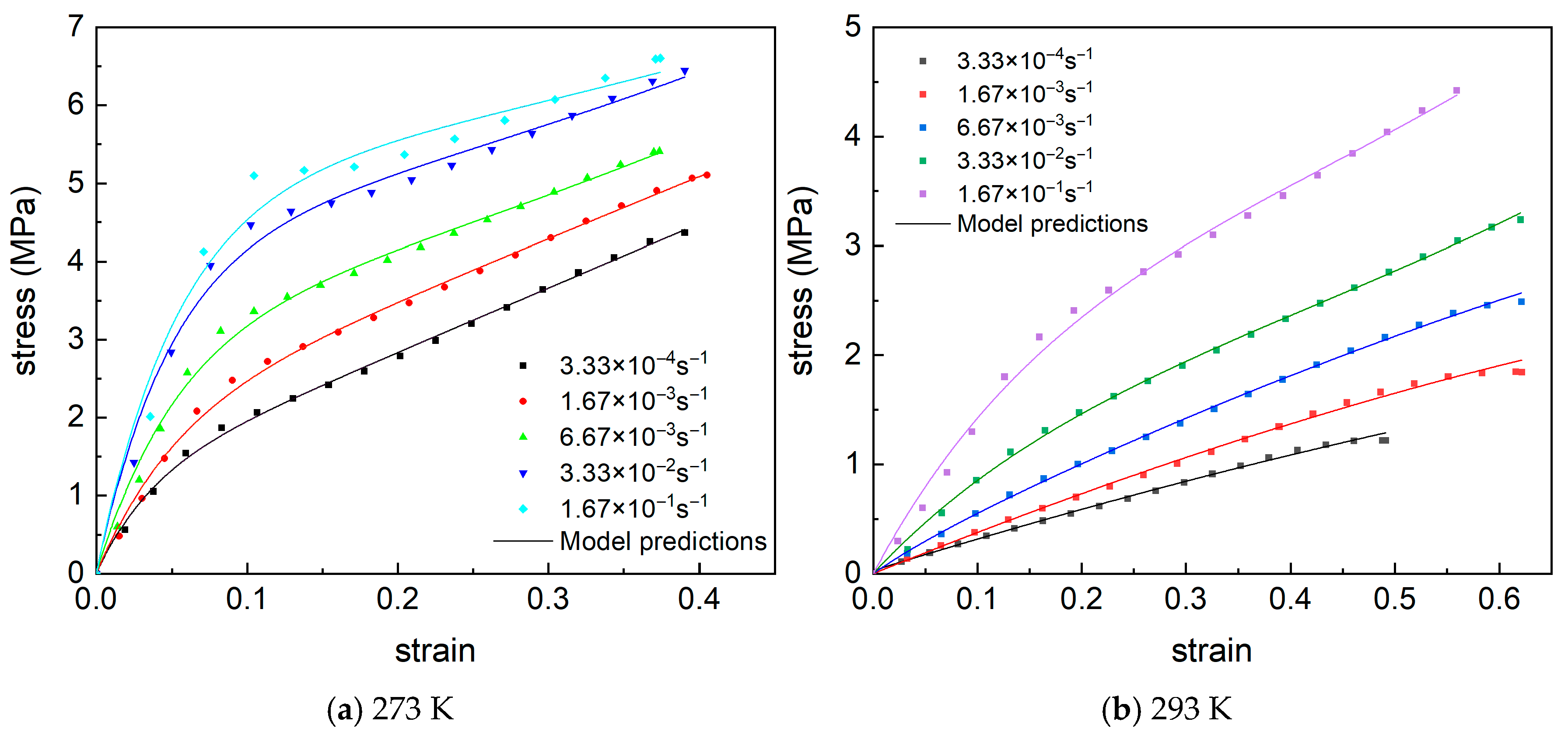
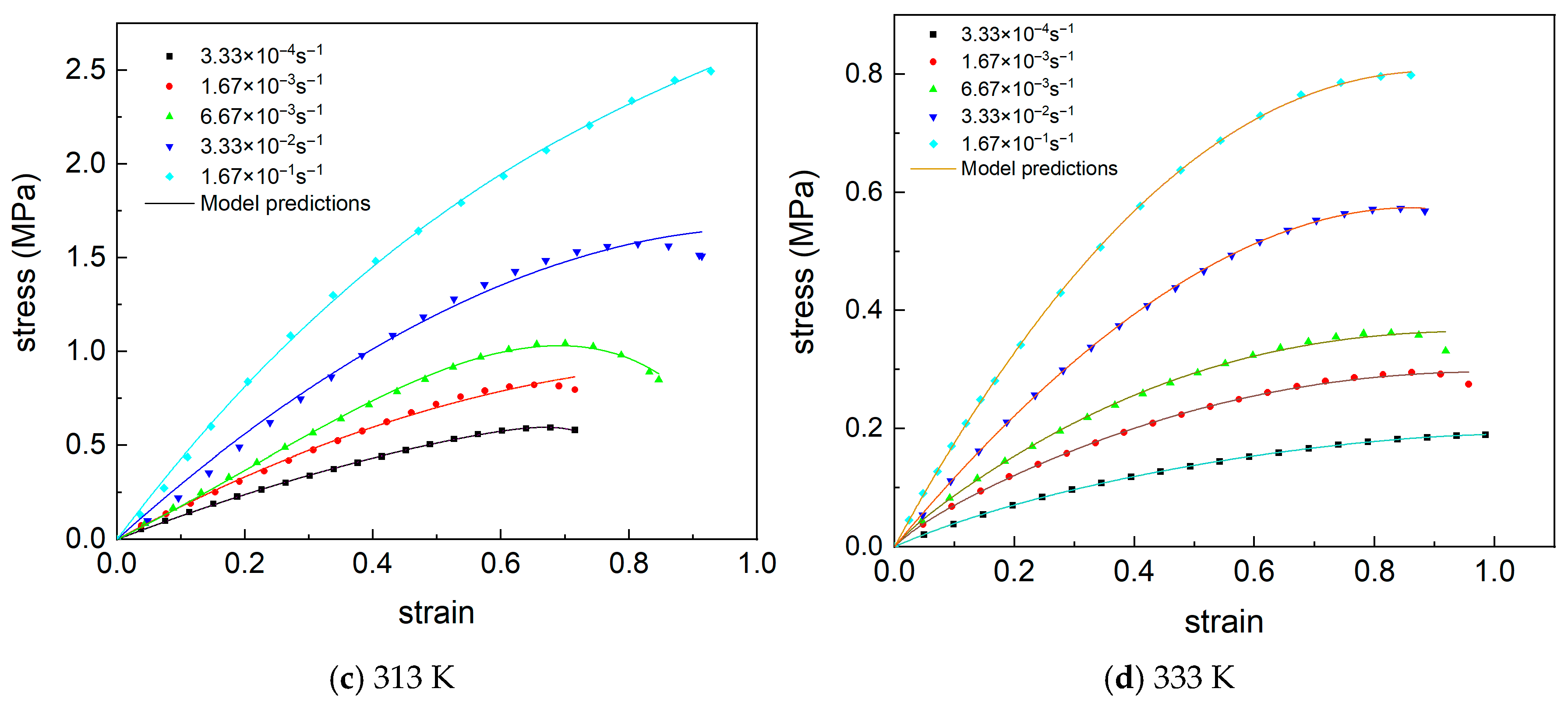
Figure 11 compares model predictions with experimental results across varying temperatures and strain rates. The constitutive model exhibits excellent agreement with experimental data, demonstrating its capability to accurately capture the stress–strain response of the CMDB propellant under the investigated thermomechanical conditions.

4. Conclusions

This study investigates the strain-rate and temperature dependence of CMDB propellants through uniaxial constant-rate tensile tests, while characterizing its stress relaxation behavior at varying temperatures via relaxation experiments. Applying the time-temperature superposition principle, we established a Prony series-based master curve model for the relaxation modulus. Subsequently, a nonlinear constitutive model incorporating stress relaxation effects was developed for the CMDB propellant.
The CMDB propellant exhibited pronounced strain-rate sensitivity and thermo-mechanical coupling. Both fracture strength and yield stress increased with increasing strain rate and decreased with elevating temperature. Conversely, elongation at break increases with temperature. The relaxation modulus demonstrates a steep enhancement with decreasing temperature.
The stress reduction under tensile loading arises not only from damage accumulation but also from inherent viscoelasticity. These distinct mechanisms must be differentiated in constitutive modeling. We therefore rigorously developed an enhanced nonlinear constitutive framework that explicitly accounts for stress relaxation phenomena in CMDB propellants.

Author Contributions

Conceptualization, Y.L.; methodology, Y.L. and J.X.; software, Y.L.; validation, J.X., C.Z. and X.C.; formal analysis, Y.L.; investigation, X.Y.; resources, X.Y.; data curation, J.X.; writing—original draft preparation, Y.L.; writing—review and editing, J.X.; visualization, C.Z.; supervision, X.C.; project administration, X.Y.; funding acquisition, J.X. All authors have read and agreed to the published version of the manuscript.

Funding

This research received no external funding.

Data Availability Statement

The datasets used during the current study are available from the corresponding author on reasonable request.

Conflicts of Interest

The authors declare no conflicts of interest.

References

  1. Gong, J.L.; Li, P.; Zhang, Z.Z.; Gong, W.J.; Li, W.F. Research progress on structural integrity of solid rocket motor grains. Sci. Technol. Eng. 2021, 21, 434–441. [Google Scholar]
  2. Wei, X.L.; Zhou, J.H.; Li, H.Y.; Shu, H.M. Advances in structural integrity analysis of solid propellant grains. J. Ordn. Equip. Eng. 2022, 43, 19–26. [Google Scholar]
  3. Godai, T. Flame propagation into the crack of solid-propellant grain. AIAA J. 1970, 8, 1322–1327. [Google Scholar] [CrossRef]
  4. Kumar, M.; Kovacic, S.M.; Kuo, K.K. Flame propagation and combustion processes in solid propellant cracks. AIAA J. 1981, 19, 610–618. [Google Scholar] [CrossRef]
  5. Lemaitre, J.; Desmorat, R.; Sauzay, M. Anisotropic damage law of evolution. Eur. J. Mech.-A Solids 2000, 19, 187–208. [Google Scholar] [CrossRef]
  6. Voyiadjis, G.Z.; Park, T. Anisotropic damage effect tensors for the symmetrization of the effective stress tensor. J. Appl. Mech. 1997, 64, 106–110. [Google Scholar] [CrossRef]
  7. Voyiadjis, G.Z.; Abu Al-Rub, R.K. A finite strain plastic-damage model for high velocity impacts using combined viscosity and gradient localization limiters: Part II-numerical aspects and simulations. Int. J. Damage Mech. 2006, 15, 335–373. [Google Scholar] [CrossRef]
  8. Manu, H.; Shantanu, M. Evolving structural tensor approach to model the damage induced anisotropy in viscoelastic solids. Int. J. Solids Struct. 2022, 248, 111655. [Google Scholar] [CrossRef]
  9. Zhao, G.M.; Xie, L.X.; Meng, X.R. A damage-based constitutive model for rock under impacting load. Int. J. Min. Sci. Technol. 2014, 24, 505–511. [Google Scholar] [CrossRef]
  10. Park, S.W.; Richard, K.Y.; Schapery, R.A. A viscoelastic continuum damage model and its application to uniaxial behavior of asphalt concrete. Mech. Mater. 1996, 24, 241–255. [Google Scholar] [CrossRef]
  11. Voyiadjis, G.Z.; Taqieddin, Z.N.; Kattan, P.I. Micromechanical approach to damage mechanics of composite materials with fabric tensors. Compos. Part B Eng. 2007, 38, 862–877. [Google Scholar] [CrossRef]
  12. Schapery, R.A. A theory of mechanical behavior of elastic media with growing damage and other changes in structure. J. Mech. Phys. Solids 1990, 38, 215–253. [Google Scholar] [CrossRef]
  13. Gibson, N.; Schwartz, C.; Schapery, R.; Witczak, M. Viscoelastic, viscoplastic, and damage modeling of asphalt concrete in unconfined compression. Transp. Res. Rec. J. Transp. Res. Board 2003, 1860, 3–15. [Google Scholar] [CrossRef]
  14. Kim, Y.R.; Daniel, J.S.; Wen, H. Fatigue Performance Evaluation of WesTrack Asphalt Mixtures Using Viscoelastic Continuum Damage Approach; North Carolina Department of Transportation: Raleigh, NC, USA, 2002. [Google Scholar]
  15. Lee, H.; Daniel, J.; Kim, Y. Continuum damage mechanics-based fatigue model of asphalt concrete. J. Mater. Civ. Eng. 2000, 12, 105–112. [Google Scholar] [CrossRef]
  16. Lee, H.; Kim, Y. Viscoelastic continuum damage model of asphalt concrete with healing. J. Eng. Mech. 1998, 124, 1224–1232. [Google Scholar] [CrossRef]
  17. Sullivan, R.W. Development of a viscoelastic continuum damage model for cyclic loading. Mech. Time-Depend. Mater. 2008, 12, 329–342. [Google Scholar] [CrossRef]
  18. Underwood, B.; Baek, C.; Kim, Y. Simplified viscoelastic continuum damage model as platform for asphalt concrete fatigue analysis. Transp. Res. Rec. J. Transp. Res. Board 2012, 2296, 36–45. [Google Scholar] [CrossRef]
  19. Underwood, B.S.; Kim, Y.R.; Guddati, M.N. Characterization and Performance Prediction of ALF mixtures using a viscoelastoplastic continuum damage model (with discussion). In Proceedings of the Association of Asphalt Paving Technologists-Proceedings of the Technical Sessions 2006 Annual Meeting, Savannah, GA, USA, 27–29 March 2006. [Google Scholar]
  20. Dai, Q.; Sadd, M.H.; You, Z. A micromechanical finite element model for linear and damage-coupled viscoelastic behaviour of asphalt mixture. Int. J. Numer. Anal. Methods Geomech. 2006, 30, 1135–1158. [Google Scholar] [CrossRef]
  21. Guddati, M.; Feng, Z.; Kim, Y. Toward a micromechanics-based procedure to characterize fatigue performance of asphalt concrete. Transp. Res. Rec. J. Transp. Res. Board 2002, 1789, 121–128. [Google Scholar] [CrossRef]
  22. Kim, Y.; Allen, D.; Little, D. Damage-induced modeling of asphalt mixtures through computational micromechanics and cohesive zone fracture. J. Mater. Civ. Eng. 2005, 17, 477–484. [Google Scholar] [CrossRef]
  23. Lytton, R.L.; Chen, C.W.; Little, D.N. Microdamage Healing in Asphalt and Asphalt Concrete, Volume III: A Micromechanics Fracture and Healing Model for Asphalt Concrete; Turner-Fairbank Highway Research Center: McLean, VA, USA, 2001. [Google Scholar]
  24. Onifade, I.; Jelagin, D.; Guarin, A.; Birgisson, B.; Kringos, N. Effect of micro-scale morphological parameters on meso-scale response of Asphalt Concrete. In Asphalt Pavements; CRC Press: Boca Raton, FL, USA, 2014; pp. 1775–1784. [Google Scholar]
  25. Sadd, M.; Dai, Q.; Parameswaran, V.; Shukla, A. Simulation of asphalt materials using finite element micromechanical model with damage mechanics. Transp. Res. Rec. J. Transp. Res. Board 2003, 1832, 86–95. [Google Scholar] [CrossRef]
  26. Tashman, L.; Masad, E.; Zbib, H.; Little, D.; Kaloush, K. Microstructural viscoplastic continuum model for permanent deformation in asphalt pavements. J. Eng. Mech. 2005, 131, 48–57. [Google Scholar] [CrossRef]
  27. Kachanov, L.M. Rupture time under creep conditions. Izviestia Akad. Nauk. SSSR Otd. Tekh. Nauk. 1958, 8, 26–31. [Google Scholar] [CrossRef]
  28. Lemaitre, J.; Dufailiy, J. Damage measurements. Eng. Fract. Mech. 1987, 28, 643–661. [Google Scholar] [CrossRef]
  29. Voyiadjis, G.Z.; Kattan, P.I. A comparative study of damage variables in continuum damage mechanics. Int. J. Damage Mech. 2008, 18, 315–340. [Google Scholar] [CrossRef]
  30. Miller, T.C. Damage and dilatometry for solid propellants with digital image correlation. Propellants Explos. Pyrotech. 2018, 44, 234–245. [Google Scholar] [CrossRef]
  31. Yang, J.H.; Wang, F.W.; Qin, S.Y. Experimental and theoretical study on acoustic emission characteristics and damage modeling of HTPB composite solid propellants. J. Solid Rocket Technol. 2000, 23, 37–40. [Google Scholar]
  32. Liu, C.W.; Yang, J.H.; Zhang, H. Acoustic emission monitoring of damage evolution in composite solid propellants. Aerosp. Shanghai 2011, 28, 69–72. [Google Scholar]
  33. Liu, X.G.; Liu, P.J.; Qiang, H.F.; Zhang, Y. Quantitative characterization of dewetting in HTPB propellant via micro-CT. J. Propul. Technol. 2019, 40, 1162–1180. [Google Scholar]
  34. Yang, Q.Q.; Xu, S.L.; Cai, R.L.; Zhang, J.; Qiang, F.Z.; Huang, Z.P. Mesoscopic damage behavior of composite propellants through digital image processing. J. Solid Rocket Technol. 2022, 45, 83–91. [Google Scholar]
  35. Li, S.Q.; Qiang, H.F.; Wang, G.; Wang, X.R.; Liu, X.G.; Wang, J.X. Experimental investigation on meso-damage evolution of HTPB propellant under uniaxial tension. J. Propul. Technol. 2022, 43, 411–417. [Google Scholar]
  36. Chen, S.; Wang, C.; Zhang, K.; Lu, X.; Li, Q. A nonlinear viscoelastic constitutive model for solid propellant with rate-dependent cumulative damage. Materials 2022, 15, 5834. [Google Scholar] [CrossRef] [PubMed]
  37. Zhang, J.; Zhang, X.; Wang, Z.Z.; Li, H.Y. An experimental and modeling investigation on the effects of temperature and strain rate on the tensile-deformation behavior of TB991 weld sealant. Mech. Time-Depend. Mater. 2023, 27, 119–138. [Google Scholar] [CrossRef]
  38. Li, H.; Xu, J.S.; Chen, X.; Zhang, J.F.; Li, J. A nonlinear viscoelastic constitutive model with damage and experimental validation for composite solid propellant. Sci. Rep. 2023, 13, 2049. [Google Scholar] [CrossRef] [PubMed]
  39. Xu, J.; Ju, Y.; Zheng, J.; Han, B. Acquiring the Relaxation Modulus of Composite Solid Propellant. Chin. J. Explos. Propellant 2011, 34, 58–62. [Google Scholar]
  40. Honglei, M.; Yutao, J.; Changsheng, Z. Determination Way of Relaxation Modulus of Modified DB Propellant. Eng. Mech. 2012, 29, 359–362. [Google Scholar]
  41. Quanxing, H.; Yudong, J.; Jian, L. Fitting of Relaxation Modulus Master Curve for Solid Propellant and W.L.F Equation Parameters. J. Solid Rocket. Technol. 2003, 26, 46–48. [Google Scholar]
  42. Junhu, L.; Zheng, W. Evaluation for Relaxation Modulus and Creep Compliance from Stress Relaxation Test Data. J. Solid Rocket. Technol. 1995, 18, 73–78. [Google Scholar]
  43. QJ 2487-1993; Uniaxial Tensile Stress Relaxation Modulus and Main Curve Determination Methods for Composite Propellant. Aeronautics and Astronautics, Ministry of Industry in the People’s Republic of China: Beijing, China, 1993.
  44. GJB 770B-2005; Test Method of Propellant. Commission of Science, Technology and Industry for National Defence Publish: Beijing, China, 2005; pp. 200–204+262–266.
  45. Yang, T.Q.; Luo, W.B.; Xu, P.; Wei, Y.T. Viscoelasticity: Theory and Applications; Science Press: Beijing, China, 2004. [Google Scholar]
  46. Williams, M.L.; Landel, R.F.; Ferry, J.D. The temperature dependence of relaxation mechanisms in amorphous polymers and other glass-forming liquids. J. Am. Chem. Soc. 1955, 77, 3701–3707. [Google Scholar] [CrossRef]
  47. Li, R. Time-temperature superposition method for glass transition temperature of plastic materials. Mater. Sci. Eng. A 2000, 278, 36–45. [Google Scholar] [CrossRef]
  48. Bueche, F. Rate and pressure effects in polymers and other glass-forming substances. J. Chem. Phys. 1962, 36, 2940–2946. [Google Scholar] [CrossRef]
  49. Sudarsanan, N.; Fonte, B.R.; Kim, Y.R. Application of time-temperature superposition principle to pull-off tensile strength of asphalt tack coats. Constr. Build. Mater. 2020, 262, 120798. [Google Scholar] [CrossRef]
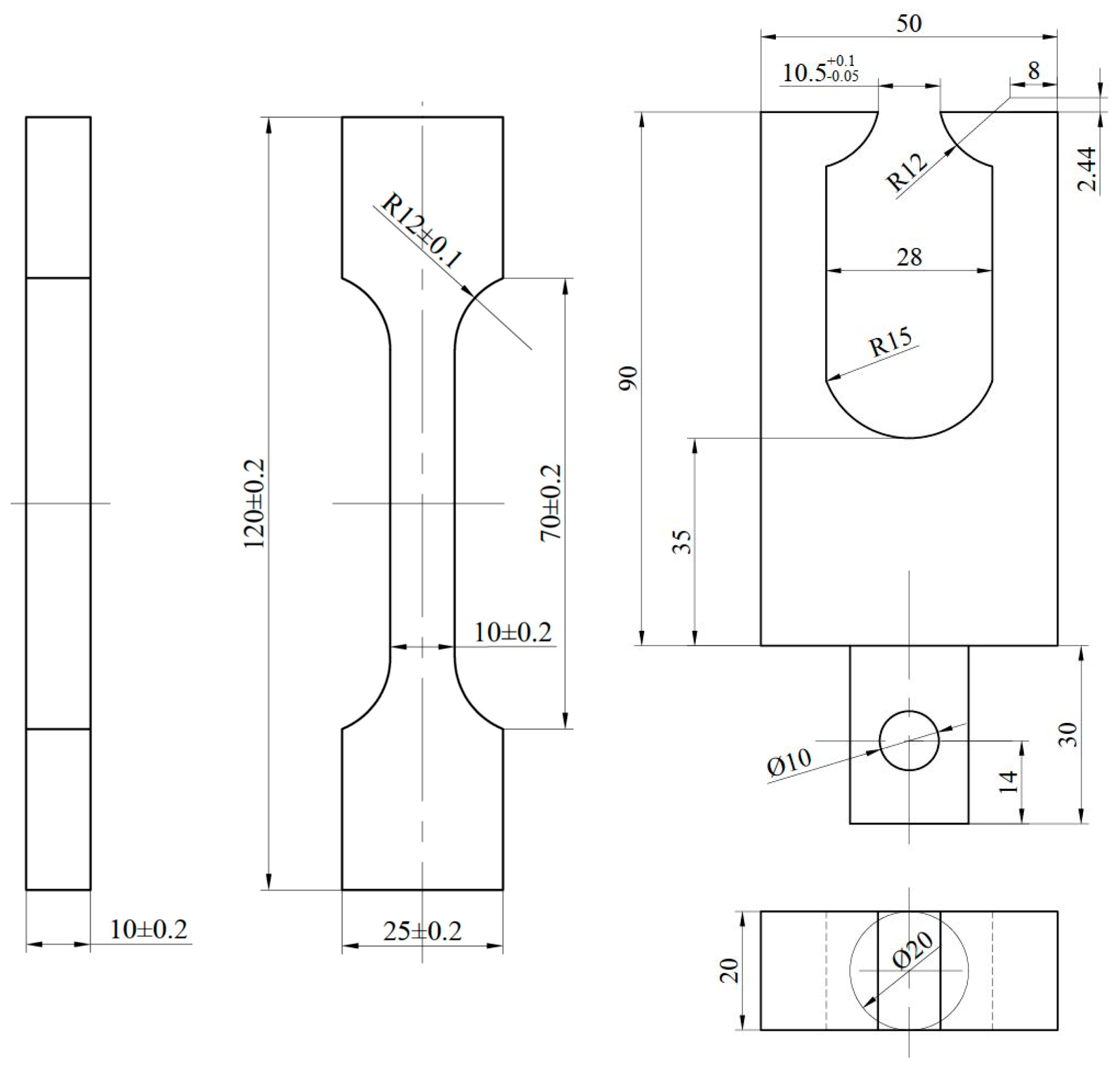
Figure 1. Schematic of specimen geometry and tensile fixture configuration for CMDB propellant testing.
Aerospace 12 00817 g001
Figure 2. Schematic of the experimental setup for uniaxial tensile and stress relaxation testing.
Aerospace 12 00817 g002
Figure 3. Stress–strain responses of the CMDB propellant under varying temperatures and strain rates.
Aerospace 12 00817 g003
Figure 4. Representative stress–strain responses of the CMDB propellant under varying temperatures at a constant strain rate of 6.67 × 10⁻³ s−1.
Aerospace 12 00817 g004
Figure 5. Strain-loading protocol for stress–relaxation testing.
Aerospace 12 00817 g005
Figure 6. Stress–relaxation curves of the CMDB propellant at varying temperatures.
Aerospace 12 00817 g006
Figure 7. Translation process of modulus curves at different temperatures.
Aerospace 12 00817 g007
Figure 8. Time-temperature shift factor.
Aerospace 12 00817 g008
Figure 9. Master curve of relaxation modulus.
Aerospace 12 00817 g009
Figure 10. Schematic of the stress relaxation superposition model.
Aerospace 12 00817 g010
Figure 11. Comparison of constitutive model predictions and experimental data for the CMDB propellant under varying temperatures and strain rates.
Aerospace 12 00817 g011aAerospace 12 00817 g011b
Table 1. Parameters of the constitutive model at 273 K.
Tensile Strain Rate σ r R 1 σ S R 2
3.33 × 10⁻⁴ s−1261.0200.0321.18128.796
1.67 × 10⁻³ s−1227.4060.0351.89720.010
6.67 × 10⁻³ s−13.14618.796315.9210.015
3.33 × 10⁻² s−14.22320.720630.7840.007
1.67 × 10⁻¹ s−14.97518.653741.9320.004
Disclaimer/Publisher’s Note: The statements, opinions and data contained in all publications are solely those of the individual author(s) and contributor(s) and not of MDPI and/or the editor(s). MDPI and/or the editor(s) disclaim responsibility for any injury to people or property resulting from any ideas, methods, instructions or products referred to in the content.