Article

Dynamic Event-Triggered Multi-Aircraft Collision Avoidance: A Reference Correction Method Based on APF-CBF

1
Graduate School, Air Force Engineering University, Xi’an 710038, China
2
Air Defence and Antimissile School, Air Force Engineering University, Xi’an 710038, China
*
Author to whom correspondence should be addressed.
Aerospace 2025, 12(9), 803; https://doi.org/10.3390/aerospace12090803
Submission received: 3 August 2025 / Revised: 2 September 2025 / Accepted: 3 September 2025 / Published: 5 September 2025
(This article belongs to the Special Issue Formation Flight of Fixed-Wing Aircraft)

Abstract

To address the key issues in cooperative collision avoidance of multiple aircraft, such as unknown dynamics, external disturbances, and limited communication resources, this paper proposes a reference correction method based on the Artificial Potential Field-Control Barrier Function (APF-CBF) and combines it with a dynamic event-triggered mechanism to achieve efficient cooperative control. This paper adopts a Fuzzy Wavelet Neural Network (FWNN) to design a finite-time disturbance observer. By leveraging the advantages of FWNN, which integrates fuzzy logic reasoning and the time-frequency locality of wavelet basis functions, this observer can synchronously estimate system states and unknown disturbances, to ensure the finite-time uniformly ultimate boundedness of errors and break through the limitation of insufficient robustness in traditional observers. Meanwhile, the APF is embedded in the CBF framework. On the one hand, APF is utilized to intuitively describe spatial interaction relationships, thereby reducing reliance on prior knowledge of obstacles; on the other hand, CBF is used to strictly construct safety constraints to overcome the local minimum problem existing in APF. Additionally, the reference correction mechanism is combined to optimize trajectory tracking performance. In addition, this paper introduces a dynamic event-triggered mechanism, which adjusts the triggering threshold by real-time adaptation to error trends and mission phases, realizing “communication on demand”. This mechanism can reduce communication resource consumption by 49.8% to 69.8% while avoiding Zeno behavior. Theoretical analysis and simulation experiments show that the proposed method can ensure the uniformly ultimate boundedness of system states and effectively achieve safe collision avoidance and efficient formation tracking of multiple aircraft.

1. Introduction

With the development of aerospace technology, the demand for formation cooperative tasks of multiple fixed-wing aircraft in military, civil, and other fields is increasingly urgent. As a core link to ensure the safe and efficient execution of tasks, the reliability of formation obstacle avoidance directly determines the success or failure of tasks. However, factors such as centralized control methods, external disturbances, limited communication resources, and obstacles may pose threats to the flight safety of aircraft formations. Therefore, the ability of precise obstacle avoidance in complex environments is a key prerequisite for multiple fixed-wing aircraft formations to exert their cooperative value, and its importance is becoming increasingly prominent.
In such tasks, fixed-wing aircraft are required to achieve precise formation tracking in dynamic environments while avoiding obstacles and adjacent aircraft. Currently, the main approaches to solving such problems include the artificial potential field (APF) [1,2,3,4,5,6,7], the control barrier function (CBF) [8,9,10,11,12,13], and path planning methods based on artificial intelligence algorithms [14,15,16,17,18,19,20]. The APF method is the most mature obstacle avoidance algorithm. Due to its low computational complexity and straightforward implementation, this method has been widely used to solve multi-UAV obstacle avoidance problems. Fei et al. [1,2] took the artificial potential field method as the core to design a collision avoidance strategy for multi-robot systems; meanwhile, they generated a new reference trajectory by means of tangential projection of obstacles, realizing the collaborative optimization of system obstacle avoidance and path planning. Pan et al. [3] made in-depth improvements to the artificial potential field method by introducing dynamic adjustment factors, enabling the attractive and repulsive forces to flexibly change according to the real-time distance and relative position between the target point and obstacles, thus effectively alleviating the problems of target inaccessibility and local optimality. Yang et al. [4] addressed the problem of discontinuous derivatives in the traditional artificial potential field method by smoothing the control input to avoid violent movements of the actuator and realized formation and collision avoidance functions through an error conversion function combined with a single type of potential function. Shao et al. [5] proposed a three-dimensional adaptive potential field algorithm based on multi-agent reinforcement learning to tackle the defects of the artificial potential field method in complex scenarios, such as local minima and poor environmental adaptability, innovatively integrating the artificial potential field method with artificial intelligence technology. Antony et al. [6] also addressed the problem that the artificial potential field is prone to falling into local minima and proposed adding a rotational potential field to the artificial potential field, which can handle dynamic obstacle scenarios compared with [2]. Qian et al. [7] focused on the distributed cooperative control challenges of multi-fixed-wing UAVs under external disturbances, system uncertainties, communication link failures, and obstacle avoidance local minima problems and proposed a scheme combining a distributed virtual leader state observer and a virtual agent artificial potential field method: the distributed virtual leader state observer is used to offset the impact of time-varying communication link failures on state transmission, and enhanced APF is used to introduce virtual agents and share obstacle avoidance information to solve the local minima problem of traditional APF. Unfortunately, it can only determine the movement direction based on the resultant potential field force in the current local environment, lacking global environmental information and dynamic adaptability. Moreover, it does not have the capability of trajectory planning, which often leads to energy waste. The CBF method converts safety constraints into an optimization problem with inequality constraints, and it is a commonly used method to solve multi-aircraft collision and obstacle avoidance planning problems. Chen et al. [8] proposed a distributed supervisory control method based on control barrier functions and backup controllers. In cases where the robot’s driving capability is limited, distributed decision-making ensures collision-free operation of the multi-robot system, with safety regions defined by control barrier functions and feasible trajectories generated in combination with backup controllers. Li et al. [9] designed collision avoidance trajectories for spacecraft at the initial stage of movement based on the positional relationships between spacecraft and between spacecraft and obstacles, combined with control barrier functions and quadratic programming; meanwhile, they designed a corresponding event-triggered algorithm to effectively reduce the waste of communication resources and actuator wear. Wu et al. [10] proposed a non-optimization smooth control barrier function method to solve the problems of traditional collision avoidance methods, which are prone to discontinuous control inputs or excessive conservatism when dealing with non-smooth obstacle boundaries and usually require online solution of optimization problems with high computational complexity, making it difficult to meet real-time requirements. Tian et al. [11] improved the barrier Lyapunov function (BLF) by constraining the line-of-sight distance and angle error and designed a relative threshold event-triggered mechanism; the improved barrier Lyapunov function constrains both distance and angle errors but does not consider the problem of actuator output saturation or failure, which may lead to increased tracking errors if the actuator output is limited. Vangasse et al. [12] proposed an integrated framework based on model predictive control (MPC): the velocity and position references of time-varying paths generated by artificial vector fields, together with CBFs as constraints, are embedded into the MPC optimization problem, and the MPC is designed to allow each robot to independently solve quadratic programming problems involving path tracking and collision avoidance constraints through a distributed architecture. Molnar et al. [13] proposed a system based on control barrier functions, but this method has limitations, such as functional constraints of high-order CBFs, large control inputs, difficulty of parameter tuning for model-free CBFs, and failure to formally handle input constraints. Unfortunately, the control barrier function method relies on accurate obstacle information and prior flight information of each aircraft for centralized planning, lacking the real-time performance of the artificial potential field method. With the development of artificial intelligence technology, reinforcement learning (RL), as a method to learn optimal strategies through “agent–environment interaction and trial-and-error”, has shown advantages in adapting to complex dynamic scenarios in collision and obstacle avoidance tasks. Chen et al. [14] proposed an end-to-end planning framework based on safe reinforcement learning, combining multi-agent deep deterministic policy gradient with high-order control barrier functions (HOCBFs), and pointed out that the integration of traditional safety control methods (such as control barrier functions) with reinforcement learning lacks an end-to-end learning mechanism, making it difficult to balance safety and learning efficiency. Nemeth et al. [15] proposed a two-layer design framework that integrates reinforcement learning and centralized collaboration to realize the synergy between individual trajectory autonomy and global collision avoidance. Liao et al. [16] addressed the UAV collision avoidance problem in complex urban low-altitude environments, proposing a UAV collision avoidance control method based on distributed reinforcement learning and aerodynamics to improve traffic flow performance and optimize energy consumption. Seah et al. [17] proposed a multi-UAV traffic planning framework based on deep reinforcement learning, using deep Q-networks to solve multi-UAV path planning and collision avoidance problems and combining hindsight experience replay to improve training stability. Peng et al. [18] proposed a safe optimal guidance framework that integrates high-order control barrier functions and actor–critic reinforcement learning. In the process of intercepting maneuvering targets, mathematical safety constraints are used to ensure collision avoidance, and reinforcement learning is used to optimize guidance performance, achieving the dual goals of safe collision avoidance and optimal interception. Unfortunately, when it comes to collision and obstacle avoidance technologies, reinforcement learning is characterized by long training time and high computational resource consumption; its collision avoidance capability depends on training effects, and it also lacks strong stability proofs [19,20].
Among the existing collision avoidance methods for multiple fixed-wing aircraft, the artificial potential field method is widely applied due to its intuitive principle and low computational complexity. However, it has problems such as being prone to falling into local minima and difficulty in handling complex dynamic constraints. The control barrier function ensures the forward invariance of the system by constructing safety constraints, showing advantages in safety control. Nevertheless, it needs to design adaptive constraint forms in combination with system dynamics, and the definition of the safety set relies on prior knowledge of obstacles, making it difficult to adapt to the actual flight environment where aircraft dynamics are unknown. In addition, the traditional time-triggered communication mechanism is prone to resource waste [21], while the event-triggered mechanism can transmit information on demand. However, in dynamic environments, flexible trigger conditions need to be designed while avoiding Zeno behavior. Meanwhile, unknown parameters and external disturbances in aircraft dynamics further increase the difficulty of control, which requires the design of an efficient observation and compensation mechanism. To address the aforementioned issues, this paper proposes a reference correction method that integrates the APF and CBF methods and combines the dynamic event-triggered mechanism with fuzzy neural approximation technology to achieve safe and efficient collision avoidance for multiple aircraft. The specific research contributions are as follows:
  • Since the Fuzzy Wavelet Neural Network (FWNN) [22] integrates the reasoning ability of fuzzy logic with the time-frequency locality of wavelet basis functions, this paper combines FWNN with a finite-time state observer to design a finite-time state observer based on FWNN. It enhances the system’s robustness by estimating unknown states and disturbances in real time;
  • To achieve safe collision avoidance between multiple aircraft, obstacles, and adjacent aircraft while optimizing trajectory tracking accuracy, this paper embeds the APF into the CBF framework to construct safety constraints and dynamically optimize the trajectory through a reference correction mechanism. After embedding APF into the CBF framework, safety constraint functions are constructed using the potential functions between them, and system safety is achieved by ensuring the satisfaction of the control barrier function. The reference correction mechanism adopts a quadratic programming method to minimize the deviation between the actual trajectory and the reference trajectory under the premise of satisfying safety constraints, thereby dynamically optimizing trajectory tracking accuracy;
  • A dynamic event-triggered mechanism is introduced to adjust the communication frequency dynamically, enabling on-demand communication. Communication is triggered when facing formation changes or during collision avoidance, which reduces resource consumption while avoiding Zeno behavior.

2. Preliminaries

2.1. Fixed-Wing Aircraft Dynamic Model

Building on the fixed-wing aircraft dynamic model used by Liu et al. [23], this paper considers a heterogeneous multi-aircraft formation consisting of N aircraft, where the dynamic equation of the i -th aircraft can be expressed as follows:
V ˙ i = T i D i m i g sin γ i γ ˙ i = L i cos ϕ i m i g cos γ i m i V i ψ ˙ i = L i sin ϕ i m i V i cos γ i x ˙ i = V i cos γ i cos ψ i + d i x y ˙ i = V i cos γ i sin ψ i + d i y z ˙ i = V i sin γ i + d i z
Figure 1 shows the model of a real fixed-wing aircraft during flight. The symbols in the figure and in Equation (1) are expressed as follows: T i represents the thrust; m i is the mass of the fixed-wing aircraft, and D i is the drag force of the fixed-wing aircraft. p i = [ x i , y i ,   z i ] T is the position of the fixed-wing aircraft; v i = p ˙ i = [ v i x , v i y , v i z ] T is the velocity of the aircraft; γ i   is the bank angle; ψ i is the heading angle; ϕ i is the flight path angle; g is the gravitational constant, and d i = [ d i x , d i y , d i z ] T represents the external disturbance. In this paper, the thrust T i and the bank angle ϕ i are selected as the control variables.
u i = [ F x i , F y i , F z i ] T = [ T i D i ,   L i cos ϕ i ,   L i sin ϕ i ] T
Therefore, the velocity state of the i -th fixed-wing aircraft is chosen as v i = p ˙ i = [ v i x , v i y , v i z ] T , and the above-mentioned model can be expressed by the following Equation:
  p ˙ i = v i v ˙ i = B i u i E i + d i
Therefore, the following equation can be obtained:
B i = 1 m i cos γ i cos ψ i sin γ i cos ψ i sin ψ i cos γ i sin ψ i sin γ i sin ψ i cos ψ i sin γ i cos γ i 0
    E i = 1 m i D i cos γ i cos ψ i D i cos γ i sin ψ i D i sin γ i + m i g
d i = d i y V i sin γ i cos ψ i + d i x d i y V i sin γ i sin ψ i + d i y d i y V i sin γ i + d i z
Remark 1.
In the actual flight scenarios of fixed-wing aircraft, the sources of external disturbances exhibit significant complexity and diversity. Specifically, they include not only factors directly related to the flight environment, such as airflow disturbances (e.g., aerodynamic fluctuations caused by gusts and turbulence) and aerodynamic parameter perturbations, but also uncertainties brought about by the simplification of the system model. To achieve effective control of such disturbances  d i = [ d i x , d i y , d i z ] T , they are usually regarded as a whole as an unknown but bounded set; that is, it is assumed that the amplitude of the disturbances is always restricted within a quantifiable interval. By incorporating compensation mechanisms for bounded disturbances, such as robust controllers and disturbance observers, into the control algorithm, it can be ensured that the aircraft can still maintain attitude stability, trajectory tracking accuracy, and flight safety under the action of disturbances, avoiding control mismatch or system divergence caused by the accumulation of disturbances. In the actual aerospace environment, due to the constraints of atmospheric physical characteristics, disturbances such as aerodynamic parameter perturbations, wind shear, and airflow interference necessarily have upper bounds, which have been widely verified and applied in the latest current research [23,24].

2.2. Graph Theory

In this paper, it is assumed that the aircraft in the formation are numbered from 1 to N , and the cooperation of each aircraft only relies on local communication with its adjacent nodes. The communication network of the aircraft cluster is modeled using a directed graph, denoted as G = ( V , , W ) , where the node set V represents the set of all aircraft; the edge set { ( v i , v j ) | v i , v j V } represents the communication connection relationship between aircraft, and the edge i ,   j   belongs to when aircraft i can send information to aircraft j ; the weighted adjacency matrix W = [ w i j ] N × N  is used to describe the weight of communication links, and the weight is a non-zero value if and only if there is a communication edge between nodes; the neighbor set of each node is defined as  N i = { j | ( v j , v i ) } , and the in-degree of a node is d i = j N i w j i , representing the total weight of information received by the node. In addition, the communication topology can also be characterized by its Laplacian matrix L   =   D     W , where D = diag { d 1 , d 2 , , d N } is the degree diagonal matrix. If there is at least one node in the graph that has a directed path to other nodes, the graph G is called a directed graph containing a spanning tree, and this node is called the root node.
Lemma 1  
([25]). If graph G  is strongly connected, and there is at least a non-negative diagonal matrix  G  with a positive element, then  L   +   B  is an irreducible non-singular  M . Let  q = [ q 1 , q 2 , , q N ] T = ( L + B ) 1 . Define the diagonal matrix  P = diag { p 1 , p 2 , , p N } = diag { 1 / q 1 , 1 / q 2 , , 1 / q N } . Evidently, P is a positive-definite matrix. On this basis, construct the matrix Q = P ( L + B ) + ( L + B ) T P . It can be proved that Q is a symmetric matrix and is positive-definite.

2.3. Fuzzy Wavelet Neural Network Approximation

In this study, considering the unknown dynamic characteristics of the aircraft, to ensure the robustness of the system, a neural network is adopted as a commonly used approximation tool to model the unknown dynamics. To further improve the modeling accuracy and generalization ability, researchers combine fuzzy logic rules with neural networks to construct fuzzy-rule-based neural networks (FNNs). Compared with traditional neural network systems, fuzzy neural networks have stronger function approximation ability and better adaptability.
The fuzzy wavelet neural network has become the preferred method for modeling the unknown dynamic characteristics of the aircraft in this study due to its high efficiency and wide application in the field of function approximation. The relevant existing literature [22,26,27,28] has fully verified the superior approximation performance of FWNN when dealing with complex and nonlinear systems.
Compared with conventional neural networks, the fuzzy wavelet neural network not only possesses the self-learning and nonlinear mapping capabilities of neural networks but also incorporates the advantages of local feature extraction of wavelet transforms and the ability of fuzzy logic to handle uncertainty. Therefore, when dealing with the problem of modeling complex and uncertain dynamics, FWNN can exhibit higher precision and stronger robustness, outperforming traditional neural network structures. The structure of FWNN can be described by a set of fuzzy rules: R i : If x 1 belongs to A 1 i ; x 2 belongs to A 2 i , and x n belongs to A 1 n . Let ψ i = Ψ i j = 1 n g j i ( x j ) , where x j represents the j -th input, and Ψ i is the weight coefficient between the i -th output and the j -th input. g j i is a wavelet basis function, defined as g j i ( x j ) = x j c j i s j i , where c j i and s j i are the scaling parameter and translation parameter, respectively. By parameterizing a single mother wavelet function, the output of FWNN can be constructed and is expressed as follows:
ψ ( x ) = i = 1 m μ i ( x ) ψ i i = 1 m μ i ( x )
where μ i ( x ) = j = 1 n A j i ( x j ) is a Gaussian membership function, and A j i ( x j )  is defined as
A j i ( x j ) = exp ( x j b j i ) 2 ( σ j i ) 2
where b j i and σ j i are the center and width parameters of the Gaussian membership function, respectively. Additionally, the wavelet basis function can be expressed as
G ( x ) = 1 | δ | exp ( 1 2 x 2 ) ( 1 2 x 2 )
For any unknown but continuous target function ψ ( x ) , through processes such as singleton fuzzification, product inference, and weighted average defuzzification, it can be guaranteed that there exists a set of optimal weights Ψ N , such that ψ ( x ) = Ψ T G ( x ) + e ψ , where x n  is the input vector,  G ( x ) N  is the basis function vector, and  e ψ is the approximation error satisfying | e ψ | ε ψ with ε ψ 0 . Therefore, in the following, FWNN will be utilized to perform a high-precision approximation of the unknown dynamic characteristics.
Theorem 1.
The optimal weight matrix of the FWNN is bounded, i.e.,  W i < W M a x , where  W M a x  is a positive constant. For the FWNN sliding-mode observer, the upper bound of the disturbance estimation error is solely determined by the approximation error of FWNN. Theoretically, as long as the accuracy of the FWNN is sufficiently high, this upper bound can be arbitrarily reduced, and this conclusion has been proven in the studies of the literature [26,28]. Similarly, the disturbance estimation error satisfies  μ i σ i μ M a x , where μ M is a positive constant.

2.4. Control Barrier Function

The control barrier function is a powerful tool that can effectively ensure safety. The quadratic optimization method based on CBF can coordinate the safety objectives and formation tracking objectives [29,30]. Consider a nonlinear affine system of the following form:
x ˙ = f ( x ) + g ( x ) u  
where x d represents the system state; the mappings f ( x ) : d d and g ( x ) : d d × p are locally Lipschitz continuous functions; u p is the control input. According to [29], let S n  be a set defined by a continuously differentiable function  h : n :
S = { x n : h ( x ) 0 } , S = { x n : h ( x ) = 0 } , I n t ( S ) = { x n : h ( x ) > 0 }
If for all x S   h ( x ) 0 , and there exists an extended class  K  function  α  such that for all  x S , there exists a u satisfying the following:
( L f h ( x ) + L g h ( x ) u h ˙ ( x , u ) α ( h ( x ) )  
where  L f h ( x ) : = h ( x ) T f ( x )   and L g h ( x ) : = h ( x ) T g ( x ) . Then, h is a control barrier function and can be modified into a safety controller via quadratic programming.
k ( x ) = arg min u m u u 0 ( x ) 2

3. Main Results

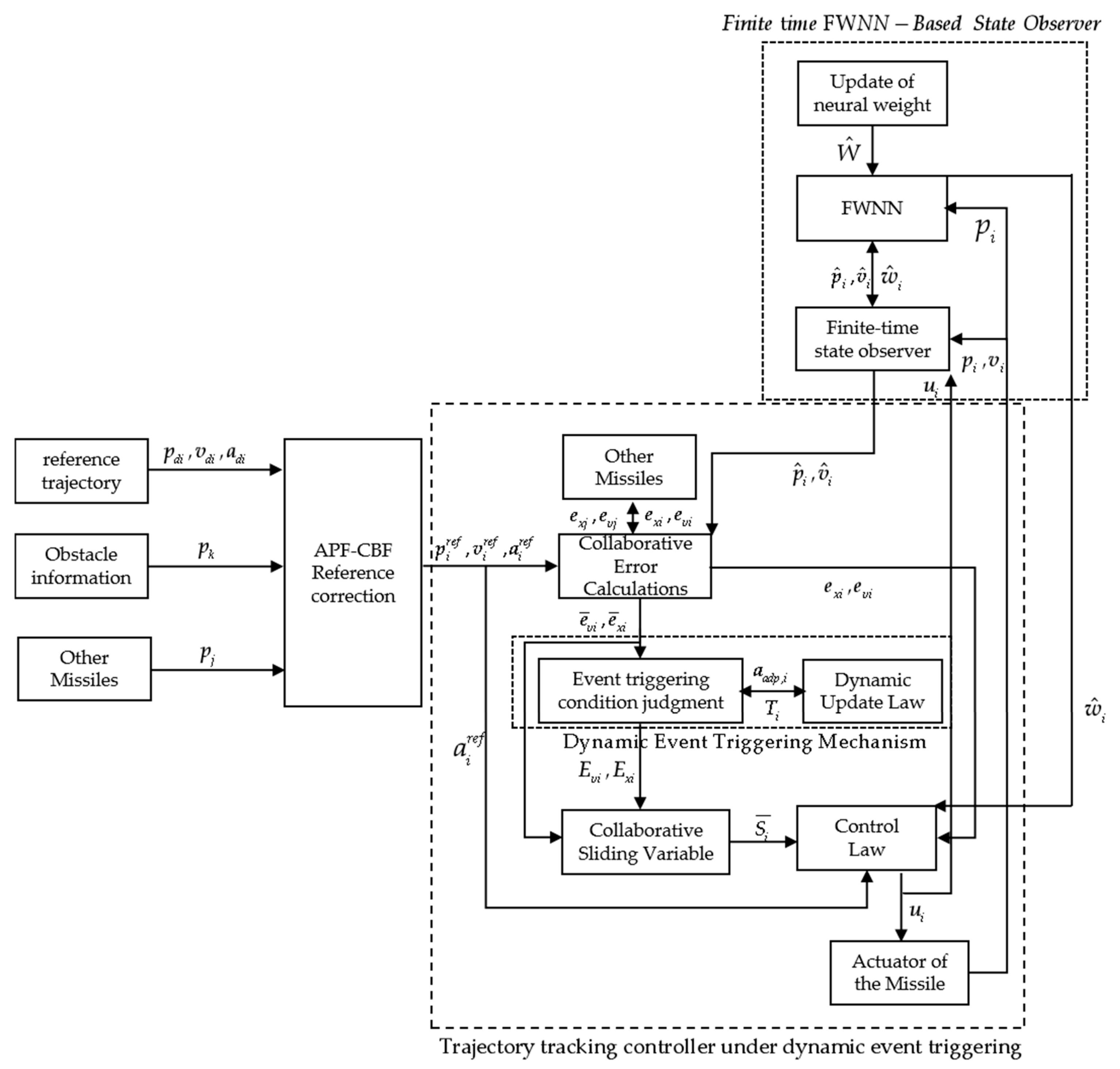
This chapter investigates the collision avoidance control problem for multiple aircraft under a dynamic event-triggered mechanism, with particular focus on trajectory tracking and safe collision avoidance in the presence of aircraft model uncertainties, external disturbances, and overload saturation. In the reference correction algorithm, the artificial potential field-control barrier function framework is integrated to construct safety constraints, and the reference correction mechanism via a quadratic programming algorithm transforms the desired trajectory into an executable reference trajectory that ensures collision avoidance safety. Moreover, a dynamic event-triggered mechanism is incorporated into the tracking controller to dynamically adjust the communication frequency, thereby reducing the communication burden among multiple aircraft while avoiding Zeno behavior. The trajectory tracking controller is responsible for generating control commands based on the executable reference trajectory to regulate the actual motion of the aircraft and ensure tracking accuracy. Additionally, a finite-time convergent disturbance observer based on FWNN is proposed. Leveraging the advantages of FWNN, which combines the reasoning ability of fuzzy logic and the time-frequency locality of wavelet basis functions, it can real-time estimate and compensate for uncertainties and external disturbances in the nonlinear model, enhancing the robustness of the system.

3.1. Finite-Time Disturbance Observer Based on Fuzzy-Wavelet Neural Network

Lemma 2 
([31]). Consider the Lyapunov candidate function  V ( tanh ξ i ( p ^ i ) , σ ˜ i T , W ˜ i T ) ; if its time derivative satisfies the following condition:
V ˙ κ 1 V ξ 1 + κ 2 V ξ 2
where  0 < κ 2 < κ 1 < 1  and  ξ 1 , ξ 2 > 0 , then the error states  tanh ξ i ( p ^ i T ) ,  σ ˜ i , and  W ˜ i  are all finite-time uniformly ultimately bounded (finite-time UUB). The function  V ( tan h ξ 1 ( p ^ T i ) , v ˜ i T , W ˜ i T )  is contained within the following attractive region:
Ω V = ( tanh ξ 1 ( p ^ i T ) , v ˜ i T , W ˜ i T ) | V ( tanh ξ 1 ( p ^ i T ) , v ˜ i T , W ˜ i T ) ξ 2 / ξ 3 κ 1 κ 2
where  ξ 3 ( 0 , ξ 1 ) . Define   t 0  as the initial time instant, then the boundary of the settling time can be expressed as
T V 1 κ 2 ( t 0 ) / ( ξ 1 ξ 3 ) ( 1 κ 1 )
For the i-th aircraft, the dynamic model (4) is obtained. By treating  d i  and  E i  as the disturbances to be observed by the observer, we can derive:
w i = E i + d i
the unknown function  w i  in Equation (17) is approximated by FWNN.
w ^ i   = Ψ T   ϑ   ( y ) + e ( y )
where  y  is the input,  Ψ N 1  is the weight vector, and  ϑ ( y ) [ ϑ 1 ( y ) , ϑ 2 ( y ) , , ϑ N 1 ( y ) ] T N 1  is the basis function vector. The approximation error  e y  satisfies  | e y | e M 0 . The updated law for its weights can be designed as 
Ψ ^ ˙ i = υ φ ( y i ) tanh ξ 1 p ˜ i η tanh ξ 1 p ˜ i Ψ ^ i
Thus, we can design a finite-time state observer based on FWNN. This observer is capable of simultaneously estimating the unknown system states and disturbances, and it has the following form:
p ^ ˙ i = v ^ i + κ 1 tanh ξ 1 ( p ˜ i ) v ^ ˙ i = B i u i + Ψ T   e   ( y i ) + κ 2 tanh ξ 2 ( p ˜ i )  
where  p ^ i n  is the estimated position information;  v ^ i n  is the estimated velocity information;  y i = [ p ^ i T , v ^ i T ] T , and  κ 1 , κ 2 + . Define  H i = [ tanh ξ 1 ( p ^ i T ) , v ^ i T ] T ; then, we can obtain the time derivative of  H i  as follows:
H i . = ξ 1 diag ( | p ˜ i | ξ 1 1 ) ( κ 1 tanh ξ 1 ( p ˜ i ) + v ˜ i ) κ 2 tanh ξ 2 ( p ˜ i ) + 0 w ˜ i = X i A i H i + T w ˜ i
where  p ˜ i = p ^ i p i ,  v ˜ i = v ^ i v i ,  Ψ ˜ i = Ψ ^ i Ψ i ,  A = κ 1 ξ 1 I n ξ 1 I n ξ 1 I n 0 n × n  and  T = 0 n × n I n .
Lemma 3.
If A  is a Hurwitz matrix, then there always exists a symmetric positive-definite matrix    P  such that  A T P + P A = Q , where  Q  is a symmetric positive-definite matrix.
Theorem 2.
Consider the i-th aircraft. Assuming that Assumption 1 holds, the update law of the fuzzy neural network is selected as such, and the parameters are reasonably selected under the constraint conditions  κ 1 , κ 2 > 0 ,   0.5 < ξ 1 < 1 , and  ξ 2 = 2 ξ 1 1 ; then the neural network-based observer can ensure that  Ψ ˜  is uniformly ultimately bounded (UUB), and  H i  is finite-time uniformly ultimately bounded (finite-time UUB).
Proof. 
Find the characteristic polynomial of matrix  A :
det ( λ I A ) = λ 2 + κ 1 ξ 1 λ + κ 2 ξ 1
 we define the following Lyapunov candidate function  V c :
V 1 = 1 2 H i T P H i + 1 2 tr Ψ ˜ i T Ψ ˜ i
according to Lemma 3, the time derivative of  V 1  is derived as follows:
V ˙ 1 = 1 2 H i T X i ( A T P + P A ) H i H i T P T w ˜ i tr Ψ ˜ i T Ψ ^ ˙ i = H i T X i Q H i H i T P T Ψ ˜ i T ϑ   ( y i ) + e ( y i ) + υ tr Ψ ˜ i T Ψ i T ϑ ( y ) [ I n , 0 n ] H i T + η tr Ψ ˜ i T [ I n , 0 n ] H i Ψ i Ψ ˜ i
according to Lemma 3, we obtain the inequality:  tr Ψ ˜ i ( Ψ i Ψ ˜ i ) Ψ M Ψ ˜ i Ψ ˜ i 2 Ψ i Ψ M ,  and  e ( y i ) e M ; then we can get 
V ˙ 1 1 2 H i T X i Q H i H i T P T w ˜ i + υ tr Ψ ˜ i T Ψ i T ϑ ( y ) [ I n , 0 n ] H i T + η tr Ψ ˜ i T [ I n , 0 n ] H i Ψ i Ψ ˜ i 1 2 σ _ ( Q ) H i 1 1 / ξ 1 H i 2 + [ σ ¯ ( P ) e M + χ Ψ ˜ i ] H i + η [ I n , 0 n ] Ψ M Ψ ˜ i 2 ) H i 1 2 σ _ ( Q ) H i 3 1 / ξ 1 + χ Ψ ˜ i H i   + σ ¯ ( P ) e M H i η H i Ψ ˜ i 2 l T Ξ l + H l
where
χ = e M max ( | σ ¯ ( P T + υ [ I n , 0 n ] ) | , | σ _ ( P T + υ [ I n , 0 n ] ) | ) + η Ψ M
l = H i Ψ ˜ i , H = σ ¯ ( P ) e M 0 Ξ = σ _ ( Q ) H i 1 1 / ξ 1 / 2 χ / 2 χ / 2 η H i
It can be seen from the above formula that the positive definiteness of matrix Ξ  is determined by the value of  det ( Ξ ) = σ _ ( Q ) η H i 2 1 / ξ 1 / 2 χ 2 / 4 . To make  Ξ  positive definite and thereby further ensure the convergence of  H i , the parameters  ν  and  η  in the update law need to be sufficiently large.
Consider another function  V H , which is defined as follows:
V H = 1 2 H i T P H i
If we have  W ˜ F W ˜ M , then we can further obtain:
V ˙ H = 1 2 H i T X i ( A T P + P A ) H i H i T P T w ˜ i = 1 2 H i T X i Q H i H i T P T Ψ ˜ i T ϑ   ( y i ) + e ( y i ) 1 2 σ _ ( Q ) H i 3 1 / ξ 1 +   ( σ ¯ ( P ) e M + σ ¯ ( P T ) Ψ ˜ M e M ) H i
According to the inequality  σ _ ( P ) H i 2 / 2 V H σ ¯ ( P ) H i 2 / 2 , we have:
V ˙ H σ ¯ ( P ) / 2 ( 1 3 ξ 1 ) / ( 2 ξ 1 ) σ _ ( Q ) / 2 V H ( 3 ξ 1 1 ) / ( 2 ξ 1 ) +   ( σ ¯ ( P ) e M + σ ¯ ( P T ) Ψ ˜ M e M ) 2 / σ _ ( P ) 1 / 2 V H 1 / 2
According to Lemma 2, the error vector  H i  of the proposed observer (10) is finite-time uniformly ultimately bounded (finite-time UUB). Thus, the proof is completed. □

3.2. Reference Trajectory Correction Based on APF–CBF

To achieve obstacle avoidance and mutual collision avoidance among aircraft, this paper first uses the artificial potential field to assign a potential function and the gradient of the potential function to each obstacle. This can further integrate the control barrier function, and according to the quadratic programming algorithm, the reference path of the aircraft is corrected in real time.
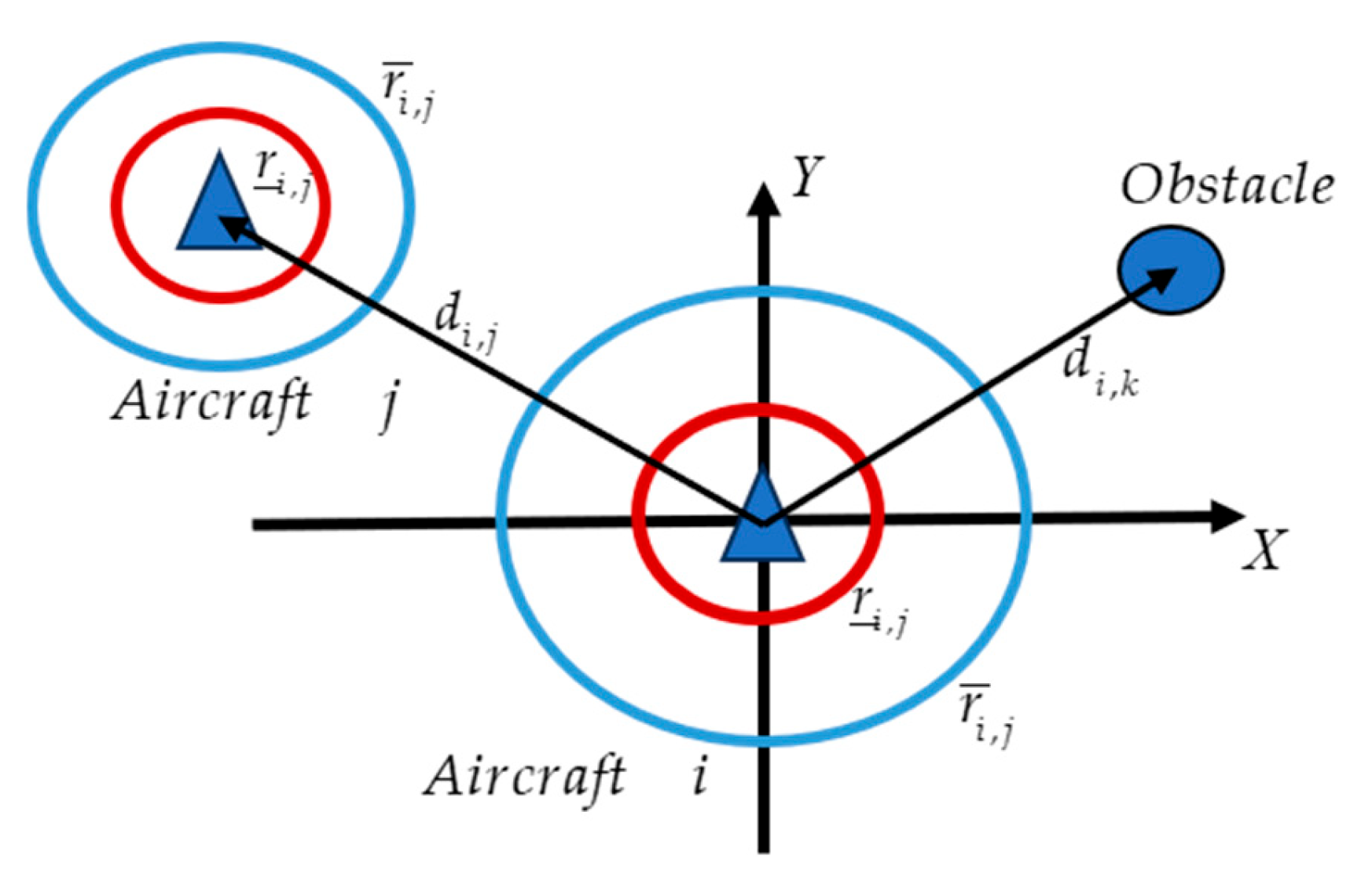
It is assumed that there are fixed obstacles in the operating space of the multi-aircraft formation. An obstacle can be described as an element in O = ( p o , r o ) , where p o represents the Cartesian coordinate position of the center of the obstacle, and r o is the radius of the obstacle. d i , k = p i p o = p i p o   represents the relative position vector between the i -th aircraft and the obstacle. Define d i , j as the relative position vector between the i -th aircraft and the j -th aircraft, which can be expressed as d i , j = p i p j = p j p i . The positional relationship among them can be shown in Figure 2.
Now, we are ready to define the repulsive potential function Φ ( d i , j ) between the i -th and the j -th aircraft, as well as the repulsive potential function Φ ( d i , k ) between the i -th aircraft and the obstacle. Φ ( d i , j ) and Φ ( d i , k ) are differentiable and monotonically decreasing functions, satisfying the following conditions:
1.
When d i , j r _ i , j or d i , k r _ i , k , Φ ( d i , j ) +  or  Φ ( d i , k ) + . Here, r _ i , j = ϵ min ( r i + r j ) is the minimum safe distance between aircraft ( i , j ) , and r _ i , k = ϵ min ( r i + r o ) is the minimum safe distance between the center of the i -th aircraft and the center of the obstacle. ϵ min is a constant, satisfying ϵ min > 1 ;
2.
When d i , j r ¯ i , j or d i , k r ¯ k , Φ ( d i , j ) 0 or Φ ( d i , k ) 0 . When d i , j r ¯ i , j , Φ ( d i , j ) = 0 ; when d i , k r ¯ i , k , Φ ( d i , k ) = 0 . Here, r ¯ i , j = ϵ max ( r a , i + r a , j ) represents the outer boundary of APF. ϵ max is a constant satisfying ϵ max > ϵ min  and  r ¯ i , j < x d , i x d , j .
Let the combined gradient between the i -th and the j -th aircraft be expressed as j N i z i , j Φ ( d i , j ) , where N i is the neighbor set of the i-th aircraft in graph G. The gradient between the i -th aircraft and the obstacle is Φ ( d i , k ) .
Φ ( d i , j ) = ln d i , j r _ i , j r ¯ i , j r _ i , j + r ¯ i , j d i , j d i , j r _ i , j ,   d i , j ( r _ i , j , r ¯ i , j ] 0 , otherwise .
correspondingly, the gradient can be expressed as
Φ ( d i , j ) = d i , j r ¯ i , j d i , j r _ i , j 2 d i , j d i , j , d i , j ( r _ i , j , r ¯ i , j ] 0 , otherwise .
Define Δ r i , k = r ¯ i , k r _ i , k to represent the width of the potential field. Then, according to Definition 2, the artificial potential function between the i -th aircraft and the obstacle is selected as follows:
Φ ( d i , k ) = ln d i , k r _ i , k Δ r i , k + r ¯ i , k d i , k d i , k r _ i , k ,   d i , k ( r _ i , k , r ¯ i , k ] 0 , otherwise
we can obtain the gradient generated by the artificial potential field, as shown in the following formula:
d i , k Φ ( d i , k ) = α d i , k r ¯ i , k d i , k r _ i , k 2 d i , k d i , k ,   d i , k ( r _ i , k , r ¯ i , k ] 0 , otherwise
the control barrier function incorporates such an artificial potential field as a special case, consider an artificial potential field with a repulsive force potential Φ ( d i , j ) + Φ ( d i , k ) .
h ( d i , j , d i , k ) = 1 1 + Φ ( d i , j ) + Φ ( d i , k ) δ
where δ ( 0 , δ 0 ) is a small constant, we can obtain the following conclusion:
h ˙ ( d i , j , d i , k , v ) = h ( d i , j , d i , k ) T v α ( h ( d i , j , d i , k ) )
Among them S = d i , j , d i , k n : h ( d i , j , d i , k ) 0 , is safe and asymptotically stable. Therefore, the smaller  δ  is chosen, the closer the safe set S is to the complement of the obstacle. In addition, different from the potential field, when the system starts from the initial conditions outside S, the control barrier function can still be well-defined, and the system will asymptotically stabilize back to S.
For the aircraft dynamics model (3), the requirement of the given CBF can be easily satisfied. Because L h ( d i , j , d i , k ) = h ( d i , j , d i , k ) T v , there always exists a velocity v such that:
( Φ ( d i , j ) + Φ ( d i , k ) ) v ( 1 + Φ ( d i , j ) + Φ ( d i , k ) ) 2 α ( h ( d i , j , d i , k ) )
the desired final v i r e f vcan be obtained via the quadratic programming algorithm.
v i r e f = argmin v n v v d 2 s . t . ( Φ ( d i , j ) + Φ ( d i , k ) ) v ( 1 + Φ ( d i , j ) + Φ ( d i , k ) ) 2 α ( h ( d i , j , d i , k ) )
The obstacle-avoidance algorithm with APF-CBF reference correction proposed in this chapter is presented in Algorithm 1.
Algorithm 1: APF-CBF Based Reference Correction Algorithm
Input:  p i   , p j   , p k   , v d i   , p d i   , a d i  
Output:  p i r e f , v i r e f , a i r e f
Obtain the information of the nearest obstacle and the positions of neighboring aircraft, and compute the artificial potential fields between them along with their gradient.
Φ ( d i , j ) + Φ ( d i , k ) ; Φ ( d i , j ) + Φ ( d i , k )
if   Φ ( d i , j   ) + Φ ( d i , k   ) = 0  then
p i r e f = p d i ; v i r e f = v d i ; a i r e f = a d i ;
else
 Compute the control barrier function (CBF) h ( Φ ( d i , j ) + Φ ( d i , k ) and its gradient h ( Φ ( d i , j ) + Φ ( d i , k ) .
v i r e f = a r g m i n ( v i r e f v d i ) 2
 s.t.  h ( Φ ( d i , j + Φ ( d i , k ) ) + h ( Φ ( d i , j + Φ ( d i , k ) ) > 0 ;
 Through the quadratic programming (QP) method, as well as integration and differentiation, they can be obtained respectively: p i r e f , v i r e f , a i r e f
return  p i r e f , v i r e f , a i r e f ;

3.3. Formation Tracking Controller-Based on Dynamic Event-Triggered Mechanism

On the basis of the work by Fei et al. [32] and Li et al. [24], according to the aircraft dynamics Equation (3), which gives the position p i and velocity vector v i of the aircraft, the desired trajectory and desired velocity vector for the i -th aircraft are defined as p d i and v d i , respectively. Then, the position error vector and the velocity error vector can be expressed as
e p i = p i p d i e v i = v i v d i
To reduce the consumption of communication resources, a dynamic event-triggered mechanism is introduced in the generation process of the reference trajectory. According to the description of the distributed event-triggered control, the trigger time sequence { t 1 i , t 2 i , , t k i } for its information update is defined. Since each aircraft cannot obtain the real-time state information of its neighbors, data update can only be carried out at the trigger times. To compare the differences between the time-triggered and event-triggered strategies, the following state measurement errors, E p i , E v i , and the state measurement errors under event triggering, e p i ( t k i ) , e v i ( t k i ) , are defined:
E p i = e p i e p i ( t k i ) E v i = e v i e v i ( t k i )
e p i ( t k i ) = p ^ i ( t k i ) p i r e f ( t k i ) e v i ( t k i ) = v ^ i ( t k i ) v i r e f ( t k i )
By integrating the position tracking error formula of the i-th aircraft, the velocity tracking error expression (30), and the dynamics Equation (3) of the aircraft, the dynamics Equation (30) describing the dynamics of the tracking error is rigorously derived:
e ˙ p i = e v i , e ˙ v i = B i u i + w ^ i a i ref
in the multi-aircraft system, for an aircraft and its adjacent aircraft, the tracking error and derivation of local information are as follows:
e ¯ p i = j N i e p i e p j + b i e p i e ¯ v i = j N i e v i e v j + b i e v i
therefore, according to the definitions e ¯ p = [ e ¯ p 1 , e ¯ p 2 , , e ¯ p N ] T and e ¯ v = [ e ¯ v 1 , e ¯ v 2 , , e ¯ v N ] T , it can be derived that
e ¯ p = ( L + B ) I N e ¯ p i e ¯ v = ( L + B ) I N e ¯ v i
combined with the measurement error under the triggering condition (13), the following cooperative triggering error can be defined as
e ˜ p i = e ¯ p i + i N i E p i e ˜ v i = e ¯ v i + i N i E v i
the expression of the virtual sliding mode surface can be derived as follows:
s ¯ i = e ¯ v i + Λ e ¯ p i = e ¯ v i + Λ e ¯ p i
where Λ 1 = [ λ 11 , λ 12 , , λ 1 n ] , the derivative of the virtual sliding mode surface can be derived in the following manner:
s ¯ ˙ i = e ¯ ˙ v i + Λ i e ¯ v i
Equations (17) and (23) denote the Kronecker product, and L denotes the global Laplacian matrix. Then, the virtual sliding mode surface S ˜ i   of the i -th aircraft under the event-triggered mechanism, and the global virtual sliding mode surface S ˜ are given in the following manner:
S ˜ i   = e ˜ v , i + Λ i e ˜ p , i ,
S ˜ = S + A I N E v + Λ i A I N E p
based on the above-mentioned designs of the position tracking error, velocity tracking error (30), and sliding mode variable (40), we can derive the design of the trajectory tracking controller as follows:
u i = B i 1 ( a i r e f w ^ i Λ 1 e v i ( t k i ) h i e p i ( t k i ) q i S ˜ i )
where  q i , h i are both diagonal positive definite matrices, and the trigger conditions are constructed as follows:
t k + 1 i = inf { t > t k i : T i ( E p i , E v i , w ^ i ) u a d p , i > 0 }
where  T i ( E p i , E v i , w ^ i )  is defined as
T i ( E p i , E v i , w ^ i ) = σ _ ( N ) σ _ ( Q ) σ _ ( A ) / 2 E v i 2 + 3 σ _ ( Γ ) σ _ ( H ) σ _ ( Λ ) σ _ ( A ) E p i 2 + w ^ i 2 / 2
where  u adp , i  is defined as  u ˙ a d p , i = ν u a d p , i T i ( E p i , E v i , w ^ i ) + J i , ν and J i are positive constants.
Assumption 1.
During the actual flight of the fixed-wing aircraft, the position error variable  e ¯ p i , the velocity error variable  e ¯ v i , as well as the desired trajectory  p i r e f  and its corresponding desired velocity  v i r e f , all satisfy the conditions of being essentially bounded and Lipschitz-continuous.
Theorem 3.
For the tracking controller (24) of the i-th aircraft, its reference trajectory  p i ref  and reference velocity  v i r e f  satisfy Assumption 1. Through the dynamic event-triggered mechanism (25), if  σ _ ( N ) σ _ ( Q ) > 3 / 2 , σ _ ( Γ ) σ _ ( H ) σ _ ( Λ ) > 0 , ν > 0  are satisfied and condition (28) is met, then  e ¯ x , e ¯ v , and  S ¯  are uniformly ultimately bounded (UUB).
Proof. 
Consider the following Lyapunov candidate:
V 2 = 1 2 S ˜ T P I 3 S ˜ + 1 2 e ¯ p T ( P H ) I 3 e ¯ p + u a d p
 the time derivative of the Lyapunov candidate is
V ˙ 1 = S T P I 3 S ˙ + e ¯ p T ( P H ) I 3 e ¯ ˙ p + i = 1 N u ˙ a d p , i = S T P I 3 e ¯ ˙ p + Λ 1 I 3 e ¯ v + e ¯ p T ( P H ) I 3 S ( Λ 1 I 3 ) e ¯ p i + i = 1 N u ˙ a d p , i = S T P ( L + B ) I 3 e ˙ x + Λ 1 I 3 e ¯ v + e ¯ p T ( P H ) I 3 S e ¯ p T ( P H Λ 1 ) I 3 e ¯ p i + i = 1 N u ˙ a d p , i = S T P ( L + B ) I 3 B i u i + w ^ i u i r e f + Λ 1 I 3 e ¯ v + e ¯ p T ( P H ) I 3 S e ¯ p T ( P H Λ 1 ) I 3 e ¯ p i + i = 1 N u ˙ a d p , i = S T P ( L + B ) I 3 w ^ i Q S Q A I 3 E v Q A Λ 1 I 3 E p e p + e ¯ p T ( P H ) I 3 S e ¯ p T ( P H Λ 1 ) I 3 e ¯ p i + i = 1 N u ˙ a d p , i = S T N w ^ i S T N Q S S T N Q A E v S T N Q A Λ 1 E p S T N w ^ i + e ¯ p T ( P H ) I 3 S e ¯ p T ( P H Λ 1 ) I 3 e ¯ p i + i = 1 N u ˙ a d p , i
 according to Young’s inequality, it can be obtained that
S T N Q A E v S i 2 / 2 + N Q A E v 2 / 2 S T N Q A Λ E p S i 2 / 2 + N Q A Λ E p 2 / 2 S T N w ^ i S i 2 / 2 + N w ^ i 2 / 2
thus, we can obtain this form:
V ˙ 1 3 S i 2 / 2 + N Q A E v 2 / 2 + N Q A Λ 1 E p 2 / 2 + N w ^ i 2 / 2 Γ H Λ 1 e ˜ p 2 + 3 Γ H Λ 1 A E p 2 σ _ ( N ) σ _ ( Q ) S i 2 + i = 1 N u ˙ a d p , i σ _ ( N ) σ _ ( Q ) σ _ ( A ) / 2 E v 2 + σ _ ( N ) w ^ i 2 / 2 ( σ _ ( N ) σ _ ( Q ) 3 / 2 ) S i 2 + 3 σ _ ( Γ ) σ _ ( H ) σ _ ( Λ 1 ) σ _ ( A ) E p 2 σ _ ( Γ ) σ _ ( H ) σ _ ( Λ 1 ) e ˜ p 2 + i = 1 N ( ν u a d p , i T i ( E p i , E v i , w ^ i ) + J i )
The following conclusions can be drawn:
J i < ( σ _ ( N ) σ _ ( Q ) 3 / 2 ) S M a x , i 2 + σ _ ( Γ ) σ _ ( H ) σ _ ( Λ ) e ˜ M a x , i 2 + i = 1 N ν u M a x , a d p , i
where  S i     S M a x , i , e ˜ x     e ˜ M a x , i  and  u a d p , i u M a x , a d p , i .
From the above stability proof, it can be obtained that  S ˜  will ultimately converge, and e ¯  will also converge. Therefore, in accordance with the definition of the uniformly ultimately bounded (UUB) function and the variation in ultimately bounded functions, this indicates that the designed scheme can achieve the convergence of the virtual tracking error. Subsequently, to prove that the dynamic event-triggered mechanism does not exhibit Zeno behavior, for the trigger time interval from to (i.e., the time required for triggering from 0 to  t l o w i ), we can derive the following:
T i ( E p i , E v i , w ^ i ) p E p i 2 + v E v i 2 + w w ^ i 2 p E p i + v E v i + w w ^ i 2
t k t k + 1 p E p , i + v E v , i + w ω ^ i d τ = J i 1 + ν i
t k + 1 i t k i t l o w i = J i 1 + ν i / p V M a x , i + v a M a x , i + w w M a x , i > 0
Analyze the characteristics of the time derivative within a certain time interval:
d d t E v , i a i v ˙ ( t k i ) a i a M a x , i d d t E p , i i x ˙ ( τ k ) v i V M a x , i
based on the above-mentioned boundedness of disturbances and the finiteness of observed values, it can be known that there is no Zeno behavior in the designed dynamic event-triggered mechanism within this controller. □
Remark 2.
For the parameters designed in the above-mentioned dynamic event-triggered mechanism and its update rules (25), (26), and (27), the speed of event-trigger interval transition can be adjusted by tuning these parameters: The variation in  ν   will affect the convergence speed of  u a d p , i . Thus, increasing  ν  can lead to an increase in the number of triggers;  J i  is used to adjust the trigger threshold. When  J i  increases, it results in a decrease in the number of triggers.
Remark 3.
During the actual flight process, the mass of the aircraft [23,24,33,34,35,36] changes with fuel consumption. However, these changes are within a certain range and are negligible. Especially in the short-to-medium-term flight missions of the aircraft, the impact of the mass change caused by fuel consumption on the overall dynamic characteristics is relatively limited. In addition, the designed algorithm has robustness and can adapt to change in mass  m i . The change in mass  m i  can be classified into the category of system uncertainties and compensated for by the designed FWNN state observer.
Remark 4.
When there exists bounded noise in the output signal, it will cause actuator deviation, which, in turn, leads to a discrepancy between the actual flight dynamics characteristics and the desired ones. Such deviations can be incorporated into the system disturbance term  d i = [ d i x , d i y , d i z ] T  and observed and fed back by the finite-time FWNN state observer proposed in this paper. Meanwhile, due to the robustness of the designed controller, the impact caused by the bounded noise in the output signal can be neglected in actual flight.
The block diagram of the multi-aircraft collision-avoidance and tracking control under the dynamic event-triggered mechanism proposed in this paper is shown in Figure 3.

4. Simulation Results and Discussion

To verify the performance of the proposed multi-aircraft collision-avoidance and tracking controller under the dynamic event-triggered mechanism, simulation experiments are conducted specifically on the multi-aircraft system. The hardware environment for the simulation experiments in this study is configured with an Intel Core i7-13700K processor and 32 GB DDR5-5600 memory, while the simulation software adopted is MATLAB R2024a. In experiments, four types of homogeneous aircraft are selected, whose dynamic models are given by Equation (1), and the system parameters are detailed in Table 1.
The masses (kg) of the aircraft are 200, 203, 198, and 204. The gravity is constant at  g = 9.8   m / s 2 . The communication topology of the system is shown in Figure 4. The position of the obstacle is set as    6000 ,   50 ,   80 with a radius of  15   m . The reference trajectories, positions, and velocities of the aircraft are as follows:
p d 1 = 200 t , 150 , 0 T , 0 t < 10 , 200 t , 50 + 100 e ( t 10 ) , 50 + 50 e ( t 10 ) T , 40 > t 10 , 200 t , 10 + 40 e ( t 40 ) , 10 40 e ( t 40 ) T , t 40 ,  
p d 2 = 200 t , 50 , 0 T , 0 t < 10 , 200 t , 50 , 50 + 50 e ( t 10 ) T , 40 > t 10 , 200 t , 10 + 40 e ( t 40 ) , 10 + 40 e ( t 40 ) T , t 40 ,  
p d 3 = 200 t , 50 , 0 T , 0 t < 10 , 200 t , 50 , 50 + 50 e ( t 10 ) T , 40 > t 10 , 200 t , 10 40 e ( t 40 ) , 10 + 40 e ( t 40 ) T , t 40 ,  
p d 4 = 200 t , 150 , 0 T , 0 t < 10 , 200 t , 50 100 e ( t 10 ) , 50 + 50 e ( t 10 ) T , 40 > t 10 , 200 t , 10 40 e ( t 40 ) , 10 40 e ( t 40 ) T , t 40 ,  
Regarding the uncertainties and disturbances of the system, they are set as follows:
d i x = 3 sin ( 0.3 t + i π / 6 ) d i y = 4 cos ( 0.4 t + i π / 6 ) d i z = 5 sin ( 0.5 t + i π / 6 )
In this paper, the parameter selections for the APF-CBF reference correction algorithm, the FWNN state observer, and the tracking controller under the dynamic event-triggered mechanism are shown in Table 2.
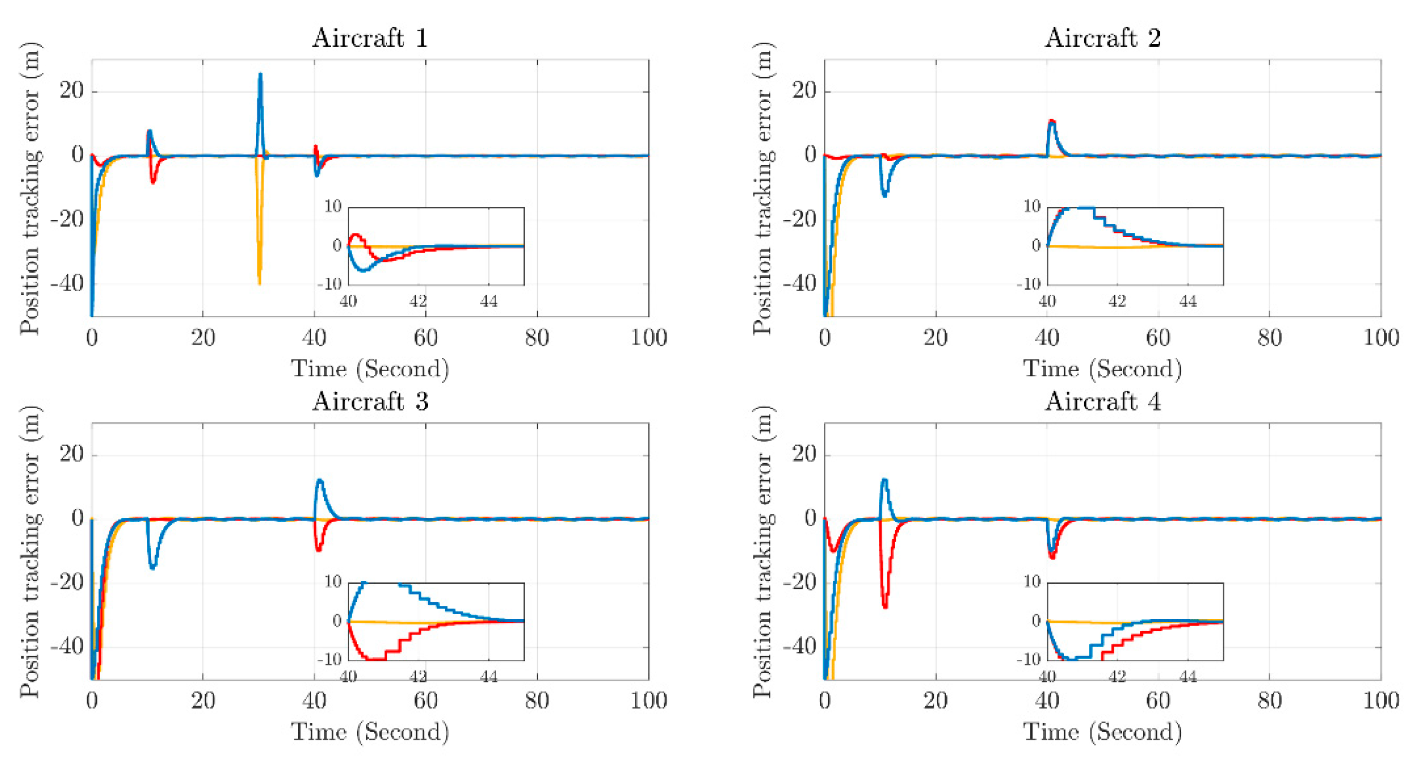
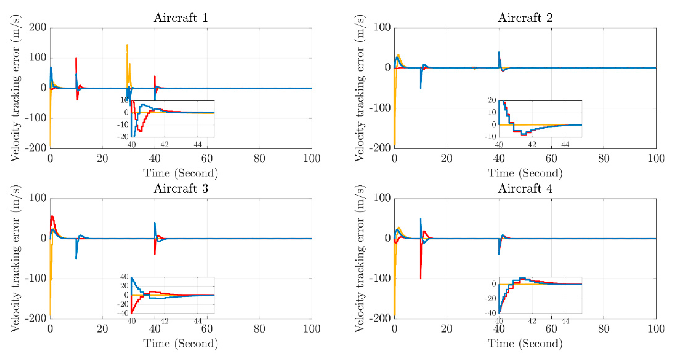
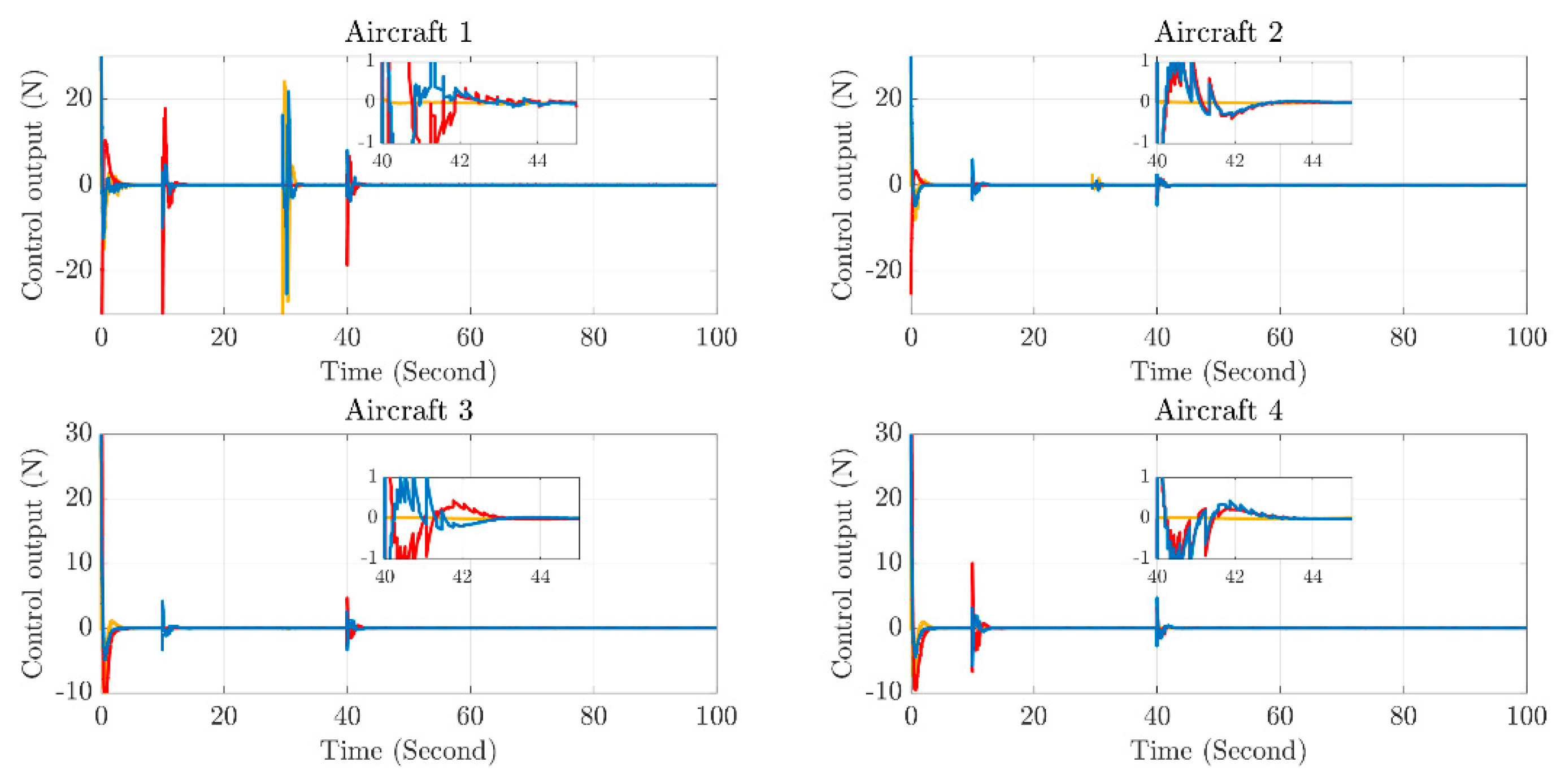
To verify the effectiveness of the trajectory tracking controller under the designed dynamic event-triggered mechanism, simulations are carried out based on the typical mission scenarios of multi-aircraft formation (trajectory tracking, formation transformation, and obstacle-avoidance coordination). The performance of the algorithm is verified through the position tracking error diagram (Figure 5), the velocity tracking error diagram (Figure 6), and the control output diagram (Figure 7).
  • Trajectory initial tracking stage (0–10 s): The position and velocity tracking errors converge rapidly for the first time within 0–10 s. This indicates that the trajectory tracking controller under the dynamic event-triggered mechanism can drive the aircraft to rapidly approach the initial reference trajectory. The convergence speed meets the basic requirements for the timeliness of formation cooperative response, ensuring the rapid alignment of the initial configuration of the multi-aircraft formation;
  • Formation transformation stage (10–30 s): The second error convergence process corresponds to the formation transformation task of the aircraft formation. The controller adjusts the output in real-time, so that the aircraft can still converge rapidly to the new reference trajectory after the task switch, verifying the algorithm’s dynamic response capability to formation transformation commands;
  • Obstacle-avoidance coordination stage (30–40 s): The third error convergence is coupled with the obstacle-avoidance task. When the aircraft avoids virtual obstacles, the position and velocity errors converge rapidly after short-term fluctuations. Even under the influence of obstacle-avoidance path adjustments, the tracking stability can still be maintained;
  • Composite task stage (40–100 s): The fourth convergence corresponds to the composite task of “obstacle-avoidance coordination after the second formation transformation”. Under multiple constraints and multiple objectives, the errors still stably converge to a very small range. This proves that the controller can adapt to complex task scenarios and ensure the formation coordination accuracy.
After the convergence of each stage, both the position error and the velocity error approach zero. The controller can still balance the communication overhead and control precision through the dynamic event-triggered mechanism, maintain a low steady-state error, and verify the high-precision tracking capability and robustness of the algorithm.
The dynamic event-triggered mechanism reduces the data interaction frequency through “communication on demand”. From the morphology of the error curves, it can be seen that despite the decrease in the communication trigger frequency (especially in the steady-state tracking stage), the position and velocity errors of the four aircraft still stably converge instead of diverging. Combining with the control output curve in Figure 7, under the event-triggered logic, the controller only triggers communication and control updates when the error exceeds the threshold. This not only reduces the redundant communication load of the formation system but also ensures the tracking accuracy through precise control commands. This indicates that the mechanism achieves the coordination of communication overhead optimization and tracking performance guarantee. The trajectory tracking controller under the dynamic event-triggered mechanism can be adapted to complex task scenarios such as multi-aircraft formation trajectory tracking, formation transformation, and obstacle-avoidance coordination. It guarantees the timeliness of task response through the fast convergence characteristics in multiple stages, meets the coordination accuracy requirements with high-precision steady-state tracking, and significantly reduces communication overhead by means of the event-triggered logic.
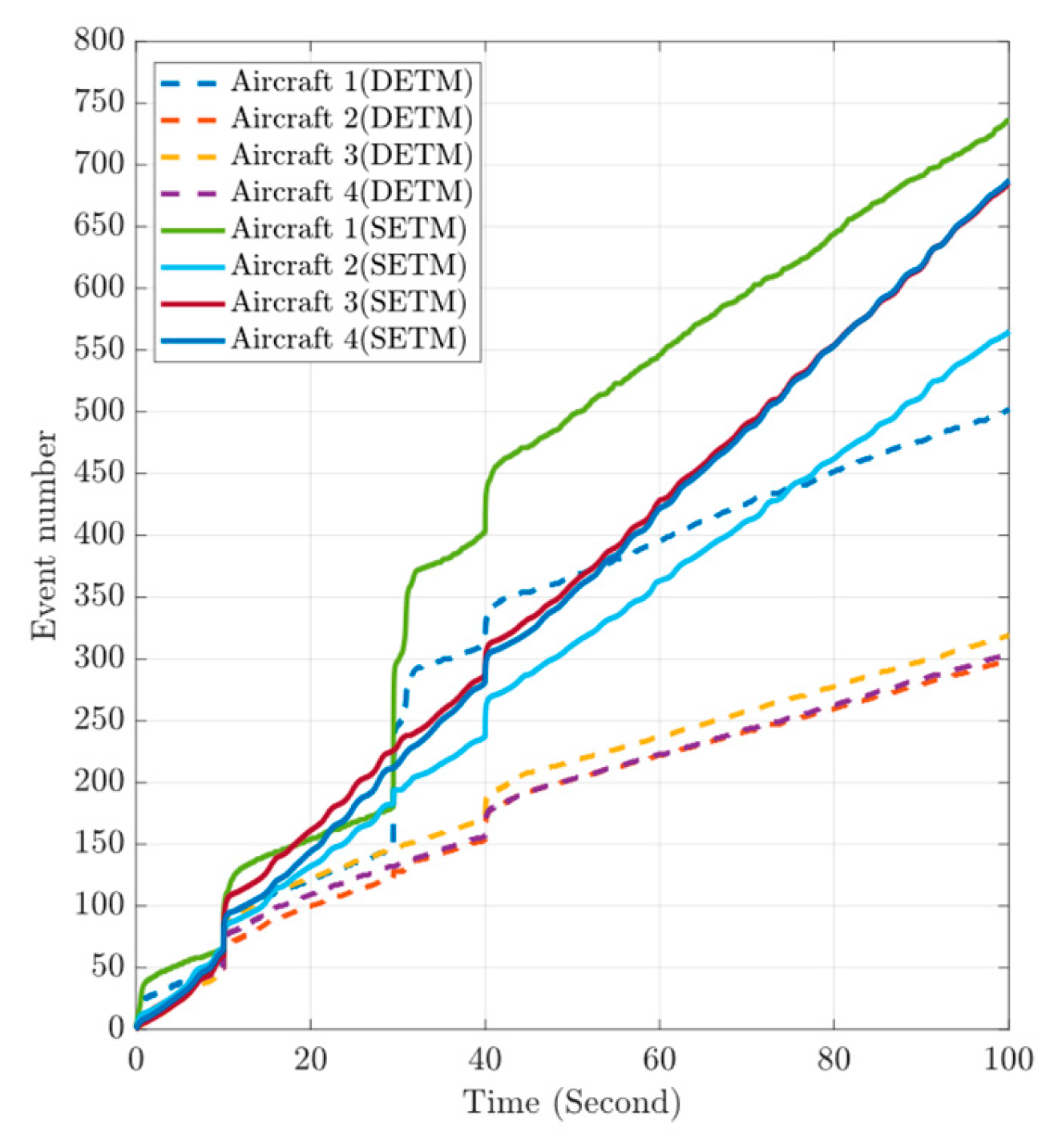
To verify the superiority of the designed dynamic event-triggered mechanism (DETM), by comparing it with the static event-triggered mechanism (SETM), an analysis is carried out from the aspects of the number of event triggers, trigger intervals, and the optimization effect of communication overhead. Figure 8 (comparison of the number of event triggers) and Table 3 show the curves of the number of event triggers of the four aircraft over time under DETM and SETM. Figure 9 presents the distribution of event trigger intervals of the 4 aircraft under DETM and SETM. It can be seen that
  • The growth rate of the number of event triggers for each aircraft (Aircraft 1–4) under DETM is significantly lower than that under SETM. Taking Aircraft 1 as an example, within the simulation period (100 s), the number of triggers of SETM reaches 700 times, while that of DETM is only about 500 times; other aircraft (such as Aircraft 2–4) also show similar patterns, and the number of triggers of DETM is obviously smaller;
  • In multi-stage tasks, such as formation trajectory tracking, formation transformation, and obstacle avoidance, the number of triggers of DETM is always lower than that of SETM. Especially in the dynamic stage of task switching (such as the 30–40 s obstacle-avoidance coordination period), the number of triggers of SETM rises sharply due to frequent communication requirements. However, DETM effectively suppresses the growth of the number of triggers by dynamically adjusting the trigger logic, verifying the adaptability of DETM to complex formation tasks;
  • The trigger intervals of DETM are larger than those of SETM, and the fluctuations are smoother. Taking Aircraft 1 as an example, the trigger intervals of SETM are mostly concentrated in the range of 0–600 ms, and short-interval triggers (<300 ms) occur frequently, while the trigger intervals of DETM are stably maintained at about 300 ms in the steady-state stage. Long-interval triggers (>600 ms) account for a higher proportion.
To verify the performance superiority of the finite-time state observer based on the fuzzy wavelet neural network (FTFWNBO) proposed in this paper, comparative simulations are carried out with the neural network state observer (FTNBO) in Reference [2]. Through the state observation errors  Γ x Γ v , as well as the external disturbances and the model uncertainties  Γ w , analyses are conducted from the dimensions of convergence characteristics, dynamic responses, and finite-time stability. The results are shown in Figure 10. The errors of both FTFWNBO and FTNBO decay with time, but the convergence rate of FTFWNBO is faster, and the steady-state error is smaller. This is attributed to the structural advantages of the fuzzy wavelet neural network in FTFWNBO, including the time-frequency locality of wavelet basis functions and the reasoning ability of fuzzy logic. This observer has stronger robustness to disturbances, and simultaneously achieves a faster error convergence rate and a smaller steady-state error, which is significantly superior to FTNBO.
Γ x = i = 1 N x ^ i x i 2 Γ v = i = i N v ^ i v i 2 Γ w = i = i N w ^ i w i 2
Through the analysis of the global error norm  p p d = i = i N p i p d , i 2  in Figure 11, for the obstacle-avoidance and tracking coordination ability, the controller realizes the coordination between dynamic trajectory re-planning and tracking control. When the obstacle-avoidance task is triggered, it can not only achieve effective obstacle avoidance but also quickly resume trajectory tracking, ensuring the compatibility of the obstacle-avoidance function and tracking performance. The coordination of high-precision trajectory tracking and strong robustness is achieved, verifying the engineering effectiveness and practicality of the proposed control method.
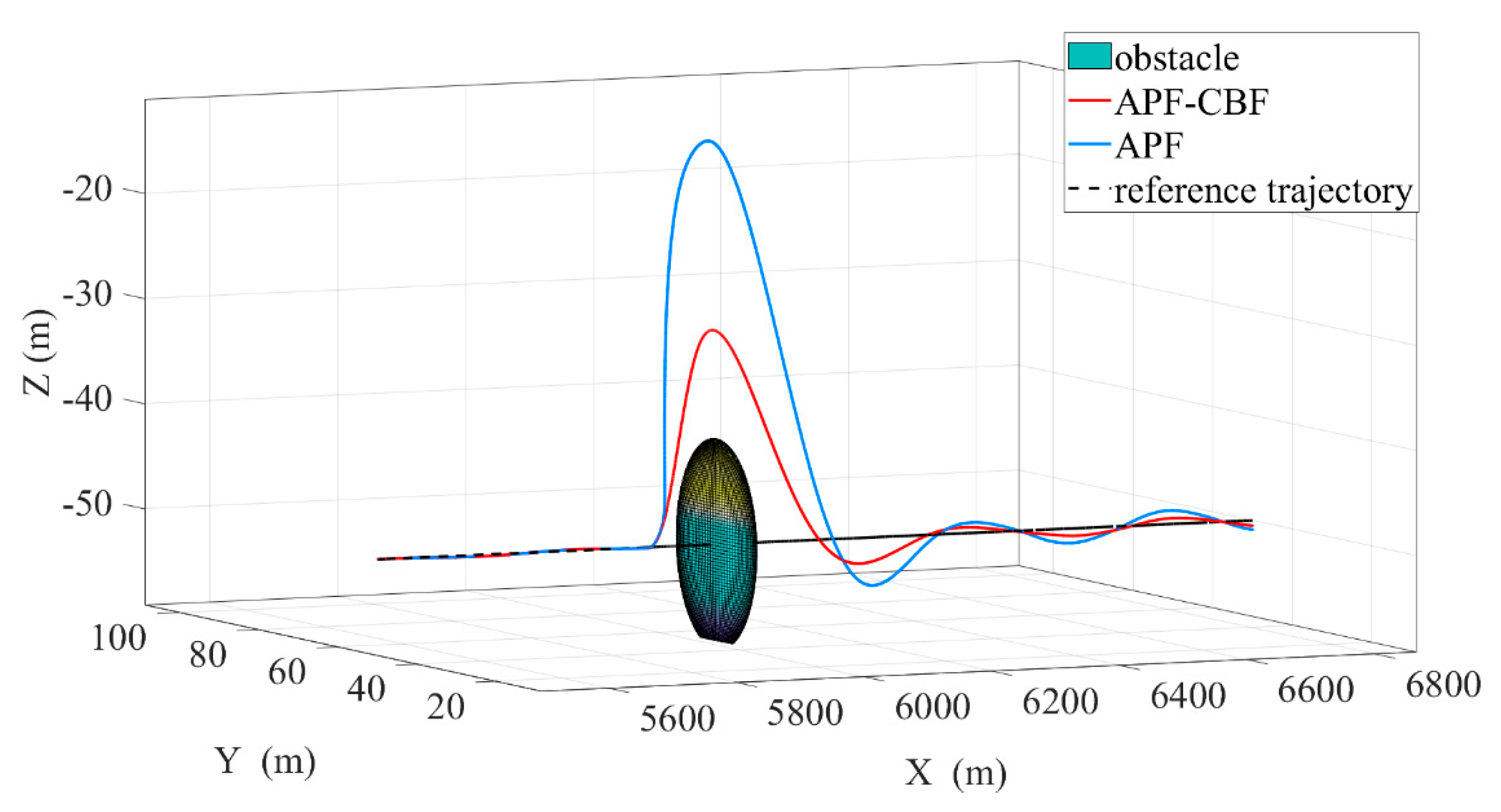
In this experiment, the differences in trajectory planning and obstacle-avoidance performance between the artificial potential field (APF) method proposed in Reference [1] and the artificial potential field method fused with control barrier function (APF-CBF) proposed in this paper are compared in an environment with obstacles, as shown in Figure 12. When the APF method approaches an obstacle, the trajectory shows an obvious tendency to cross over the obstacle. Theoretically, it can bypass the obstacle, but the trajectory has a large curvature near the obstacle, and the path is not smooth enough. Moreover, there is a potential risk of local oscillations of the trajectory due to the superposition of potential fields. In scenarios with complex multiple obstacles or high requirements for trajectory smoothness, it may cause frequent fluctuations of control commands, affecting the stability of the execution mechanism. The APF-CBF method utilizes the explicit handling of constraints by the control barrier function, and the trajectory realizes a more “compliant” obstacle-avoidance detour that conforms to the reference trajectory logic in the obstacle area. The path smoothness is significantly better than that of the APF method. Its trajectory morphology indicates that APF-CBF can effectively suppress unnecessary large-scale deviations of the trajectory while ensuring obstacle-avoidance safety, which is more in line with the requirements for trajectory quality in actual engineering.
Meanwhile, the reference-corrected collision avoidance algorithm based on APF-CBF proposed in this paper is compared with the artificial potential field collision avoidance algorithm proposed in [2]. As can be seen from Figure 13, compared with the APF method, the APF-CBF method proposed in this paper can make the trajectory of the aircraft complete the mutual collision avoidance among multiple aircraft more smoothly. In terms of trajectory smoothness and the degree of fitting to the expected path, APF-CBF shows significant advantages. It can make the aircraft smoother in the collision avoidance process and ensure that the trajectory does not deviate excessively from the reference trajectory, which is very beneficial to maintaining the stability of the aircraft’s motion. On the contrary, the trajectory generated by the APF method has a large deviation from the reference trajectory, especially in the collision avoidance area. This indicates that the traditional APF method is prone to causing trajectory deformation when performing collision avoidance tasks, which may affect the accuracy of subsequent operations or the stability of the formation. This difference originates from the different characteristics of the two algorithms. The reference-corrected method based on APF-CBF proposed in this paper, on the basis of the real-time performance of APF, can not only ensure real-time performance but also achieve the smoothness of the flight trajectory and energy saving through the control barrier function and quadratic programming algorithm.
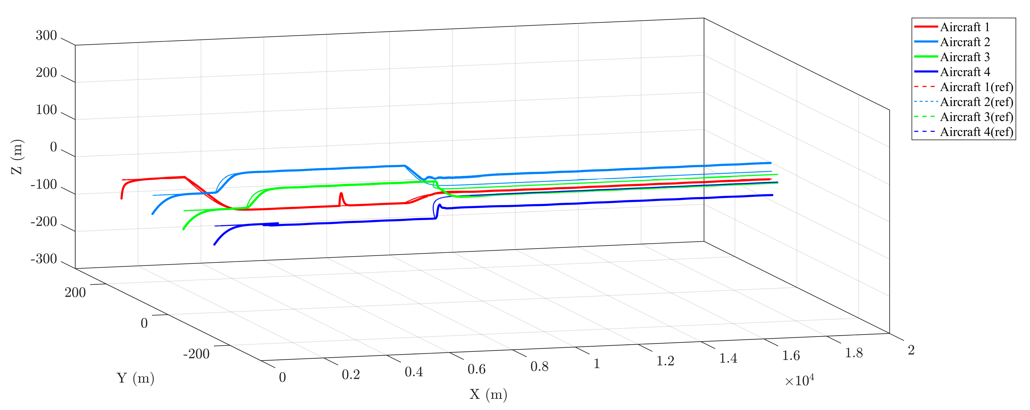
For the global trajectory planning and tracking tasks of the formation of multiple aircraft (Aircraft 1–4), by comparing the actual flight trajectories with the reference trajectories, as shown in Figure 14. In the three-axis directions of X, Y, and Z, the actual trajectories all fluctuate slightly around the reference trajectories. This verifies the high-precision tracking capability of the designed trajectory tracking controller, which can drive multiple aircraft to stably fit the preset reference trajectories in three-dimensional space, meeting the basic requirement for trajectory consistency in formation flight. Meanwhile, when encountering obstacles and adjacent aircraft, the trajectories are automatically adjusted to avoid collisions, and after adjustment, the formation configuration is quickly restored. There is no situation of trajectory crossing or deviation from the formation layout. This fully indicates that the trajectory planning and tracking algorithm can complete the collision-avoidance task while ensuring the coordination of the multiple-aircraft formation.

5. Conclusions

This study focuses on the cooperative collision avoidance problem of multiple aircraft in complex dynamic environments. A trajectory correction algorithm based on APF-CBF is proposed, which effectively overcomes the defects existing in traditional methods, such as the inability to reduce energy consumption during obstacle avoidance and the requirement of pre-knowing the global reference trajectory. Aiming at the problem that multiple aircraft need to save communication resources and computing resources in the process of cooperative collision avoidance and tracking, the designed dynamic event-triggered algorithm can significantly reduce the number of communications in the multi-aircraft formation compared with the traditional mode. The finite-time fuzzy wavelet state observer breaks through limitations and effectively improves observation efficiency, providing a high-precision guarantee for trajectory tracking and collision avoidance control. However, this study still has certain limitations: the online self-adjustment strategy of the trigger threshold of the event-triggered mechanism needs to be further refined; when the current reference correction strategy deals with dense dynamic obstacle clusters, it shows insufficient capability in global trajectory planning, leading to a decrease in the overall task efficiency of the formation. In the future, research can be extended to the scenario of heterogeneous aircraft formations, and optimization algorithms can be introduced to enhance the formation’s ability to reduce energy consumption while achieving real-time collision avoidance. Overall, this study provides an innovative solution for the field of cooperative collision avoidance of multiple aircraft, and is expected to promote the wide application and development of related technologies in practical engineering.

Author Contributions

Conceptualization, Y.T. and J.L.; methodology, Y.T. and X.B.; software, C.L. and J.Y.; validation, Y.T. and C.L.; formal analysis, Y.T.; investigation, Y.T.; resources, C.L.; data curation, Y.T.; writing—original draft preparation, C.L.; writing—review and editing, Y.T.; visualization, C.L.; supervision, Y.T.; project administration, J.Y.; funding acquisition. All authors have read and agreed to the published version of the manuscript.

Funding

The funding for this research comes from J.Y.

Data Availability Statement

The data presented in this study are available on request from the corresponding author. The data are not publicly available due to privacy concerns.

Conflicts of Interest

The authors declare no conflicts of interest.

References

  1. Fei, Y.; Shi, P.; Lim, C.C. Robust Formation Control for Multi-Agent Systems: A Reference Correction Based Approach. IEEE Trans. Circuits Syst. I Regul. Pap. 2021, 68, 2616–2625. [Google Scholar] [CrossRef]
  2. Fei, Y.; Shi, P.; Lim, C.C. Robust and Collision-Free Formation Control of Multiagent Systems With Limited Information. IEEE Trans. Neural Netw. Learn. Syst. 2023, 34, 4286–4295. [Google Scholar] [CrossRef] [PubMed]
  3. Pan, Z.; Zhang, C.; Xia, Y.; Xiong, H.; Shao, X. An Improved Artificial Potential Field Method for Path Planning and Formation Control of the Multi-UAV Systems. IEEE Trans. Circuits Syst. II Express Briefs 2022, 69, 1129–1133. [Google Scholar] [CrossRef]
  4. Yang, Y.; Liu, Q.; Tan, H.; Shen, Z.; Wu, D. Collision-Free and Connectivity-Preserving Formation Control of Nonlinear Multi-Agent Systems With External Disturbances. IEEE Trans. Veh. Technol. 2023, 72, 9956–9968. [Google Scholar] [CrossRef]
  5. Shao, M.; Liu, X.; Xiao, C.; Zhang, T.; Yuan, H. Research on UAV Trajectory Planning Algorithm Based on Adaptive Potential Field. Drones 2025, 9, 79. [Google Scholar] [CrossRef]
  6. Antony, A.; Kumar, S.R.; Mukherjee, D. Artificial Potential Fields based Formation Control for Fixed Wing UAVs with Obstacle Avoidance. IFAC-PapersOnLine 2024, 57, 19–24. [Google Scholar] [CrossRef]
  7. Qian, M.; Wu, Z.; Jiang, B. Cerebellar Model Articulation Neural Network-Based Distributed Fault Tolerant Tracking Control With Obstacle Avoidance for Fixed-Wing UAVs. IEEE Trans. Aerosp. Electron. Syst. 2023, 59, 6841–6852. [Google Scholar] [CrossRef]
  8. Chen, Y.; Singletary, A.; Ames, A.D. Guaranteed Obstacle Avoidance for Multi-Robot Operations With Limited Actuation: A Control Barrier Function Approach. IEEE Control. Syst. Lett. 2021, 5, 127–132. [Google Scholar] [CrossRef]
  9. Li, J.; Kang, H.; Li, J.; Song, S. Bearing-Based Collision-Free Formation Control for Spacecrafts Under Dynamic Event-Triggered Input. IEEE Trans. Autom. Sci. Eng. 2025, 22, 14855–14866. [Google Scholar] [CrossRef]
  10. Wu, S.; Fang, Y.; Sun, N.; Lu, B.; Liang, X.; Zhao, Y. Optimization-Free Smooth Control Barrier Function for Polygonal Collision Avoidance. IEEE Trans. Cybern. 2025, 55, 4257–4269. [Google Scholar] [CrossRef]
  11. Tian, X.; Lin, J.; Liu, H.; Huang, X. Event-Triggered Finite-Time Formation Control of Underactuated Multiple ASVs with Prescribed Performance and Collision Avoidance. Sensors 2023, 23, 6756. [Google Scholar] [CrossRef] [PubMed]
  12. da Vangasse, C.; Freitas, J.R.; Raffo, V.; Pimenta, C.A. Safe Navigation on Path-Following Tasks: A Study of MPC-based Collision Avoidance Schemes in Distributed Robot Systems. J. Intell. Robot. Syst. 2024, 110, 166. [Google Scholar] [CrossRef]
  13. Molnar, T.G.; Kannan, S.K.; Cunningham, J.; Dunlap, K.; Hobbs, K.L.; Ames, A.D. Collision Avoidance and Geofencing for Fixed-Wing Aircraft With Control Barrier Functions. IEEE Trans. Control. Syst. Technol. 2025, 33, 1493–1508. [Google Scholar] [CrossRef]
  14. Chen, H.; Huang, D.; Wang, C.; Ding, L.; Song, L.; Liu, H. Collision-Free Path Planning for Multiple Drones Based on Safe Reinforcement Learning. Drones 2024, 8, 481. [Google Scholar] [CrossRef]
  15. Németh, B.; Lelkó, A.; Antal, Z.; Csaba, A. Collision-free trajectory design for dance choreography of virtual drones in hierarchical structure. IFAC-PapersOnLine 2022, 55, 502–507. [Google Scholar] [CrossRef]
  16. Liao, B.H.; Lee, C.Y.; Wang, L.C. Aerodynamics-Based Collision-Free Control of Connected Drones in Complex Urban Low-Altitude Airspace Using Distributional Reinforcement Learning. IEEE Trans. Veh. Technol. 2024, 73, 9763–9775. [Google Scholar] [CrossRef]
  17. Seah, S.X.; Srigrarom, S. Multiple UAS Traffic Planning Based on Deep Q-Network with Hindsight Experience Replay and Economic Considerations. Aerospace 2023, 10, 980. [Google Scholar] [CrossRef]
  18. Peng, C.; Liu, X.; Ma, J. Design of Safe Optimal Guidance With Obstacle Avoidance Using Control Barrier Function-Based Actor–Critic Reinforcement Learning. IEEE Trans. Syst. Man Cybern. Syst. 2023, 53, 6861–6873. [Google Scholar] [CrossRef]
  19. Bulka, E.; Nahon, M. High-Speed Obstacle-Avoidance with Agile Fixed-Wing Aircraft. In Proceedings of the 2019 International Conference on Unmanned Aircraft Systems (ICUAS), Atlanta, GA, USA, 11–14 June 2019; IEEE: Piscataway, NJ, USA, 2019; pp. 971–980. [Google Scholar]
  20. d’Apolito, F. Reinforcement Learning Training Environment for Fixed Wing UAV Collision Avoidance. IFAC-PapersOnLine 2022, 55, 281–285. [Google Scholar] [CrossRef]
  21. Campos-Martínez, S.-N.; Hernández-González, O.; Guerrero-Sánchez, M.-E.; Valencia-Palomo, G.; Targui, B.; López-Estrada, F.-R. Consensus Tracking Control of Multiple Unmanned Aerial Vehicles Subject to Distinct Unknown Delays. Machines 2024, 12, 337. [Google Scholar] [CrossRef]
  22. Bu, X.; Luo, R.; Lei, H. Fuzzy-Neural Intelligent Control With Fixed-Time Pre-Configured Qualities for Electromechanical Dynamics of Electric Vehicles Motors. IEEE Trans. Intell. Transp. Syst. 2025, 26, 1193–1202. [Google Scholar] [CrossRef]
  23. Wang, L.; Li, A.; Xiao, C.; Wang, C.; Zabolotnov, Y. Distributed adaptive disturbance observer-based multi-channel event-triggered finite-time coordinated control for multi-UAVs with actuator failures. Aerosp. Sci. Technol. 2024, 151, 109319. [Google Scholar] [CrossRef]
  24. Li, J.; Tang, Y.; Shao, L.; Bu, X.; Ye, J. Finite-Time RBFNN-Based Observer for Cooperative Multi-Missile Tracking Control Under Dynamic Event-Triggered Mechanism. Aerospace 2025, 12, 693. [Google Scholar] [CrossRef]
  25. Lewis, F.L.; Zhang, H.; Hengster-Movric, K.; Das, A. Cooperative Control of Multi-Agent Systems: Optimal and Adaptive Design Approaches; Springer Science Business Media: Berlin/Heidelberg, Germany, 2013. [Google Scholar]
  26. Bu, X.; Jiang, B.; Lei, H. Low-Complexity Fuzzy Neural Control of Constrained Waverider Vehicles via Fragility-Free Prescribed Performance Approach. IEEE Trans. Fuzzy Syst. 2023, 31, 2127–2139. [Google Scholar] [CrossRef]
  27. Bu, X.; Jiang, B.; Lei, H. Nonfragile Quantitative Prescribed Performance Control of Waverider Vehicles with Actuator Saturation. IEEE Trans. Aerosp. Electron. Syst. 2022, 58, 3538–3548. [Google Scholar] [CrossRef]
  28. Shao, X.; Si, H.; Zhang, W. Fuzzy wavelet neural control with improved prescribed performance for MEMS gyroscope subject to input quantization. Fuzzy Sets Syst. 2021, 411, 136–154. [Google Scholar] [CrossRef]
  29. Isaly, A.; Ghanbarpour, M.; Sanfelice, R.G.; Dixon, W.E. On the Feasibility and Continuity of Feedback Controllers Defined by Multiple Control Barrier Functions. IEEE Trans. Autom. Control. 2024, 69, 7326–7339. [Google Scholar] [CrossRef]
  30. Xu, Y.; Liu, L.; Yin, Y.; Wang, D.; Peng, Z. Multi-ASV Motion Planning for Formation Reconfiguration based on Control Barrier Functions. IFAC-PapersOnLine 2022, 55, 223–227. [Google Scholar] [CrossRef]
  31. Wang, H.; Liu, Q.; Xu, C. Predefined-time distributed optimization and anti-disturbance control for nonlinear multi-agent system with neural network estimator: A hierarchical framework. Neural Netw. 2024, 175, 106270. [Google Scholar] [CrossRef]
  32. Fei, Y.; Wang, L.; Qu, X. Event triggered cooperative trajectory coordination for platooning among heterogeneous vehicles. Transp. Res. Part C Emerg. Technol. 2025, 173, 105049. [Google Scholar] [CrossRef]
  33. Hao, R.; Zhou, W.; Wang, Y.; Yan, Y. Event-Triggered Impulsive Formation Control for Cooperative Obstacle Avoidance of UAV Swarms in Tunnel Environments. Drones 2025, 9, 421. [Google Scholar] [CrossRef]
  34. Yan, Y.; Liu, S.; Hao, R. RRT*-APF Path Planning and MA-AADRC-SMC Control for Cooperative 3-D Obstacle Avoidance in Multi-UAV Formations. Drones 2025, 9, 611. [Google Scholar] [CrossRef]
  35. Wang, K.; Lu, J.; Zhou, H. Employing Fuzzy Adaptive and Event-Triggered Approaches to Achieve Formation Control of Nonholonomic Mobile Robots Under Complete State Constraints. Appl. Sci. 2025, 15, 2827. [Google Scholar] [CrossRef]
  36. Chen, W.; Hu, Y.; Gao, C.; An, R. Trajectory tracking guidance of interceptor via prescribed performance integral sliding mode with neural network disturbance observer. Def. Technol. 2024, 32, 412–429. [Google Scholar] [CrossRef]
Figure 1. Model of fixed-wing aircraft.
Aerospace 12 00803 g001
Figure 2. Geometric Relationship Among Various Objects.
Aerospace 12 00803 g002
Figure 3. Control Framework.
Aerospace 12 00803 g003
Figure 4. Communication Topology.
Aerospace 12 00803 g004
Figure 5. The Position Tracking Error Diagram.
Aerospace 12 00803 g005
Figure 6. The Velocity Tracking Error Diagram.
Aerospace 12 00803 g006
Figure 7. The Control Output Diagram.
Aerospace 12 00803 g007
Figure 8. Comparison of Trigger Counts.
Aerospace 12 00803 g008
Figure 9. Comparison of Event Numbers.
Aerospace 12 00803 g009
Figure 10. Observation Performances of FTFWNBO and FTNBO.
Aerospace 12 00803 g010
Figure 11. Norm of Tracking Error.
Aerospace 12 00803 g011
Figure 12. Comparison between APF and APF-CBF in Obstacle Avoidance.
Aerospace 12 00803 g012
Figure 13. Comparison between the APF and APF-CBF in Collision Avoidance.
Aerospace 12 00803 g013
Figure 14. Global Trajectory.
Aerospace 12 00803 g014
Table 1. Initial State Information of Multi-Aircraft Formation.
Aircraft Numberx-Direction Position (m)y-Direction Position (m)z-Direction Position (m)Velocity (m)Flight Path Angles (rad)Flight Path Angles (rad)
10150−502000.010.01
2050−502000.010.01
30−50−502000.010.01
40−150−502000.010.01
Table 2. The parameters in the observer, controller, and triggering conditions.
ParametersValue
α 1 a 2 β 1 β 2 0.2 0.2 0.5 0.5
r ¯ i , k r _ i , k r ¯ i , j r _ i , j 3 5 3 5
Λ d i a g ( 0.5 , 0.5 , 0.5 )
k i c i 0.5 0.2
l χ 0.2 0.8
ν J i 2 0.2
Table 3. Comparison of Trigger Counts and Reduction Percentages.
Formation MemberAircraft 1Aircraft 2Aircraft 3Aircraft 4
Without ETM1000100010001000
SETM738562683681
DETM502298321302
Percentage reduction49.8%70.2%67.9%69.8%
Disclaimer/Publisher’s Note: The statements, opinions and data contained in all publications are solely those of the individual author(s) and contributor(s) and not of MDPI and/or the editor(s). MDPI and/or the editor(s) disclaim responsibility for any injury to people or property resulting from any ideas, methods, instructions or products referred to in the content.