Abstract
Unmanned aerial manipulators (UAMs), composed of unmanned aerial vehicles (UAVs) and manipulators, have great application potential in aerial manipulation like precision inspection, disaster rescue, etc. However, strong dynamic coupling exists between UAVs and manipulators. In addition, UAMs meet external disturbances such as gusts of wind during movements. Also, the control performance metrics, such as tracking accuracy and control stability, are seriously affected. Therefore, a cooperative control method is developed for a UAM system with a UAV and a 2-degree-of-freedom manipulator. First, the Euler–Lagrange formulation is employed to study the UAM dynamics like inertial forces and coupling effects. Then, an integral sliding mode control (ISMC) method with an integral term is developed to enhance robustness and eliminate steady-state errors. Finally, the proposed ISMC method is validated through numerical simulations in Matlab R2024a, introducing comparative analyses with the Proportional–Integral–Derivative (PID) and SMC controllers. The simulation results and the comparative analyses validate the effectiveness of ISMC, showing its superiority over the PID and SMC controllers in handling dynamic coupling and external disturbances, where the overshoot of ISMC is reduced by an average of more than 90%. The ISMC method provides a high-performance control strategy to promote the practical application of UAMs in various aerial manipulation tasks and lays the foundation for further optimizing control methods for more complex UAM systems.
1. Introduction
Unmanned aerial vehicles (UAVs) [1,2] have been deeply integrated into numerous fields due to their small size, simple structure, and high maneuverability, among others. However, most UAVs [3,4] are mainly limited to monitoring, mapping, sensing, and other non-interactive aspects. The UAM (unmanned aerial manipulator) [5,6,7], composed of a UAV and a manipulator, can be used to perform fine and complex aerial operation tasks. In dangerous forests and maritime and radiation-affected environments, UAMs [8,9,10] can perform environmental monitoring, marine garbage fishing, and detection tasks, saving a lot of human and material resources. In high-altitude areas, UAMs can carry the necessary items to overhaul aerial electrical lines, providing guarantees for the stable supply of power and communication. Within harsh environments like floods, droughts, and high-altitude fires, UAMs can directly participate in aerial rescue, e.g., by carrying supply materials to difficult-to-reach places. With the advantage of transforming passive tasks into active ones, UAMs [11,12,13] have been gradually employed in various fields, which in turn increases their application value. Compared with a UAV, a UAM has the following particularities: First, the degrees of freedom (DOFs) in a UAM are increased, while the geometric structure of a UAM is not symmetric. As a result, the UAM kinematics and dynamics become more complicated, leading to significant challenges in the derivation of UAM models. Second, the base of a ground-based manipulator is usually fixed, while the base of a UAM system is in free-flying mode, which involves considering the six DOFs of the UAV in addition to those of the manipulator. Third, strong coupling arises between the UAV and the manipulator. Therefore, it is a significant challenge to model the UAM system and develop cooperative control from this model.
Several works have studied UAMs in recent years. For example, in [14], a quadrotor UAV is equipped with a rigid device with four hooks, where the hooks are installed at the bottom of the UAV and employed for grasping objects. In [15], the helicopter is equipped with a passive compliant gripper with one DOF. In [16], a lateral manipulator is installed at the bottom of a single-rotor helicopter, enabling it to grasp lightweight tubular objects in the direction of the helicopter’s movement. In [17], the developed quadrotor UAV is equipped with a simple gripper, which could clean up objects in dangerous areas. Due to the limited flexibility and operational capability of grippers, UAVs with multi-DOF-based robotic arms have also attracted the attention of the research community [18]. For example, in [19], the German Aerospace Center (DLR) developed a UAM system, where an industrial robotic arm with seven DOFs is installed at the bottom of a single-rotor helicopter, which could grasp upright long poles on the ground. In turn, in [20], a quadrotor UAV is equipped with three manipulators, with each manipulator having two DOFs. The UAM system is capable of pushing and pulling target objects. In [21], a manipulator with six DOFs is installed on the side of a quadrotor UAV, where the end effector of the attached manipulator can maintain stable contact with vertical objects. In [22], a lightweight pendulum with a single DOF is installed at the top center of a quadrotor UAV, where the swing direction is consistent with the pitch direction of the UAV. This system could achieve stable contact between the yaw pendulum and vertical walls. In [23], a manipulator with three DOFs is mounted at the bottom of a UAV for assembly tasks.
The dynamic model and the stable control of UAM are crucial for performing practical aerial tasks. There are two main approaches for modeling a UAM system, including the integrated modeling method [24,25] and the separated modeling method [26,27]. For the integrated modeling method, the UAM is set as a multi-rigid-body system. The dynamic coupling between the UAV and the manipulator is considered an internal factor. For the separated modeling method, the UAM system is divided into two independent systems. The coupling effect of the manipulator on the UAV is treated as an external disturbance to the UAV system. According to the UAM modeling method, the control methods for UAMs can be divided into two categories, namely centralized control and decentralized control.
Caccavale [28] proposed a method combining gain scheduling with Lyapunov-based model reference adaptive control to achieve the dynamic stability control of a UAM. This method enables precise simulation and control of the UAV when the manipulator interacts with target objects. Ruggiero [29] developed a motion tracking control method for UAMs, where top-level control and the bottom-level control are combined. The inverse kinematics of UAM were used to calculate each channel variable, while the forward kinematics were utilized to track the UAM’s motion.
The most commonly used control methods for UAMs include the Linear–Quadratic Regulator (LQR), backstepping control, feedback linearization, adaptive control, and Model Predictive Control (MPC), among others. During the designing of an LQR controller, it is necessary to linearize the UAM system at the equilibrium point [30], which results in a local stabilization method. Therefore, the stability of the system cannot be guaranteed in the case that the system state deviates far from the equilibrium point. The backstepping control method is usually employed for systems with a cascade structure, such as UAMs, which are underactuated systems and have a cascade structure [31]. In [31], a backstepping control algorithm is developed, where the UAM dynamics are decoupled into the translational dynamics of the UAV base and the dynamics of the manipulator. In [32], the feedback linearization technique is applied to linearize the dynamic model accounting for the angular velocities of an unmanned helicopter and the joint angular velocities of the manipulator. The adaptive control approach is known to estimate uncertain parameters of UAM models and disturbances while the UAM performs its tasks. When the UAM is performing tasks with an unknown load mass, the control performance could be easily affected. To address this issue, an adaptive controller is designed in [33]. The mass of the carried load is estimated, and a good trajectory tracking performance is obtained. When the UAM performs target picking tasks, it experiments with model uncertainties such as load variation, external disturbances during contact, and so on. To improve the system robustness against uncertain parameters in the model and external disturbances, an impedance control method is developed for the precise tracking of the end effector trajectory. The UAM’s stability is guaranteed even when it is in contact with its environment. In [34], a nonlinear MPC (NMPC) method is developed to achieve optimal system performance during trajectory tracking of the end effector position. To perform grasping tasks for UAMs, an MPC-based method is developed to control the end effector position. The UAV position trajectories and manipulator joints are computed utilizing MPC, which are then tracked by employing a PID controller. The system’s stability is guaranteed during large-range movement and grasping operations of the UAM manipulator.
The sliding mode control (SMC) method [35,36,37,38,39] has been widely employed for UAMs due to its strong robustness and fast convergence characteristics. In [35], a fuzzy sliding mode controller, combined with an extended state observer, is developed for the attitude control of rotary-wing flying manipulators. The UAV disturbance, caused by manipulator movement, is effectively suppressed. In addition, the system’s stability is guaranteed. Li [36] studied the nonlinear characteristic modeling method and developed a discrete-time sliding mode controller. Furthermore, the anti-coupling disturbance performance is verified in real flight experiments. Chen [37] introduces an adaptive sliding mode disturbance observer. The finite-time convergence and the preset performance constraints are realized under unknown disturbances with upper bounds. D’Angelo [38] develops a semi-autonomous operation mode utilizing the parallel force/visual control method, balancing the flexibility of human operation and the efficiency of autonomous control in industrial inspection tasks. Yu [39] combines the mechanical-priors-based neural network modeling method with an improved terminal sliding mode reaching law to enhance the trajectory tracking speed and the robustness of the manipulator under the constraint of the base vibration. Kumar [40] combines the neural network compensation with a nonlinear sliding mode surface for pipeline maintenance utilizing manipulators. The tracking accuracy is improved under certain disturbance conditions. A fractional-order sliding mode control method is proposed in [41] based on a fractional-order disturbance observer for free-floating space manipulators. The transient response and the tracking accuracy are effectively improved.
The aforementioned studies focus on improving the robustness of UAV controllers to ensure the flight stability of UAM systems during manipulation operations. In the case that the manipulator experiments large forces/torque disturbances, a stable flight of the UAV cannot be guaranteed. A PID control method can be developed for UAVs, which could meet the requirements when performing simple object grasping tasks. However, the position control error of UAV increases when the manipulator moves, leading to a significant variation in the UAM center of mass. In order to solve the above problems, an ISMC-based anti-disturbance control method is developed for the cooperative control of a UAM system. The dynamic model is established utilizing the Euler–Lagrange theory. An anti-disturbance control law is designed to solve the problems of strong dynamic coupling and external disturbances. The system’s stability is guaranteed. Additionally, the respond speed is fast, the overshoot is small, and the steady-state error is close to zero. Therefore, the engineering application potential is highlighted in complex aerial tasks.
The remainder of this manuscript is structured as follows: Section 2 studies the dynamics of UAMs and depicts the problem statement. In Section 3, the ISMC method is developed. The simulation results and comparisons between the proposed controller and a classical PID are provided in Section 4 to validate the ISMC approach. Finally, in Section 5, some conclusions are given.
2. UAM Dynamics
Figure 1 shows the geometric structure of a UAM system, consisting of an X-type UAV and a two-DOF manipulator. The manipulator is installed at the bottom of the UAV. As shown in Figure 1, three coordinate systems are depicted, including the earth coordinate system , the UAV coordinate system , and the end effector coordinate system . The origin of is denoted as referring to the earth coordinate system and is written as in the UAM coordinate system. In turn, the UAV attitude is depicted as .
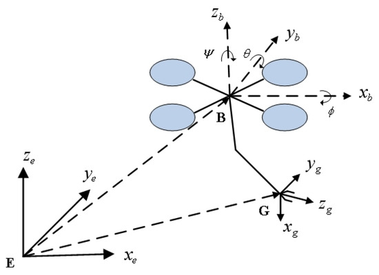
Figure 1.
Kinematic structure and coordinate frames of the UAM.
The manipulator coordinate system is installed at the end effector. The coordinates of the end effector position are denoted as . In turn, the end effector attitude is denoted as .
In the case that a target moves out of the plane, the UAV first performs a yaw motion so that the UAV is pointing towards the target. Figure 2 shows the 2D geometric structure of the developed UAM in the plane, in which and denote the length of the two links of the manipulator, and denote the joint angles of the manipulator, denotes the pitch angle of the UAV, c is the distance from the center of link 1 to the connection point of the UAV and the manipulator, and b is the distance from the center of link 2 to the second joint.
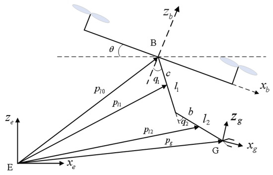
Figure 2.
Representation of the UAM in the plane.
In the earth coordinate system , the center of masses for the UAV, link 1, and link 2 can be formulated as follows:
By taking the time derivative of (1)–(3), the velocities of the UAV, link 1, and link 2 are computed as follows:
where , , and are the components of the linear velocity of the UAV, is the pitch angular velocity of the UAV, and and are the angular velocities of links 1 and 2, respectively. Since the manipulator is hinged below the UAV, the time derivatives of the Euler angles of the UAV and the manipulator joints are computed as follows:
where and are, respectively, the angular velocities of link 1 and link 2 in the frame. According to the Euler–Lagrange formulation, the kinetic energy of the UAM components is derived as follows:
where , , and are the kinetic energy of the UAV, link 1, and link 2, respectively, , , and are the principal moments of inertia of the UAV, and and are the moments of inertia of link 1 and link 2, respectively. The kinetic energy of the UAM system is simply given by the following:
In turn, the potential energy of UAM system is computed as follows:
By computing the Lagrangian and applying the Euler–Lagrange equations, one can obtain the Lagrangian model of the UAM:
where is the state vector, denotes the inertia matrix, denotes the vector composed of centrifugal and Coriolis forces, denotes the gravity forces vector, and are the inputs of the system. Furthermore, the aforementioned quantities can be explicitly computed as follows.
Along the x-axis:
Along the y-axis:
Along the z-axis:
Along the roll angle :
Along the pitch angle :
Along the yaw angle :
Along :
Along :
The second time derivatives, needed to build the state space model, can be obtained by inverting (12), as follows:
which is always possible since is a symmetric positive definite matrix.
3. ISMC-Based Cooperative Control Method
In recent years, the sliding mode control (SMC) method has been widely employed in the field of nonlinear control due to its simplicity and effectiveness. It is suitable for high-precision system control scenarios and has been successfully employed for manipulators, aircraft, motors, etc. The SMC has the advantages of fast response speed, few parameters to adjust, and strong robustness. Because of the dynamic behavior of both the actuators and the UAM mechanics, the employment of SMC presents the well-known chattering phenomenon. The quasi-sliding mode method is mainly used to solve this problem, where the sign function is replaced by a saturation function. As the thickness of the boundary layer increases, the chattering is mitigated. However, the control performance is deteriorated.
In this section, an integral sliding mode control (ISMC) method is developed. Here, we propose a state integral term on the conventional sliding surface so that the control system lies within the sliding mode region at the initial reaching phase. The system state can quickly converge to the preset trajectory within a finite time period, thereby reducing tracking errors, accelerating system convergence, mitigating chattering, and meeting the corresponding performance specifications.
The tracking error is defined as follows:
where e denotes the error vector and and denote the desired value and the actual value, respectively. The traditional sliding mode surface is usually selected as a one-dimensional matrix, the absolute value of which is calculated during utilization. In this paper, the sliding mode surface is selected as a multi-dimensional matrix as follows, which is actually a six-dimensional matrix.
where and are coefficient matrices with positive values. The values of and are selected based on a combination of theoretical stability requirements and empirical tuning through simulation trials. In order to satisfy the following Lyapunov stability conditions and ensure the convergence of the sliding surface, and are initially assigned to and , respectively. Then, and are fine-tuned via multiple simulation experiments to achieve a good balance between tracking performance, response speed, and chattering suppression. The values of and are selected by trial and error, in order to provide the best overall performance in both cases with disturbances and without disturbances.
The sign function of the sliding mode has the characteristics of hysteresis during the control switching process in practice, leading to the chattering problem. In order to solve the problem, the boundary layer method is developed to weaken the chattering in the integral sliding mode system. The related function set is established as follows, contributing to solving the aforementioned problem.
where denotes the thickness of the boundary layer, which is assigned as 0.4. The derivative of s is formulated as follows:
where W and Q are coefficient matrices with positive values.
The Lyapunov stability theory is employed to analyze the closed loop stability, where the Lyapunov function V is selected as follows:
The derivative of V is computed as follows:
According to (43) and (44), the Lyapunov function is positive definite when , with only for , and its derivative is negative definite. Therefore, the system is asymptotically stable at the equilibrium point. Moreover, the system will eventually converge to the sliding mode surface, satisfying the Lyapunov stability criterion.
Figure 3 shows the ISMC diagram for UAM. The ISMC system consists of a sliding surface structure, a UAV position controller, a UAV attitude controller, a manipulator controller, an allocation controller, and the UAM system. The signal generator provides the desired values, including the UAV position, UAV yaw angle, and the manipulator joint angles. The sliding surface structure calculates the sliding mode surfaces for each control channel using the state errors. The UAV position controller processes the desired position commands to determine the required total thrust and derive the desired pitch and roll angles for the attitude controller. The attitude controller receives the derived pitch and roll angle commands and calculates the corresponding pitch and roll moments. The manipulator controller computes the joint torques on the basis of desired joint angles. The allocation controller integrates all control inputs and provides the actual control signals for the UAV. Finally, the actual UAM states are fed back to the controllers to form a closed-loop control system, ensuring stability and tracking performance.
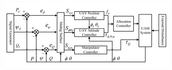
Figure 3.
ISMC diagram for the UAM.
Figure 4 presents the flow diagram of the ISMC. The steps of the ISMC are as follows: (1) initialization of the desired signal inputs; (2) construction of error and integral sliding surface; (3) construction of exponential reaching law; (4) control law synthesis with model terms; (5) UAM dynamics and feedback; and (6) action of external disturbances.
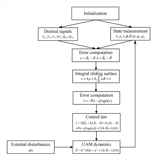
Figure 4.
Flow diagram of the ISMC.
4. Numerical Simulations
Numerical simulations are carried out to verify the proposed ISMC method. Two cases are studied, namely the case without disturbances and the case when disturbances are present. For each case, comparisons are provided between the ISMC and the PID controllers. As stated before, the UAM system consists of an X-type UAV and a two-DOF manipulator. The values of the UAM physical parameters are shown in Table 1.

Table 1.
Physical parameters of UAM.
4.1. Case 1: Without Disturbances
In this case, the hovering capability of the UAM is verified during manipulator movements under ideal conditions. First, the UAM system is set to move 1 m along the z-axis and the value of the desired yaw angle is set to at the initial moment, i.e., when s. Second, the UAM system is required to move 1 m along the y-axis at s. Third, the UAM system is required to move 1 m along the x-axis at s. Fourth, the first link is constrained to rotate an angle of at s. Finally, the second link is constrained to rotate at s. During simulations, the ODE45 solver is utilized with a variable step size. The tuning parameters for the ISMC are set, , , , , and , where denotes the identity matrix of adequate dimensions. The parameters of the PID are set to , , and .
Figure 5 shows the 3D trajectory of the UAM utilizing both the ISMC and PID controllers. It can be seen that the ISMC method leads to an overshoot at the turning points of each position. However, the overshoot is small and within an acceptable range. The overall trajectory tracking of the UAM is satisfying while achieving flight control of the UAM. Figure 6 shows the variation in the UAM pose and manipulator, including the position and Euler angles of the UAM center of mass and manipulator joints.
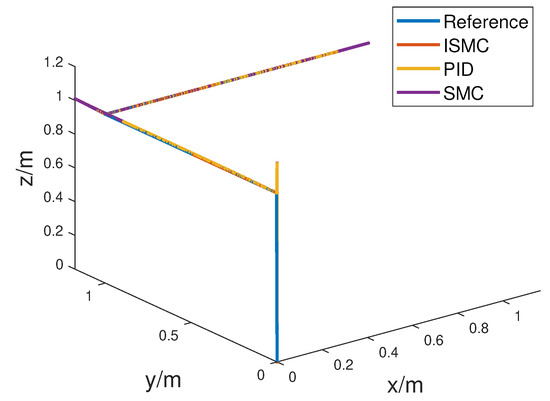
Figure 5.
Three-dimensional trajectory of UAM without disturbance utilizing the ISMC and PID.
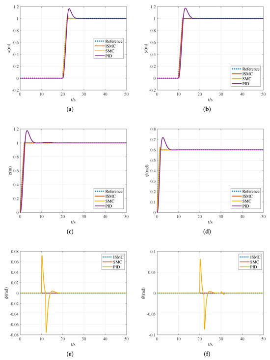
Figure 6.
Time evolution of UAM position and attitude without disturbance, where (a) position along x-axis, (b) position along y-axis, (c) position along z-axis, (d) yaw angle , (e) roll angle , and (f) pitch angle .
Figure 6a–c show the position variation in the UAM center of mass along the x-axis, y-axis, and z-axis, respectively. It can be seen that the ISMC has better tracking capabilities than the PID. The UAM position experiences a variation at the initial moment when there is a maximum tracking error of 0.01 m along the z-axis, a variation at 10 s with a maximum tracking error of 0.01 m along the y-axis, and a variation at 20 s with a maximum tracking error of 0.01 m along the x-axis. The tracking response time for all three axes is within 1 s. Compared with the PID, the tracking speed of the ISMC is increased by 80%.
Figure 6d–f depict the Euler angles tracking of the UAM, including the yaw angle , the roll angle , and the pitch angle . The angle tracking performance of the ISMC is much better than that of the PID. Because of the lateral motion of the UAM along the x-axis, the roll angle varies at 10 s, with a maximum error of rad. The pitch angle varies at 20 s due to UAM lateral motion along the x-axis, at 30 s due to the rotation of the first link, and at 40 s due to the rotation of the second link. However, the maximum tracking error for each case is about 0.01 rad. The yaw angle reaches the preset value at 2 s. The response time of ISMC is approximately 1s, which is significantly better than that of the PID. The error approaches 0 and remains at such a value in the steady state.
Figure 7 shows the time evolution of the manipulator joint angles under both the ISMC and PID controllers. In these figures, it can be seen that ISMC outperforms PID. The first joint angle exhibits fluctuations at 20 s and 30 s. The UAM system moves along the x-axis at 20 s, causing an acceleration along the x-axis, changing the pitch angle value, which in turn influences the manipulator moment. Hence, the variation curve of the first joint angle fluctuates. The maximum tracking error is about 0.01 rad. The second joint angle exhibits fluctuations at 20 s and 40 s. The UAM system moves along the x-axis at 20 s, leading to the fluctuation of the second joint angle. The maximum tracking error is also about 0.01 rad. The response time of ISMC is approximately 1 s. Compared with PID, the tracking speed when utilizing ISMC is increased by 80%. The error approaches 0 and remains at such a value in the steady state.
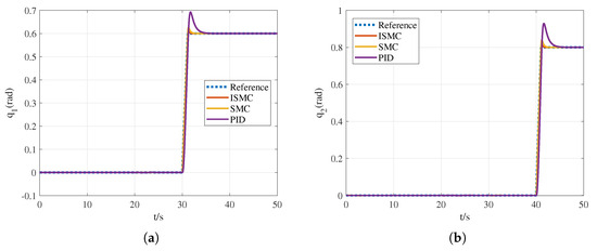
Figure 7.
Time evolution of manipulator joint coordinates without disturbance, where (a) joint angle of link 1 and (b) joint angle of link 2.
Table 2 presents the values of the control performance indices utilizing the ISMC, the SMC, and the PID. The values are obtained from the data employed to plot Figure 6 and Figure 7. As shown in Table 2, the setting time to +2% is around 1s utilizing ISMC, while the values are 5 s and 7 s when utilizing SMC and PID, respectively. The overshoot of ISMC, SMC, and PID is 1%, 3%, and 14%, respectively. The steady-state position errors of ISMC are within the region of [−0.01, 0.01] m. Among the three control methods, the PID method exhibits the largest errors and the worst convergence. The control performance of SMC is between the ISMC and PID. Therefore, the ISMC outperforms the PID and SMC in terms of both UAV trajectory tracking and manipulator joint position tracking, considering the disturbance-free scenario. In addition, the response speed is significantly improved, the overshoot is reduced by an average of about 90%, and the final error can be kept at the constant value of 0.

Table 2.
Values of control performance indices in case 1.
4.2. Case 2: External Disturbance
In this case, the hovering capability of the UAM is verified during manipulator movements in the presence of external disturbances. The desired UAM trajectories are consistent with those of case 1 in Section 4.1. Figure 8 shows the time graphic of the external disturbances that act on the UAM and on the manipulator joint angles.
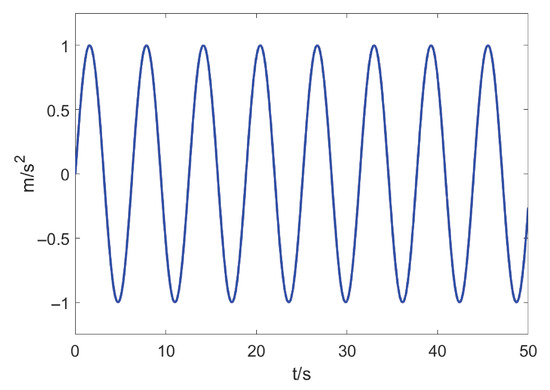
Figure 8.
Time evolution of external disturbance.
Figure 9 shows the 3D trajectory of the UAM utilizing ISMC and PID. Compared with PID, the ISMC achieves a certain improvement in control performance. The trajectory tracking outperforms that of the PID. Moreover, flight control of the UAM is achieved. Figure 10 shows the variation in the UAM states, including the positions and Euler angles of the UAM.
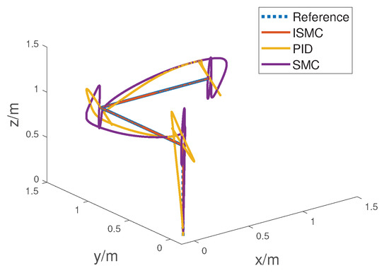
Figure 9.
Three-dimensional trajectory of UAM with external disturbance utilizing ISMC and PID.
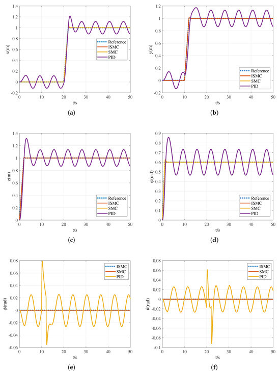
Figure 10.
Time evolution of UAM position and attitude with external disturbance, where (a) position along x-axis, (b) position along y-axis, (c) position along z-axis, (d) yaw angle , (e) roll angle , and (f) pitch angle .
Figure 10a–c show the position variation in the UAM center of mass along the x-axis, y-axis, and z-axis, respectively. The ISMC experiences a decline in the trajectory tracking performance under disturbed conditions. However, compared with the PID, the performance of the ISMC is significantly better. The tracking error is within the region of [−0.01, 0.01] m at the three axes at steady state. The UAM position experiences a variation at initial time with a maximum tracking error of m along the z-axis, a variation at 10 s with a maximum tracking error of m along the y-axis, and a variation at 20 s with a maximum tracking error of m along the x-axis. The response time for all three axes is within 1 s. Compared with PID, the tracking speed of utilizing ISMC is increased by . This serves to validate the robustness property and good tracking performance of the ISMC.
Figure 10d–f depict the Euler angle time trajectories of the UAM, including the yaw angle , the roll angle , and the pitch angle . It can be seen that the angle tracking performance remains good under disturbed conditions. The angle tracking performance of the ISMC is better than that of the PID. The pitch angle is influenced by the roll angle and the position variation in the UAM along the x- and y-axes. Compared with the PID, the curves of the ISMC have little fluctuation, and the system remains close to 0 at steady state. The yaw angle approaches the predefined value at 2 s. The stability of is almost consistent with the case without disturbances. The tracking response time period is within 1 s, and the error is within the range of [−0.01, 0.01] m.
Figure 11 shows the time evolution of the manipulator joint angles, both with ISMC and PID controllers, where it can be appreciated that ISMC outperforms PID. The maximum tracking error of both joint angles is about 0.02 rad. The error is within the range of [−0.02, 0.02] rad. The response time of ISMC is approximately 1 s. Compared with PID, the tracking speed of utilizing ISMC is increased by 80%. The error approaches 0 and remains close to 0 at steady state.
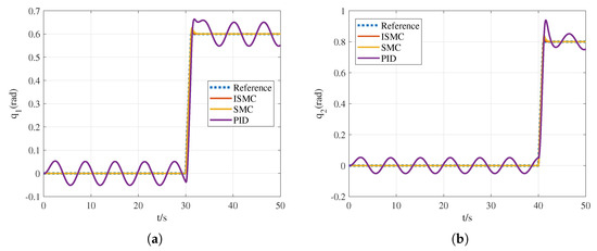
Figure 11.
Time evolution of manipulator joint coordinates with external disturbance, where (a) joint angle of link 1 and (b) joint angle of link 2.
Table 3 presents the values of control performance indices utilizing the ISMC, SMC, and PID. The values are obtained from the data employed to plot Figure 10 and Figure 11. As shown in Table 3, the setting time to +2% is about 1s utilizing ISMC, while the values are 5s and 7s when utilizing SMC and PID, respectively. The overshoot of ISMC, SMC, and PID is 1%, 3%, and 23.5%, respectively. The steady-state position errors of ISMC is within the region of [−0.01, 0.01] m. The final position error and angular error of ISMC are kept at the constant value of 0.01 m and 0.01 rad, respectively. However, the errors of PID are 0.12 m and 0.05 rad, respectively, and the errors of SMC are 0.05 m and 0.03 rad, respectively. Among the three control methods, the PID method exhibits the largest errors and the worst convergence. The control performance of the SMC method is between the performance of ISMC and PID. Therefore, the ISMC outperforms the PID and SMC in terms of both UAV trajectory tracking and manipulator joint position tracking, considering the disturbance-free scenario. In addition, the response speed is significantly improved, and the overshoot is reduced by an average of larger than 90%.

Table 3.
Values of control performance indices in case 2.
5. Discussion
The simulation results in Section 4 show that the proposed ISMC significantly outperforms PID and conventional SMC controllers in terms of tracking accuracy, convergence speed, and robustness. Compared with the PID and SMC, the ISMC reduce the RMS position error by 90% and 67%, respectively, while maintaining smoother control signals and lower chattering.
During the practical implementations, the following challenges are met:
- Actuator saturation. In practical UAM systems, the limited torque and thrust output of motors may lead to actuator saturation, especially under high external disturbances or aggressive maneuvers. This saturation can degrade tracking accuracy or even destabilize the system. We suggest incorporating anti-windup strategies and torque allocation optimization in future implementations.
- Sensor noise. Position, velocity, and attitude measurements are inevitably affected by sensor noise (e.g., IMU drift and encoder quantization). This noise can cause chattering in sliding mode control. Practical mitigation methods include low-pass filtering, adaptive smoothing, and employing disturbance observers with noise-attenuation capabilities.
- Real-time computations. Implementing ISMC on embedded processors requires ensuring that control computations are completed within the sampling time, especially when including dynamic compensation terms. Efficient code optimization and fixed-point arithmetic can be used to address this.
This discussion is intended to guide future real-world deployment of the proposed ISMC on physical UAM platforms.
6. Conclusions
This paper studies the cooperative control of an unmanned aerial manipulator (UAM) under external disturbances, where the UAM is composed of a UAV and a two-DOF manipulator. The Euler–Lagrange formulation is used to obtain the UAM dynamic model. Then, an ISMC-based controller is built. The UAM system is successfully controlled in the ideal case and in the case where external disturbances are present. Compared with the PID method, the response speed of the ISMC is significantly better. Furthermore, the overshoot is reduced by an average of about 90%, while the error approaches zero within one second and remains close to zero in the steady state.
Author Contributions
Conceptualization, S.Z. and C.W.; methodology, S.Z. and C.W.; software, A.G.–G.; validation, C.W. and A.G.–G.; formal analysis, C.W.; investigation, S.Z. and C.W.; resources, S.Z. and C.W.; writing—original draft preparation, S.Z. and C.W.; writing—review and editing, F.Z. and A.G.–G.; visualization, C.W. and W.Z.; supervision, A.G.–G.; project administration, S.Z. and A.G.–G.; funding acquisition, S.Z. and A.G.–G. All authors have read and agreed to the published version of the manuscript.
Funding
This work was supported by the National Natural Science Foundation of China (No. 62303367), the Foreign Expert Project of China (No. H20240959), the Key Research and Development Program of Shaanxi (No. 2024GX-ZDCYL-03-06), the Youth Innovation Team of Shaanxi Universities (No. 2023997), the Key Research and Development Program of Shaanxi (No. 2023-ZDLNY-61), and the Young Talent Nurturing Program of Shaanxi Provincial Science and Technology Association (No. 20240109).
Data Availability Statement
The original contributions presented in this study are included in the article. Further inquiries can be directed to the corresponding author.
Conflicts of Interest
The authors declare no conflicts of interest. The funders had no role in the design of the study; in the collection, analyses, or interpretation of data; in the writing of the manuscript; or in the decision to publish the results.
References
- Yang, S.; Xian, B. Energy-based nonlinear adaptive control design for the quadrotor UAV system with a suspended payload. IEEE Trans. Ind. Electron. 2020, 67, 2054–2064. [Google Scholar] [CrossRef]
- Xia, K.; Shin, M.; Chung, W.; Kim, M.; Lee, S.; Son, H. Landing a quadrotor UAV on a moving platform with sway motion using robust control. Control Eng. Pract. 2022, 128, 105288. [Google Scholar] [CrossRef]
- Stephens, B.; Nguyen, H.N.; Hamaza, S.; Kovac, M. An integrated framework for autonomous sensor placement with aerial robots. IEEE-ASME Trans. Mechatronics 2022, 28, 38–49. [Google Scholar] [CrossRef]
- Ollero, A.; Heredia, G.; Franchi, A.; Antonelli, G.; Kondak, K.; Sanfeliu, A.; Viguria, A.; Dios, J.R.M.-D.; Pierri, F.; Cortés, J.; et al. The aeroarms project: Aerial robots with advanced manipulation capabilities for inspection and maintenance. IEEE Robot. Autom. Mag. 2018, 25, 12–23. [Google Scholar] [CrossRef]
- Ding, C.; Lu, L. A tilting-rotor unmanned aerial vehicle for enhanced aerial locomotion and manipulation capabilities: Design, control, and applications. IEEE-ASME Trans. Mechatronics 2020, 26, 2237–2248. [Google Scholar] [CrossRef]
- Meng, X.; He, Y.; Gu, F.; Yang, L.; Dai, B.; Liu, Z.; Han, J. Design and implementation of rotor aerial manipulator system. In Proceedings of the IEEE International Conference on Robotics and Biomimetics, Qingdao, China, 3 December 2016. [Google Scholar]
- Clark, A.B.; Baron, N.; Orr, L.; Kovac, M.; Rojas, N. On a balanced delta robot for precise aerial manipulation: Implementation, testing, and lessons for future designs. In Proceedings of the IEEE International Conference on Intelligent Robots and Systems, Kyoto, Japan, 23 October 2022. [Google Scholar]
- Bodie, K.; Tognon, M.; Siegwart, R. Dynamic end effector tracking with an omnidirectional parallel aerial manipulator. IEEE Robot. Autom. Lett. 2021, 6, 8165–8172. [Google Scholar] [CrossRef]
- Gao, H.; Li, Z.; Yu, X.; Qiu, J. Hierarchical multiobjective heuristic for PCB assembly optimization in a beam-head surface mounter. IEEE Trans. Cybern. 2021, 52, 6911–6924. [Google Scholar] [CrossRef]
- Cao, H.; Li, Y.; Liu, C.; Zhao, S. ESO-based robust and high-precision tracking control for aerial manipulation. IEEE Trans. Autom. Sci. Eng. 2023, 21, 2139–2155. [Google Scholar] [CrossRef]
- Lin, J.; Miao, Z.; Zhong, H.; Peng, W.; Wang, Y.; Fierro, R. Adaptive image-based leader–follower formation control of mobile robots with visibility constraints. IEEE Trans. Ind. Electron. 2020, 68, 6010–6019. [Google Scholar] [CrossRef]
- Liu, Y.C.; Dao, P.N.; Zhao, K.Y. On robust control of nonlinear teleoperators under dynamic uncertainties with variable time delays and without relative velocity. IEEE Trans. Ind. Inform. 2019, 16, 1272–1280. [Google Scholar] [CrossRef]
- Qi, G.; Li, X.; Chen, Z. Problems of extended state observer and proposal of compensation function observer for unknown model and application in UAV. IEEE Trans. Syst. Man Cybern. Syst. 2022, 52, 2899–2910. [Google Scholar] [CrossRef]
- Lopez-Lora, A.; Sanchez-Cuevas, P.; Suárez, A.; Garofano-Soldado, A.; Ollero, A.; Heredia, G. MHYRO: Modular HYbrid RObot for contact inspection and maintenance in oil & gas plants. In Proceedings of the International Conference on Intelligent Robots and Systems, Las Vegas, NV, USA, 24 October 2020. [Google Scholar]
- Garimella, G.; Sheckells, M.; Kim, S.; Baraban, G.; Kobilarov, M. Improving the reliability of pick-and-place with aerial vehicles through fault-tolerant software and a custom magnetic end-effector. IEEE Robot. Autom. Lett. 2021, 6, 7501–7508. [Google Scholar] [CrossRef]
- Yigit, A.; Perozo, M.; Cuvillon, L.; Durand, S.; Gangloff, J. Novel omnidirectional aerial manipulator with elastic suspension: Dynamic control and experimental performance assessment. IEEE Robot. Autom. Lett. 2021, 6, 3612–3619. [Google Scholar] [CrossRef]
- Watson, R.; Kamel, M.; Zhang, D.; Dobie, G.; MacLeod, C.; Pierce, S.G.; Nieto, J. Dry coupled ultrasonic non-destructive evaluation using an over-actuated unmanned aerial vehicle. IEEE Trans. Autom. Sci. Eng. 2021, 19, 612–619. [Google Scholar] [CrossRef]
- Liu, C.; Zhang, G.; Xiong, A. Review of researches on aerial manipulator. Chin. High Technol. Lett. 2020, 30, 612–619. [Google Scholar]
- Sun, Y.; Jing, Z.; Dong, P.; Huang, J.; Chen, W.; Leung, H. A switchable unmanned aerial manipulator system for window-cleaning robot installation. IEEE Robot. Autom. Lett. 2021, 6, 3483–3490. [Google Scholar] [CrossRef]
- Yigit, A.; Perozo, M.; Cuvillon, L.; Durand, S.; Gangloff, J. Improving dynamics of an aerial manipulator with elastic suspension using nonlinear model predictive control. In Proceedings of the IEEE International Conference on Robotics and Automation, Xi’an, China, 30 May 2021. [Google Scholar]
- Meng, X.; He, Y.; Han, J. Survey on aerial manipulator: System, modeling, and control. Robotica 2020, 38, 1288–1317. [Google Scholar] [CrossRef]
- Ma, Z.; Sheng, X.; Dong, W. Robust Flight Control of an Aerial Manipulator. Mach. Des. Res. 2020, 36, 6–11. [Google Scholar]
- Ollero, A.; Tognon, M.; Suarez, A.; Lee, D.; Franchi, A. Past, present, and future of aerial robotic manipulators. IEEE Trans. Robot. 2021, 38, 626–645. [Google Scholar] [CrossRef]
- Meng, X. Modeling and Control of Aerial Manipulators in Contact Operation. Ph.D. Thesis, Shenyang Institute of Automation, Shenyang, China, 2019. [Google Scholar]
- Mo, R.; Cai, H.; Dai, S.L. Unit Quaternion Based Attitude Control of An Aerial Manipulator. In Proceedings of the International Federation of Automatic Control, Chengdu, China, 25 September 2019. [Google Scholar]
- Johansen, T.A.; Andersen, T.S.; Kristiansen, R. PD+ based trajectory tracking of the underactuated quadrotor platform using dual quaternions. In Proceedings of the American Control Conference, Philadelphia, PA, USA, 10 July 2019. [Google Scholar]
- Mimmo, N.; Macchelli, A.; Naldi, R.; Marconi, L. Robust motion control of aerial manipulators. Annu. Rev. Control 2020, 49, 230–238. [Google Scholar] [CrossRef]
- Caccavale, F.; Giglio, G.; Muscio, G.; Pierri, F. Adaptive control for UAVs equipped with a robotic arm. In Proceedings of the International Federation of Automatic Control, Cape Town, South Africa, 24 August 2014. [Google Scholar]
- Ruggiero, F.; Trujillo, M.A.; Cano, R.; Ascorbe, H.; Viguria, A.; Perez, C.; Lippiello, V.; Ollero, A.; Siciliano, B. A multilayer control for multirotor UAVs equipped with a servo robot arm. In Proceedings of the IEEE International Conference on Robotics and Automation, Seattle, WA, USA, 26 May 2015. [Google Scholar]
- Kim, M.; Kondak, K.; Ott, C. A stabilizing controller for regulation of uav with manipulator. IEEE Robot. Autom. Lett. 2018, 3, 1719–1726. [Google Scholar] [CrossRef]
- Lee, H.; Kim, H.J. Estimation, control, and planning for autonomous aerial transportation. IEEE Trans. Ind. Electron. 2016, 64, 3369–3379. [Google Scholar] [CrossRef]
- Kim, S.; Choi, S.; Kim, H.; Shin, J.; Shim, H.; Kim, H.J. Robust control of an equipment-added multirotor using disturbance observer. IEEE Trans. Control Syst. Technol. 2017, 26, 1524–1531. [Google Scholar] [CrossRef]
- Brunner, M.; Rizzi, G.; Studiger, M.; Siegwart, R.; Tognon, M. A planning-and-control framework for aerial manipulation of articulated objects. IEEE Robot. Autom. Lett. 2022, 7, 10689–10696. [Google Scholar] [CrossRef]
- Miao, Z.; Zhong, H.; Lin, J.; Wang, Y.; Chen, Y.; Fierro, R. Vision-based formation control of mobile robots with FOV constraints and unknown feature depth. IEEE Trans. Control Syst. Technol. 2020, 29, 2231–2238. [Google Scholar] [CrossRef]
- Chang, Z.; Luo, Y.; Shao, Y.; Chu, H.; Wu, B.; Huang, M.; Rao, Y. Fuzzy sliding mode control for rotorcraft aerial manipulator with extended state observer. In Proceedings of the 2020 Chinese Automation Congress (CAC), Shanghai, China, 6–8 November 2020; pp. 1710–1714. [Google Scholar]
- Li, Z.; Xiu, B.; Li, Z.; Yu, X.; Rodríguez-Andina, J.J. Nonlinear characteristic model-based discrete-time sliding mode control for the hovering flight of an aerial manipulator. IEEE Trans. Ind. Electron. 2025; early access. [Google Scholar] [CrossRef]
- Chen, Y.; Liang, J.; Wu, Y.; Miao, Z.; Zhang, H.; Wang, Y. Adaptive sliding-mode disturbance observer-based finite-time control for unmanned aerial manipulator with prescribed performance. IEEE Trans. Cybern. 2023, 53, 3263–3276. [Google Scholar] [CrossRef]
- D’Angelo, S.; Selvaggio, M.; Lippiello, V.; Ruggiero, F. Semi-autonomous unmanned aerial manipulator teleoperation for push-and-slide inspection using parallel force/vision control. Robot. Auton. Syst. 2025, 186, 104912. [Google Scholar] [CrossRef]
- Yu, S.; Guo, Y.; Wang, Z.; Hao, Z. Rapid robust trajectory tracking control for oscillatory-base manipulators via enhanced terminal sliding mode and scleronomic Lagrangian mechanics-informed neural networks. Appl. Ocean Res. 2025, 162, 104705. [Google Scholar] [CrossRef]
- Kumar, S.; Dwivedy, S. Neuro compensated sliding mode control with nonlinear surfaces for pipe crack sealing manipulator. Robot. Auton. Syst. 2025, 190, 104997. [Google Scholar] [CrossRef]
- Dou, B.; Yue, X. Disturbance observer-based fractional-order sliding mode control for free-floating space manipulator with disturbance. Aerosp. Sci. Technol. 2025, 132, 108061. [Google Scholar] [CrossRef]
Disclaimer/Publisher’s Note: The statements, opinions and data contained in all publications are solely those of the individual author(s) and contributor(s) and not of MDPI and/or the editor(s). MDPI and/or the editor(s) disclaim responsibility for any injury to people or property resulting from any ideas, methods, instructions or products referred to in the content. |
© 2025 by the authors. Licensee MDPI, Basel, Switzerland. This article is an open access article distributed under the terms and conditions of the Creative Commons Attribution (CC BY) license (https://creativecommons.org/licenses/by/4.0/).