Article

Experiment and Numerical Investigation of a Forebody Design Method for Inward-Turning Inlet

1
College of Energy and Power Engineering, Nanjing University of Aeronautics and Astronautics, Nanjing 210016, China
2
National Key Laboratory of Ramjet, China Aerodynamics Research and Development Center, Mianyang 621000, China
3
Research and Development Center, China Academy of Launch Vehicle Technology, Beijing 100076, China
*
Author to whom correspondence should be addressed.
Aerospace 2025, 12(9), 763; https://doi.org/10.3390/aerospace12090763 (registering DOI)
Submission received: 30 June 2025 / Revised: 12 August 2025 / Accepted: 21 August 2025 / Published: 26 August 2025
(This article belongs to the Special Issue High Speed Aircraft and Engine Design)

Abstract

The integration of three-dimensional inward-turning inlets with airframes has broad application prospects. This paper develops an integrated design method for the inlet forebody with a controllable incident shock wave shape, aiming at the three-dimensional inward-turning inlet with a circular entrance, and it is applied to the forebody design of a given inward-turning inlet to obtain a three-dimensional inward-turning inlet/forebody matching scheme. Numerical simulation and wind tunnel experiment were carried out to investigate the aerodynamic performance of the inlet. The results show that the inlet/forebody matching scheme successfully realizes both geometric and aerodynamic matching between the inlet and forebody, resulting in a shock-on-lip condition at the design point, with only a 2% reduction in mass flow rate. This indicates that the forebody design and matching method are highly effective. It should be noted that after the forebody matching is achieved, the overall compression effect of the inlet on the airflow is weakened, and both the Mach number and total pressure at the inlet outlet increase slightly.

1. Introduction

The function of the inlet is to compress the incoming flow and provide compressed, high-quality airflow for the downstream engine. In recent years, some three-dimensional inward-turning inlets, which differ from traditional inlets, have attracted more and more attention [1,2]. Integrated design with the aircraft forebody has become a hotspot research topic [3,4]. One of the ideas proposed by Kothari et al. [5] is to directly use the inward-turning inlet as the aircraft forebody, which is mostly used in missiles. It fuses the three-dimensional inner-constriction inlet with the aircraft forebody completely and has a high degree of integration characteristics. However, since the reference flow field is designed with the internal conical flow field, the lift-drag characteristics will be seriously affected, so it is necessary to configure a waverider forebody for this kind of inward-turning inlet.
For traditional inlets, such as typical two-dimensional inlets, their forebody design and matching work can be carried out from a two-dimensional perspective. In related research, some scholars have already achieved the integrated design of the forebody and the inlet ramp profile [6]. However, due to limitations in its design methods, the three-dimensional inward-turning inlet still lacks a mature integrated design approach. Some researchers have attempted to first conduct numerical simulations on the waverider forebody to obtain the flow field after compression by the waverider forebody and then use the flow information as input to design the inward-contraction inlet while ignoring flow uniformity [7]. Therefore, achieving the matching between the forebody and the inlet remains an important research topic.
As far as the waverider is concerned, there are three main design methods. The first one is the inverse design method. This method is based on the reference flow field generated by the shock-generating body and then obtains the shape of the waverider body according to streamline tracing, such as wedge-derived waveriders [8,9], cone-derived waveriders [10], etc. The second method is the designated shock wave method. Compared to the first method, this method can specify the shape of the shock wave and use the constructed osculating plane to design the waverider, which has higher flexibility, such as the Osculating Cone Method and the Osculating Axisymmetry Method [11,12]. The third method is the fixed/variable wedge angle design method, which differs from the former two. It is a forward design method [13] that constructs different two-dimensional wedge flows along the spanwise direction of the waverider body and designs the waverider configuration according to the corresponding constraints. These waverider design methods have been relatively mature. However, when it comes to directly applying them to the matching work with three-dimensional inward-contraction inlets, the issue of coupling between the profiles and flow fields of the inlet and the forebody remains to be resolved.
Thus, this paper intends to investigate a method for forebody design and matching under the geometric constraints of an inlet. This method is comparable to the forebody-matching approach in the aforementioned work [7], where the inlet is designed given a forebody. However, our work operates conversely; we hold that designing the forebody based on a specified inlet is also a viable forebody-matching method. While developing this method, we also aim to understand the impact on inlet performance after forebody matching is achieved.

2. Forebody Design Method Matching with Inlet

The forebody design method used in this paper starts from the two-dimensional wedge flow field and inversely designs the curved-wall forebody according to the leading-edge curved shock wave shape. It then modifies the forebody profile, combined with geometric constraints, to achieve a matching design of the forebody and the three-dimensional inward-turning inlet. The rough design process is shown in Figure 1.

2.1. Method of Characteristic

The supersonic flow downstream of the curved shock wave formed at the leading edge of an object moving at supersonic speed belongs to rotational isentropic flow (where entropy along the streamline is constant, and there can be gradients of entropy and stagnation parameters in the direction perpendicular to the streamline). The flow field can be solved by the characteristic line method. The Method of Characteristic (MOC) [14] is to transform nonlinear partial differential equations into ordinary differential equations for solution and to use characteristic line equations (shown in Formula (1)) and compatibility relations (shown in Formula (2)) instead of quasi-linear partial differential equations.
(1)
Characteristic equation:
( d y d x ) ± = λ ± = tan ( θ ± μ ) ( d y d x ) 0 = λ 0 = v u
(2)
Consistency equation:
M 2 1 ρ V 2 d p ± ± d θ ± ± δ sin θ d x ± y M cos ( θ ± μ ) = 0 ρ V d V + d p = 0 d p a 2 d ρ = 0
where δ = 0 denotes two-dimensional plane flow, δ = 1 denotes two-dimensional axisymmetric flow, p, ρ, a, μ, α, V, and M are static pressure, density, sound velocity, flow angle, Mach angle, velocity, and Mach number, respectively; u and v, respectively, represent velocity components in XY direction; the subscripts 0 and ±denote the streamline and the two Mach lines, respectively.
An iterative Euler correction algorithm is used in each computational procedure to improve the accuracy of the solution.

2.2. Introduction of the Inverse Characteristic Line Method Based on Shock Wave Shape

2.2.1. Inviscid Design

The traditional characteristic line method is a forward solution process, with the flow condition as the initialization parameter and the compression surface as the boundary condition. It simultaneously solves the characteristic line equations and compatibility equations along the characteristic line and pushes them downstream to obtain the solution of the entire flow field. However, the idea of a reverse solution is that, on the contrary, this method usually gives a parameter distribution on the wall [15,16], a curved shock wave parameter [17,18,19], or a reflected shock wave parameter [20], and then combines the characteristic line method to solve the compression wall in reverse.
The schematic diagram of solving the wall boundary points is shown in Figure 2a. Knowing the geometric parameters and flow field parameters of initial points 2 and 3, the streamline emitted by point 3 first intersects the reverse left characteristic line emitted by point 2 at point 4. The coordinates of point 4 can be obtained according to the characteristic line equation. Then, the coordinates and flow field parameters of point 1 can be determined from the intersection of the reverse right line of point 4 and the connecting lines between points 2 and 3. Then, the flow field parameters of point 4 can be solved through the compatibility equation of point 4 characteristic lines. Finally, the correction method is used to improve the calculation accuracy of point 4. Figure 2b is a schematic diagram of the space marching method, in which the blue curve (OD) is the shape of the known curved shock wave, and the red curve (OD’) is the wall boundary designed by the inverse characteristic method. The parameters behind the curved shock wave are solved according to the free flow condition, the shape of the curved shock wave, and the oblique shock wave relation, along the direction of the shock wave to the wall boundary. The computational procedure of the inner point is recycled layer by layer, and finally, the solution of the whole flow field and the shape of the compression wall OD’ are obtained.
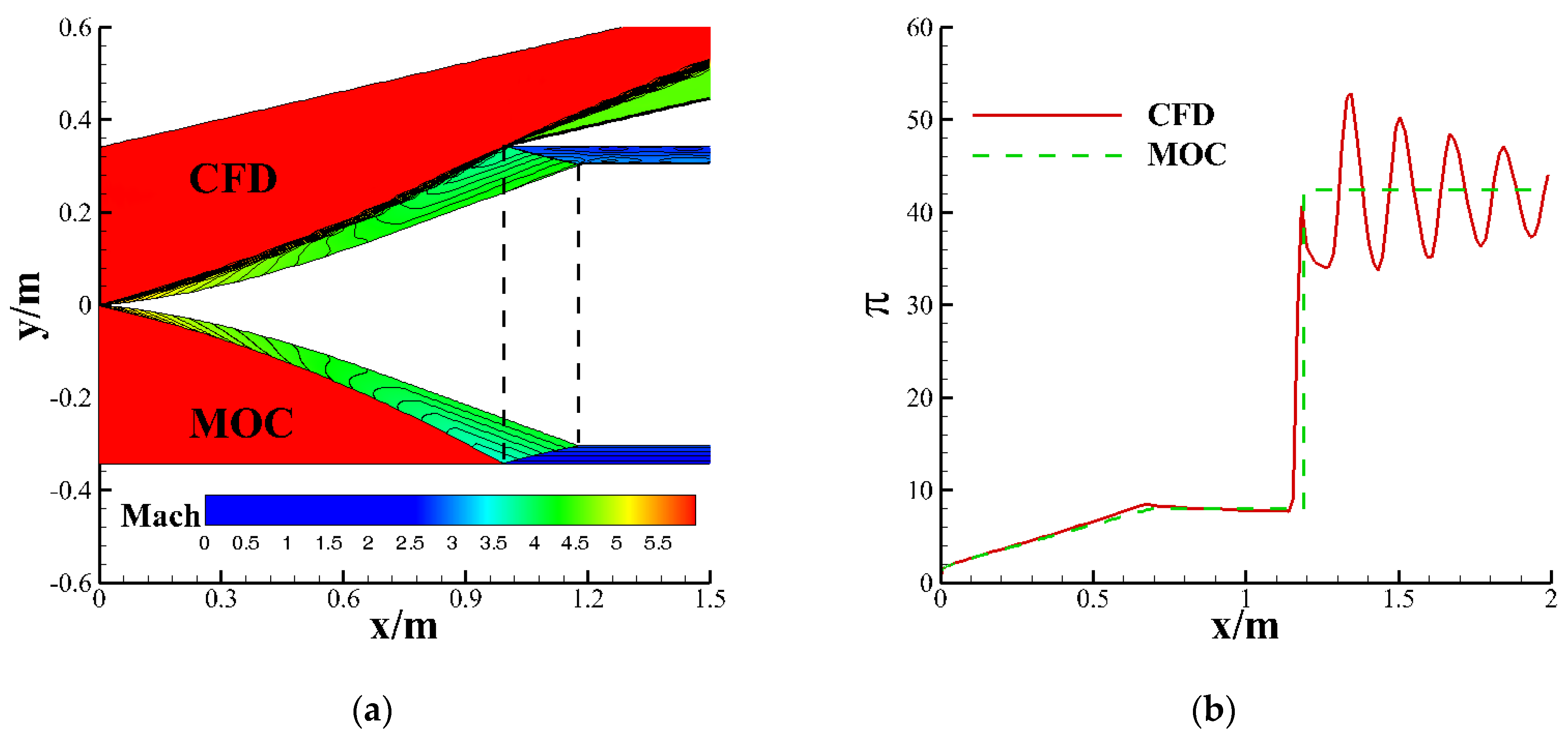
The ramp profile generated by the program is extracted for two-dimensional inviscid CFD verification to verify the accuracy of the MOC. Figure 3 shows the comparison of the Mach number contour of the flow field and the static pressure distribution along the way obtained by the MOC and CFD methods, respectively. From the graph, we can see that the CFD result is consistent with the MOC before the reflected shock wave. However, the pressure fluctuates significantly after the reflected shock wave, mainly because it does not accurately hit the shoulder point, thus forming a series of reflected shock waves in the path, which causes the wall pressure to oscillate.

2.2.2. Boundary Layer Correction

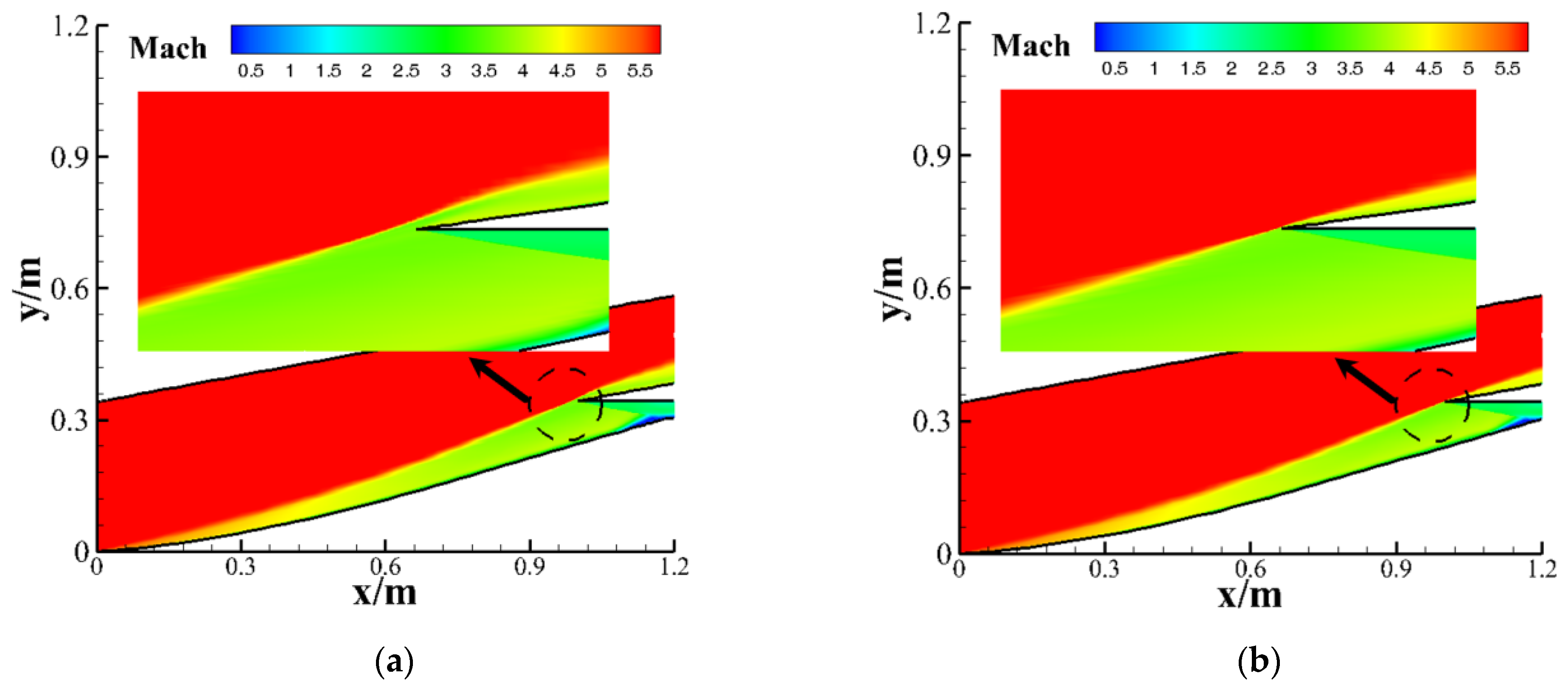
In this paper, Formula (3) is used to correct the boundary layer. Figure 4 presents the Mach number contour of the inlet flow field before and after correction, as well as the local enlarged view of the lip in the dashed circle, obtained from viscous numerical simulations. It can be seen from the figure that after considering the viscosity, the existence of the boundary layer increases the actual flow deflection angle, the leading-edge curved shock wave angle increases, the curved shock no longer on the lip, and supersonic overflow occurs at the lip. After boundary layer correction, the leading-edge curved shock forms on the lip, which means the realization of the correction effect.
δ x = 0.382 0.382 Re x 1 / 5

2.3. Design of Forebody Profile on Symmetrical Plane

In the process of inlet and forebody matching design on symmetrical cross section, on the one hand, it is necessary to ensure geometric matching, that is, the geometric smooth transition between the forebody and the inlet, and to avoid the generation of the second curved shock wave as far as possible; on the other hand, it is necessary to ensure the aerodynamic matching, that is, the inlet with the forebody can still achieve shock on lip in the design state. This requires the design of a reasonable curved shock wave. The curved shock wave in this paper is a polynomial curve assumed according to the geometric constraints, which is directly related to the matching between the designed forebody and the inlet.
As can be seen from the inverse design schematic of Figure 2, the end of the basic flow field is a reverse left characteristic line emitted by point D. By the characteristic decomposition and the simple wave, it is found that any wave adjacent to a constant state is a simple wave whose flow region is covered by a one-parametric family of independent lines, along each of which the static pressure and the velocity are constants. The straight line DD’ is such a simple wave, so the velocity direction of point D is the same as that of point D’. Therefore, when designing the curved shock wave shape, the smooth connection between the forebody and the inlet can be achieved by ensuring that the velocity direction behind the wave at point D is equal to the initial compression angle of the leading edge of the inlet.
As shown in Figure 5a, the solid line 23 represents the curved shock wave, and point 4 shows the connection between the inlet and the forebody. Based on the above analysis, δwall = δshock, substituting δshock into the oblique shock wave relation to calculate βshock, that is, the slope of the curved shock wave at point 2. Combined with the initial geometric constraints of the inward-turning inlet, the curved shock wave satisfying the aerodynamic matching of the inlet and the forebody can be preliminarily designed, such as the line OA shown in Figure 5b. Since the curved shock wave OA is generated only by the compression surface of the forebody, the influence of the inlet is not taken into account. After adding the forebody, the actual curved shock wave will further bend upward due to inlet compression, and the shock wave will no longer attach to the cowl lip and be transformed into a curved shock wave OB. At this time, the distance between the shock wave and the lip is AB = H, so the end height of the curved shock wave should be reduced by H and then redesigned to finally obtain the curved shock wave OC that can approximately attach to the cowl lip. Combined with the method of Section 2.2, the compression wall OP, that is, the cross-sectional profile of the forebody at the symmetry plane, can be designed.

2.4. Three-Dimensional Forebody Generation Scheme

The cross-sectional profile of the forebody at the symmetry plane can be obtained by the method described in Section 2.3. In order to obtain a three-dimensional waverider forebody, one idea is to select several planes along the spanwise direction to split the inlet, then sequentially generate two-dimensional curved compression profiles in these planes, and then integrate all curved wall profiles into a three-dimensional forebody, as shown in Figure 6a. However, this method is not applicable to a three-dimensional inward-turning inlet with a given geometric constraint. Another idea is to scan the leading-edge line of the inlet along the forebody cross-section profile at the symmetry plane, then select a projection direction (such as top-down in the figure below), and use a certain geometric shape to intercept the scanned plane (this paper uses an ellipse to intercept), as shown in Figure 6b. This method is an approximate method with wide applicability.
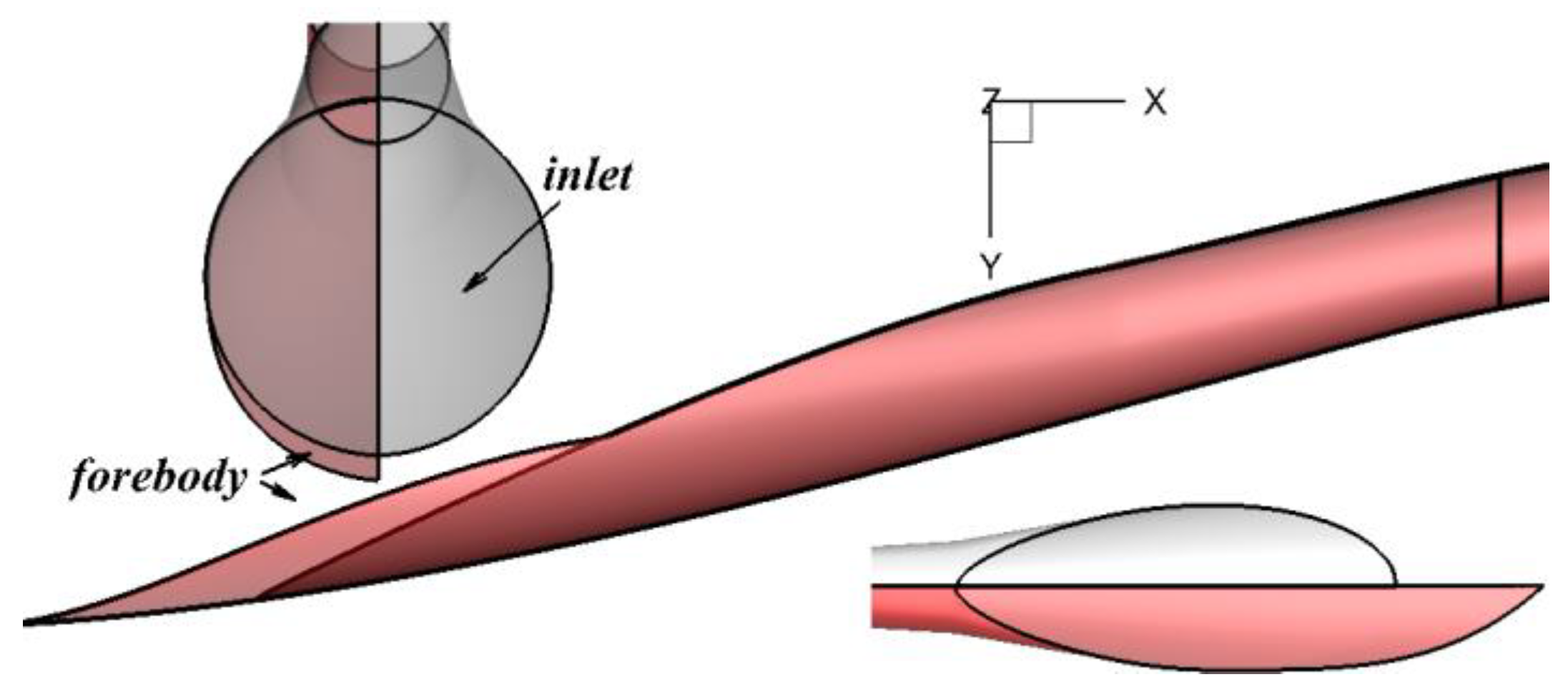
In this paper, the second method above is used to generate the three-dimensional forebody shown in Figure 7, where the gray part represents the original scheme without the forebody (given configuration), and the red part represents the three-dimensional inward-turning inlet forebody matching scheme. As can be seen from the figure, the three-dimensional inward-turning inlet with a circular capture shape has little overall difference after adding a forebody. It is still approximately circular in capture from front to back, and the overall length of the inlet has been slightly lengthened.

3. Introduction to Numerical Simulation and Wind Tunnel Experiment

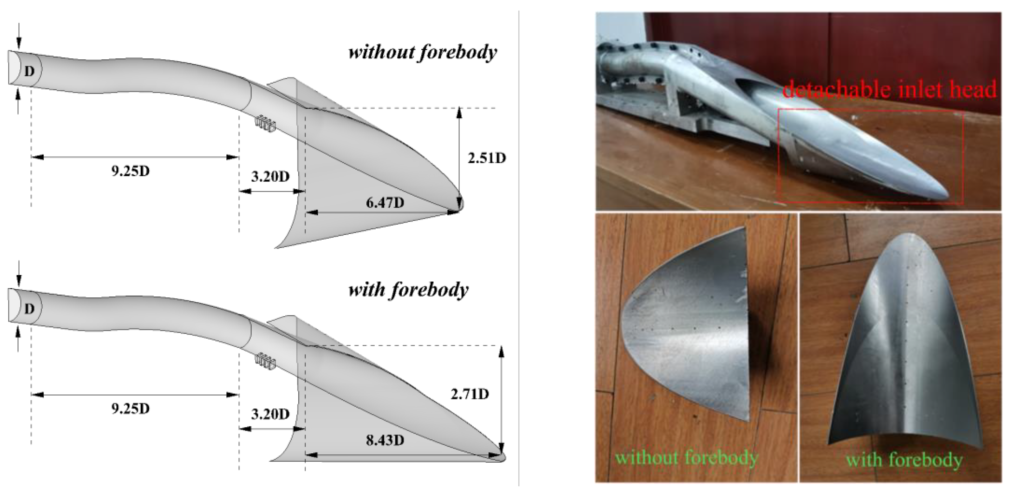
In this study, the initial inlet without a forebody is an inward-turning inlet with a circular capture shape, and the design Mach number is 6. The geometric size of the inlet is dimensionless processed by outlet diameter D. the total length of the inlet is 18.92 D, the external compression segment is 6.47 D, the internal compression segment is 3.20 D, the isolator is 9.25 D, and the throat diameter and outlet diameter are both D. After adding the forebody, length of the external compression segment increases to 8.43 D. Four suction slots with a width of about 0.07 D are set at the shoulder of the internal compression segment to improve the self-starting and restarting ability of the inlet. Figure 8 shows the geometric configuration and experimental model of the inlet studied in this paper. The detailed research methods for the configuration of the inlet without a forebody were reported in an earlier work by our research group [21]. In that study, the simulation strategy and experimental process were introduced in detail, and the simulation and experimental data for the inlet configuration without a forebody were provided. This paper adopts the same numerical simulation strategy as that work (including grid division strategy and numerical solution method, etc.) and supplements the work content of the inlet configuration with the forebody. In the design of the inlet experimental model without a forebody, we set the inlet head part of the original experimental model as a detachable component. Therefore, the inlet experimental model with a forebody can be obtained simply by replacing the detachable component with the forebody component.

3.1. Wind Tunnel Experiment

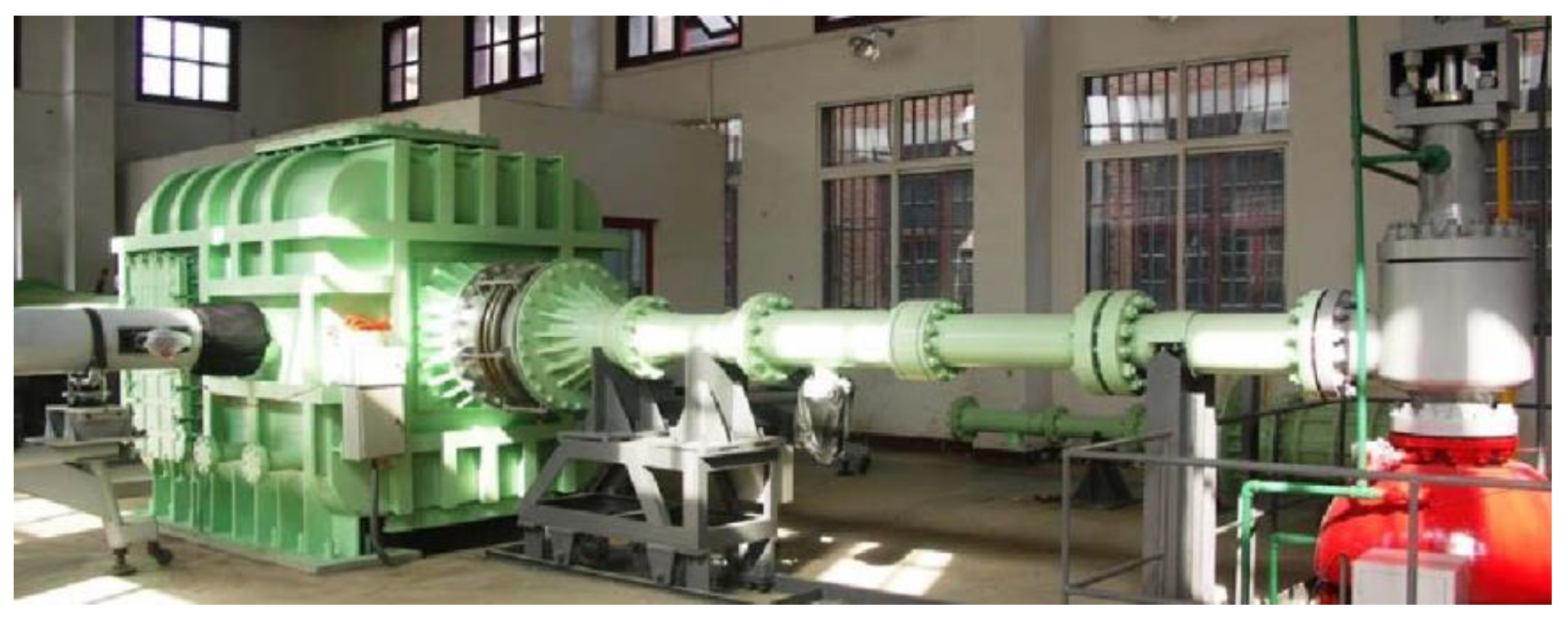
This research experiment was conducted in the NHW hypersonic wind tunnel at Nanjing University of Aeronautics and Astronautics. The NHW wind tunnel is an intermittent cold-flow wind tunnel (as shown in Figure 9).
Its essential design Mach numbers are 5 and 8. The upstream-chamber stagnation pressure is 1 MPa, the stagnation temperature is 685 K, and the running time is more than 10 s. The wind tunnels are heated with the storage heater. The testing Mach numbers 5, 6, 7, and 8 are realized by using the contour nozzle with an exit diameter of 0.5 m. This test is mainly carried out under Ma5 and Ma6, and the specific inflow conditions are shown in Table 1 below.
A large number of static pressure measuring holes are arranged in the inlet inner path to measure the static pressure distribution and monitor the position of the terminal shock. Of these 26 measuring points on the upper wall are marked U1–U26, and 42 measuring points on the lower wall are marked L1–L42. The above static pressures are measured by the PSI9001 series pressure scanners developed by American Pressure System® (PSI International, Fairfax, VA, USA) at a frequency of 10 Hz. In order to obtain the oscillation characteristics of the shock train and inlet unstart, a high-frequency dynamic pressure sensor is used to record the wall pressure fluctuations of the inlet at a frequency of 10 KHz. The distribution of dynamic measuring points is shown in Figure 10, with six on the upper and lower walls (DU1–DU6, DL1–DL6).

3.2. Numerical Simulation

The governing equations for steady compressible flows of a continuous medium, based on the principles of mass conservation, momentum conservation, and energy conservation, apply to steady flows where density varies with flow conditions (physical quantities are time-independent). In Cartesian coordinates, they are expressed as follows:
Continuity Equation:
x i ρ u i = 0
Momentum Equations:
x j ρ u i u j = p x i + τ i j x j
τ i j = μ u i x j + u j x i 2 3 μ u l x l δ i j
Energy Equation:
x i u i ρ E + p = x j k e f f T x j + x j τ e f f ¯ u j
Herein, keff is the thermal conductivity, and the second term on the right-hand side is the viscous dissipation term.
The three-dimensional Reynolds-Averaged Navier-Stokes equations are solved with a finite volume spatial discretization method. The turbulent flow is modeled by using the two-equation sst-kω. The governing equation was discretized by a second-order upwind Roe-flux-difference splitting (FDS) scheme, and the gradient was calculated based on the least-squares cell-based method. The LU-SGS method is used for time marching. The airflow is set as a compressible ideal gas. The Reynolds-Averaged Navier-Stokes (RANS) model can only simulate the time-averaged flow field and struggles to reflect the coherent structures, unsteady fluctuations, and transient interactions in three-dimensional turbulence. However, it is sufficiently applicable to the engineering application scenarios studied in this paper, which is supported by the subsequent experimental and simulation comparison work in this paper.
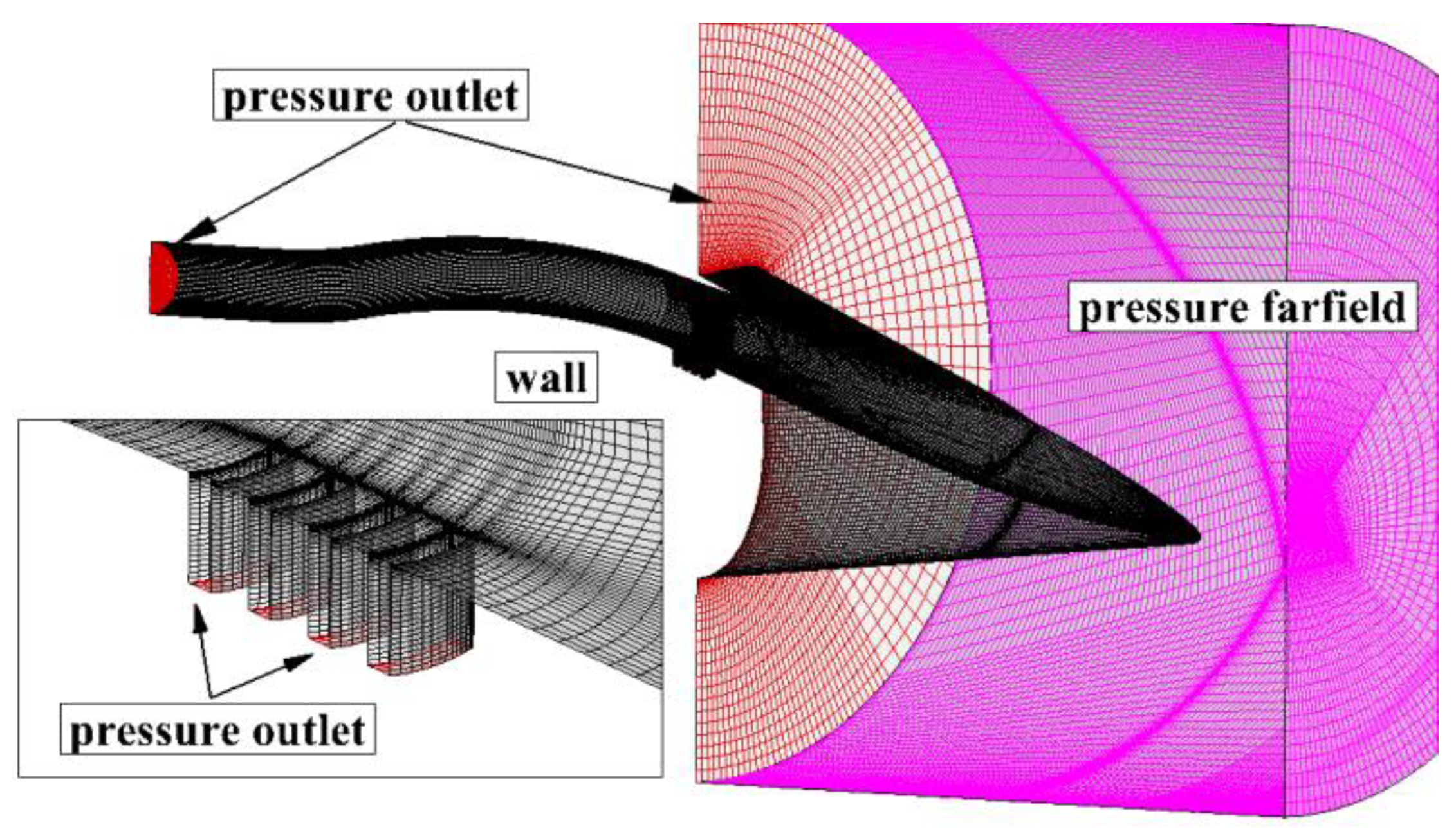
Figure 11 illustrates the setting of boundary conditions and the structured grid in numerical computation, and grid refinement is performed in areas where the flow parameters change drastically, such as shock waves and walls. Owing to the symmetry of the geometric configuration, the computational domain chosen is half of the actual one, which can reduce computational complexity. Finally, the number of structured grid cells in the half-model is kept at around 1,500,000.

4. Results and Discussion

4.1. Result of the Wind Tunnel Experiment

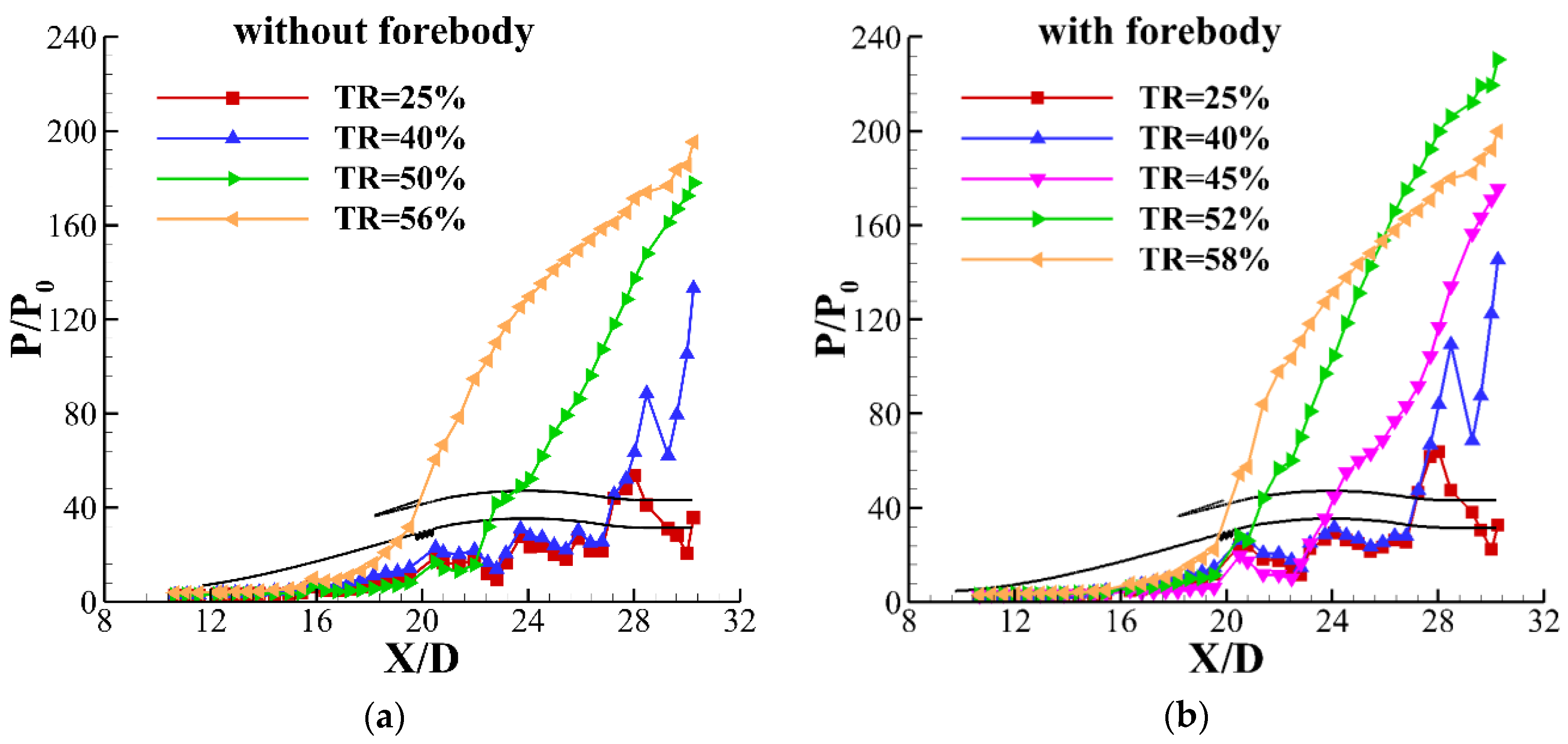
Figure 12 shows the pressure distribution along the upper and lower walls of the inlet with different throttling ratios at an oncoming Mach 6, zero angle of attack, in which figure (a) shows the original configuration without a forebody and figure (b) shows the optimized configuration after adding a forebody. The inlet geometry size was dimensionless, treated using the outlet diameter D of the outlet. The X-coordinate and Y-coordinate indicate the distance and pressure along the wall, respectively, and different curves indicate different throttling ratios (TRs). The position of the shock train is obtained according to the start position of the pressure rise. It can be seen from the diagram that the backpressure characteristics of the two inlet configurations are similar (there is little difference in the position of the throttle cone), showing a similar change rule. The change of cone position only affects the pressure distribution of the isolator and does not change the pressure distribution of the external pressure segment. When the TR is equal to 25%, there is no sharp increase in pressure in the isolator of the two configurations; therefore, it is preliminarily determined that the shock train has not formed, and the supersonic flow goes through the whole flow path. When the TR increases to 40%, the pressure in the downstream of the isolator of the two configurations suddenly increases and forms a shock train. As the TR increases, the terminal shock waves continue to move upstream. When the TR of the configuration with and without forebody reaches 50% and 52%, respectively, the terminal shock arrives at the throat. Once the backpressure continues to increase, both configurations of the inlet will unstart. Therefore, the TR = 25% is selected as the inlet through-flow status of both configurations.
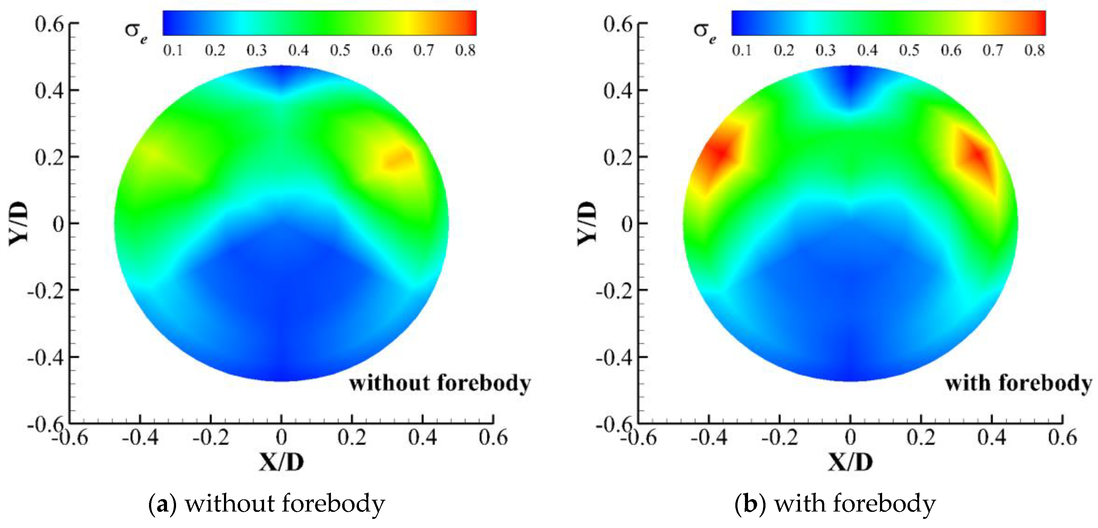
Figure 13 shows the distribution of the total pressure recovery coefficient at the inlet and outlet under the through-flow status with the incoming flow Mach numbers 6, zero angle of attack, where figure (a) shows the original configuration without a forebody, and figure (b) shows the optimized configuration after adding a forebody. As can be seen from the figure, the total pressure distribution of the two inlet configurations is similar in the fully open state, and both of them are symmetrical along the median line. There are large-scale low-energy flow regions on the lower wall side of the two inlet configurations, and the total pressure recovery coefficient is low, while a small-scale high-energy flow region appears on the left and right sides. Compared to the configuration without a forebody, the region of high energy flow at the outlet of the configuration with a forebody is larger, and the total pressure recovery coefficient is higher. From the analysis of experimental data, the outlet total pressure recovery coefficient of the inlet configuration without a forebody is 0.29, while that of the inlet configuration with a forebody is 0.31.

4.2. Numerical Simulation Validation

Since there is no observation window in the experimental internal pressure segment and isolator, the specific flow field in the internal path cannot be observed. Therefore, the flow field can be predicted by means of numerical simulation results combined with experimental data.
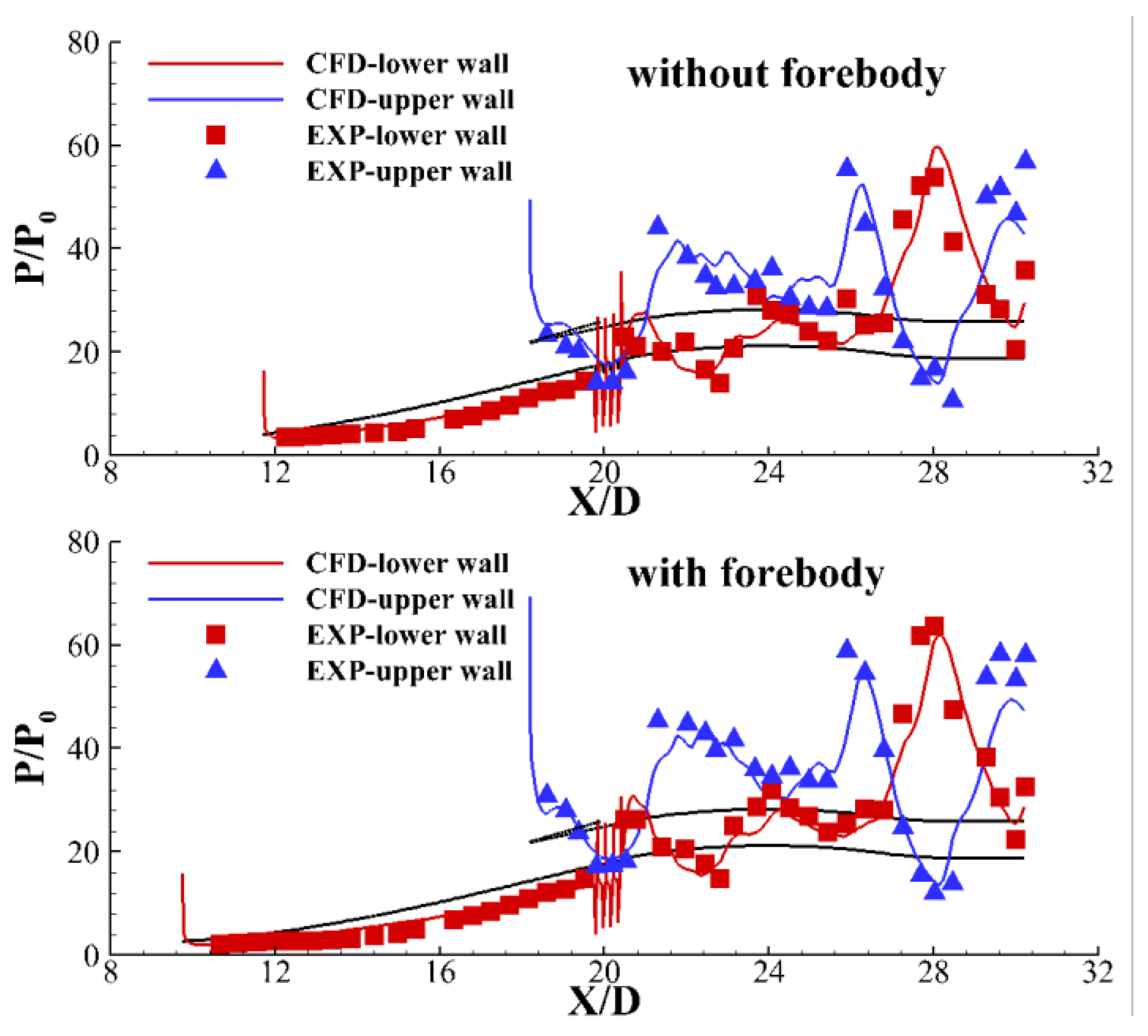
Figure 14 shows the static pressure distribution along the path of the two inlet configurations at a free stream flow Mach 6, where the discrete points denote the experimental data and the curves denote the numerical simulation results. Table 2 shows the comparative results of the outlet performance of the two configurations obtained by experiment and simulation, of which σ is the total pressure recovery coefficient, π is the pressure ratio, and Mae is the Mach number at the inlet and outlet. It can be seen from the figure that the numerical simulation results agree well with the wind tunnel test results, and the general trend is consistent. The overall error of outlet performance is about 5%. Therefore, the numerical simulation method adopted in this paper is accurate and credible, and the actual three-dimensional inward-turning inlet flow field can be further understood through the numerical simulation results.

4.3. Numerical Simulation Results

4.3.1. Analysis of Flow Field Characteristics in Three-Dimensional Inward-Turning Inlet

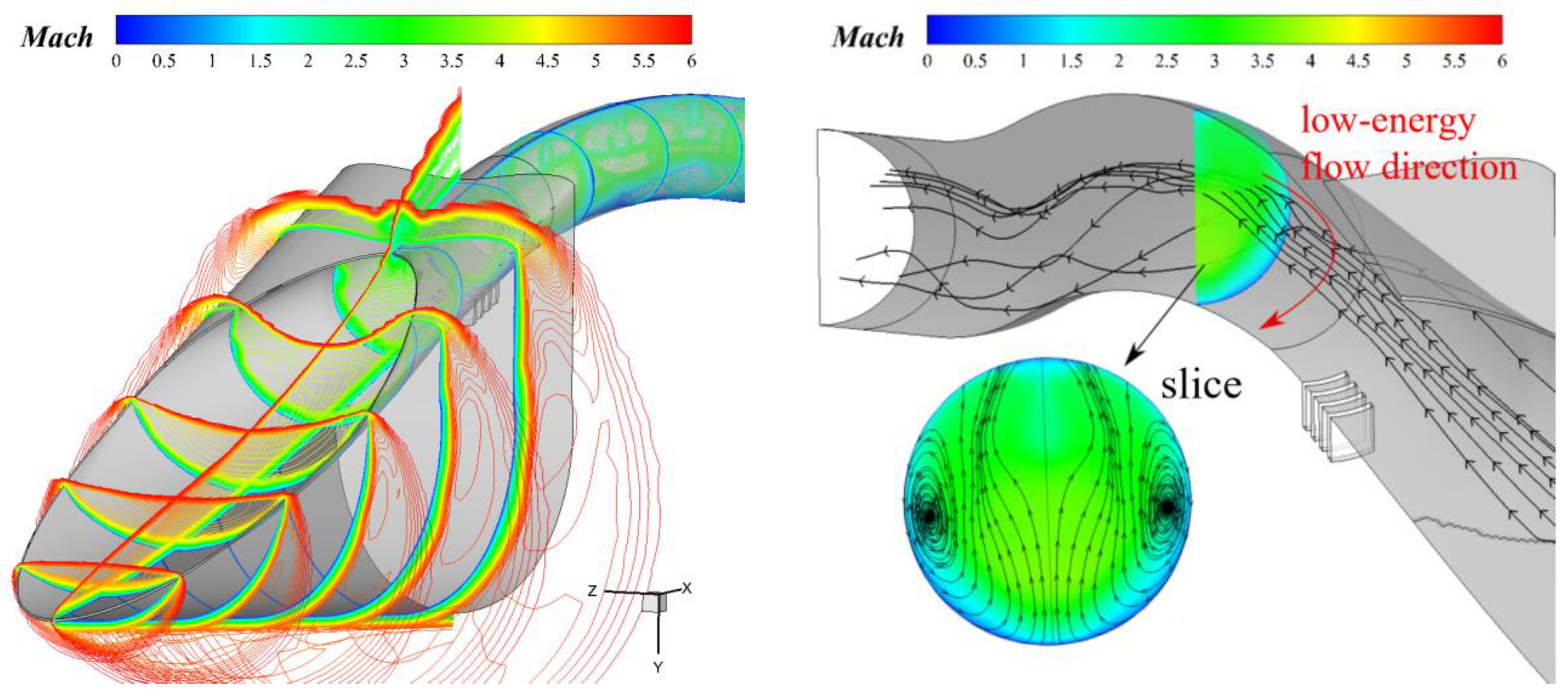
Figure 15 shows the three-dimensional flow field contour and local streamline diagram of the inlet with a forebody at the Mach number of 6. The black arrow lines indicate the flow direction of the streamlines, and the red arrows represent the direction of low-energy flow within the slice. It can be seen that at the design point, the external shock on the lip is nearly, the inlet starts normally, and there is no obvious flow separation in the internal flow path. Unlike the conventional two-dimensional or axisymmetric inlet flow field, there are obvious vortex structures in the internal flow path induced by the cowl shock. Due to the shock wave, pressure near the cowl side is higher, while pressure near the compression surface is lower due to the expansion wave. Therefore, a pressure gradient between the two surfaces is generated. Driven by the pressure gradient, the air flow near the cowl side is washed to the other side, resulting in a secondary flow along the axial direction. In the process of downstream development, a streamwise vortex gradually formed. This is the reason for the uneven thickness of the boundary layer.

4.3.2. Performance Comparison of Inlet with and Without Forebody on Design Point

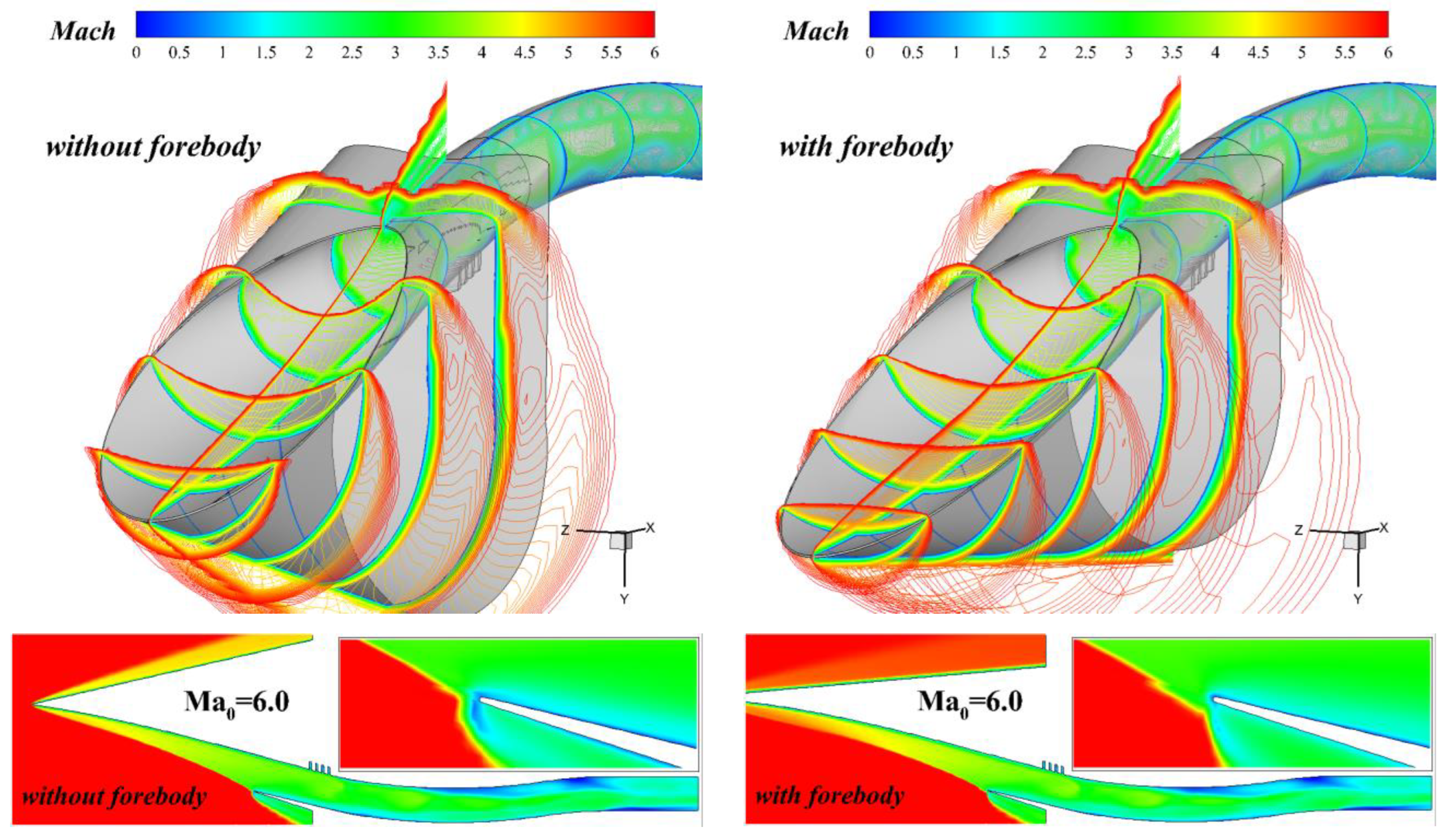
Figure 16 shows the Mach number contour on the symmetrical plane and flow field slices of the inlet, in which the left is the original inlet configuration without a forebody, and the right is the optimized configuration after adding a forebody. As shown in the figure, the inward-turning inlet without a forebody decelerates and pressurizes the incoming flow through a three-dimensional curved shock wave at the leading edge. In design condition, the curved shock waves attached to the cowl lip and the inlet start normally. The flow coefficient of the inlet is 0.98, and the total pressure recovery coefficient at the outlet is 0.30. After matching the forebody, from the spanwise slice diagram, it is found that the forebody has better internal waverider characteristics and less transverse overflow; however, from the contour map of the symmetrical plane, the leading-edge curved shock wave fails to terminate at the inlet lip, supersonic overflow occurs at the lip, and the flow coefficient is reduced to 0.96. In addition, due to the pre-compression of the forebody, the initial turning angle of the inflow decreases, and the total pressure loss of the inlet with the forebody is lower than that without the forebody, so the total pressure recovery coefficient at the outlet is increased to 0.33.
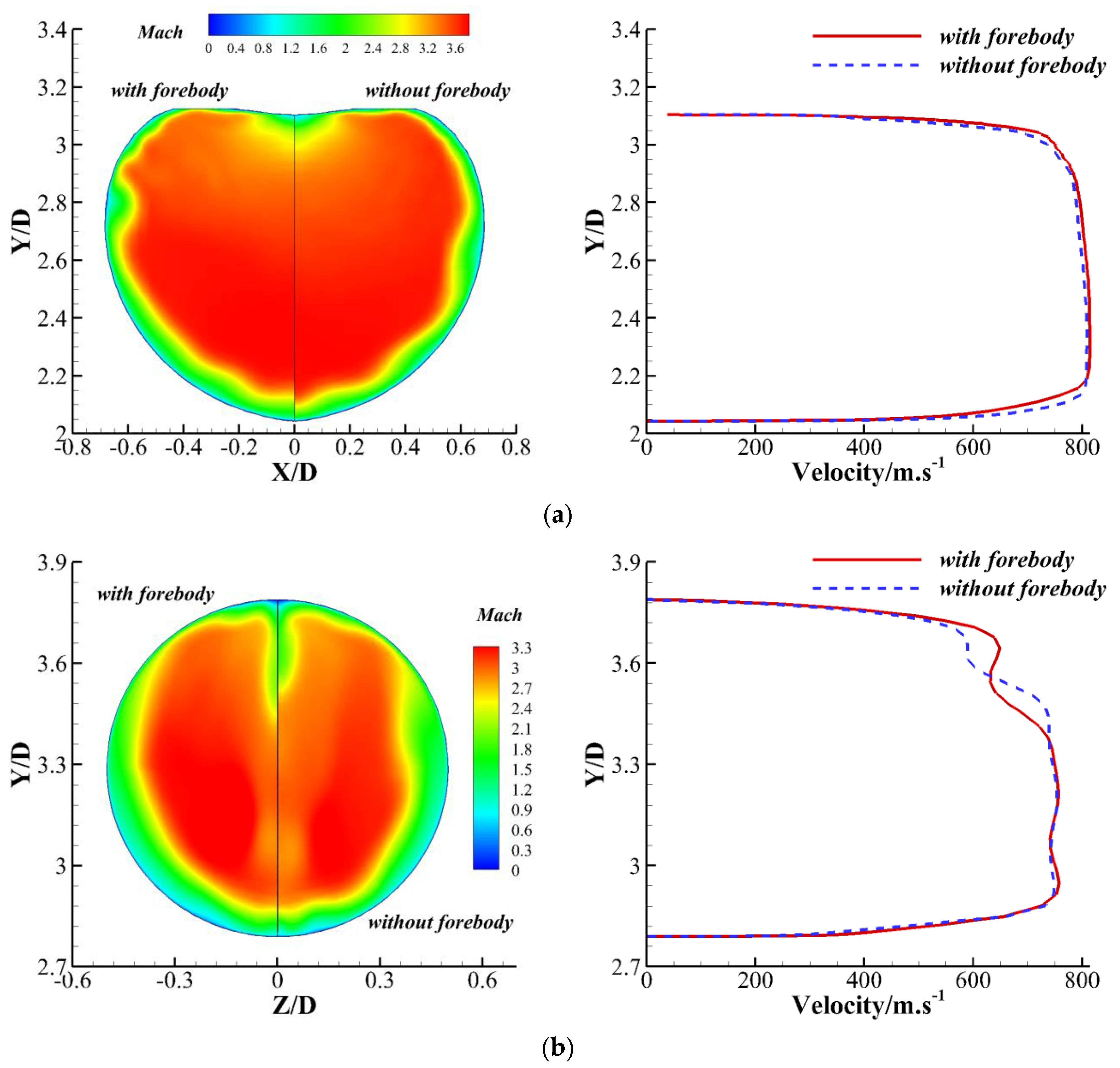
Figure 17 shows the Mach contours and velocity profile of the inlet and throat sections for two configurations, where (a) represents the entrance section, and (b) represents the throat section. As shown in the figure, at the entrance section, the Mach number distribution and velocity profiles of the two configurations are similar. Compared to the configuration without a forebody, the external pressure section of the inlet becomes longer after adding the forebody, and the boundary layer develops more fully; therefore, the boundary layer on the compression surface will be thicker. As the boundary layer continues to develop downstream in the path, suction slots at the inlet shoulder weaken the development difference of the boundary layer in the two configurations, so that the velocity profile on one side of the compression surface is approximately the same. On the cowl side, the boundary layer development in the two configurations differs significantly due to the different incident positions of the three-dimensional curved shock wave, so the velocity profile on the lip side is also quite different.
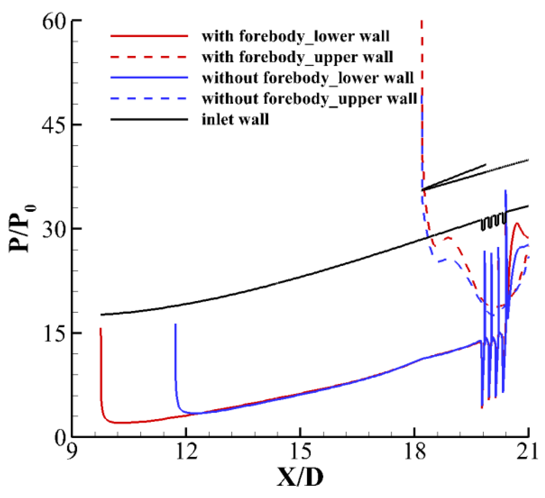
Figure 18 shows the pressure distribution along the upper and lower walls of the two inlet configurations, in which the red curve represents the inlet with a forebody and the blue curve represents the inlet without a forebody. From the pressure distribution, it can be seen that for the inlet studied in this paper, the forebody has little influence on the external pressure segment of the inlet, but it has an obvious influence on the cowl side of the internal pressure segment. This is mainly because after matching the forebody, the loss of the external pressure segment of the inlet is reduced, the inlet Mach number is higher, and the intensity of the reflected shock wave from the lip is stronger, so the pressure distribution on the cowl side of the inlet with the forebody is also higher.

4.3.3. Analysis of Velocity Characteristics and Angle of Attack Characteristics of Inlet with and Without Forebody

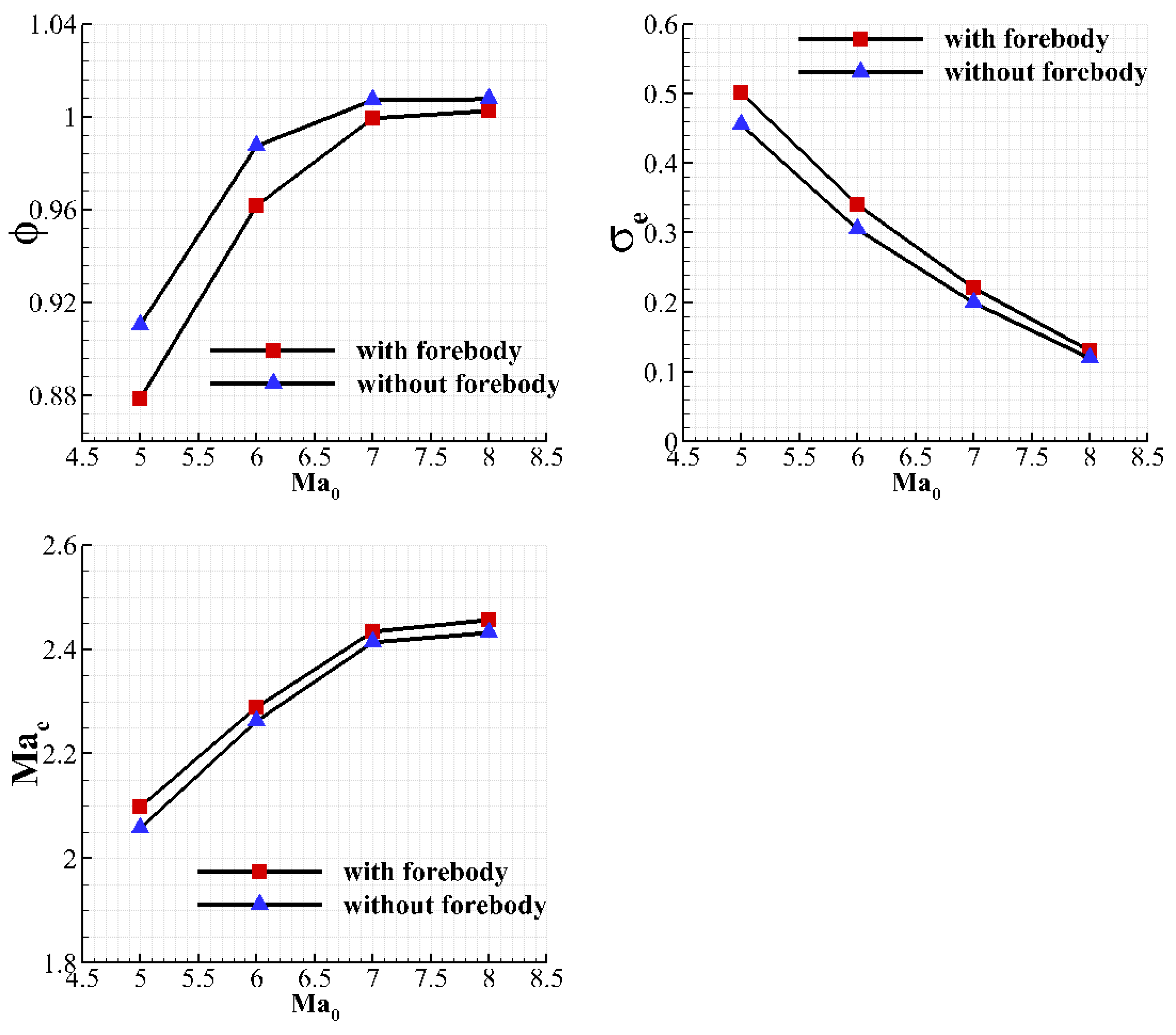
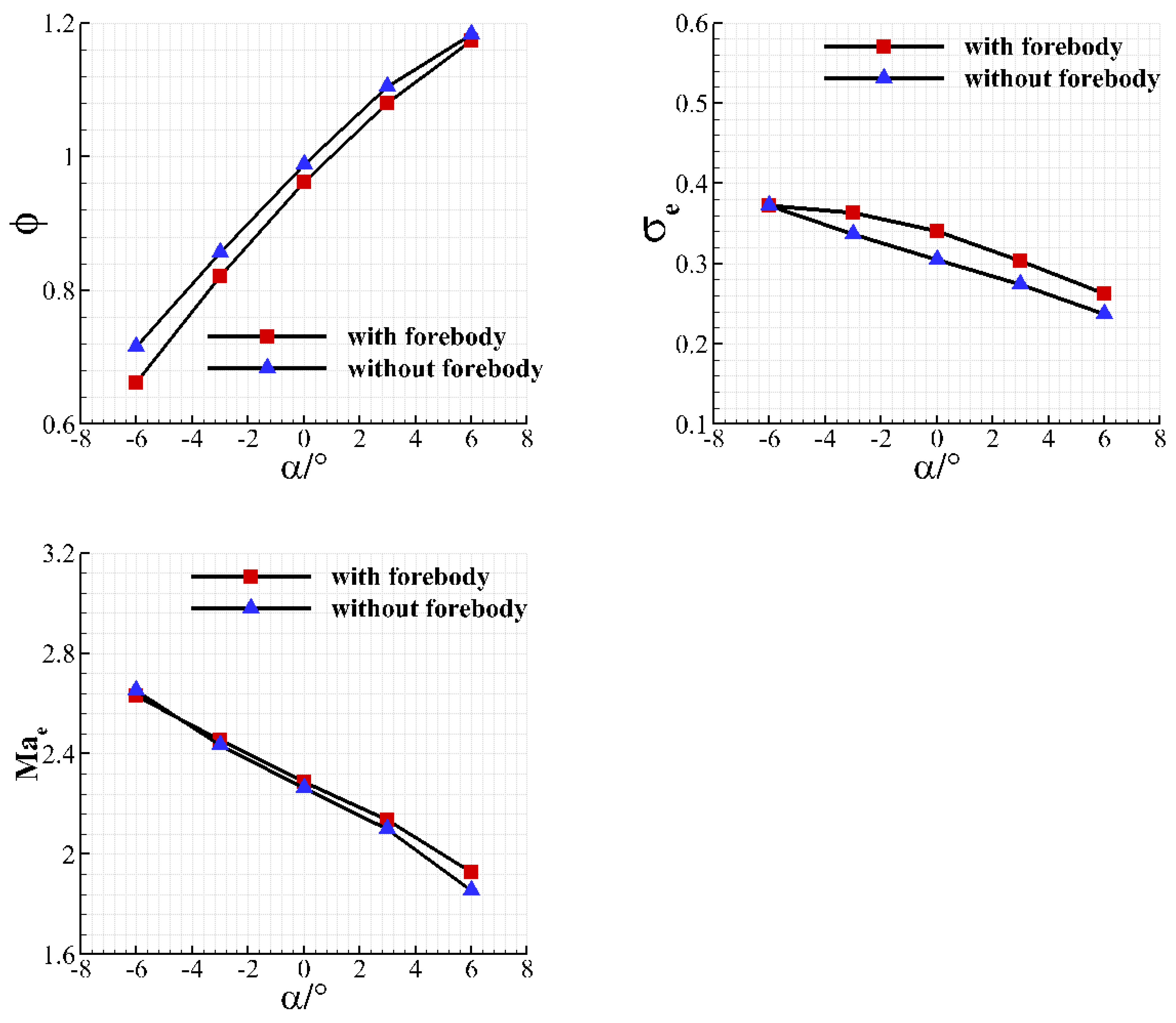
Figure 19 and Figure 20 show the variation trend of the outlet performance for the two inlet configurations at different incoming Mach numbers and angles of attack. The abscissa represents the incoming flow Mach number and the incoming flow angle of attack, respectively, and the ordinate represents the flow coefficient, total pressure recovery coefficient, and Mach number of the inlet and outlet, respectively. It can be seen from the figure that the velocity characteristics and angle of attack characteristics of the two configurations are similar. With the increase of the incoming Mach number and the incoming angle of attack, the total pressure recovery coefficient of the inlet and outlet decreases, and the outlet Mach number increases. Compared to the configuration without a forebody, the configuration with a forebody has a weaker compression effect on the airflow. Therefore, the total pressure recovery coefficient at the outlet is higher, and the outlet Mach number is also higher. In practical applications, whether to add a forebody depends on the index requirements of the inlet and outlet. In addition, the forebody design method in this paper is only a waverider-like forebody design method. The designed forebody does not fully achieve shock wave closure, thus causing certain flow loss. The full capture of flow can be realized by optimizing the forebody profile theory.
Based on the comprehensive discussion of the comparison of simulation results in the previous subsections, we find that the configurations with and without a forebody have very similar flow field structures under the design condition, and their flow rates and cross-sectional statistical performances are similar. However, the flow rate of the configuration with a forebody is slightly lower, while the Mach number and total pressure are slightly higher. This is also the case in most off-design operating conditions. The loss of flow rate indicates that there is still a small room for optimization in the design of the forebody. The slight increase in Mach number and total pressure suggests that the overall compression capacity of the inlet for the airflow is weakened after adding the forebody, which may be closely related to the reduction in the intensity of the external compression wave system.

5. Discussion

This paper proposes a forebody integration method for inward-turning inlets. This method achieves integration by configuring a forebody with aerodynamic and geometric matching for a given inward-turning inlet. It uses the method of characteristics to realize the inverse design of the forebody profile with a controllable shock wave shape. Then, boundary layer correction and design adjustments based on numerical simulation results are carried out on the two-dimensional profile, and finally, the forebody is generated and matched to the given inward-turning inlet.
To verify the effectiveness of this design method and understand the impact on inlet performance after the forebody is configured, experimental studies and numerical simulations are conducted on the inlet with the forebody. The experimental results are in good agreement with those obtained from numerical simulations, which proves the effectiveness of the numerical research method. Both experimental and simulation results show that after the forebody is configured, the inlet mass flow rate in the design state decreases by only 2% and achieves a shock on the lip. This indicates that the forebody configuration scheme proposed in this paper for the circular-capture inward-turning inlet can well realize the aerodynamic and geometric matching between the inlet and the forebody, with a high degree of integration and good internal waveriding characteristics.
In addition, it is found that after the forebody is configured, the overall compression effect of the inlet on the airflow is weakened, and both the outlet Mach number and total pressure increase slightly. This may be caused by the extension of the external compression section, which reduces the shock wave intensity in the external compression section, and this point deserves the attention of engineering designers.

Author Contributions

Conceptualization, J.L., T.G. and H.Y.; Methodology, D.Y.; Software, D.Y.; Validation, T.G.; Formal analysis, D.Y.; Investigation, J.L. and T.G.; Resources, J.L.; Data curation, D.Y.; Writing—original draft, D.Y.; Writing—review and editing, D.Y.; Visualization, D.Y. and J.L.; Supervision, J.L. and H.Y.; Project administration, J.L., T.G. and H.Y.; Funding acquisition, J.L. and H.Y. All authors have read and agreed to the published version of the manuscript.

Funding

This work is funded by the National Key Laboratory of Ramjet (No.2023-JCJQ-LB-018-07).

Data Availability Statement

The dataset is available upon request from the authors.

Conflicts of Interest

The authors declare no conflicts of interest.

References

  1. Smart, M.K. Experimental testing of a hypersonic inlet with rectangular-to-elliptical shape transition. J. Propuls. Power 1999, 17, 276–283. [Google Scholar] [CrossRef]
  2. Ren, H.; Yuan, H.; Zhang, J.; Zhang, B. Experimental and numerical investigation of isolator in three-dimensional inward turning inlet. Aerosp. Sci. Technol. 2019, 95, 105435. [Google Scholar] [CrossRef]
  3. Lewis, M. A Hypersonic Propulsion Airframe Integration Overview. In Proceedings of the 39th AIAA/ASME/SAE/ASEE Joint Propulsion Conference and Exhibit, Huntsville, AL, USA, 20–23 July 2003. [Google Scholar]
  4. Xiang, X.; Qian, Z. An Overview and Development Analysis of Air-Breathing Hypersonic Airframe/Propulsion Integrative Design Technology. Tuijin Jishu/J. Propuls. Technol. 2018, 39, 2207–2218. (In Chinese) [Google Scholar]
  5. Kothari, A.P. Designs of and Methodology for Inward or Outward, and Partially Inward or Outward Turning Flow Hypersonic Air-Breathing and Rocket-Based- Combined- Cycle Vehicles. U.S. Patent 6164596A, 26 December 2000. [Google Scholar]
  6. Li, Y.; You, Y.; Han, W.; Teng, J. An Innovative Integration Concept for Forebody and Two-Dimensional Hypersonic Inlet with Controllable Wall Pressure Distribution. In Proceedings of the 20th AIAA International Space Planes and Hypersonic Systems and Technologies Conference, Glasgow, Scotland, 6–9 July 2015. [Google Scholar]
  7. Qiao, W.; Yu, A.; Yang, D.; Le, J. Integration design of inward-turning inlets based on forebody shock wave. Acta Aeronaut. Astronaut. Sin. 2018, 39, 65–76. (In Chinese) [Google Scholar]
  8. Nonweiler, T. Aerodynamic Problems of Manned Space Vehicles. J. R. Aeronaut. Soc. 1959, 63, 521–528. [Google Scholar] [CrossRef]
  9. Nonweiler, T. Delta Wing of Shape Amenable to Exact Shock-Wave Theory. J. R. Aeronaut. Soc. 1963, 67, 39–40. [Google Scholar] [CrossRef]
  10. Rasmussen, M.L.; Jischke, M.C.; Daniel, D.C. Experimental Forces and Moments on Cone-Derived Waveriders for M = 3 to 5. J. Spacecr. Rocket. 1982, 19, 592–598. [Google Scholar] [CrossRef]
  11. Sobieczky, H.; Zores, B.; Wang, Z.; Qian, Y.J. High speed flow design using the theory of osculating cone and axisymmetric flows. Chin. J. Aeronaut. 1999, 12, 3–10. [Google Scholar]
  12. He, X.; Ni, H. Osculating inward turning cone (OIC) wave rider-design methods and performace analysis. Chin. J. Theor. Appl. Mech. 2011, 43, 803–808. (In Chinese) [Google Scholar]
  13. Starkey, R.; Lewis, M. Design of an engine-airframe integrated hypersonic missile within fixed box constraints. In Proceedings of the 37th Aerospace Sciences Meeting & Exhibit, Reno, NV, USA, 11–14 January 1999. [Google Scholar]
  14. Zucrow, M.J.; Hoffman, J.D. Gas Dynamics; John Wiley & Sons, Inc.: New York, NY, USA, 1976; pp. 191–192. [Google Scholar]
  15. Li, Y.; Zhang, K.; Nan, X. Design of hypersonic inward turning inlets base on concept of controllable Mach number distribution. J. Aerosp. Power 2012, 27, 2484–2491. (In Chinese) [Google Scholar]
  16. Nan, X.; Zhang, K.; Jin, Z. Investigation on hypersonic inward turning inlets with controlled pressure gradient. J. Aerosp. Power 2011, 26, 518–523. (In Chinese) [Google Scholar]
  17. Qian, Y. Computer program of supersonic axisymmetric rotaional characteristic method. J. Beijing Univ. Aeronaut. Astronaut. 1996, 4, 70–75. (In Chinese) [Google Scholar]
  18. Qiao, W.; Huang, G.; Xia, C.; Wang, M. Development of inverse characteristic method for matching design of high-speed aircraft forebody/inlet. J. Aerosp. Power. 2014, 29, 1444–1452. (In Chinese) [Google Scholar]
  19. Guo, S.; Wang, Z.; Zhao, Y. Inverse Design of the Fore-body Curved Shock Wave of the Hypersonic Planar Inlet. Acta Aeronaut. Astronaut. Sin. 2014, 35, 1246–1256. (In Chinese) [Google Scholar]
  20. Han, W.; Zhu, C.; You, Y.; Li, Y. An inverse method for supersonic flowfield with given downstream boundary. Acta Aeronaut. Astronaut. Sin. 2016, 37, 624–631. (In Chinese) [Google Scholar]
  21. Yuan, H.; Li, Z.; Zhang, J.; Wang, X. Experimental and Numerical Research on a Three-Dimensional Inward-Turning Inlet. J. Aerosp. Eng. 2023, 36, 04023008. [Google Scholar] [CrossRef]
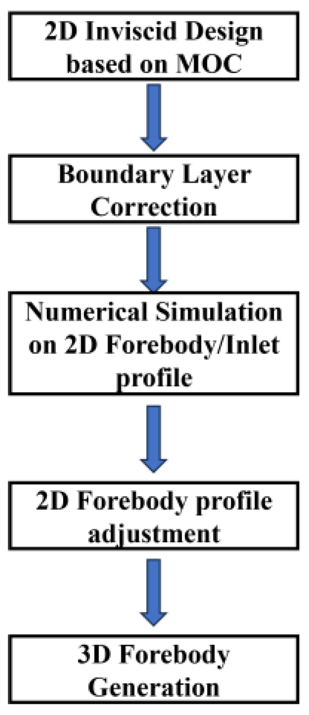
Figure 1. Forebody design and matching process.
Aerospace 12 00763 g001
Figure 2. Schematic Diagram for the Solution of the Inverse Design Wall Boundary with a Known Curved Shock Wave: (a) Single-point solution, (b) Full flow field space-marching solution.
Aerospace 12 00763 g002
Figure 3. Comparison of MOC and CFD Results: (a) Flow field comparison, and (b) Pressure comparison.
Aerospace 12 00763 g003
Figure 4. Comparison of Boundary Layer Correction Results: (a) Uncorrected, (b) corrected.
Aerospace 12 00763 g004
Figure 5. Matching diagram of inlet and curved-wall forebody on symmetrical plane: (a) Geometric matching, and (b) Aerodynamic matching.
Aerospace 12 00763 g005
Figure 6. Forebody generation scheme: (a) Case 1, (b) Case 2.
Aerospace 12 00763 g006
Figure 7. Configuration of the inlet with and without forebody.
Aerospace 12 00763 g007
Figure 8. The geometric configuration and experimental model of the inlet with or without a forebody.
Aerospace 12 00763 g008
Figure 9. NHW wind tunnel.
Aerospace 12 00763 g009
Figure 10. Distribution of Static Pressure Dynamic Measuring Points along Inlet [21].
Aerospace 12 00763 g010
Figure 11. Boundary conditions and the structured grid of the inlet.
Aerospace 12 00763 g011
Figure 12. Pressure Distribution along Lower Wall of Inlet (Ma = 6.0, α = 0°): (a) without forebody, (b) with forebody.
Aerospace 12 00763 g012
Figure 13. Total pressure recovery coefficient contour of inlet with and without forebody (Ma = 6.0, α = 0°): (a) without forebody, (b) with forebody.
Aerospace 12 00763 g013
Figure 14. Simulation and experimental comparison of pressure along the inlet’s upper and lower wall surfaces (with or without forebody).
Aerospace 12 00763 g014
Figure 15. Flow field slice and local streamline of the inlet under the design state [21].
Aerospace 12 00763 g015
Figure 16. Flow field slices and Mach contours on the symmetry plane of the inlet with and without the forebody.
Aerospace 12 00763 g016
Figure 17. Mach contours and velocity profiles of entrance and throat sections with and without a forebody: (a) Inlet port, (b) Inlet throat.
Aerospace 12 00763 g017
Figure 18. Pressure distribution along the wall with and without the forebody.
Aerospace 12 00763 g018
Figure 19. Variation of outlet performance of the inlet with and without a forebody at different inflow Mach numbers.
Aerospace 12 00763 g019
Figure 20. Variation of outlet performance of the inlet with and without a forebody under different angles of attack.
Aerospace 12 00763 g020
Table 1. NHW wind tunnel incoming flow conditions.
Ma0P*/MPaT*/KP/Pa
50.6440380
60.63501134
P* denotes the total pressure, T* denotes the total temperature.
Table 2. Numerical simulation and wind tunnel test verification of inlet and outlet performance (with or without forebody).
With ForebodyWithout Forebody
σπMaeσπMae
EXP0.3137.802.320.2933.732.35
CFD0.3336.562.290.3034.632.26
error6.45%3.28%1.29%3.45%2.67%3.83%
Disclaimer/Publisher’s Note: The statements, opinions and data contained in all publications are solely those of the individual author(s) and contributor(s) and not of MDPI and/or the editor(s). MDPI and/or the editor(s) disclaim responsibility for any injury to people or property resulting from any ideas, methods, instructions or products referred to in the content.