Article

Multi-Agent Reinforcement Symbolic Regression for the Fatigue Life Prediction of Aircraft Landing Gear

1
Department of Aeronautics and Astronautics, Fudan University, Shanghai 200433, China
2
AECC Hunan Power Machinery Research Institute, Zhuzhou 412002, China
3
Institute of Space Internet, Fudan University, Shanghai 200433, China
*
Author to whom correspondence should be addressed.
Aerospace 2025, 12(8), 718; https://doi.org/10.3390/aerospace12080718
Submission received: 5 July 2025 / Revised: 9 August 2025 / Accepted: 11 August 2025 / Published: 12 August 2025

Abstract

Accurate fatigue life prediction of aircraft landing gear is crucial for ensuring flight safety and preventing catastrophic structural failures. However, traditional empirical methods face significant limitations in capturing complex multiaxial loading conditions, while machine learning approaches suffer from lack of interpretability in critical safety applications. To address the dual challenges of prediction accuracy and model interpretability, a multi-agent reinforced symbolic regression (MA-RSR) framework is proposed by integrating multi-agent reinforcement learning with symbolic regression (SR) techniques. Specifically, MA-RSR employs a collaborative mechanism that decomposes complex mathematical expressions into parallel components constructed by independent agents, effectively addressing the search space explosion problem in traditional SR. The system incorporates Transformer-based architecture to enhance symbolic selection capabilities, while an intelligent masking mechanism ensures mathematical rationality through multi-level constraints. To demonstrate effectiveness of the proposed method, validation is conducted using SAE4340 steel multiaxial fatigue data and landing gear finite element simulation. The MA-RSR framework successfully discovers two mathematical expressions achieving R2 of 0.96. Compared to traditional empirical formulas, MA-RSR achieves prediction accuracy improvements exceeding 50% while providing complete interpretability that machine learning methods lack. Furthermore, the multi-agent collaborative mechanism significantly enhances search efficiency through parallel expression construction compared to existing symbolic regression approaches.

1. Introduction

As the critical load-bearing system of aircraft, landing gear directly affects flight safety and overall aircraft reliability. During service operation, landing gear operates under harsh working conditions and bears complex multi-axial loads. Therefore, accurate prediction of its fatigue life is extremely challenging [1,2,3]. The development of accurate and effective methods for landing gear fatigue life prediction has emerged as a key research focus in both academia and industry [4]. Current research focuses on accurately characterizing the intrinsic relationship between mechanical properties (such as tensile strength and ductility) and fatigue characteristics of landing gear materials to enable scientific assessment of material and structural durability.
The development of fatigue life prediction theory has evolved from simple to complex approaches, moving from single methods to combined approaches. Within the elastic strain theoretical framework, Basquin et al. [5] established a power function relationship between stress amplitude and fatigue life based on extensive experimental observations. This work marked the beginning of quantitative fatigue research. In the plastic strain framework, Coffin and Manson et al. [6,7] independently revealed the relationship between plastic strain amplitude and fatigue life from the perspective of material plastic deformation, significantly advancing low-cycle fatigue theory. However, elastic or plastic mechanisms alone cannot completely explain material fatigue behavior. To solve this limitation, Morrow et al. [8] creatively combined elastic and plastic mechanisms to create a unified model for better fatigue life prediction. Despite these important theoretical advances, real engineering structures rarely exist under uniaxial stress states, particularly critical components like landing gear [9]. Findley et al. [10] acutely recognized this issue and first proposed the need to evaluate damage on specific planes, establishing criteria that consider the combined effects of shear and normal stresses. This introduction of the critical plane concept was revolutionary, fundamentally changing the research paradigm for multiaxial fatigue. Based on critical plane theory, Brown and Miller et al. [11] discovered through extensive experimental observations that fatigue cracks tend to initiate on the maximum shear strain plane, leading to the development of strain-based critical plane methods that more accurately reflect the physical processes of crack initiation and propagation. To further improve prediction accuracy, Fatemi and Socie et al. [12] innovatively introduced correction terms considering non-proportional hardening effects while maintaining the physical foundation of critical plane methods, achieving a balance between accuracy and practicality. As research progressed, it was found that complex structural components like landing gear often exhibit coexisting multiple crack modes. To address this challenge, Wu et al. [13] successfully captured damage evolution laws under mixed-mode conditions by comprehensively considering interactions among shear strain, normal stress, and normal strain, incorporating correction coefficients related to material yield characteristics. Despite these advances, traditional methods still face fundamental limitations when applied to landing gear fatigue analysis: first, their foundation on specific assumptions and simplifications makes it difficult to comprehensively describe complex load spectra; second, material parameter determination requires extensive specialized experiments, making the process costly and time-consuming; finally, their fixed mathematical forms limit model adaptability to new operating conditions.
To overcome the deficiencies of traditional methods, data-driven machine learning methods provide new solutions for fatigue life prediction. These approaches can effectively capture the intrinsic relationships between mechanical performance parameters and fatigue life without establishing explicit mathematical models. This capability significantly improves the performance evaluation accuracy of aerospace structures [14]. Sun et al. [15] proposed an exponential distribution optimizer-based integrated surrogate model, which achieved a 63.17% improvement in modeling accuracy for high cycle fatigue life prediction of helicopter flanges. Zhang et al. [16] constructed two fatigue life prediction models based on gradient boosting (GB) and random forest (RF) algorithms to predict ultra-high-cycle fatigue life using GCr15 bearing steel data obtained from fatigue tests. The results demonstrated that the GB model achieved a mean square error (MSE) of 0.69. Heng et al. [17] developed a multiaxial fatigue life prediction model based on a convolutional neural network-long short-term memory hybrid neural network. The model demonstrated excellent performance in validation tests using six different metallic materials, with prediction accuracy maintained within a 1.3-fold error range and good extrapolation capability. Farhadi et al. [18] systematically compared various ensemble learning methods, including extreme gradient boosting (XGBoost), RF, stacking, and ensemble neural networks, for predicting the fatigue life of notched metallic materials. The results demonstrated that ensemble neural networks combined with incremental energy release rate exhibited optimal performance in fatigue life prediction for notched metallic components. Liao et al. [19] established a physics-informed machine learning framework specifically for notched fatigue assessment of aerospace alloys, which achieved excellent predictive performance under limited sample conditions by integrating traditional fatigue theory with deep neural networks. The prediction results showed a coefficient of determination R-square (R2) > 0.95, providing an effective tool for notched fatigue assessment under complex loading conditions. Although machine learning methods have significant advantages in predicting complex relationships between mechanical performance parameters and fatigue life, the performance heavily depends on sufficient training datasets, and the internal decision-making process of models lacks transparency. Furthermore, the models mentioned above cannot provide clear explanations of physical correlations between parameters, and the lack of physical interpretability limits widespread application in complex engineering environments.
Recent studies have shown that symbolic regression (SR) effectively addresses the problems of insufficient accuracy in traditional empirical formulas, while overcoming the limitation of lacking interpretability in machine learning methods [20]. SR can automatically discover mathematical expressions that describe given datasets, which improves prediction accuracy while avoiding the “black box” problem. Recent studies have demonstrated that SR applications in fatigue life prediction have achieved significant progress. Zhang et al. [21] developed a symbolic regression-neural network fusion framework, which achieved MSE reductions of 55.4% and 45% compared to RF and support vector machine (SVM) models, respectively, in multiaxial fatigue life prediction. Cao et al. [22] compared SR methods based on genetic programming and multi-population evolution algorithms and validated their advantages in prediction accuracy and model interpretability through comprehensive evaluation of 82 types of steel. Feng et al. [23] employed SR as an auxiliary tool for artificial neural network (ANN) to establish prediction models for T91 steel and 316L stainless steel in lead-bismuth eutectic corrosion environments, achieving a 22% reduction in root mean square error (RMSE) and improving prediction accuracy. Ding et al. [24] combined neighborhood component analysis feature extraction with SR, achieving significant accuracy improvements in real flight tests of conventional layout unmanned aerial vehicle and X-configuration aircraft. Given the technical challenges of traditional SR in search efficiency, reinforcement learning provides a new breakthrough in optimization strategies for symbolic search. Li et al. [25] recently proposed a reinforced symbolic learning (RSL) framework that combines symbolic regression with deep reinforcement learning, incorporating logical constraints to ensure physically meaningful expressions while using recurrent neural network (RNN)-guided optimization. However, existing RL-based SR approaches typically employ single-agent frameworks that struggle with search space explosion in complex engineering problems and rely on sequential expression construction processes. These research findings fully demonstrate the tremendous potential of SR in understanding model behavior, adhering to physical principles, and making concise predictions. However, traditional SR still faces a technical challenge of low search efficiency, particularly when dealing with complex multiaxial fatigue problems such as landing gear. The exponential growth of search space makes it difficult for traditional methods, like genetic programming, to find optimal solutions within a reasonable time.
Given the technical challenges of traditional SR in search efficiency, reinforcement learning provides a new breakthrough in optimization strategies for symbolic search. Through intelligent search strategies and dynamic policy adjustment, reinforcement learning can significantly improve the performance deficiencies of traditional SR. Based on this technical integration approach, this study proposes a multi-agent reinforced symbolic regression (MA-RSR) framework that combines multi-agent reinforcement learning with SR to achieve automatic discovery and optimization of complex mathematical expressions through collaborative learning mechanisms. Taking SAE4340 steel landing gear as the research object, the effectiveness of the MA-RSR method in fatigue life prediction is validated, providing new technical support for fatigue life research of critical aviation components. The main contributions of this paper are as follows:
(1)
A multi-agent collaborative mechanism is proposed that decomposes complex expressions into multiple basic components for parallel learning, improving search efficiency and solving the search space explosion and convergence difficulties faced by traditional SR.
(2)
A MA-RSR framework is developed that combines SR with Transformer-based reinforcement learning to achieve highly interpretable fatigue life prediction, overcoming the “black box” limitations of machine learning methods.
(3)
An intelligent masking mechanism is designed that ensures the mathematical rationality and physical significance of generated expressions through multi-level constraints, avoiding the generation of invalid expressions and improving model reliability.
(4)
Based on SAE4340 steel multiaxial fatigue experimental data and landing gear engineering validation, the prediction accuracy and practicality of the MA-RSR method are demonstrated, providing an effective tool for fatigue life assessment of complex engineering structures.
The remainder of this paper is outlined as follows. Section 2 reviews the development trajectory of typical fatigue life prediction empirical formulas and the fundamental theory of SR. Section 3 details how to construct the complete technical architecture of the MA-RSR method. Section 4 validates the prediction performance of the MA-RSR method through numerical simulation. Section 5 constructs a finite element model of landing gear to verify the practicality of this method in complex engineering structures. The conclusions of this paper are summarized in Section 6.

2. Theoretical Foundation

2.1. Traditional Empirical Methods

Accurate prediction of landing gear fatigue life is a critical component in ensuring the safe and reliable operation of aircraft. Traditional empirical methods provide important theoretical guidance in characterizing the intrinsic relationship between material mechanical properties and fatigue life. These formulas are based on extensive experimental observations and theoretical analyses, establishing a solid foundation for fatigue life prediction. The following are classical fatigue life prediction formulas.

2.1.1. Coffin–Manson Criterion

In the field of material fatigue life prediction, the Coffin–Manson criterion [6,7,26] is widely used to describe the relationship between plastic strain and fatigue life under low cycle fatigue conditions and is particularly applicable to situations where large plastic strains are generated under cyclic loading. For critical components, such as landing gear that bear complex multiaxial loads, the expression of the Coffin–Manson criterion can be written in the following form:
ε a = σ f E ( 2 N f ) b + ε f ( 2 N f ) c
γ a = τ f G ( 2 N f ) b 0 + γ f ( 2 N f ) c 0
where εɑ and γɑ respectively represent the axial and shear strain amplitudes; Nf is the fatigue life; E is the Young’s modulus; G is the shear modulus; σ′f is the fatigue strength coefficient; ε′f is the fatigue ductility coefficient; b represents the fatigue strength exponent; c represents the fatigue ductility exponent; τ′f represents the fatigue shear strength coefficient; γ′f represents the fatigue shear ductility coefficient; b0 represents the fatigue shear strength exponent; c0 is the fatigue shear ductility exponent. The numerical values of these parameters are determined by material type and working environment.

2.1.2. Kandil–Brown–Miller (KBM) Criterion

The KBM criterion is an improvement of the Brown–Miller criterion, which considers the influence of normal stress on fatigue damage, and the formula is written in the following form:
Δ γ max 2 + S Δ ε n = ( 1 + ν e + ( 1 ν e ) S ) σ f E ( 2 N f ) b + ( 1 + ν p + ( 1 ν p ) S ) ε f ( 2 N f ) c
where Δγmax/2 represents the maximum shear strain amplitude; Δεn represents the normal strain range on the maximum shear plane; νe and νp represent the elastic Poisson’s ratio and plastic Poisson’s ratio; S is a material constant obtained by fitting uniaxial and torsional fatigue data that represents the influence of normal strain on crack propagation. In this case, S = 0.2 is used for computational simplification.

2.1.3. Fatemi–Socie (FS) Criterion

The FS criterion [12] specifically considers the influence of non-proportional loading, and it is expressed as
Δ γ max 2 1 + k σ n , max σ y = τ f G ( 2 N f ) b 0 + γ f ( 2 N f ) c 0
where the material constant k is obtained by fitting uniaxial fatigue data with pure torsional data to represent the material’s sensitivity to normal stress. σn,max represents the maximum normal stress amplitude, and σy represents the yield strength.

2.1.4. Wu–Hu–Song (WHS) Criterion

The Wu–Hu–Song (WHS) criterion [13] comprehensively considers the coupling effects of shear strain, normal stress, and normal strain:
Δ γ max 2 + k ( σ n , max Δ ε n E ) 0.5 = τ f G ( 2 N f ) b 0 + γ f ( 2 N f ) c 0
Although these traditional empirical formulas possess good predictive capability under specific conditions, inherent limitations still exist when facing the complex service environment of landing gear: the formula forms are fixed and difficult to adapt to new load spectra and material properties; parameter determination requires extensive specialized experiments with high costs; the capability to describe complex multiaxial non-proportional loading paths is limited.

2.2. Fundamentals of SR

SR is an advanced machine learning method that aims to automatically discover explicit mathematical expressions capable of accurately describing the relationships between input and output variables from given datasets [27]. Unlike traditional regression analysis methods, SR does not merely adjust parameters in predefined equations, but rather explores unlimited hypothesis spaces of potential mathematical operation combinations to discover expression forms and parameters that most accurately generalize observed data. The core concept involves representing mathematical expressions as binary trees, where internal nodes represent mathematical operators (such as +, −, *, /, log, etc.) and leaf nodes contain input variables or constants [28]. Through evolutionary algorithms or other optimization strategies, searches are conducted in the expression space to ultimately obtain mathematical models that possess both high predictive accuracy and relatively concise forms.

3. The Proposed Method

This section presents the MA-RSR framework developed for predicting aircraft landing gear fatigue life. Section 3.1 introduces the expression decomposition strategy of the MA-RSR framework. Section 3.2 provides a detailed description of the MA-RSR architecture design. Section 3.3 focuses on the Transformer-based agent design. Section 3.4 introduces the multi-level constraint strategies of the intelligent masking mechanism.

3.1. Expression Decomposition Strategy

The decomposition and construction of complex mathematical expressions are based on the Kolmogorov–Arnold representation theorem. This theorem proves that any multivariate continuous function can be represented as a superposition of finite univariate continuous functions, providing a solid mathematical foundation for multi-agent collaborative construction of complex expressions. In the MA-RSR framework, complex target functions are decomposed into combinations of multiple basic mathematical expressions. Each basic expression is constructed by an independent agent. The final prediction function adopts a predefined combination form:
y ^ = g ( f 1 ( x ) , , f n ( x ) )
where ŷ represents the target function value; fi(x) denotes the basic expression constructed by the i-th agent; and g(·) represents the combination function. The design of this architecture fully considers the physical characteristics of fatigue life prediction problems. Through the organic combination of different types of functions, such as polynomials, exponentials, and logarithms, the complex nonlinear relationships between material performance parameters and fatigue life are respectively captured.

3.2. MA-RSR Framework

Based on the aforementioned theory, MA-RSR significantly improves search efficiency through parallelized expression construction processes. The system designs a collaborative network composed of multiple independent agents, with each agent specifically responsible for constructing a particular basic mathematical expression. In MA-RSR, mathematical expressions are represented using binary tree structures, where internal nodes are operators and leaf nodes are variables or constants. Each agent uses unary operators (such as exponential, logarithm, sin, cos, etc.) as root nodes, and gradually selects binary operators (+, −, *, /) along with input variables and constants to construct complete binary tree structures, ultimately forming corresponding mathematical expressions. This design strategy decomposes complex expressions into multiple relatively simple components, reducing the learning difficulty for individual agents. A simple construction process is illustrated in Figure 1.
Figure 1 illustrates a multi-agent collaborative architecture where each agent constructs a binary tree structure through a state transition mechanism to progressively generate mathematical expressions. The framework demonstrates how multiple agents work in parallel to construct different mathematical components, with each agent specializing in specific expression types (exponential, logarithmic, square root, and linear terms). The state transition mechanism shows how the agent progressively builds expressions through sequential symbol selection. Taking Agentn in the last row of the figure as an example, the state transition process operates as follows: starting from the initial empty state0, the agent sequentially selects the operator “+” to form state1 = [+], then selects variable x2 to obtain state2 = [+, x2]. It continues by selecting “/” and constant 3, and finally, it selects the sqrt function, forming the final state5 = [/, 3, x0]. It should be noted that each state maintains only a fixed representation space of 3 symbol positions, while the corresponding tree structure can continuously grow to accommodate the complete expression hierarchy. When the state space becomes filled with new symbols, the system encodes and integrates the current state information into the continuously expanding tree structure. Tree0 contains only the root node “+”, tree1 expands to include “+” and its left child node x2, continuing until tree5 forms a complete ternary addition subtree, with t ree5 ultimately using sqrt as the new root node to encapsulate the entire addition subtree. This design enables the limited state representation space to support the construction of tree structures of arbitrary complexity. The system combines these symbols according to the binary tree structure to generate the mathematical expression sqrt (x2 + x0/3). The entire process achieves effective conversion from linear symbol sequences to hierarchical mathematical expressions.

3.3. Transformer-Based Agent Design

SR expressions are sequence structures containing complex dependency relationships that exist both between locally adjacent elements and in global semantic associations. The Transformer architecture utilizes self-attention mechanisms to model dependency relationships between arbitrary positions in sequences and captures multi-level feature representations through multi-head attention mechanisms.
Individual agents input the current symbolic sequence state into the Transformer encoder, which converts discrete symbols into continuous vector representations through positional encoding and word embedding. As illustrated in Figure 2a, multi-layer self-attention mechanisms analyze dependency relationships and semantic associations between symbols. The contextual representations output by the encoder are mapped to symbol probability distributions through fully connected layers, and agents sample and select the next mathematical symbol according to this distribution to achieve state transitions. Figure 2b demonstrates the complete internal structure of the Transformer encoder and its processing workflow. Figure 2c illustrates an example of the final mathematical expression generated through the Transformer-guided symbolic selection process.
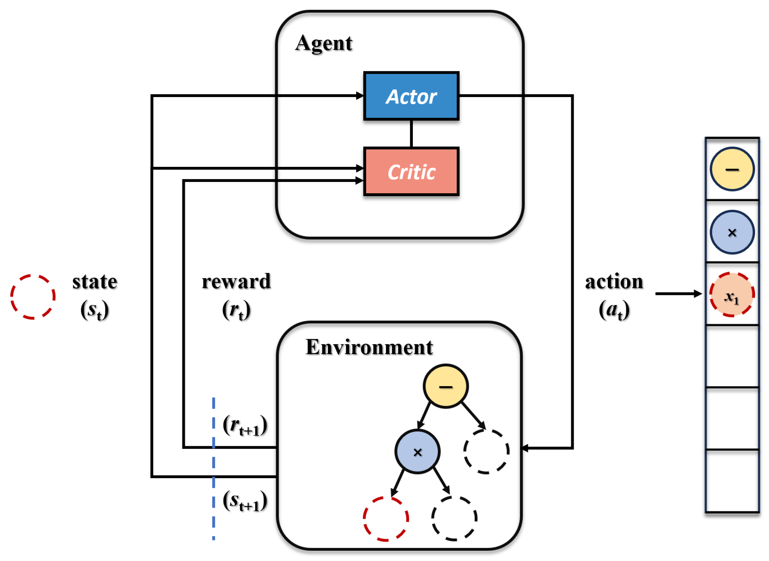
The MA-RSR framework is designed based on the Actor–Critic reinforcement learning architecture. Within the Actor network, multiple Transformer agents operate in parallel, with each agent specializing in constructing specific types of expression components. Although the agents share the same network structure, they maintain independent parameter spaces to achieve synchronized symbol selection and expression construction. The Critic network is responsible for state value evaluation, providing unified learning signals for the entire multi-agent system. Figure 3 illustrates the complete framework architecture of Actor–Critic reinforcement learning.
The Actor network consists of multiple parallel Transformer-based agents that collaborate to construct mathematical expressions, with each agent maintaining independent parameters while sharing the same network architecture. The Critic network evaluates state values and provides unified learning signals for policy optimization across all agents. The architecture enables simultaneous expression construction through multi-agent collaboration, where policy gradients guide symbol selection decisions and RMSE-based reward signals drive the learning process toward accurate fatigue life prediction formulas. The parallel agent structure addresses the search space explosion problem inherent in traditional symbolic regression approaches.
In the Actor–Critic framework shown in Figure 3, the policy function πθ(at|st) is defined as
π θ i ( a t | s t ) = P ( a t | s t ; θ i )
where the policy function represents the probability distribution of selecting action at given the current state st; θi denotes the neural network parameters of agent i.
The expected cumulative reward of the expression can be expressed through the state value function Vπ(s), and the Bellman expectation equation describes the expected value of Vπ(s) under a given policy:
V π ( s ) = E a ~ π [ R ( s , a ) + γ V π ( s ) ]
where s′ represents the next state after executing action a; γ is the discount factor, and R(s,a) represents the immediate reward function for taking action a in state s.
Therefore, based on the state value parameters, the state-action value function Qπ(s,a) represents the expected cumulative reward after selecting action a in state s:
Q π ( s , a ) = R ( s , a ) + γ E   s   ~ P [ V π (   s ) ]
where Vπ(s) is the value function of the next state.
The gradient calculation for guiding policy parameter optimization is
J ( θ ) = E s ~ ρ θ , a ~ π θ [ θ log π θ ( a | s ) R ( s , a ) ]
where ρθ represents the state distribution, and ∇logπθ(a|s) is the logarithmic gradient of the policy function probability.
The cumulative expected reward function serves as the objective function for system optimization:
J ( θ ) = E s 0 t = 0 T γ t R t
where T represents the time series length, Rt is the reward at time step t, and s0 is the initial state.
The design of the reward function is a key factor for the success of reinforcement learning systems, directly affecting the learning direction and final performance of agents [29,30]. While the current MA-RSR system adopts RMSE as the primary reward function for its direct correlation with prediction accuracy, future implementations should consider multi-objective reward functions incorporating model complexity and generalization metrics. The RMSE is defined as follows:
R ( s , a ) = RMSE ( y true , y ^ ) = 1 N i = 1 N ( y i y ^ i ) 2  
where ytrue is the true value, ŷ is the predicted value, and N is the number of samples.

3.4. Intelligent Constraint Mechanism

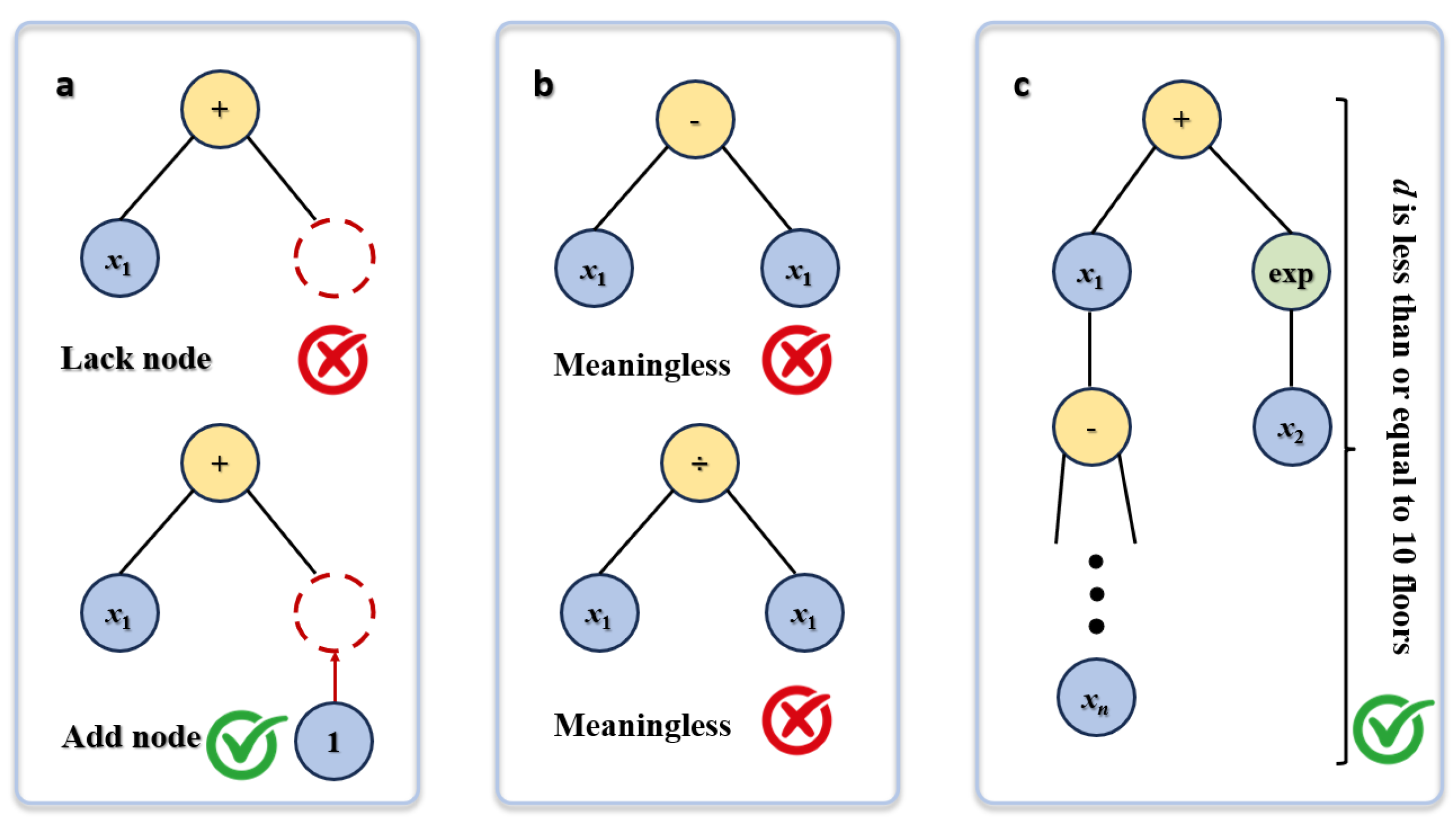
To address mathematically meaningless expressions in SR processes, MA-RSR designs an intelligent constraint mechanism, as illustrated in Figure 4. This mechanism dynamically constrains the action selection space of agents to fundamentally prevent syntax errors, semantic redundancy, and excessive complexity. The mechanism ensures that generated mathematical expressions conform to mathematical standards while possessing practical physical significance.
The syntax constraint shown in Figure 4a ensures that generated expressions conform to basic mathematical grammar rules. The system prohibits states when operator nodes lack necessary operands, allowing construction to continue only after complete operands are supplemented. The semantic constraint layer shown in Figure 4b aims to avoid generating mathematically equivalent or meaningless expressions. The system can identify and prohibit operations that produce identity transformations, such as redundant expressions, like x1 − x1 = 0 and x1/x1 = 1. The complexity constraint layer shown in Figure 4c controls overall complexity by limiting the maximum depth of expression trees.

4. Numerical Validations

This section presents the numerical evaluation of the MA-RSR framework for landing gear fatigue life prediction. Section 4.1 provides detailed descriptions of multiaxial fatigue test design and implementation processes using circular tubular specimens prepared from SAE4340 steel. Section 4.2 systematically compares performance differences in fatigue life prediction accuracy between MA-RSR methods and traditional empirical formulas, machine learning methods, and machine learning-based SR approaches based on experimental data.

4.1. Experimental Setup

To verify the applicability of MA-RSR methods in landing gear fatigue life prediction, this study selected SAE4340 steel widely used in aircraft landing gear manufacturing as the research object. SAE4340 steel possesses excellent strength, toughness, and fatigue performance. Considering the complex multiaxial loading characteristics that landing gear experiences during actual service, this study adopted circular tubular notched specimens as illustrated in Figure 5.
The specimens were prepared using precision machining, with geometric parameters optimized to effectively simulate stress concentration effects in landing gear structures. The specimens have an outer diameter of 18.7 mm, inner diameter of 12.7 mm, notch root diameter of 7.4 mm, and total length of 152.4 mm. This geometric configuration ensures that stress distribution under multiaxial loading resembles actual landing gear components while guaranteeing controllability and measurement accuracy of stress concentration regions during testing. The notch design adopts smooth transitions to avoid stress singularity problems that sharp corners might cause. Accurate acquisition of material fatigue characteristic parameters is a prerequisite for establishing reliable prediction models. Through standard material performance testing, complete mechanical property spectra of SAE4340 steel were systematically determined, with relevant parameters shown in Table 1.
The parameters in Table 1 cover complete fatigue characteristic descriptions of materials under uniaxial and shear loading conditions. The elastic modulus E and shear modulus G reflect the basic stiffness characteristics of the material. Fatigue strength coefficients σ′f and τ′f characterize the fatigue strength level of the material. Shear fatigue ductility coefficient γ′f and fatigue ductility coefficient ε′f and describe the plastic deformation capability of the material. Accurate determination of these parameters provides reliable material foundation data support for subsequent MA-RSR model training and validation.
Specimens generate alternating normal stress through rotating bending while bearing constant shear stress from constant torque, forming multiaxial fatigue loading. During testing, specimens rotate at a constant speed of 1750–1800 rpm under room temperature while simultaneously applying constant bending moment and constant torque loads. This loading mode effectively simulates the combined bending–torsion loading conditions that aircraft landing gear and rotating shaft components experience during actual service. To ensure reliability and comparability of test data, all specimens adopt uniform geometric dimensions and identical test conditions. Through systematic fatigue testing, complete fatigue data of SAE4340 steel under multiaxial symmetric loading conditions were obtained, with the test results shown in Table 2.
Comprehensive multiaxial fatigue experiments were conducted to obtain fatigue life data of SAE4340 steel under different stress ratio combinations. The experimental data spans four distinct loading conditions: pure axial loading, combined axial–torsional loading with moderate shear ratios, high shear-dominated loading, and pure torsional loading. Statistical analysis revealed that combined loading conditions generally resulted in 20–40% reduction in fatigue life compared to equivalent uniaxial loading, with the coefficient of variation ranging from 0.15–0.31, indicating typical scatter levels for metallic fatigue data. These experimental results provide an abundant data foundation for the construction and performance evaluation of the MA-RSR prediction model. In Table 2, σa represents normal stress, τa represents mean shear stress, εa and γa represent axial and shear strain amplitudes, respectively. Additionally, Nf represents fatigue life, while σIn(Nf) and μIn(Nf) represent the standard deviation and mean value of logarithmic fatigue life. The experimental program covered various loading conditions ranging from pure bending to combined bending–torsion loading scenarios. Stress levels spanned from high-cycle fatigue to low-cycle fatigue regions, ensuring comprehensive data coverage and representativeness.

4.2. MA-RSR Modeling and Performance Comparison

4.2.1. Formula Results Obtained from MA-RSR

Maintaining dimensional balance between expression sides represents a key factor for ensuring physical rationality in model construction. This study adopts dimensionless processing strategy, specifically replacing axial stress σ with σ/E and shear stress τ with τ/G. From material mechanics principles, Young’s modulus E reflects the material axial stiffness characteristics; thus, σ/E physically equals axial strain. Similarly, shear modulus G describes material resistance to shear deformation, while τ/G corresponds to shear strain. This processing method eliminates dimensional inconsistency problems while enhancing the physical interpretability of the model.
Based on the analysis above, the MA-RSR model input variables contain four core parameters: axial strain amplitude εa, shear strain amplitude γa, dimensionless axial stress σ/E, and dimensionless shear stress τ/G. These parameters comprehensively describe material mechanical response states under complex multiaxial loading conditions, with fatigue life Nf as the output variable. The dataset containing 252 experimental groups was input into MA-RSR algorithm for training, with each group containing four input parameters and one output target value. For training stability, all input variables are further standardized to the [0,1] range to facilitate convergence, while fatigue life values are used in logarithmic form (ln(Nf)) to handle the wide range of cycle counts typical in fatigue data. After multiple iterative optimizations, the MA-RSR algorithm successfully discovered two mathematical expressions with excellent fitting performance. Statistical analysis results demonstrate that both expressions achieve determination coefficients R2 of 0.96, with the generated expressions shown in Table 3.
Structural analysis of mathematical expressions generated by MA-RSR demonstrates that the model captures complex characteristics of material fatigue behavior through various mathematical forms. The exponential function f1(x) incorporates quadratic stress terms (σ/E)2 and interaction terms τ/G, physically representing the nonlinear damage accumulation under multiaxial loading. The logarithmic function f2(x) captures the power–law relationship inherent in fatigue crack propagation, while the square root function f3(x) reflects the influence of elastic–plastic deformation transitions on fatigue life. Taking exponential function f1(x) in Expression 1 as an example, it contains high-order terms (σ/E)2 and interaction terms τ/G, reflecting coupling effects between axial stress and shear stress. Threshold terms, such as −0.456 and 0.119 in f4(x) of Expression 2, indicate critical response characteristics in material fatigue damage processes. The mathematical structure of Formula 2 demonstrates the multi-component nature of fatigue behavior. The exponential component captures the rapid damage accumulation under high-stress conditions, while the logarithmic component represents the gradual damage evolution in strain-controlled regimes. The combination of these different mathematical forms enables the model to capture both high-cycle and low-cycle fatigue mechanisms within a unified framework.

4.2.2. Comparative Experiments

To comprehensively evaluate MA-RSR method effectiveness, this study selected multiple comparison methods for performance assessment. These methods include classical fatigue life prediction formulas (Coffin–Manson, KBM, FS, WHS criteria), machine learning methods (SVM, ANN), and SR methods, including genetic algorithm-based symbolic regression (GA-SR) and support vector machine-based symbolic regression (SVM-SR). The key hyperparameter settings for each method are presented in Table 4.
During model training processes, all hyperparameters of machine learning methods were systematically optimized through grid search, while material constants in classical fatigue formulas were set according to literature-recommended values. During model training and validation processes, the complete dataset containing 252 experimental groups was randomly divided into training and testing sets at an 8:2 ratio. After training and optimization, the fatigue life prediction results of various methods were visualized through scatter plots. Horizontal coordinates represent experimental true fatigue life values, while vertical coordinates represent prediction results from each method. Under ideal conditions, all data points should be distributed near the diagonal line. The experimental results are presented in Figure 6 below.
Comparative analysis of prediction results in Figure 6 reveals that all MA-RSR prediction points concentrate within the 2-fold error band, demonstrating excellent prediction stability across the entire fatigue life range from low-cycle (103 cycles) to high-cycle fatigue regimes (>106 cycles). Traditional empirical formulas, such as the FS criterion, exhibit significant systematic deviations with numerous prediction points exceeding the 3-fold error band, particularly overestimating fatigue life by factors of 3–5 in the high-cycle region due to limitations in capturing complex multiaxial stress interactions under non-proportional loading. Quantitative RMSE evaluation demonstrates that the MA-RSR method achieves optimal performance with substantial improvements across all benchmark methods. Specifically, MA-RSR achieves RMSE reductions of 61.3% compared to Coffin–Manson, 77.4% compared to KBM, and a remarkable 99.4% improvement over the FS criterion. Against the WHS method, MA-RSR shows a 74.4% RMSE reduction. When compared to machine learning approaches, MA-RSR demonstrates RMSE improvements of 64.1% over SVM and 52.7% over ANN. Even compared to other symbolic regression methods, MA-RSR outperforms GA-SR by 84.7% and SVM-SR by 26.7% in terms of RMSE reduction.
These substantial improvements indicate that the multi-agent collaborative mechanism and Transformer-based architecture effectively capture the complex multiaxial fatigue behavior. More importantly, unlike black-box machine learning methods, the generated mathematical expressions possess clear physical meaning and interpretability, providing effective tools for design and maintenance of critical safety components, like landing gear.

5. EngineeringValidation for Landing Gear Fatigue Life Prediction

5.1. Landing Gear Finite Element Modeling and Simulation Setup

Landing gear is a critical system that handles landing loads in aircraft, and its structural integrity directly affects flight safety. The landing gear structure mainly consists of support struts, shock absorbers, connecting brackets, and tire assemblies. For material selection, SAE4340 alloy steel is chosen as the landing gear material [31,32]. This material has the same mechanical properties as those used in previous fatigue experiments, ensuring data consistency between experiments and simulations.
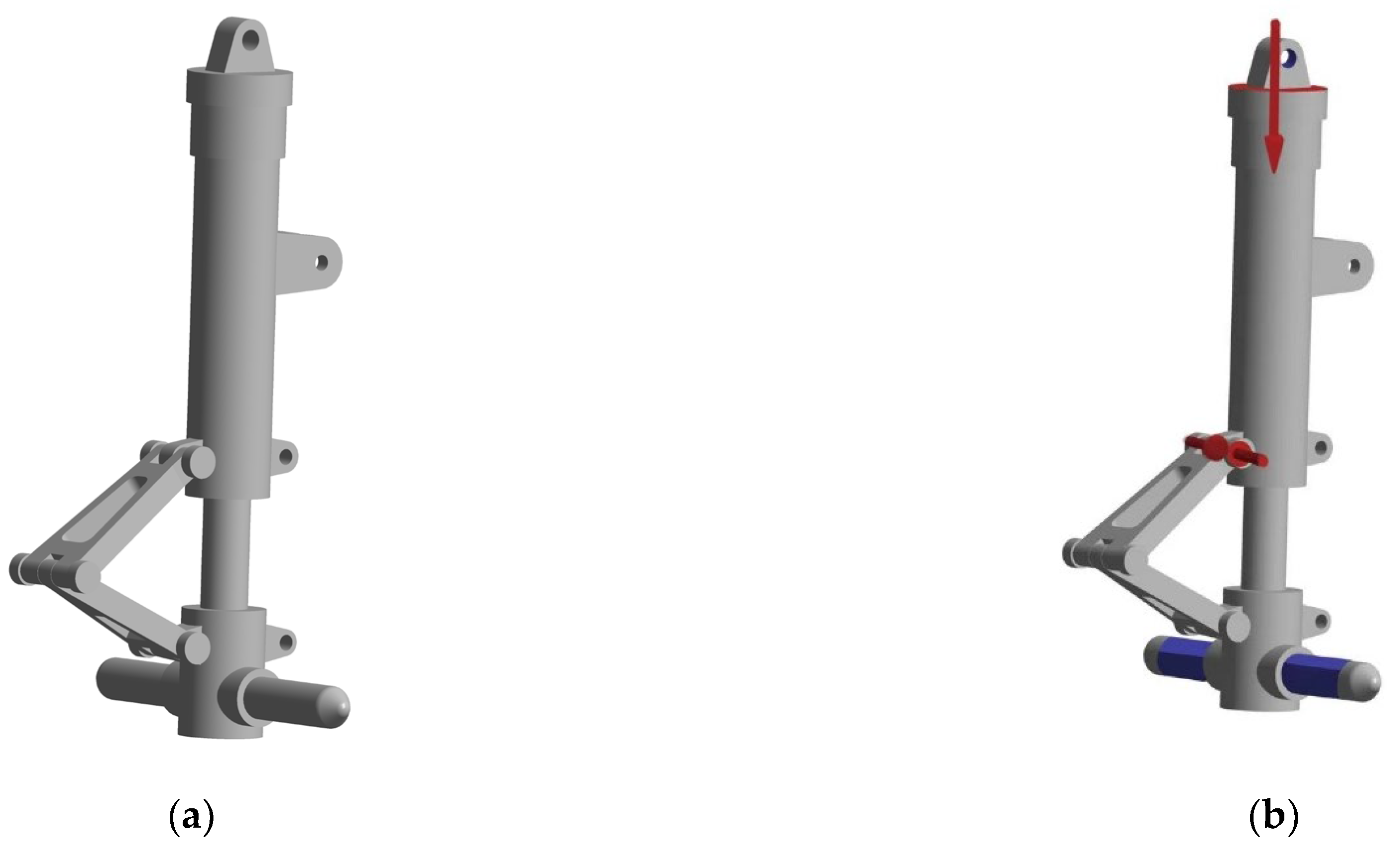
To accurately simulate landing gear behavior, finite element simulation setup employs the following simple strategies and assumptions under real service conditions: (1) complex dynamic landing processes are simplified to static loading conditions; (2) secondary factors, including aerodynamic loads and temperature effects, are ignored; (3) material is assumed to be isotropic linear elastic, without considering material nonlinearity. Regarding boundary conditions, fully fixed constraints are applied at the upper connection between the landing gear and fuselage to simulate a rigid connection with the main airframe structure. For load application, a vertically downward concentrated force of 277,950 N is used, determined based on the maximum takeoff weight and load distribution ratio, meeting airworthiness standards for design loads. A three-dimensional model and the specific boundary condition settings of the landing gear are shown in Figure 7.

5.2. Mesh Convergence Analysis and Verification

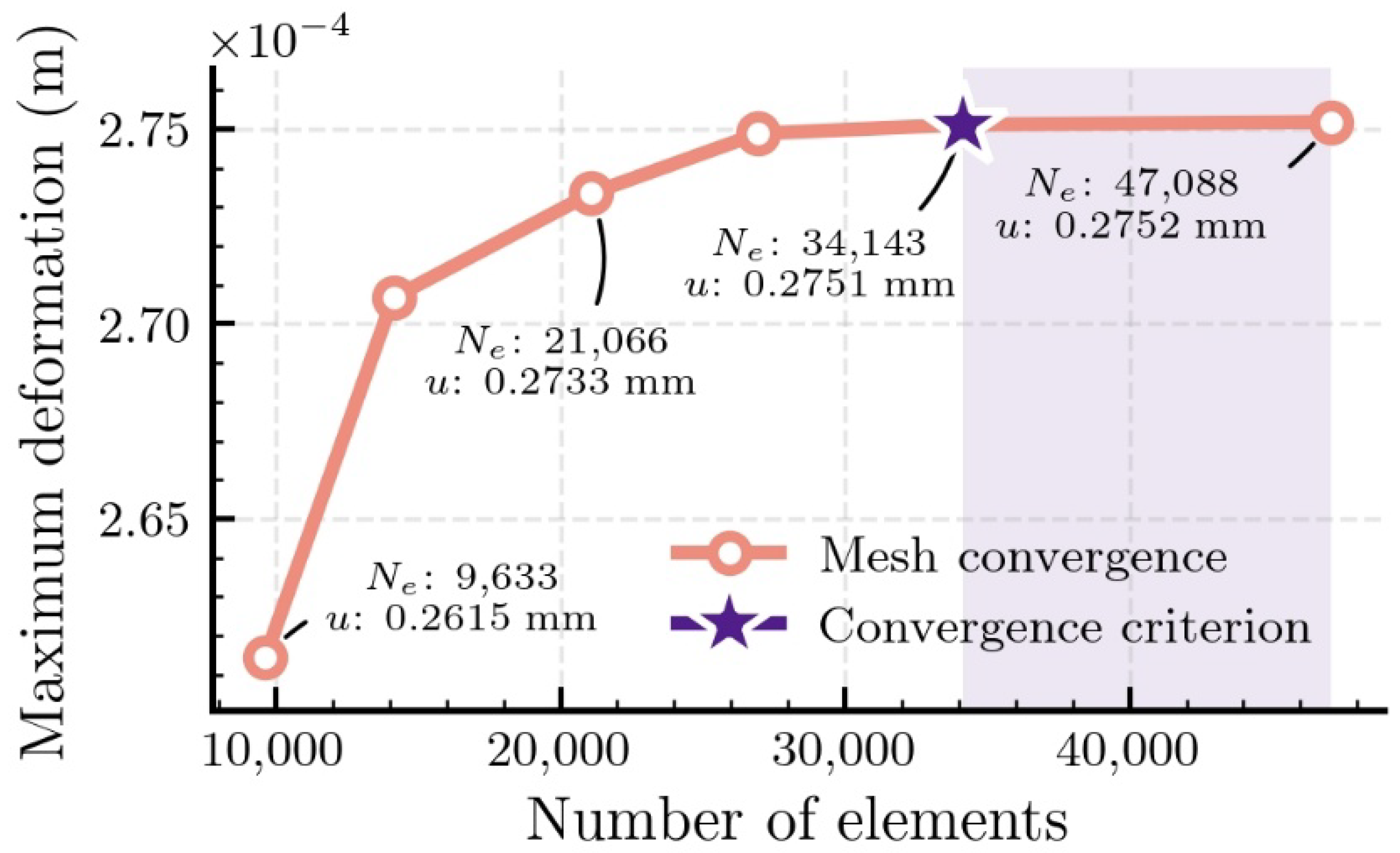
To ensure a balance between finite element simulation accuracy and computational efficiency, mesh convergence analysis was conducted on the landing gear model. Six different element sizes were employed for mesh independence verification, as shown in Table 5 and Figure 8. Maximum strain was selected as the primary indicator for convergence criteria because strain response is sensitive to mesh density and can effectively reflect the influence of mesh quality on computational results.
The calculation results in Table 5 show that maximum strain values tend to stabilize as mesh density gradually increases. When element size decreases from 15 mm to 7 mm, mesh element numbers increase from 9633 to 47,088, and maximum strain values gradually converge from 0.2615 mm/mm to 0.2752 mm/mm. Under 8 mm element size conditions, landing gear maximum strain reaches 0.2751 mm/mm. Compared with the finest mesh strain value of 0.2752 mm/mm, the relative error is only 0.036%, far below engineering accuracy requirements. The convergence curves in Figure 8 further verify this conclusion, showing that strain value trends become flat when mesh density reaches sufficient levels. Considering both computational accuracy and efficiency, an 8 mm element size was selected as the mesh configuration for subsequent analysis, ensuring accuracy while maintaining reasonable computational cost.

5.3. Fatigue Life Prediction Results and Comparative Analysis

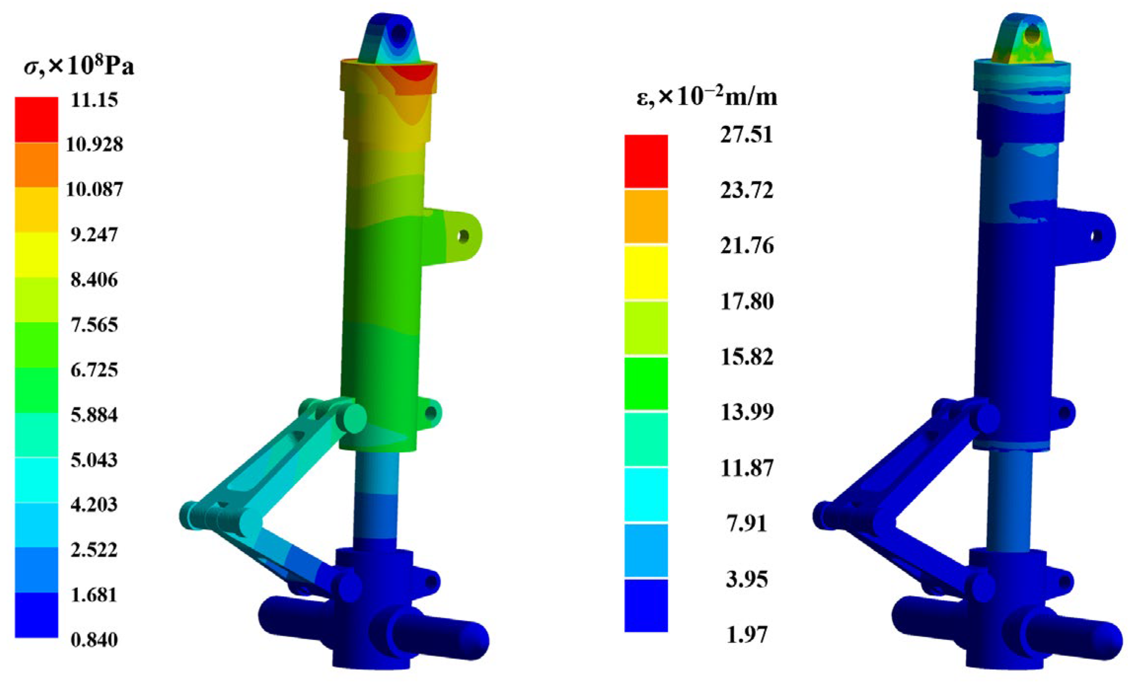
Detailed static analysis was conducted on the landing gear structure based on optimal mesh configuration determined from convergence analysis. Stress–strain distribution characteristics at critical locations were obtained through finite element simulation. Finite element simulation results revealed maximum equivalent stress of 1115 MPa under design loads on landing gear structure. Maximum stress concentration was primarily located in root region where support strut connects to fuselage. This region simultaneously exhibited the most severe stress gradient variations throughout the landing gear structure. The maximum equivalent strain reached 0.2751 mm/mm according to finite element simulation analysis results. Stress and strain simulation contours of the landing gear structure are illustrated in Figure 9.
To comprehensively evaluate the effectiveness of the proposed MA-RSR method in landing gear fatigue life prediction, this study systematically compared its prediction results with eight classical and advanced fatigue life prediction methods. These comparative methods encompass traditional empirical formulas (Coffin–Manson, KBM, FS, WHS criteria), machine learning algorithms (SVM, ANN), and SR methods (GA-SR, SVM-SR). Based on stress–strain data obtained from finite element simulations, the fatigue life prediction results of various methods show significant differences. Table 6 presents a comprehensive comparison of predicted fatigue life values among MA-RSR, traditional empirical formulas, and machine learning methods:
The obtained results show similar trend characteristics, demonstrating the preliminary feasibility of combining the RSR method with landing gear simulation for fatigue life prediction. As the fatigue test dataset expands and simulation accuracy improves, the prediction accuracy of lifecycle values will be further verified. This provides reliable reference for maintenance and repair of critical components in future engineering applications, offering scientific guidance for lifecycle management of critical components.

6. Conclusions

This paper proposes a MA-RSR method to address limitations of traditional fatigue life prediction approaches and lack of interpretability in machine learning methods for aircraft landing gear applications. The method combines multi-agent reinforcement learning with SR to achieve high-precision and interpretable fatigue life prediction. The main conclusions are as follows:
(1)
Based on 252 sets of SAE4340 steel multiaxial fatigue data, MA-RSR achieves an R2 of 0.96, significantly outperforming traditional empirical formulas (Coffin–Manson, KBM, FS, WHS) and machine learning methods (SVM, ANN), with prediction accuracy improvements exceeding 50% in most cases.
(2)
The multi-agent collaborative mechanism effectively addresses search space explosion by decomposing complex expressions into parallel components. Transformer architecture enhances symbolic selection through self-attention mechanisms, while intelligent masking ensures mathematical rationality through multi-level constraints including syntax, semantics, and complexity control.
(3)
Generated expressions maintain clear physical interpretability while achieving superior accuracy. Landing gear finite element validation confirms practical applicability under realistic conditions, providing an effective tool for complex engineering structure fatigue analysis.
(4)
MA-RSR successfully balances modeling accuracy with interpretability, making it promising for complex engineering reliability analysis. The method provides scientific guidance for critical aircraft component fatigue assessment and advances SR applications in engineering domains.
The proposed MA-RSR framework offers significant potential for practical integration into aerospace industry design and maintenance workflows. In the design phase, the method can be incorporated into existing computer-aided engineering (CAE) systems as an intelligent fatigue assessment module, enabling rapid evaluation of component designs without extensive physical testing. For maintenance applications, the framework can support condition-based maintenance strategies by providing real-time fatigue life estimates based on operational load monitoring data, allowing maintenance schedules to be optimized based on actual usage rather than conservative time-based intervals. The interpretable mathematical expressions generated by MA-RSR facilitate regulatory approval processes and enable engineers to understand the physical mechanisms driving fatigue behavior, making it particularly suitable for safety-critical aerospace applications where model transparency is essential.
However, several limitations in MA-RSR warrant further investigation. Firstly, the current research primarily focuses on SAE4340 steel material, and the adaptability and generalization capability for other aerospace materials require further verification. Secondly, the framework performance with small or noisy datasets remains unexplored, which is critical given the typically limited availability and high cost of fatigue testing data in real-world applications. Furthermore, the current reward function relies solely on RMSE, which may not adequately balance accuracy with model simplicity and generalization capability. Additionally, the existing model does not adequately consider the effects of environmental factors, such as temperature and corrosion on fatigue life, which limits its application in complex service environments. The current study acknowledges several dataset constraints: the 252 experimental data points represent a relatively small sample size for complex machine learning applications, the exclusive focus on SAE4340 steel limits direct applicability to other aerospace materials, and the multiaxial loading coverage may not fully represent the diverse loading spectra encountered in actual service conditions. Finally, the landing gear finite element simulation employs a simplified static load model that cannot fully reflect the complex load spectra during real dynamic landing processes. Future research could address these limitations through specific extensions, including environmental effects integration with temperature-dependent material properties and corrosion-fatigue interactions, time-dependent loading considerations through variable amplitude loading and load sequence effects, hybrid FEM-MA-RSR models for online fatigue life assessment, multi-material modeling with expanded datasets covering various aerospace alloys, and advanced uncertainty quantification approaches to provide confidence intervals alongside point predictions, ultimately improving the accuracy and efficiency of MA-RSR in complex engineering scenarios.

Author Contributions

Conceptualization, C.-W.F. and J.-R.W.; methodology, H.F. and Y.-P.S.; software, Y.-P.S.; validation, A.-F.C. and B.Z.; formal analysis, Y.-P.S.; investigation, Y.-P.S. and H.F.; resources, B.Z.; data curation, H.F. and A.-F.C.; writing—original draft preparation, Y.-P.S.; writing—review and editing, Y.-P.S. and J.-R.W.; visualization, J.-R.W.; supervision, C.-W.F.; project administration, C.-W.F.; funding acquisition, C.-W.F. All authors have read and agreed to the published version of the manuscript.

Funding

This paper is co-supported by the National Natural Science Foundation of China (Grant No. 52375237) and National Science and Technology Major Project (Grant No. J2022-IV-0012). The authors would like to thank them.

Data Availability Statement

The data used to support the findings of this study are included within the article.

Conflicts of Interest

The authors declare no conflicts of interest related to this publication.

References

  1. Tang, H.; Liu, P.; Ding, J.; Cheng, J.; Jiang, Y.; Jiang, B. Numerical prediction of fatigue life for landing gear considering the shock absorber travel. Aerospace 2025, 12, 42. [Google Scholar] [CrossRef]
  2. Deng, K.; Ompusunggu, A.; Xu, Y.; Stoke, M.; Zhao, Y. A review of material-related mechanical failures and load monitoring-based structural health monitoring (SHM) technologies in aircraft landing gear. Aerospace 2025, 12, 266. [Google Scholar] [CrossRef]
  3. Ni, P. Strength analysis of shock strut of aircraft landing gear based on ANSYS. In Proceedings of the IEEE 10th Conference on Systems, Process & Control (ICSPC), Advanced Materials Reaserch, Malacca, Malaysia, 17 December 2022; pp. 111–116. [Google Scholar]
  4. Aditya, A.; Sharma, K.; Srinivas, G. A step towards safety: Material failure analysis of landing gear. Mater. Today 2020, 27, 402–409. [Google Scholar]
  5. Basquin, O. The exponential law of endurance tests. Am. Soc. Test. Mater. 1910, 10, 625–630. [Google Scholar]
  6. Coffin, L. A study of the effects of cyclic thermal stresses on a ductile metal. Trans. ASME 1954, 76, 931–949. [Google Scholar] [CrossRef]
  7. Manson, S. Behavior of Materials Under Conditions of Thermal Stress; National Advisory Committee for Aeronautics: Washington, DC, USA, 1953; pp. 29–33. [Google Scholar]
  8. Morrow, J. Cyclic Plastic Strain Energy and Fatigue of Metals; ASTM International: West Conshohocken, PA, USA, 1965; pp. 45–87. [Google Scholar]
  9. Ni, X.; Yin, Q.; Wei, X.; Zhong, P.; Nie, H. Research on landing stability of four-legged adaptive landing gear for multirotor UAVs. Aerospace 2022, 9, 776. [Google Scholar] [CrossRef]
  10. Findley, W. A theory for the effect of mean stress on fatigue of metals under combined torsion and axial load or bending. J. Eng. Ind. 1959, 81, 301–305. [Google Scholar] [CrossRef]
  11. Brown, M.; Miller, K. A theory for fatigue failure under multiaxial stress-strain conditions. Proc. Inst. Mech. Eng. 1973, 187, 745–755. [Google Scholar] [CrossRef]
  12. Fatemi, A.; Socie, D. A critical plane approach to multiaxial fatigue damage including out-of-phase loading. Fatigue Fract. Eng. Mater. Struct. 1988, 11, 149–165. [Google Scholar] [CrossRef]
  13. Wu, Z.; Hu, X.; Song, Y. Multiaxial fatigue life prediction for titanium alloy TC4 under proportional and nonproportional loading. Int. J. Fatigue 2014, 59, 170–175. [Google Scholar] [CrossRef]
  14. Le, C.; Ferrer, E.; Gibson, S.; Cross, E.; Parente, A.; Vinuesa, R. Improving aircraft performance using machine learning: A review. Aerosp. Sci. Technol. 2023, 138, 108354. [Google Scholar] [CrossRef]
  15. Sun, Y.; Wen, J.; Li, J.; Cao, A.; Fei, C. Novel integrated model approach for high cycle fatigue life and reliability assessment of helicopter flange structures. Aerospace 2025, 12, 78. [Google Scholar] [CrossRef]
  16. Zhang, X.; Liu, F.; Shen, M.; Han, D.; Wang, Z.; Yan, N. Ultra-high-cycle fatigue life prediction of metallic materials based on machine learning. Appl. Sci. 2024, 13, 2524. [Google Scholar] [CrossRef]
  17. Heng, F.; Gao, J.; Xu, R.; Yang, H.; Cheng, Q.; Liu, Y. Multiaxial fatigue life prediction for various metallic materials based on the hybrid CNN-LSTM neural network. Fatigue Fract. Eng. Mater. Struct. 2023, 46, 1979–1996. [Google Scholar] [CrossRef]
  18. Farhadi, S.; Tatullo, S.; Ferrian, F. Comparative analysis of ensemble learning techniques for enhanced fatigue life prediction. Sci. Rep. 2025, 15, 11136. [Google Scholar] [CrossRef]
  19. Liao, W.; Long, X.; Jiang, C. A physics-informed neural network method for identifying parameters and predicting remaining life of fatigue crack growth. Int. J. Fatigue 2025, 191, 108678. [Google Scholar] [CrossRef]
  20. Tenachi, W.; Ibata, R.; Diakogiannis, F. Deep symbolic regression for physics guided by units constraints: Toward the automated discovery of physical laws. Astrophys. J. 2023, 959, 99. [Google Scholar] [CrossRef]
  21. Zhang, P.; Tang, K.; Wang, A.; Wu, H.; Zhong, Z. Neural network integrated with symbolic regression for multiaxial fatigue life prediction. Int. J. Fatigue 2024, 188, 108535. [Google Scholar] [CrossRef]
  22. Cao, W.; Sun, X.; Chen, X. Estimation and validation for fatigue properties of steels by symbolic regression. Int. J. Fatigue 2024, 186, 108416. [Google Scholar] [CrossRef]
  23. Feng, S.; Sun, X.; Chen, C.; Wu, H.; Chen, X. LBE corrosion fatigue life prediction of T91 steel and 316 SS using machine learning method assisted by symbol regression. Int. J. Fatigue 2023, 177, 107962. [Google Scholar] [CrossRef]
  24. Ding, D.; Wang, Q.; Chen, Q.; He, L. Symbolic Regression-Based Modeling for Aerodynamic Ground-to-Flight Deviation Laws of Aerospace Vehicles. Aerospace 2025, 12, 455. [Google Scholar] [CrossRef]
  25. Li, P.; Choi, J.; Zhang, D.; Zhang, S.; Zhang, Y. Reinforced symbolic learning with logical constraints for predicting turbine blade fatigue life. Aerosp. Sci. Technol. 2025, 158, 109888. [Google Scholar] [CrossRef]
  26. Fei, C.; Han, Y.; Wen, J.; Li, C.; Han, L.; Choy, Y.S. Deep learning-based modeling method for probabilistic LCF life prediction of turbine blisk. Propuls. Power Res. 2024, 13, 12–25. [Google Scholar] [CrossRef]
  27. Udrescu, S.; Tegmark, M. AI Feynman: A physics-inspired method for symbolic regression. Sci. Adv. 2020, 6, eaay2631. [Google Scholar] [CrossRef] [PubMed]
  28. Matchev, K.; Matcheva, K.; Roman, A. Analytical modeling of exoplanet transit spectroscopy with dimensional analysis and symbolic regression. Astrophys. J. 2022, 930, 33. [Google Scholar] [CrossRef]
  29. Lin, J.; Li, C.; Chao, A.; Fei, C.; Ren, Q. Design and performance evaluation of novel wing-shaped fin radiators for advanced aeroengines. Propuls. Power Res. 2025, 14. [Google Scholar]
  30. Wen, J.; Zheng, B.; Fei, C. Prioritized Experience Replay-based Adaptive Hybrid Method for Aerospace Structural Reliability Analysis. Aerosp. Sci. Technol. 2025, 163, 110257. [Google Scholar] [CrossRef]
  31. Milan, M.; Spinelli, D.; Bose, F.; Montezuma, M.; Tita, V. Failure analysis of a SAE 4340 steel locking bolt. Eng. Fail. Anal. 2004, 11, 915–924. [Google Scholar] [CrossRef]
  32. Fratesi, R.; Roventi, G.; Cavallini, M. Hydrogen-inclusion interaction in tempered martensite embrittled SAE 4340 steels. Mater. Sci. Eng. A 1989, 119, 17–22. [Google Scholar] [CrossRef]
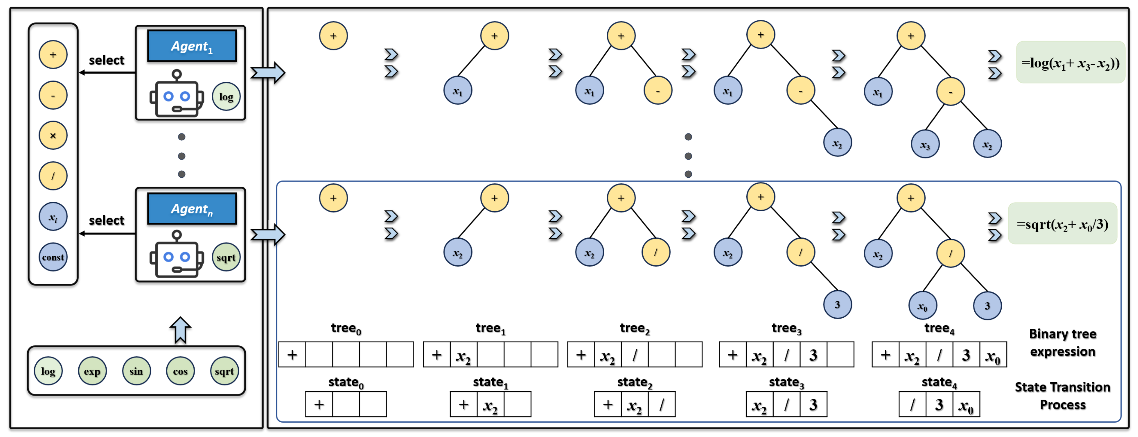
Figure 1. Multi-agent collaborative architecture and state transition process.
Aerospace 12 00718 g001
Figure 2. Transformer-guided individual agent expression node selection process.
Aerospace 12 00718 g002
Figure 3. Actor–Critic reinforcement learning architecture.
Aerospace 12 00718 g003
Figure 4. Intelligent constraint mechanism with syntax, semantic, and complexity constraints.
Aerospace 12 00718 g004
Figure 5. Geometric dimensions of SAE4340 steel circular tubular notched specimen.
Aerospace 12 00718 g005
Figure 6. Comparison of fatigue life prediction results for SAE4340 steel using different methods.
Aerospace 12 00718 g006
Figure 7. Three-dimensional model and boundary condition settings of landing gear. (a) Three-dimensional model; (b) applied loads and boundary constraints.
Aerospace 12 00718 g007
Figure 8. Mesh convergence analysis.
Aerospace 12 00718 g008
Figure 9. Stress and strain simulation contours of the landing gear.
Aerospace 12 00718 g009
Table 1. Fatigue performance parameters of SAE4340 steel material.
E/GPaG/GPaσ′f/MPaτ′f/MPaγ′fε′f
2078016589570.8450.563
bcb0c0νeνp
−0.074−0.513−0.074−0.5130.290.29
Table 2. Multiaxial fatigue experimental results of SAE4340 steel.
Materialσa
(MPa)
τa
(MPa)
εa
(%)
γa
(%)
Nf
(cycles)
σIn(Nf)μIn(Nf)n
SAE434099300.523027730.2287.90612
SAE434078600.414090290.1169.10218
SAE434067600.356022,1710.1769.99218
SAE434055800.294077,9770.15411.25318
SAE434050300.2650161,9840.23211.97118
SAE434010411720.5480.23614510.1987.26312
SAE43407931340.4170.18562030.1578.72118
SAE4340572930.3010.12839,6080.20710.54518
SAE4340510860.2690.11974,2120.27411.1818
SAE43407655070.4030.69865540.1468.77812
SAE43406344580.3340.63120,4670.2819.8918
SAE43405243690.2760.50861,0280.18111.06218
SAE43404483240.2360.447127,5770.16711.74318
SAE43404766210.2510.85653,5730.24410.85718
SAE43404145410.2180.746142,5500.30511.82518
Table 3. Expression structures of MA-RSR for fatigue life prediction.
FormulaFunction TypeMathematical ExpressionR2
1Exp(f1(x)) ( σ a E ) 2 τ a G ( γ a 9.395 ε a 2 + 2.587 ) 3.757 1.360 γ a + τ a G 2 ε a 2 0.9689
Log(f2(x)) 0.0241 σ a E 7.473 γ a + ( 0.587 τ a G ) τ a G γ a + 4.294 2 σ a E + 2.102
Sqrt(f3(x)) 3.303 × 10 5 ( 2 σ a E + ε a 5.741 ) ( ε a + 0.128 γ a ) + 9.309 × 10 5
f4(x) σ a E [ ( τ a G 0.919 ) ( γ 0.048 ) ( 0.264 γ ) + 0.116 σ a E ] 0.045 ( τ a G σ a E ) + 0.235 0.376 ε
2Exp(f1(x)) ( σ a E ) 2 σ a E γ a 5.027 ( σ a E 0.791 ) + γ a + 2.186 τ a G ( σ a E + 0.544 ) 4.135 0.9672
Log(f2(x)) 1.770 ε a + 0.563 γ a 2 + 0.481 + τ a G + 0.313 σ a E ( γ a + ( σ a E ) 2 ) 1.177 2.644
Sqrt(f3(x)) 3.754 × 10 5 0.132 ε a 0.117 + 0.226 + τ a G ε a 1.431 + 0.731 + 1.226 2.879 × 10 5
f4(x) 1.690 ε a 0.866 × 0.0795 ε a 1 τ a G ( γ a 0.456 ) 2.686 ( τ a G 0.117 ) 0.0282 γ a + 0.119
Table 4. Hyperparameter settings of comparative methods.
Parameter TypeSVMANNGA-SRKBMFSWHS
Core ParametersC = 100
γ = 0.1
Hidden layer = 64
Learning rate = 0.001
Population = 100
Generations = 500
S = 0.2k = 0.3k = 0.4
Algorithm SettingsRBF kernel functionAdam optimizerCrossover rate = 0.8---
Table 5. Validation of finite element model with different element sizes.
Element Size (mm)Number of ElementsStress, MPaStrain, m/m
159633874.750.2615
1215,127887.700.2707
1021,866936.820.2733
926,9551116.440.2750
834,1431115.270.2751
747,0881116.870.2752
Table 6. Comparison of fatigue life prediction between MA-RSR, empirical formulas, and machine learning models.
Nf of
CM
Nf of KBMNf of FSNf of WHSNf of SVMNf of ANNNf of GA-SRNf of
SVM-SR
Nf of
MA-RSR
Life
(cycles)
124728918654342941564738589252346127
Disclaimer/Publisher’s Note: The statements, opinions and data contained in all publications are solely those of the individual author(s) and contributor(s) and not of MDPI and/or the editor(s). MDPI and/or the editor(s) disclaim responsibility for any injury to people or property resulting from any ideas, methods, instructions or products referred to in the content.