Article

Structural-Integrated Electrothermal Anti-Icing Components for UAVs: Interfacial Mechanisms and Performance Enhancement

1
College of Mechanical and Electrical Engineering, Nanjing University of Aeronautics and Astronautics, Nanjing 210016, China
2
Tianjin Aviation Electro-Mechanical Co., Ltd., Tianjin 300308, China
3
Songshan Lake Materials Laboratory, Dongguan 523808, China
*
Authors to whom correspondence should be addressed.
Aerospace 2025, 12(8), 719; https://doi.org/10.3390/aerospace12080719
Submission received: 26 May 2025 / Revised: 30 July 2025 / Accepted: 5 August 2025 / Published: 13 August 2025
(This article belongs to the Special Issue Deicing and Anti-Icing of Aircraft (Volume IV))

Abstract

Icing represents a significant hazard to the flight safety of unmanned aerial vehicles (UAVs), particularly affecting critical aerodynamic surfaces such as air intakes, wings, and empennages. While conventional adhesive electrothermal de-icing systems are straightforward to operate, they present safety concerns, including a 15–25% increase in system weight, elevated anti-/de-icing power consumption, and the risk of interlayer interface delamination. To address the objectives of reducing weight and power consumption, this study introduces an innovative electrothermal–structural–durability co-design strategy. This approach successfully led to the development of a glass fiber-reinforced polymer (GFRP) component that integrates anti-icing functionality with structural load-bearing capacity, achieved through an embedded hot-pressing process. A stress-damage cohesive zone model was utilized to accurately quantify the threshold of mechanical performance degradation under electrothermal cycling conditions, elucidating the evolution of interfacial stress and the mechanism underlying interlayer failure. Experimental data indicate that this novel component significantly enhances heating performance compared to traditional designs. Specifically, the heating rate increased by approximately 202%, electrothermal efficiency improved by about 13.8% at −30 °C, and interlayer shear strength was enhanced by approximately 30.5%. This research offers essential technical support for the structural optimization, strength assessment, and service life prediction of UAV anti-icing and de-icing systems in the aerospace field.

1. Introduction

When aircraft encounter clouds containing supercooled water droplets, ice rapidly accumulates on the surfaces of aircraft wings, empennages, and engine intakes. This accumulation results in a significant deterioration of aircraft handling characteristics, potentially leading to catastrophic safety incidents, including aircraft destruction and fatalities [1,2]. Electrothermal anti-icing systems have been extensively implemented in critical ice protection areas such as intakes, wings, and empennages due to their high efficiency and precise control. However, traditional discrete anti-/de-icing design schemes present two major drawbacks: a 15–25% increase in system weight and vulnerability to interfacial debonding and delamination under thermal stress cycling [3,4,5]. This approach involves adhesively bonding metal heating elements to the load-bearing structural surfaces of the aircraft matrix. The mismatch in the coefficient of thermal expansion between metal and composite materials induces mechanical–thermal mismatches, which significantly diminish interlaminar strength. As unmanned aerial vehicles (UAVs) progress towards electrification and lightweight construction, the constraints related to weight and anti-icing/de-icing power consumption become increasingly stringent. The limitations associated with traditional discrete solutions—namely, excessive weight redundancy and insufficient interfacial reliability—are further exacerbated, thereby rendering these solutions progressively inadequate. In this context, there is a pressing need to develop a lightweight, efficient, and reliable integrated anti-icing structural solution. This technical approach incorporates anti-icing functionality within the structural design, fundamentally addressing interface issues and weight redundancy inherent in separate designs, while maintaining anti-icing/de-icing efficiency and structural integrity.
Functional–structural integration presents significant potential for reducing aircraft weight and enhancing anti-icing performance. Pioneering research in lightweight electrothermal anti-icing and de-icing technology has been conducted by NASA in the United States and Airbus in Europe. A notable application is the incorporation of fiber metal laminate (FML)-embedded heating elements in the leading edge of the Airbus A380 wing [6], which exemplifies the electrothermal–load-bearing–durability collaborative design concept detailed in NASA’s 2020 Technology Roadmap [7]. Mohseni et al. [8] implemented a hybrid system composed of glass fiber-reinforced polymer (GFRP) and nichrome alloy, achieving a 9.8% reduction in the power consumption of wind turbine blades. Similarly, Niu et al. [9] developed a hybrid thin film consisting of carbon nanotubes and reduced graphene oxide, which resulted in a 43.5% decrease in de-icing energy consumption. In terms of manufacturing techniques, Grzegorz et al. [10] employed a combined spraying and screen-printing method, offering an initial solution for the production of large-area, cost-effective carbon nano heating elements. Furthermore, Ibrahim et al. [11] utilized 3D printing technology to fabricate continuous metal wire polymer composite structures, which enabled rapid manufacturing with a significant reduction in energy consumption of approximately 50%.
However, two significant challenges remain in engineering applications: traditional metal–composite interfaces produced through manual adhesive bonding processes exhibit internal porosity and inadequate interlaminar bonding strength [12,13,14]. Additionally, mismatched coefficients of thermal expansion and potential issues of interface delamination or detachment arise within the operational stress range of −55 to 80 °C for anti-icing/de-icing components. Müller et al. [15,16] found that within the temperature range of −25 to 95 °C, composite fiber metal laminates exhibited a 7.8% reduction in interlaminar shear strength (ILSS) after 12,000 cycles. Li et al. [17] utilized sprayable metal film (SMF) as heating elements and observed a 16.67% reduction in resistive heating power following thermal and mechanical cycling, with the heating elements failing prior to any structural damage. Wu et al. [18] conducted an investigation into the electrothermal functional fatigue characteristics of de-icing composite laminates. Following 1000 thermal cycles, the specimens demonstrated a 20.46% increase in electrical resistance and a 17.02% reduction in heating power. Nevertheless, the underlying mechanisms governing the internal electrothermal behavior remain insufficiently explored. In a related study, Cheng et al. [19] developed an innovative carbon fiber/epoxy resin laminate by depositing graphene nanoplatelets (GnP) and phenolic resin (PF) onto the surfaces of carbon fibers. This approach resulted in a 37.04% improvement in interlaminar shear strength and a 16.67% enhancement in thermal conductivity. Despite these advancements, further comprehensive research is necessary to elucidate the mechanisms of interlaminar reinforcement.
Current integrated functional–structural anti-icing and de-icing technologies face urgent challenges that necessitate the resolution of two fundamental scientific issues: the performance evolution under prolonged electrothermal cycling and the failure mechanisms associated with electrothermal effects on interlaminar mechanics. These critical aspects remain inadequately explored in systematic research. This study introduces a cohesive zone model that incorporates electrothermal stress effects, elucidating the degradation mechanisms at the functional layer interface within integrated functional–structural components. By employing an embedded co-curing process, we developed glass fiber reinforced composite (GFRP) integrated anti-icing and de-icing components, which demonstrate three significant advantages over conventional designs: a 202% relative increase in heating rate, a 13.8% relative improvement in heating efficiency at −30 °C, and a 30.5% enhancement in interlaminar shear strength (ILSS). This study employs a combination of 20,000-cycle thermal fatigue testing and scanning electron microscopy (SEM) analysis to investigate the evolutionary mechanism of interfacial failure induced by thermal stress. The results have substantial engineering implications for assessing the durability and strength of functionally–structurally integrated anti-icing and de-icing systems.

2. Materials and Methods

2.1. Anti-Icing/De-Icing Structure Design

Electrothermal anti-icing and de-icing components are designed using two primary structural configurations: the discrete structure and the functionally–structurally integrated type. The discrete structure involves the traditional method of attaching heating elements to substrate surfaces through secondary processing. This approach is noted for its straightforward manufacturability but is limited by lower interfacial bonding strength. In the following sections, this configuration will be referred to as Sample 1. In contrast, the functional–structural integration involves an integrated co-curing process that embeds heating elements within the layers of composite materials, resulting in enhanced interfacial properties and a reduction in weight. This configuration will be referred to as Sample 2 in subsequent discussions.
Traditional electrothermal anti-icing and de-icing systems typically exhibit a discrete configuration in which the heating elements are separate from the structural skin, necessitating post-installation attachment using adhesive, as shown in Figure 1a. In contrast, the functionally integrated prototype examined in this study employs an innovative electrothermal–load-bearing co-design approach. This involves an embedded hot-pressing technique that simultaneously couples and co-cures the heating element with the structural component, as depicted in Figure 1b. The functionally integrated electrothermal heating assembly comprises an aluminum alloy metal layer encapsulated within a glass fiber reinforced polymer (GFRP) matrix. This assembly functions as an anti-icing component for the leading edges of aircraft wings and empennages. During typical flight conditions, it is designed to withstand thermal cycling stress loads ranging from −55 to 80 °C.
The integrated functional–structural anti-icing/de-icing component introduced in this study offers substantial advantages in lightweight design over conventional discrete heating systems. Traditional electrothermal anti-icing/de-icing assemblies employ a discrete structure, wherein heating elements are secondarily bonded to the skin structure using adhesive. These systems necessitate the external attachment of heating films or wires (e.g., metal alloys), adhesive bonding layers, and protective layers, resulting in an added weight typically ranging from 1.2 to 1.5 kg/m2, depending on the substrate material thickness. The subsequent assembly processes often leads to interfacial stress concentration and increases the system weight by approximately 15% to 25%. This paper proposes a functional–structural integration anti-/de-icing design solution by embedding heating elements directly into the GFRP matrix, thereby reducing the need for intermediate adhesive layers. This approach decreases the density to between 0.8 and 1.0 kg/m2. Such a technical solution is particularly applicable to weight-sensitive fields, such as aviation and wind power. For example, reducing the weight of de-icing systems in aircraft wings and empennages can lead to decreased fuel consumption.

2.2. Experimental Materials

The electrothermal components utilized in this study were flexible HL-368-E heating films, characterized by a thickness of 0.3 mm and procured from Jiangsu Huilong Electric Heating Appliances Co., Ltd. (Jiangyin, Jiangsu Province, China). The external casing was constructed from an aluminum alloy (Grade 3A21), with dimensions of 56 mm × 28 mm × 2 mm, and was supplied by Guangdong Xingfa Aluminium Co., Ltd. (Foshan, Guangdong Province, China).The glass fiber employed was an orthogonally woven material (Model E-7202), sourced from Tianjin Hanshuo Advanced Materials Co., Ltd. (Tianjin, China), featuring a surface density of 200 g/m2 and a glass fiber volume fraction of 60%. The dimensions of the glass fiber were 56 mm × 28 mm. Detailed material parameters for the anti-/de-icing heating component are presented in Table 1.

2.3. Preparation Process

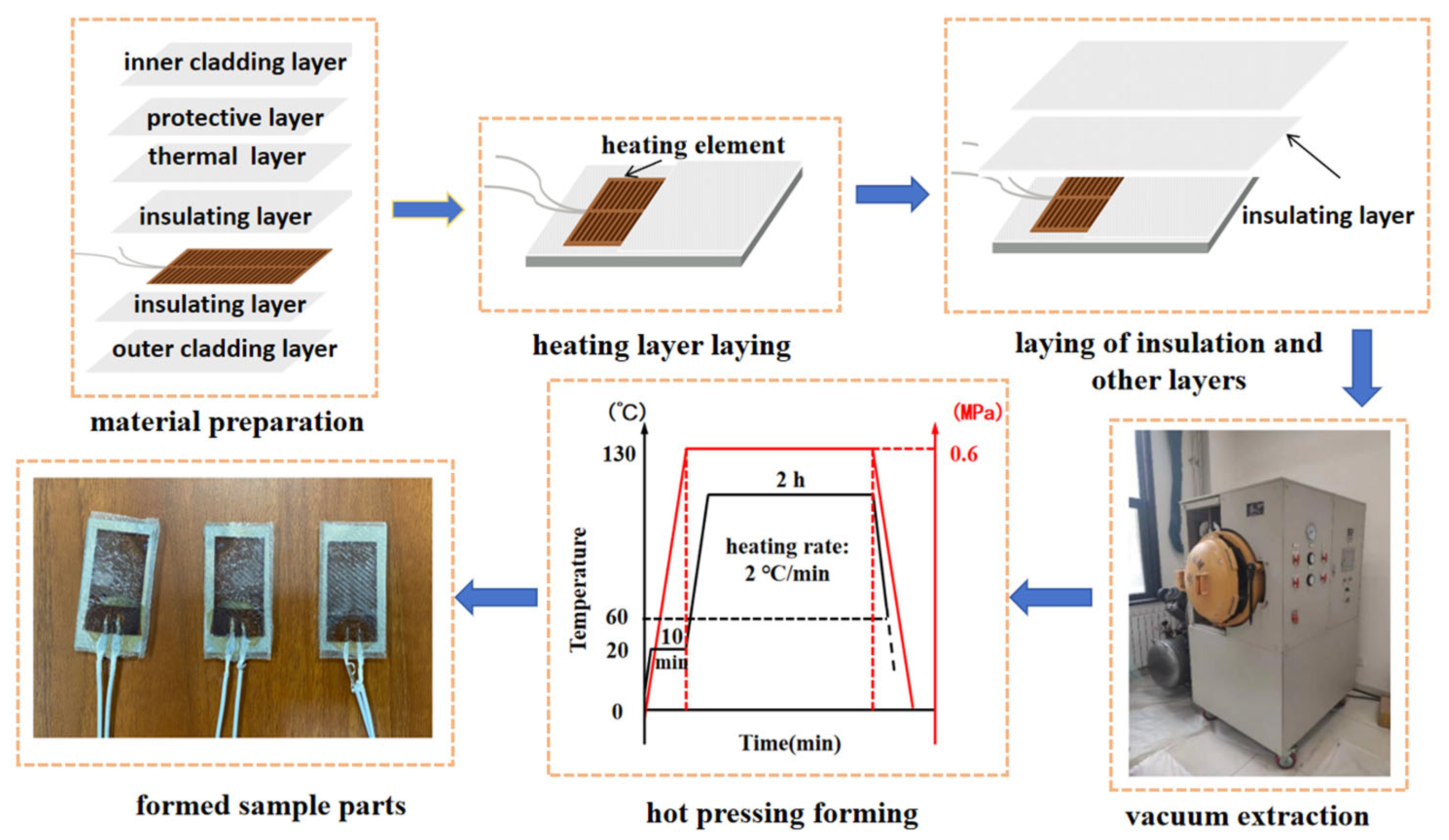
The co-curing process utilized in this study represents an integrated technique that concurrently hot-press forms both the functional layers (e.g., metal heating elements) and structural matrix (e.g., glass fiber reinforced composites) within a single curing cycle. This method offers the significant advantage of eliminating the adhesive layer typically required in conventional secondary bonding, thereby reducing weight by 20–35%. By exerting precise control over pressure and temperature during the hot-pressing process, the formation of internal defects such as voids during resin curing is effectively mitigated. The manufacturing process for the integrated functional–structural anti-icing/de-icing component using co-curing technology, as depicted in Figure 2, involves three distinct stages: the pretreatment stage, the lay-up process stage, and the curing formation stage. The specific fabrication sequence is as follows:
(1)
Pretreatment Stage
Initially, the prepreg should be cut to dimensions of 56 mm × 28 mm. The mold surface should be polished using 200-grit sandpaper to enhance interfacial bonding strength. The ply design should incorporate ± 45° staggered angles.
(2)
Lay-Up Process Stage
During the lay-up process stage, an electric iron should be utilized to compact each layer sequentially, thereby eliminating internal air bubbles. Materials should be laid according to the sequence specified in Table 1, beginning with the heating layer, followed by the application of two additional layers to form the insulating layer. Subsequent functional layers should then be applied. Silicone strips should be placed around the preform for boundary sealing. The top layer should be covered with perforated release film, and the mold should be fully wrapped with breathing felt.
(3)
Curing Formation Stage
In the curing formation stage, a vacuum bag sealing system was employed for encapsulation, followed by an air-tightness test conducted in an autoclave, adhering to the test standard of a vacuum degree of −0.095 MPa. The process parameters were set as follows: a heating rate of 2 °C/min, a curing temperature of 130 °C, a molding pressure of 0.6 MPa, and a dwell time of 2 h. The cooling rate should be controlled at ≤1 °C/min until demolding occurs below 60 °C.
To examine the influence of encapsulation structures on performance, comparative specimens of the traditional bonded type were concurrently prepared. The DG-3S adhesive, supplied by Zhonglan Chenguang Chemical Research Institute (Chengdu, Sichuan Province, China), was employed to directly bond and secure heating elements to the inner surface of the skin, with the curing process parameters executed in accordance with the manufacturer’s guidelines.
Traditional discrete molding processes (refer to Section 2.1), while straightforward, are vulnerable to human factors such as uneven adhesive application. This can result in the formation of air bubbles and increased porosity within the adhesive layer, thereby compromising the internal quality of the resultant composite material. The heat generated by the heating elements must traverse the adhesive layer, which introduces substantial thermal resistance and diminishes the efficiency of the anti-icing and de-icing processes.
The integrated functional–structural anti-icing/de-icing prototype utilizes an embedded hot-press co-curing process to ensure both the optimal aerodynamic profile and structural integrity of the skin. Under typical flight conditions (−15 °C), the component is required to achieve heating cycle stability exceeding 10,000 cycles, an interlaminar shear strength (ILSS) of at least 35 MPa, and a heating power density of no less than 2.5 W/cm2. Precise control of autoclave parameters, including the heating rate and vacuum pressure, is essential. The encapsulation technique employs vacuum extraction to eliminate bubbles and apply uniform pressure, thereby removing internal voids. Compared to traditional methods, this approach results in fewer internal interfacial defects while enhancing the component’s heat transfer efficiency and performance stability, thereby meeting durability requirements in extreme aerospace environments.

2.4. Characterization Methods

2.4.1. Electrothermal Test Method

A systematic evaluation of the electrothermal performance of the anti-/de-icing heating specimens was conducted, with primary test contents including the following:
(1)
Experimental Equipment System
The power supply system utilized is a DC regulated power supply (model HYJ-500, manufactured by Hangzhou Huayao Co., Hangzhou, Zhejiang Province, China), featuring an output voltage range of 15 to 80 V with continuous adjustability and an output current accuracy of ± 0.5% full scale. The data acquisition system employed is a multifunctional data acquisition instrument (model M300, produced by RIGOL Co., Suzhou, Jiangsu Province, China), which operates at a sampling frequency of 1 MHz and supports up to 16 channels. Temperature monitoring is conducted using an infrared thermographic camera (model H16, developed by HIKVISION Co., Hangzhou, Zhejiang Province, China), which offers a thermal sensitivity of ≤0.03 °C, a spatial resolution of 1.1 mrad, and a temperature measurement range from −20 to 150 °C.
(2)
Test Protocol
The testing was performed under controlled laboratory conditions, specifically at a temperature of 23 ± 2 °C and a relative humidity of 50 ± 5%. A stepwise voltage loading method was employed. Data acquisition commenced following a stabilization period of 10 min at each specified voltage gradient. An infrared thermographic camera was positioned perpendicularly to the specimen surface at a distance of 1 m, with a sampling frequency set at 1 Hz.
(3)
Evaluation Metrics
The parameters assessed included the uniformity of the steady-state surface temperature distribution (ΔTmax), the heating rate (°C/min), and the electro-thermal conversion efficiency (%).

2.4.2. Interlaminar Strength Test Methodology

(1)
Testing Method
In the context of heterogeneous layered composite materials, the interlaminar shear strength (ILSS) of the integrated functional–structural anti-icing/de-icing heating units serves as a crucial indicator for assessing interfacial bonding performance. This study utilizes the short-beam shear method, as outlined in the ISO 14130 Standard [20], to quantitatively evaluate the interfacial bonding strength between layers in composite materials by measuring the maximum interlaminar shear stress at the point of specimen failure.
(2)
Experimental Equipment and Parameters
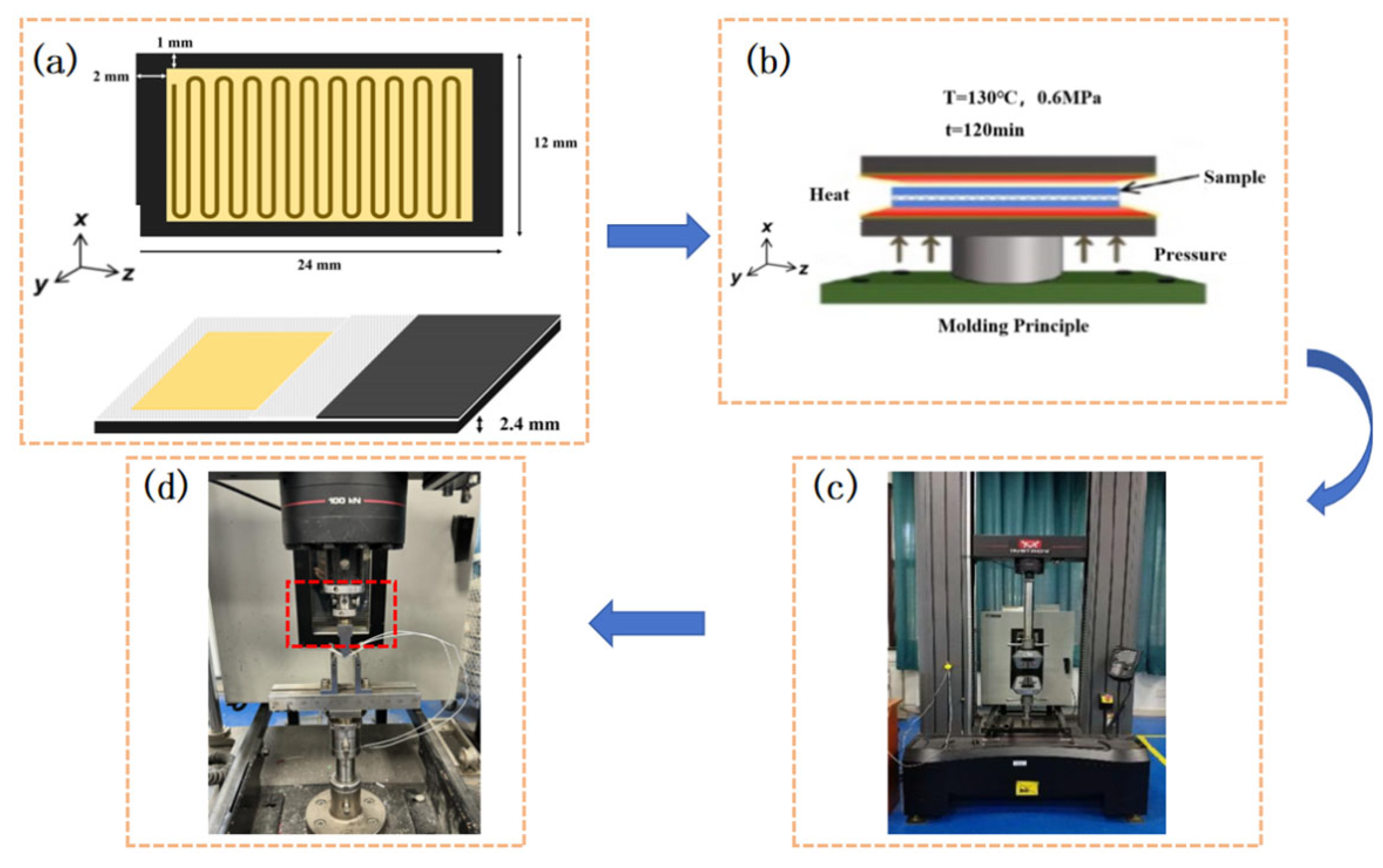
The testing system employed is a Universal Electronic Testing Machine (Instron-5982) manufactured by Instron (Norwood, MA, USA), with the following loading configuration: a span (L) of 5 h ± 0.3 mm (where h denotes specimen thickness), an upper loading nose radius of 5.0 ± 0.2 mm, a lower loading nose radius of 2.0 ± 0.2 mm, and a loading rate of 1.0 ± 0.2 mm/min. The specimen design includes dimensions of 24 mm (length) × 12 mm (width) × 2.4 mm (thickness), with a design basis of an electrothermal element to prepreg layer area ratio of 62% and a metal layer thickness of 4.5 mm. Each group consists of 10 parallel specimens.
(3)
Testing Equipment
An Instron-5982 universal electronic testing machine manufactured by Instron (Norwood, MA, USA)was utilized, featuring a span of L = 5 h ± 0.3 mm (where h is the sample thickness). The radii of the upper and lower loading heads were r1 = 5 ± 0.2 mm and r2 = 2 ± 0.2 mm, respectively. The loading rate was maintained at 1 ± 0.2 mm/min. A total of ten specimens were tested per group, and the average values were reported for the material properties. The specimen dimensions, determined based on the area ratio between the lip-section electrothermal elements and the prepreg layer (approximately 62%), and the lip-section metal thickness (~4.5 mm), were 24 mm × 12 mm × 2.4 mm, as depicted in Figure 3.
Interlaminar shear strength calculation formula [21]:
τ M = 3 4 × F b h  
where τ M is the interlaminar shear strength (MPa); F is the failure load or maximum load (N); b is the specimen width (mm); and h is the specimen thickness (mm).

3. Results and Discussion

3.1. Electrothermal Modeling and Performance Analysis

The primary performance metrics of anti-icing and de-icing components are predominantly encapsulated in two dimensions: the heating rate and electro-thermal conversion efficiency. These critical parameters are largely influenced by the resistivity and thermal conductivity properties of the heating materials, the spatial configuration of the heating elements, and the thickness and material characteristics of the insulating layers. These influences are quantitatively expressed through parameters such as interfacial thermal resistance, in-plane thermal conductivity, and electro-thermal conversion efficiency.
The electro-thermal conversion efficiency (η) is quantitatively defined as the ratio of thermal energy output to electrical energy input, calculated as follows [22]:
η = P t h e r m a l P e l e c t r i c a l = m · c p · Δ T V · I · t  
where m denotes mass (unit: kg); cp represents specific heat capacity (unit: J/(kg °C;)); ΔT indicates temperature rise; t is time; and V denotes voltage.
(1)
Static conditions
Static room-temperature power-on performance evaluations were conducted using a HYJ-500 power supply on two configurations: conventional separated (Sample 1) and functional–structural integration (Sample 2), both at 15 V. Metrics such as current, power, heating rate, electro-thermal conversion efficiency, and heating power density were systematically compiled and analyzed, as presented in Table 2.
The data reveal that the heating rate of Sample 2 exceeds that of Sample 1 by 49%, suggesting that the functional–structural integration design may enhance heat conduction or distribution. Furthermore, Sample 2 exhibits a higher electro-thermal conversion efficiency (67.93% compared to 63.13% for Sample 1), indicating reduced energy loss and more effective energy utilization. The current (0.61 A) and power (9.2 W) for Sample 2 are marginally lower than those for Sample 1, which may be attributed to variations in resistance arising from differences in structural design. Power density is indicative of the heating capacity per unit area. Sample 1 demonstrates a higher power density (515.63 W/m2) relative to Sample 2 (464.65 W/m2). Nonetheless, when evaluating the heating rate, Sample 2 achieves a more rapid temperature increase despite its lower power density, likely attributed to its optimized structural design.
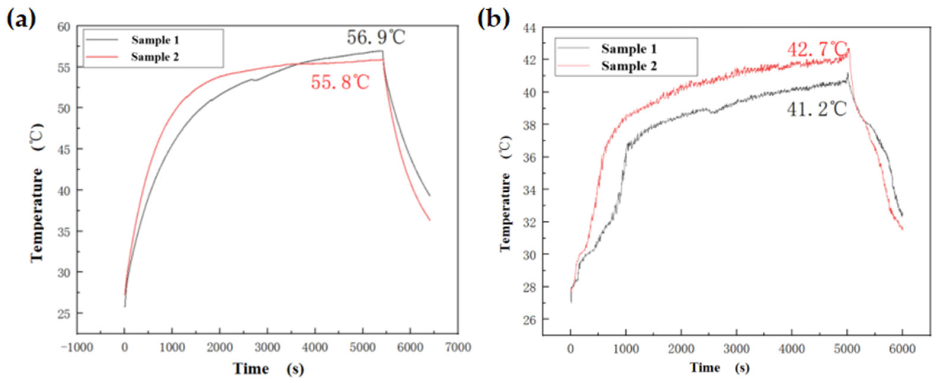
The experiments were conducted utilizing a multifunctional data acquisition instrument (model M300, produced by RIGOL Co., Suzhou, Jiangsu Province, China) to assess the temperature-rise curves on both the inner and outer surfaces of Samples 1 and 2, as illustrated in Figure 4. The experimental data presented in Figure 4a,b indicate that Sample 2 exhibits enhanced electrothermal performance: the heating rate increased by 49% (from 0.51 to 0.76 °C/min), electrothermal efficiency improved by 4.8%, and power consumption decreased by 7%. Additionally, temperature heating uniformity improved by 38%. In Sample 1, the heating layer was bonded to the matrix, resulting in localized poor contact that induced interfacial thermal resistance and compromised heating uniformity. In contrast, Sample 2 possesses an integrated structure that minimizes interfacial thermal resistance, thereby enabling more continuous heat conduction pathways and promoting uniform heat diffusion.
(2)
Low-temperature dynamic conditions
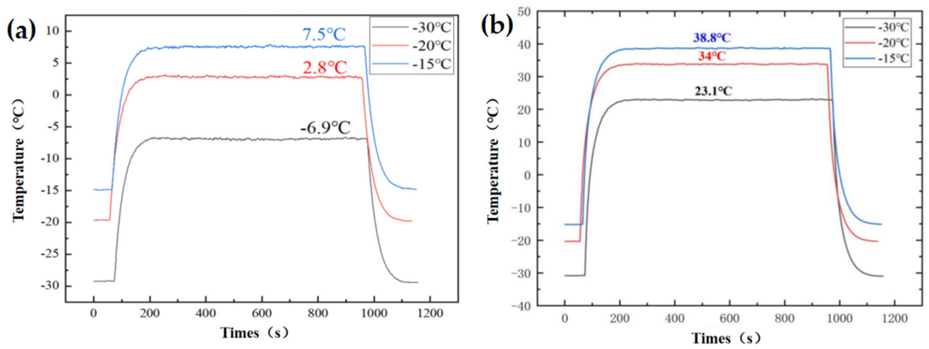
To assess the efficacy of Sample 1 and Sample 2 in preventing ice formation at low temperatures, dynamic anti-icing tests were performed on both samples under conditions of −15, −20, and −30 °C, with a wind speed of 20 m/s. The outcomes of these tests are detailed in Table 3 and Table 4.
The temperature-rise profiles of the inner and outer surfaces for Sample 1 and Sample 2 under low-temperature conditions were measured, as illustrated in Figure 5. An analysis of the low-temperature dynamic test data presented in Table 3 and Table 4 and Figure 5 indicates that both Sample 1 and Sample 2 exhibit comparable input power and heat flux density. As the ambient temperature decreases to −30 °C, the minimum surface temperature of Component 2 reaches 23.1 °C, remaining above the freezing point, whereas Component 1 registers a temperature of −6.9 °C, making it susceptible to icing. Component 2 demonstrates superior performance in maintaining surface temperature and preventing secondary icing. For Sample 1, the heating rate initially decreased and then increased (from 2.76 °C/min to 2.96 °C/min), while the efficiency continuously declined (from 67.24 to 66.16%). This behavior may be attributed to fluctuations in the thermal conductivity of the cladding material at low temperatures. Sample 2 achieved its peak heating rate at −20 °C (9.08 °C/min), with a slight decrease at −30 °C (8.95 °C/min). However, its efficiency remained stable above 75%, indicating enhanced adaptability to low-temperature conditions.
As illustrated in Figure 5, under extreme conditions of −30 °C and a wind speed of 20 m/s, Sample 2 demonstrated substantial advantages over Sample 1. Specifically, the heating rate of Sample 2 was 8.95 °C/min, significantly surpassing that of Sample 1, which was 2.96 °C/min, marking an improvement of 202%. This finding indicates that the integrated structure is capable of maintaining rapid heating under low-temperature and high-wind conditions, thereby facilitating faster anti-icing responses. Such characteristics render it particularly suitable for applications requiring rapid de-icing, such as in the aviation and wind power sectors. Furthermore, Sample 2 achieved an efficiency of 75.31%, exceeding that of Sample 1 (66.16%) by 9.15 percentage points, which corresponds to a relative improvement of 13.83%. This suggests superior energy utilization and reduced electrical waste. The advantage of Sample 2 remains consistent across various low-temperature conditions ranging from −15 to −30 °C, as indicated in Table 3, underscoring the robustness of the integrated design.
Sample 2, characterized by its integrated design, is more suitable for environments with extremely low temperatures and high wind speeds, such as the service environment of aircraft wings and wind turbine blades. This suitability is attributed to its rapid heating capabilities, high efficiency, and precise surface temperature control. In contrast, Sample 1, which employs a traditional bonded type design, demonstrates a marginally higher heat flux density but is hindered by slower heating and lower efficiency. Consequently, it may be more appropriate for static equipment where low response speed is acceptable. Enhancements in the traditional bonded design, particularly in reducing interfacial thermal resistance through methods such as thermal paste optimization or integrated encapsulation, are necessary to improve its dynamic performance in low-temperature conditions.
(3)
De-icing Effectiveness Evaluation
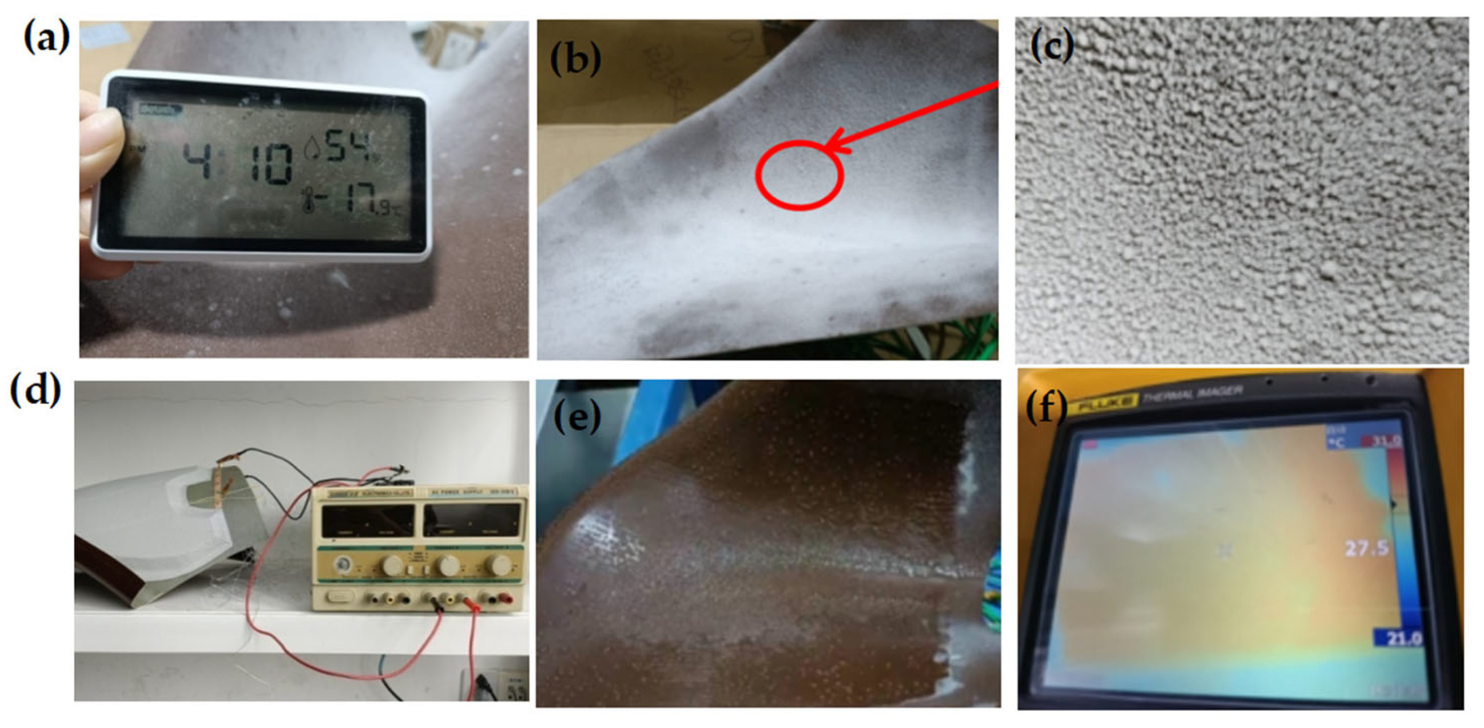
To further assess the anti-icing capability of the integrated functional–structural anti-icing/de-icing component, a de-icing effectiveness test was conducted under low-temperature conditions (−17.9 °C) with 54% ambient humidity. An ice layer with a thickness of 2.0 ± 0.1 mm was generated by sequentially spraying water mist onto the curved inlet test component.
As illustrated in Figure 6, the activation of the integrated functional–structural anti-icing/de-icing component with a 28 V power supply for a duration of 20 s resulted in remarkable de-icing efficacy. The 2 mm ice layer was entirely melted, achieving 100% area coverage without any residual ice crystals remaining on the surface, thereby demonstrating effective de-icing performance. Furthermore, surface temperature measurements were obtained using a thermal imager (refer to Figure 6f), which indicated an average surface temperature of 27.5 °C during the de-icing process. This temperature range is conducive to efficient ice melting while simultaneously mitigating the risk of thermal damage to the component.

3.2. Heat Transfer Path Analysis

Specimen 1 and Specimen 2 demonstrate distinct heat conduction pathways, as depicted in Figure 7. Specimen 2 underwent a hot-pressing process at 130 °C and 0.6 MPa for a duration of 2 h, effectively eliminating air bubbles within the epoxy resin layer and consequently shortening the heat conduction path from the heating element to the inner surface.
The synergistic optimization of thermal diffusivity and through-thickness thermal conductivity within the integrated structure minimizes edge heat loss, thereby facilitating more uniform and efficient heat transfer. Consequently, the enhanced electrothermal performance of Specimen 2 can be attributed to structural optimization. The integrated design obviates the necessity for traditional externally bonded encapsulation layers, thereby removing the adhesive layer, eradicating interfacial thermal resistance, shortening the heat conduction path, and enhancing interfacial heat transfer efficiency. This results in accelerated heating rates and improved electro-thermal conversion efficiency.

3.3. Interlaminar Mechanical Performance Evaluation

3.3.1. Interlaminar Mechanical Test Methods

To assess the degradation of interlaminar mechanical properties, accelerated aging tests were conducted within a temperature range of −30 to 80 °C, at a voltage of 36 V, and a wind speed of 60 m/s. Short beam shear tests were performed on specimens subjected to 10,000, 15,000, and 20,000 electrothermal cycles.
The impact of electrothermal cycling on the interlaminar mechanical properties of composite materials was further examined using three-point bending tests, in accordance with the ISO 14130 Standard. The testing process was characterized by three distinct stages: the initial debonding stage, the complete debonding stage, and the final failure stage. Load-displacement curves, obtained from the Instron-5982 testing machine, manufactured by Instron (Norwood, MA, USA), indicated that untreated specimens exhibited an initial debonding load of 5122 ± 35 N, a complete debonding load of 6781 ± 43 N, and an ultimate failure load of 8752 ± 62 N.
As illustrated in Figure 8, an increase in load induces debonding between the GFRP and the metal substrate, resulting in the formation of a gap, as depicted in Figure 8a. Complete debonding is observed between the GFRP and the metal substrate, with the left side of the GFRP specimen exhibiting upward warping, as shown in Figure 8b. As the bending pressure intensifies, further loading leads to the fracture of the GFRP and its complete separation from the metal substrate, ultimately culminating in the overall bending fracture failure of the metal plate, as presented in Figure 8c.

3.3.2. Interlaminar Mechanical Testing Results and Discussion

Shear tests on short beams were performed on specimens exposed to 10,000, 15,000, and 20,000 electrothermal cycles to assess the degradation of interlaminar mechanical properties. The results of these tests are presented in Table 5. Table 6 provides a comparative analysis of the baseline mechanical properties between the traditional discrete structure (Specimen 1) and the functionally integrated structure (Specimen 2).
The experimental findings presented in Table 5 reveal that the anti-icing/de-icing component experienced a 61.39% reduction in initial debonding strength following 10,000 electrothermal cycles. This reduction increased to 84.68% after 20,000 cycles. As illustrated in Table 6, the functionally integrated specimen exhibits considerable advantages over the conventional adhesively bonded configuration, with a 30.5% enhancement in interlaminar shear strength.
In comparison to untreated composite specimens, those subjected to electrothermal cycling demonstrated significantly earlier onset and completion of debonding, accompanied by a pronounced reduction in interlaminar shear strength. These observations suggest that electrothermal cycling can induce premature damage initiation and progressive degradation of mechanical properties, culminating in a substantial decline in interlaminar shear strength (ILSS).
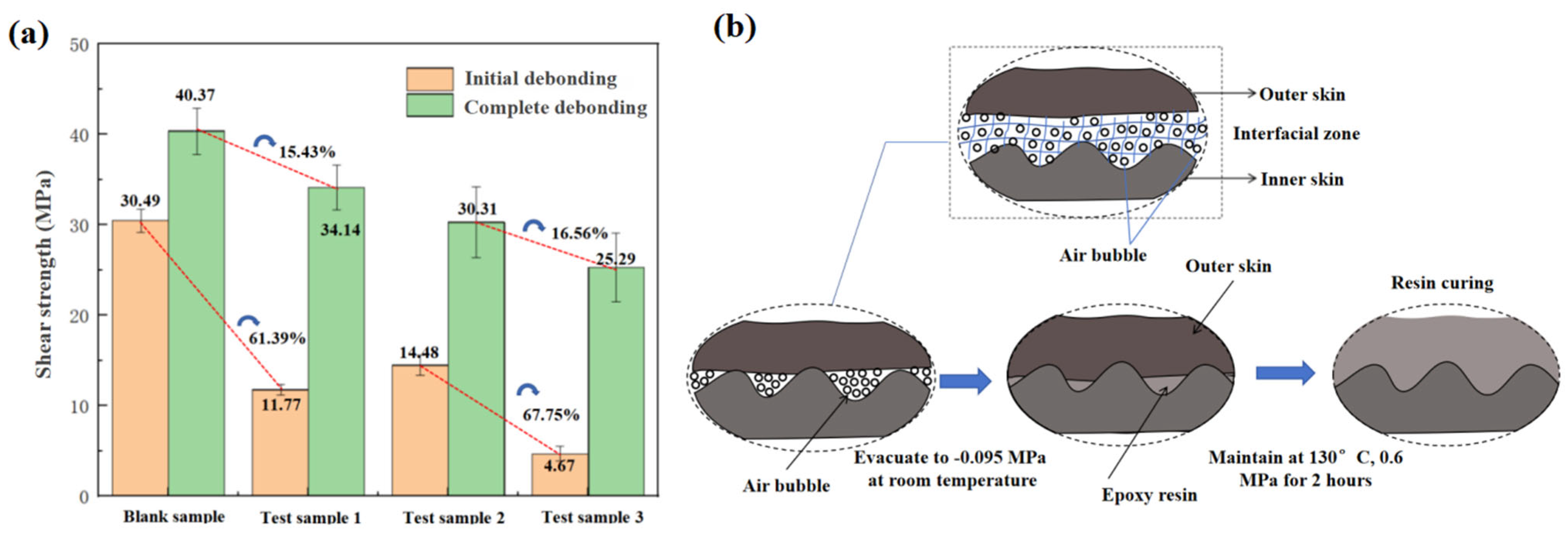
As illustrated in Figure 9a, the shear strength at the onset of debonding for specimens subjected to three electrothermal cycling tests exhibited reductions of 61.39% (after 10,000 cycles), 52.51% (after 15,000 cycles), and 84.68% (after 20,000 cycles) when compared to untreated specimens. Upon complete debonding, the shear strength further decreased by 15.43% (after 10,000 cycles), 24.91% (after 15,000 cycles), and 37.35% (after 20,000 cycles). The most pronounced degradation of interlaminar mechanical properties was observed following 20,000 cycles, substantiating that cumulative electrothermal fatigue is the principal factor contributing to the deterioration of mechanical performance. Two degradation mechanisms were identified in the de-icing component during electrothermal cycling: firstly, the physical aging of the resin matrix in high-temperature environments diminishes the fiber-matrix interface strength; secondly, the formation of microcracks at the metal-composite interface compromises the bonding strength between fiber bundles and the matrix.
Within the cycle interval of 10,000 to 15,000 cycles, a deceleration in the rate of strength reduction was observed, decreasing from 61.39 to 52.51%. This phenomenon is associated with the secondary curing of the resin during heating and the release of internal stress, which can be attributed to the physical aging of the epoxy resin. The observed trend is consistent with findings in the literature [23], which demonstrate non-monotonic characteristics in the degradation of interlaminar shear strength under electrothermal conditions, which is in contrast to traditional linear degradation models. As the cycle count increased further to the range of 15,000 to 20,000 cycles, significant debonding occurred at the matrix–fiber interface, resulting in a substantial decrease in strength to 84.68%.
Within the 10,000 to 15,000 cycle interval, a deceleration in the rate of strength reduction was observed. For complex curved structures, such as aircraft wings, traditional adhesive bonding processes are susceptible to the formation of porosity defects, which significantly compromise bonding strength. In contrast, the embedded co-curing approach with vacuum processing (at 130 °C, 0.6 MPa, for 2 h), as illustrated in Figure 9b, facilitates uniform curing of metal layers with resin particles. This method enhances interlaminar thermal conductivity, eliminates porosity defects, and allows the integrated structure to achieve superior comprehensive electro-thermal–mechanical performance. The integrated structure exhibits significantly improved mechanical properties, with a 30.5% relative increase in interlaminar shear strength, effectively delaying damage propagation.
The embedded co-curing technology utilized in this study addresses the limitations associated with conventional adhesive bonding by optimizing stress distribution and enhancing damage tolerance. In applications involving extreme environments, such as aerospace or wind turbine blades, integrated manufacturing processes—such as the combination of co-curing with anti-icing functionalities—exhibit significant advantages in high-reliability anti-icing and de-icing engineering applications.

3.4. Thermo-Electro–Mechanical Coupling Analysis

3.4.1. Microstructural Characterization

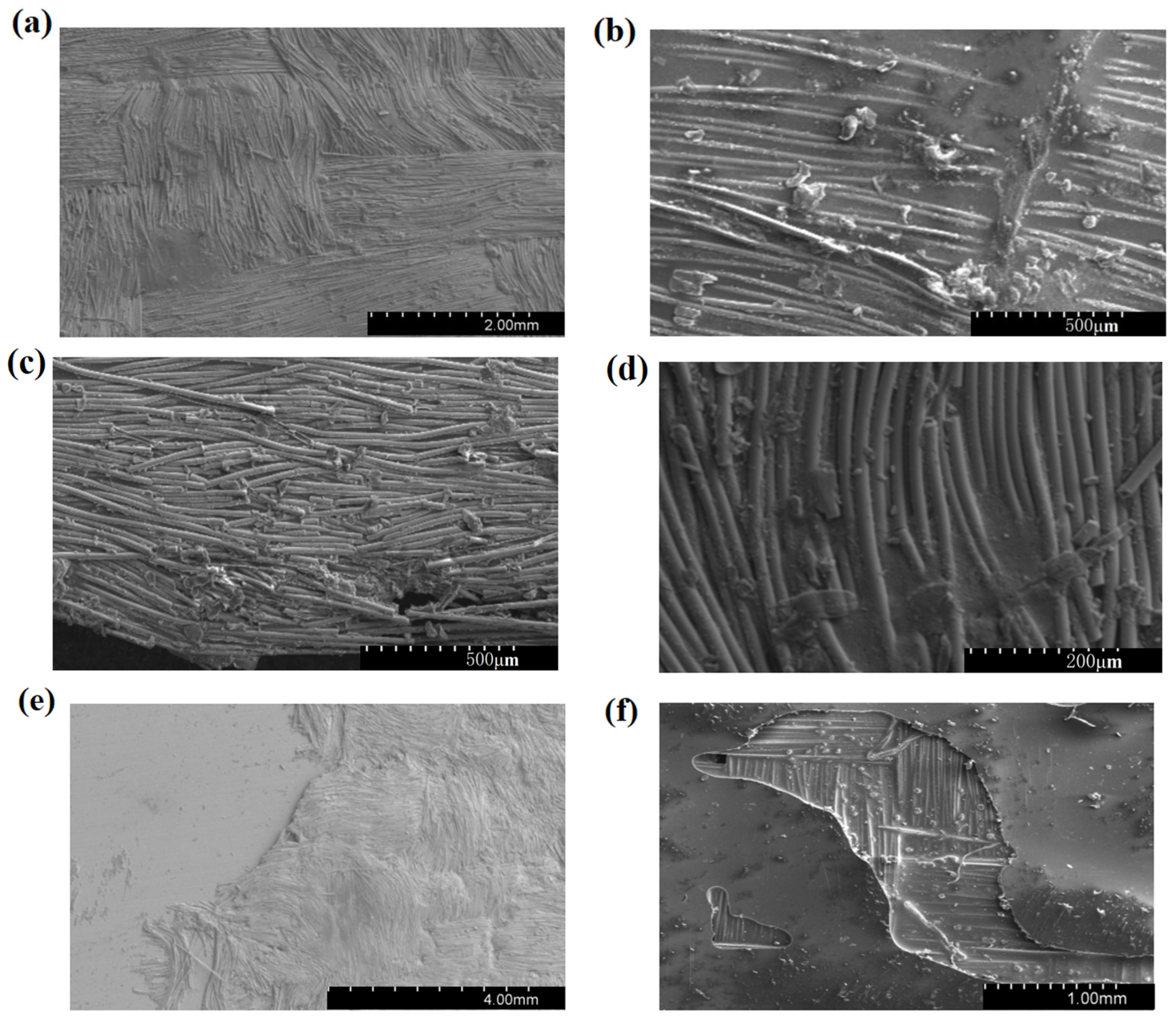
A comparative analysis was performed utilizing a Hitachi S-3400N scanning electron microscope, manufactured by Hitachi High-Technologies Corporation (Tokyo, Japan), operating at an accelerating voltage of 15 kV and a working distance of 10 mm to examine differences between pristine specimens and those subjected to 20,000 electrothermal cycles. The pristine specimens displayed characteristics indicative of optimal fiber–resin bonding, characterized by completely coated glass fiber surfaces with a uniform resin layer. Conversely, at the metal–composite interface, the specimens exhibited evidence of partial fiber damage, fracture, and interfacial debonding. As illustrated in Figure 10, resin exposure was noted at the bonding surface between the heating film and the metal, revealing a smooth fiber–resin interface alongside localized fiber fractures, resin fragments, and interfacial debonding phenomena. These observations suggest that high-temperature thermal stress induces significant resin damage, thereby compromising the interlaminar bonding strength. The experimental data further reveal that, following electrothermal cycling, the fiber–resin interfacial bonding strength of the specimens is markedly reduced compared to the control group, underscoring the substantial impact of electrical effects in electrothermal coupling on material performance. Micro-morphology analysis of anti-/de-icing specimens after electrothermal cycling revealed that thermal stress-induced cracking is the primary cause of interfacial strength degradation, with Joule heating within heating elements exacerbating interface damage; resin–fiber delamination and debonding constitute the primary failure modes, explaining the macroscopic mechanical performance degradation observed in Section 3.3.

3.4.2. Interfacial Constitutive Modeling

When UAVs perform multiple extended flight missions, the electrothermal de-icing system inevitably undergoes repeated internal thermal stress. Differences in coefficients of thermal expansion between materials lead to interlaminar stress concentration, resulting in microcrack damage and resin physical aging under cyclic loading. Therefore, to investigate the influence of internal thermal stress on the mechanical properties of interlaminar strength, this paper establishes a model of functional–structural integration. It then develops a stress mismatch model that arises during the heating or cooling of heating units. This model holds significant engineering importance for strength prediction and lifespan assessment of electrothermal de-icing units featuring functional–structural integration.
Addressing the thin-layer characteristics of the anti-/de-icing functional interface layer, the adhesive layer employs a cohesive zone model [24] to quantify the initiation and propagation behavior of cracks at the metal–fiber interface (Figure 11a). Based on thermoelasticity theory, this study derives an analytical expression for thermal expansion mismatch stress in heterogeneous materials, thereby obtaining a thermal stress mismatch model for integrated functional–structural anti-/de-icing systems. By characterizing stress distribution during thermal cycling of heating units, the engineering application of strength prediction and lifespan assessment for integrated anti-icing structures was achieved.
Before the anti-icing/de-icing functional–structural integrated laminate reaches its maximum strength, the constitutive relationship of the cohesive elements [27] is as follows:
τ = K 0 δ ,                                           0 δ δ 0 1 D K 0 δ ,               0 δ δ 0 0 ,                                         0 δ f
D =                                                                         0 ,                                                                                       0 δ δ 0 1 δ 0 δ 1 1 e x p α δ δ 0 δ f δ 0 1 e x p ( a )               δ 0 δ δ f                                                                       1 ,                                                                                         δ > δ f
In the formula, K 0 is the initial stiffness of the interface before delamination failure in N/mm; δ is the separation displacement of the upper and lower surfaces caused by thermal stress; δ 0 is the interface opening displacement when the traction force reaches the maximum value; δ f is the interface opening displacement at final failure in mm; D is the damage variable of the adhesive layer in the softening stage; and G represents the interlaminar fracture toughness.
The thermal elastic mismatch stress equation for the functionally–structurally integrated component is established as follows:
σ = E · Δ α · Δ Τ
Here, Δα represents the difference in coefficients of thermal expansion (CTE), E denotes Young’s modulus, and ΔT corresponds to the temperature variation. This theoretical framework offers critical engineering guidance for the durability design of functionally–structurally integrated anti-icing/de-icing components in aerospace applications.
Based on the constitutive model, a stress mismatch model was established to quantify the thermal stress mismatch arising from the CTE discrepancy between metallic materials and composite materials during heating or cooling processes [28]. The fundamental equations of thermoelastic mechanics for each material in the functionally structurally integrated system were formulated.
ε t o t a l = ε m e c h + ε t h e r m a l
In the formula, ε m e c h is the mechanical strain, ε t h e r m a l is the thermal strain, and ε t o t a l is the total strain. Assuming is an isotropic material, the total strain ( ε t o t a l ) caused by temperature change includes mechanical strain (   ε m e c h   ) and thermal strain ( ε t h e r m a l ).
The thermal strain ( ε t h e r m a l ) is determined by the expansion coefficient ( α ) and temperature variation ( Δ T ), as given by the following formula:
ε t h e r m a l = α · Δ T
In the formula, α is the coefficient of thermal expansion (CTE) (in K−1) and Δ T is the temperature variation (in K).
Assuming that the metal layer and the composite layer are fully bonded with no slip at the interface, the transverse strains of the two materials must be coordinated as follows:
ε t r a n s v e r s e m e t a l = ε t r a n s v e r s e c o m p o s i t e
Substitute into the total strain expression:
ε m e c h m e t a l + α m e t a l Δ T = ε m e c h c o m p o s i t e + α c o m p o s i t e Δ T
Since the interface mainly bears uniaxial stress (σ), the transverse stress component is neglected, which can be simplified as follows:
ε m e t a l = σ E ( 1 υ )
According to Hooke’s Law, substituting the expression for mechanical strain into the strain compatibility equation, the interlaminar stress values for different materials are obtained.
σ = E α 1 α 2 ( 1 ν ) Δ T
In the formula: E is the elastic modulus of the material, ν is Poisson’s ratio, α are the thermal expansion coefficients of the two materials, and ΔT is the temperature variation. It is assumed that the two materials are tightly bonded and cannot expand or contract freely when the temperature changes, thus generating mutually constraining stresses.
During service, integrated functional–structural anti-icing/de-icing components develop substantial thermal residual stresses and strains as a result of mismatches in the coefficients of thermal expansion between layers subjected to temperature fluctuations. This phenomenon can lead to damage, including interlaminar delamination and interfacial debonding. In particular, laminates that incorporate metallic heating layers are susceptible to accelerated damage progression due to thermo-mechanical coupling effects under thermal cycling conditions.
This study utilizes the Abaqus (2022) finite element software to investigate the thermal fatigue model of an integrated functional–structural anti-icing/de-icing heating unit. The model employs 8-node coupled thermal-displacement elements, while cohesive elements are used to simulate interlaminar interface behavior. Progressive failure and fatigue damage evolution are incorporated through a USDFLD subroutine. The damage variable (D) for the cohesive elements is dynamically updated based on the cycle count and stress level, with complete interfacial debonding occurring when D reaches or exceeds 1. The simulation analysis focuses on the thermal residual stress and strain distributions within a five-layer composite laminate (comprising GFRP, polyimide, nichrome alloy, polyimide, and GFRP) subjected to temperature variation (ΔT = 100 °C) and thermal fatigue cycling, elucidating its evolution law and damage mechanisms.
The heating unit employs this five-layer composite material laminate, with the nichrome alloy serving as the intermediate heating element, as depicted in Figure 12a. The material parameters for each layer are comprehensively detailed in Table 7.
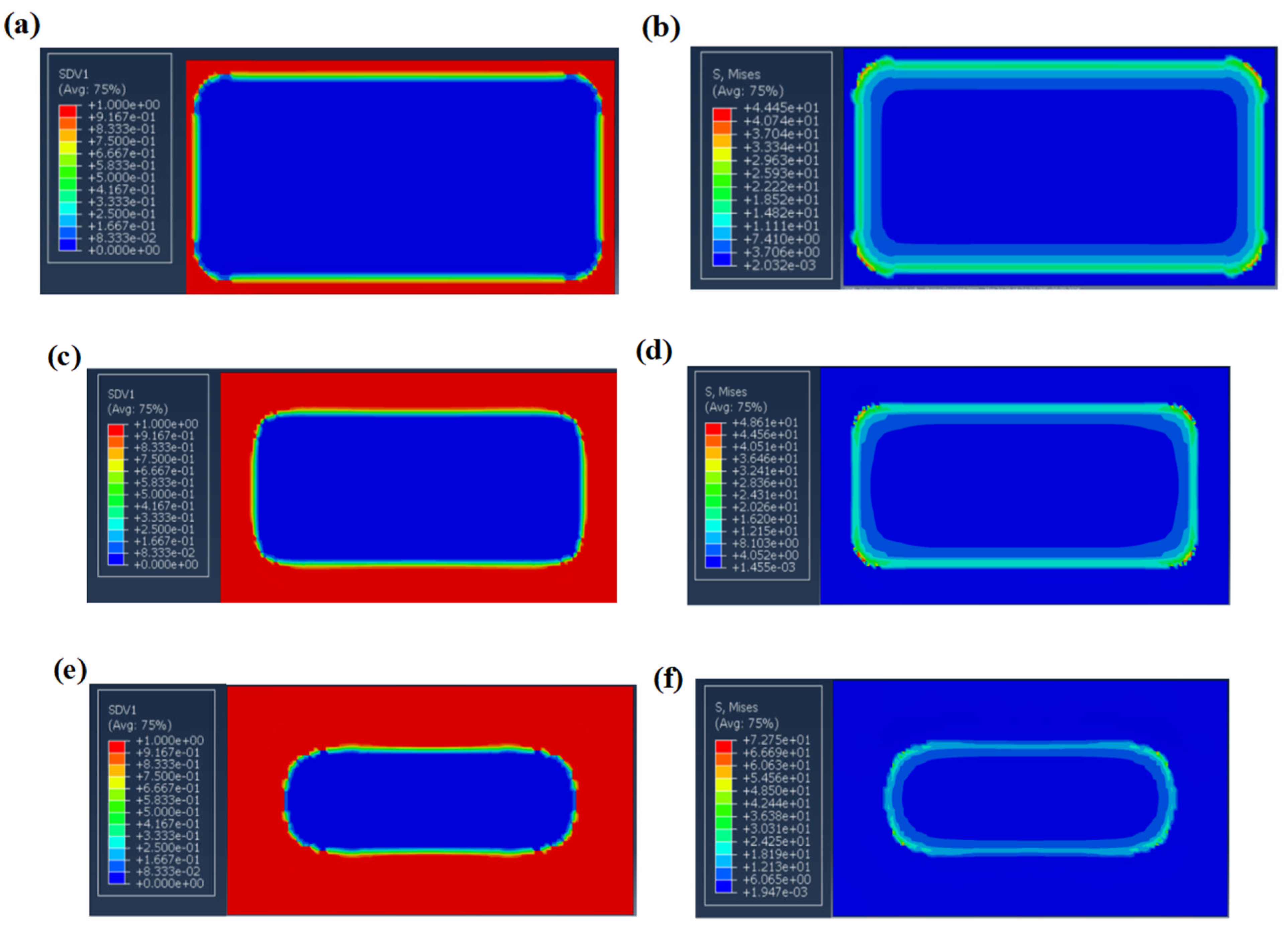
Figure 12b illustrates the initial condition at 20 °C, where the maximum stress is observed at the interface between the nichrome alloy and the polyimide. This stress arises due to the substantial disparity in their coefficients of thermal expansion (CTE), with the nichrome alloy exhibiting a CTE of 16 × 10−6/°C and the polyimide a CTE of 50 × 10−6/°C. Consequently, temperature fluctuations induce tensile stress at the interface. The stress levels in the peripheral areas surpass those in the central regions, with thermal residual strain predominantly influenced by thermal strain. Figure 13a demonstrates that after 10,000 heating cycles, cohesive unit damage is primarily concentrated at the upper interface of the nichrome alloy, adjacent to the upper polyimide layer. At this juncture, the interfacial stiffness decreases by approximately 20%, although no macroscopic debonding is observed. The amplitude of thermal residual stress increases by 10% compared to the initial cycles, attributed to stress redistribution resulting from damage. Figure 13c,e depict the stable propagation of thermal fatigue damage after 15,000 and 20,000 cycles, respectively. The interfacial area of failed units expands (D ≈ 0.6–0.8), with localized stress concentrations emerging in peripheral regions. The interface between the nichrome alloy and polyimide serves as the zone of stress concentration. Failure propagates radially from the periphery toward the central region. The peak interfacial stress at the metal–composite interface reached 73 MPa, surpassing the yield strength of the epoxy resin (65 MPa), resulting in interface delamination. Thermal fatigue cycling accelerated the progressive failure of cohesive elements, with the interfacial debonding area reaching 60% after 20,000 cycles, significantly compromising the interlaminar mechanical properties of the laminate.

3.4.3. Interfacial Degradation Mechanisms

Interlaminar delamination failure represents the primary failure mode in functionally integrated anti-icing/de-icing components. The critical factor contributing to structural failure is weak interfacial bonding at both the metal/fiber interlayer and fiber ply interfaces, with macroscopic mechanical properties being directly linked to interfacial characteristics [29]. Electrothermal fatigue testing and micro-morphology analysis revealed that the interfacial bonding in integrated functional–structural anti-icing/de-icing systems exhibits distinct characteristics: the fiber layers form chemical/molecular bonds through resin curing, whereas the metal–fiber interface predominantly relies on mechanical interlocking. Weakness at the metal–fiber interfaces can result in delamination, thereby compromising the overall stiffness and strength of the aircraft [30,31].
Based on the results of thermal fatigue tests conducted on anti-icing/de-icing specimens, this study elucidates that the integrated functional–structural anti-icing/de-icing system undergoes a three-stage inter-laminar damage degradation process: elastic deformation, plastic accumulation, and viscous failure. When the interfacial shear strength surpasses that of the resin matrix, the shear forces exerted by fractured fibers on adjacent fibers induce plastic damage within the resin, ultimately leading to failure. The progression of damage within the resin can be categorized into three distinct stages: initial damage characterized by elastic deformation, stable propagation marked by plastic hardening, and accelerated failure associated with slip friction, as illustrated in Figure 14.
It is postulated that under cyclic thermal stress conditions, continuous damage accumulation occurs within the microcracks of integrated functional–structural anti-icing/de-icing components, leading to progressive propagation with an increasing number of cycles. The degradation of stiffness in composite materials subjected to thermal cycling primarily arises from three distinct types of damage: initial interfacial damage (Stage I), matrix fatigue damage (Stage II), and coupled matrix damage (Stage III). Consequently, the total damage variable can be expressed as D ( N ) = D 1 ( N ) + D 2 ( N ) + D 3 ( N ) , where D 1 represents initial interfacial damage, D 2 denotes matrix fatigue damage, D 3 signifies coupled damage, and N indicates the thermal cycle count. Based on these three types of damage, a mechanical performance degradation model under stress fatigue for functionally–structurally integrated anti-/de-icing components is developed as follows:
M n = M 0 ( 1 D n )
M n is the current mechanical property after n electrothermal cycles (in MPa); M 0 is the initial mechanical property index of the material (in MPa), i.e., the property value without damage (in MPa); n is the number of electrothermal cycles; and D(n) is the damage variable (0 ≤ D(n) ≤ 1), which characterizes the degree of performance degradation.
Stage I: Initial damage stage
D n = k 1 · N
Stage I is a stage of linear damage accumulation (microcrack initiation). In this stage, microcracks start to initiate in the resin matrix of the functionally–structurally integrated component, the interfacial shear strength decreases, and the interlaminar strength exhibits linear damage characteristics. It is assumed that the critical condition is that the interlaminar stress work generated by thermal cycles is equal to the interfacial fracture toughness ( G c is an inherent property of the material, with the unit of J/m2).
In thermal cycles, interlaminar thermal stress ( σ int ) is caused by temperature difference ( Δ T ) and mismatched thermal expansion of materials.
σ int = E int Δ α Δ T
In the formula, E int is the equivalent elastic modulus of the interface, Δ α is the difference between thermal expansion coefficients, and Δ T is the temperature difference.
According to the cohesive zone model and interface fracture criterion, the evolution of interface debonding damage ( D 1 ) with the number of cycles satisfies the following:
d D 1 d N = k 1 σ int G c
For initial damage, integrating Equation (14) yields the following:
D 1 ( N ) = k 1 ( E int Δ α Δ T G c ) N
The linear relationship between stiffness degradation and in the initial stage (stiffness) can be obtained through linear regression as follows:
k 1 = Δ E / E 0 N G c E int Δ α Δ T
where   Δ E is the stiffness degradation amount; E 0 is the initial stiffness of the material; E int is the equivalent elastic modulus of the interface; N is the number of thermal cycles; Δ α is the mismatch amount of the thermal expansion coefficients of the materials; Δ T is the temperature difference range of thermal cycles; and G c is the interfacial fracture toughness. In the current stage, through the electrothermal cycle experiment ( 0 < N 5000 ), the shear strength attenuation rate is measured, and the linear fitting gives 4.0 × 10⁻⁵.
Stage II is a period of stable propagation, characterized by power function damage.
D n = D 1 + k 2 · ( N N 0 ) m
where N is the current number of loading cycles and N 0 is the number of loading cycles completed in the previous stage. Stage II is a period of damage accumulation (extension of interfacial debonding) for the functionally–structurally integrated component. During this stage, the debonded area at the fiber–resin interface increases, and the damage rate accelerates as the defect density rises. Debonding occurs at the fiber–resin interface of the functionally–structurally integrated component, leading to interfacial debonding and delamination.
Based on the power–law model of fatigue accumulation (phenomenological theory) and with reference to the Corten–Dolan model, a power function relationship between the number of cycles and damage of matrix microcracks is established.
D 2 ( N ) = k 2 N m
In the formula, m is the acceleration factor and k 2 is the matrix fatigue sensitivity coefficient. The fatigue limit of the matrix σ m , f (the critical stress corresponding to the number of cycles) satisfies the following:
σ m , f = σ m , 0 N f 1 / m
where σ m , 0 is the static strength of the matrix and σ m = E m α m Δ T is the stress borne by the matrix during thermal cycles. When σ m > σ m , f , the damage accelerates.
k 2 = σ m σ m , 0 m 1 N f
Taking the logarithm of the equation, through logarithmic linear regression (least square method) of the experimental data, m and l n k 2 can be separated, and then:
k 2 = e x p l n ( D 2 / N m )
In the formula, k 2 is the proportional coefficient and m is the power exponent (reflecting the degree of damage acceleration). By fitting the experimental data in the range of 5000 < n ≤ 15,000, using the least square method, m = 0.7 and k2 = 3.41×10⁻⁴ are determined.
Stage III: Coupled accelerated failure stage:
D n = 1 ( 1 D 2 ) · e k 3 · ( N N 0 )
where N is the current number of loading cycles and N 0 is the number of loading cycles completed in the previous stage. This stage is an exponential damage accumulation period for the functionally–structurally integrated component. Due to the stress concentration effect, the interfacial damage grows exponentially. Large-area debonding occurs at the interlaminar interface of the functionally–structurally integrated component, resulting in attenuation of interlaminar shear strength and showing an exponential degradation trend.
According to the damage coupling effect theory, interfacial debonding will lead to an increase in the matrix stress concentration factor. Therefore, D 3 for coupling damage, the product term of D 1 and D 2 , needs to be considered:
D 3 ( N ) = k 3 D 1 ( N ) D 2 ( N )
Substituting the expressions for D 1 and D 2 , and substituting the equation into it, we obtain the following:
D 3 ( N ) = k 3 · k 1 · k 2 · E int · Δ α · Δ T     G c · N m + 1
This stage of coupled damage exhibits strong nonlinearity, which needs to be solved by minimizing the residual between the experimental data (stiffness degradation curve) and the model’s predicted values. The Levenberg–Marquardt algorithm is adopted, with the objective function as follows:
min i = 1 n E exp ( N i )   -   E 0 ( 1   -   D 1   -   D 2   -   D 3 ) 2
The solved theoretical form is the coupled damage increment k 3 interfacial damage and matrix damage.
k 3 = D 3 D 1 D 2
In the formula, is the proportional coefficient. According to the exponential decay characteristic of the accelerated failure stage, k3 = 2.49 × 10⁻⁴ is obtained through solving with boundary conditions. In this paper, k 1 , k 2 and k 3 are estimated by engineering test fitting, which still needs further verification in engineering practice.
Figure 14 illustrates the progression of damage evolution in the heating layer under electrothermal cycling, which occurs in three distinct stages. Initially, during the elastic stage, reversible deformation is observed in the heating component, accompanied by the formation of minor internal cracks. As the process advances to the plastic hardening stage, stress-induced damage accumulates within the fibers due to repeated power-on and power-off cycles. In the final slip-friction stage, when the operating temperature surpasses the glass transition temperature (Tg) of the resin matrix, the resin undergoes significant softening. This softening exacerbates the delamination phenomenon, leading to a marked reduction in interlaminar shear strength. Ultimately, complete delamination failure occurs at the interface between the metal and fiber layers of the heating component.
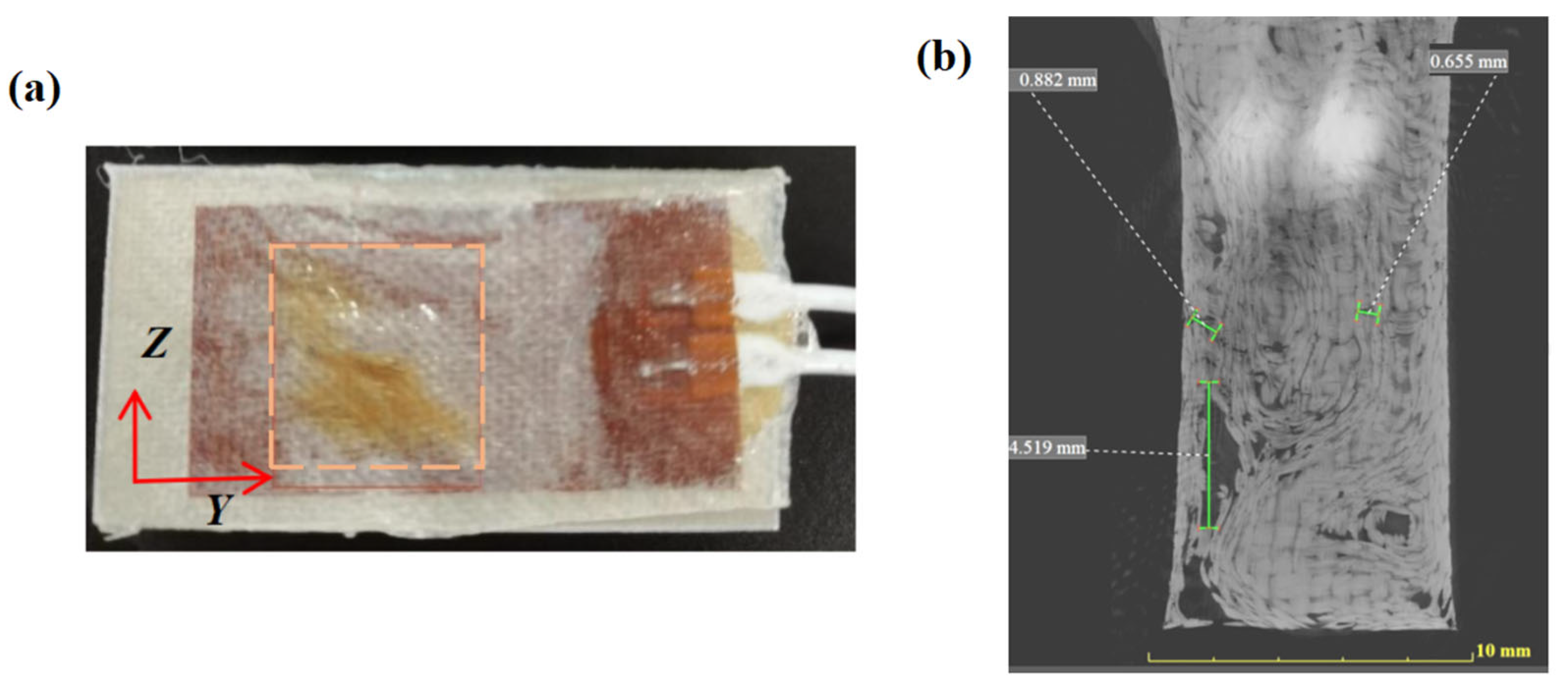
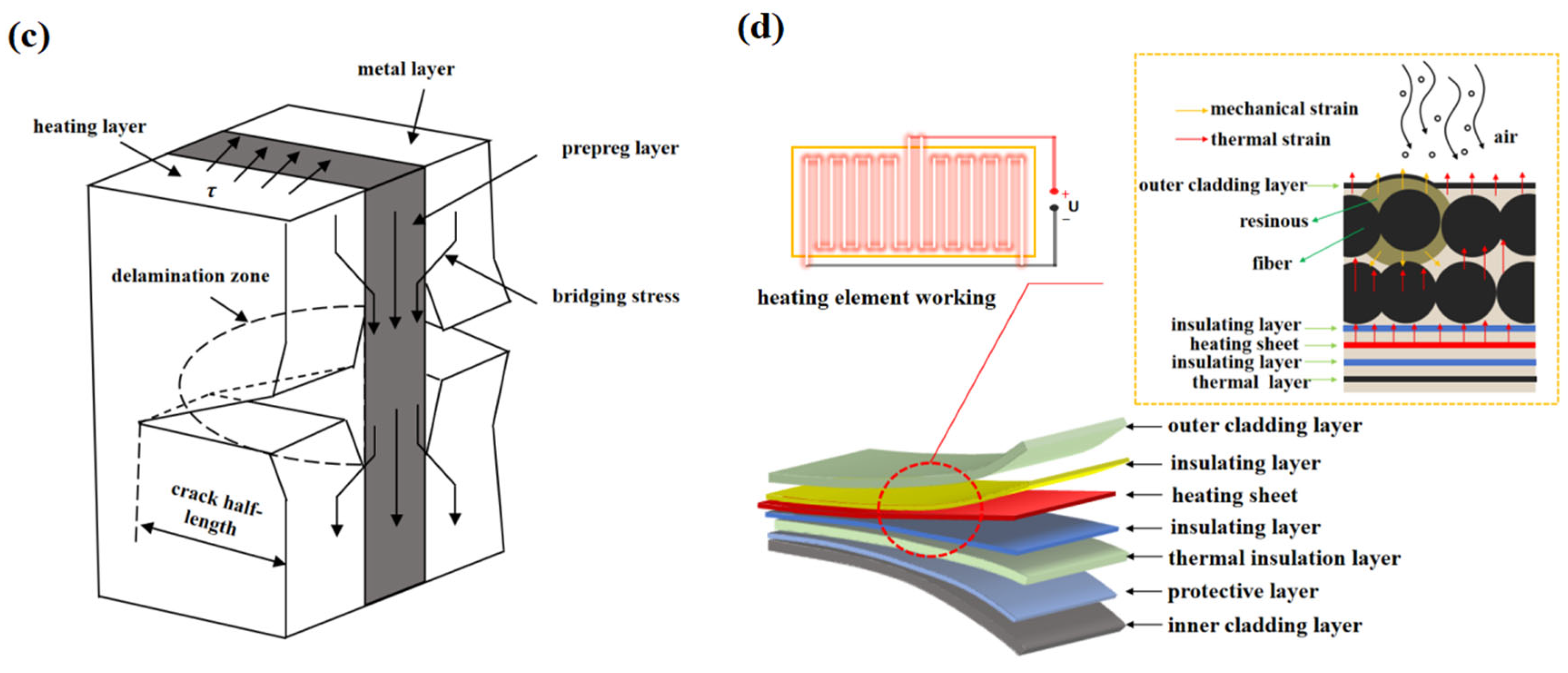
As illustrated in Figure 15a, the electro-thermal coupling experiment demonstrates that current conduction between adjacent fibers results in Joule heating. This thermal energy propagates through the fiber–resin interface, leading to the expansion of the resin. During the cooling phase, residual thermal stresses, which accumulate as the resin undergoes recuring (Figure 15b), exacerbate interfacial gaps and diminish bonding strength. Concurrently, the co-curing process under hot pressing conditions, involving a temperature reduction from 130 °C to ambient levels, induces residual stresses due to the disparity in thermal expansion coefficients between the composite material and the metal layer. These localized stress concentrations precipitate interfacial debonding.
Figure 15c,d demonstrate that the integrated functional–structural anti-icing/de-icing component induces bridging stress at the heating interface upon activation. Progressive crack propagation is observed with an increase in cycle counts, while localized stress concentrations resulting from prolonged electrothermal cycling contribute to damage accumulation. This process ultimately diminishes interlaminar fracture toughness, culminating in extensive debonding and delamination.
The underlying mechanisms of electrothermally induced mechanical degradation involve multiple synergistic effects, including the physical aging of the resin, thermal expansion mismatch, and cyclic stress damage. Our experimental measurements demonstrate that the synergistic interaction of temperature and current during operation leads to epoxy resin embrittlement, exacerbates stress concentration at metal–fiber interfaces, and triggers anisotropic thermal expansion, with the thermal expansion coefficient mismatch reaching 12.7 ± 0.8 × 10⁻⁶ K−1. Cyclic thermal shock progressively compromises interface integrity through irreversible microcrack formation and accelerated damage accumulation during late-stage failure. After 20,000 cycles, the interlaminar shear strength (ILSS) decreases by 83.2%.
The degradation of mechanical performance in integrated functional–structural anti-icing/de-icing systems, attributed to electro-thermal coupling, is driven by the synergistic interaction of several factors, including the physical aging of the resin, thermal expansion mismatch, and cyclic stress damage. During the operation of the heating layer, the combined effects of internal temperature and electrical current lead to the embrittlement of the epoxy resin. Additionally, differences in the coefficients of thermal expansion at the metal–fiber interfaces intensify stress concentration and thermal expansion phenomena. Repeated thermal cycling progressively compromises interface integrity through the formation of irreversible micro-cracks. In the accelerated failure stages, this process results in a marked degradation of interlaminar mechanical properties, partial interfacial debonding, and macroscopic delamination within the integrated functional–structural components.
Drawing upon the previously discussed electro-thermal coupling test results, it is imperative to develop thermally compatible interface materials through innovative design strategies. Concurrently, the manufacturing process necessitates the optimization of hot-pressing parameters to augment the mechanical and thermal shock absorption capabilities. This approach aims to enhance the durability of integrated functional structures when subjected to thermo-mechanical coupled loads.

4. Conclusions

This study presents the development of an integrated anti-/de-icing component that combines electro-thermal functionality with structural load-bearing capabilities into a single entity. This design is particularly well-suited for small unmanned aerial vehicles, addressing their needs for lightweight and low-energy active de-icing solutions. Experimental results indicate that this component significantly enhances heating performance compared to traditional bonded structures. The study also reveals that electrothermal cycling substantially reduces interlaminar shear strength. Microstructural analysis suggests that the accumulation of thermal fatigue stress is the primary contributing factor to this reduction. The embedded hot-press co-curing encapsulation process is crucial in determining electrothermal performance by affecting interfacial heat transfer efficiency. Nonetheless, the degradation mechanisms of interlaminar strength under electro-thermal–mechanical multi-field coupling warrant further comprehensive investigation. The existing thermal mismatch stress model exhibits specific limitations, particularly in its inability to adequately address anisotropic damage within composite materials.
Future research endeavors should aim to elucidate the mechanisms underlying interlaminar degradation under multi-field coupling conditions and to develop predictive models for material lifespan. As advancements in novel materials continue, the development of interface enhancement technologies, such as plasma activation and nanocoupling agents for anti-icing and de-icing functional interfaces, will be crucial in further mitigating the effects of thermal fatigue accumulation. These prospective advancements are anticipated to offer highly reliable solutions for the anti-icing and de-icing applications of unmanned aerial vehicles (UAVs) operating in extreme environments.

Author Contributions

N.D.: supervision, methodology, and conceptualization; Y.C.: writing—original draft, visualization, and formal analysis; C.H.: methodology, data curation, and writing—review and editing. All authors have read and agreed to the published version of the manuscript.

Funding

This research was funded by National Natural Science Foundation of China (Grant No. 52275255) and Talent Foundation of Dongguan City, China (Grant No. 24L3071E111).

Data Availability Statement

The original contributions presented in this study are included in the article. Further inquiries can be directed to the corresponding authors.

Conflicts of Interest

Authors Yanchao Cui was employed by the company Tianjin Aviation Electro-Mechanical Co., Ltd. The remaining authors declare that the research was conducted in the absence of any commercial or financial relationships that could be construed as a potential conflict of interest.

References

  1. Cao, Y.; Tan, W.; Wu, Z. Aircraft icing: An ongoing threat to aviation safety. Aerosp. Sci. Technol. 2018, 75, 353–385. [Google Scholar] [CrossRef]
  2. Lynch, F.T.; Khodadoust, A. Effects of ice accretions on aircraft aerodynamics. Prog. Aerosp. Sci. 2001, 37, 669–767. [Google Scholar] [CrossRef]
  3. Parent, O.; Ilinca, A. Anti-icing and de-icing techniques for wind turbines: Critical review. Cold Reg. Sci. Technol. 2011, 65, 88–96. [Google Scholar] [CrossRef]
  4. Farzaneh, M.; Charles; Ryerson, C. Anti-icing and deicing techniques. Cold Reg. Sci. Technol. 2011, 65, 1–4. [Google Scholar] [CrossRef]
  5. Cui, Y.; Chen, W.; Dai, N.; Han, C. Integrated Technologies for Anti-Deicing Functions and Structures of Aircraft: Current Status and Development Trends. Aerospace 2024, 11, 821. [Google Scholar] [CrossRef]
  6. da Costa, A.A.; da Silva, D.F.N.R.; Travessa, D.N.; Botelho, E.C. The effect of thermal cycles on the mechanical properties of fiber–metal laminates. Mater. Des. 2012, 42, 434–440. [Google Scholar] [CrossRef]
  7. NASA Technology Taxonomy 2020; NASA Technical Reports Server (NTRS); National Aeronautics and Space Administration: Washington, DC, USA, 2019; pp. 1–239.
  8. Mohseni, M.; Amirfazli, A. A novel electro-thermal anti-icing system for fiber-reinforced polymer composite airfoils. Cold Reg. Sci. Technol. 2013, 87, 47–58. [Google Scholar] [CrossRef]
  9. Niu, Y.; Su, J.; Yao, J.; Qin, Z.; Yang, L. Flexible hybrid nanomaterial film with the electro-thermal and reliabilityproperties for active anti/de-icing application in static and dynamic icing environment. Compos. Commun. 2025, 53, 102228. [Google Scholar] [CrossRef]
  10. Wróblewski, G.; Kielbasinski, K.; Swatowska, B.; Jaglarz, J.; Marszalek, K.; Stapinski, T.; Jakubowska, M. Carbon nanomaterials dedicated to heating systems. Circuit World 2015, 41, 102–106. [Google Scholar] [CrossRef]
  11. Ibrahim, Y.; Kempers, R.; Amirfazli, A. 3D printed electro-thermal anti- or de-icing system for composite panels. Cold Reg. Sci. Technol. 2019, 166, 102844. [Google Scholar] [CrossRef]
  12. Liu, H.; Liu, J.; Ding, Y.; Zhou, J.; Kong, X.; Harper, L.T.; Blackman, B.R.K.; Falzon, B.G.; Dear, J.P. Modelling damage in fibre-reinforced thermoplastic composite laminates subjected to three-point bend loading. Compos. Struct. 2020, 236, 111889. [Google Scholar] [CrossRef]
  13. Shiverskii, A.V.; Owais, M.; Mahato, B.; Abaimov, S.G. Electrical Heaters for Anti/De-Icing of Polymer Structures. Polymers 2023, 15, 1573. [Google Scholar] [CrossRef] [PubMed]
  14. Gibson, R.F. A review of recent research on mechanics of multifunctional composite materials and structures. Compos. Struct. 2010, 92, 2793–2810. [Google Scholar] [CrossRef]
  15. Müller, B.; Hagenbeek, M.; Sinke, J. Thermal cycling of (heated) fibre metal laminates. Compos. Struct. 2016, 152, 106–116. [Google Scholar] [CrossRef]
  16. Hagenbeek, M.; Sinke, J. Effect of long-term thermal cycling and moisture on heated Fibre Metal Laminates and glass-fibre epoxy composites. Compos. Struct. 2019, 210, 500–508. [Google Scholar] [CrossRef]
  17. Li, R.; Xu, W.; Zhang, D. Impacts of Thermal and Mechanical Cycles on Electro-Thermal Anti-Icing System of CFRP Laminates Embedding Sprayable Metal Film. Materials 2021, 14, 1589. [Google Scholar] [CrossRef]
  18. Wu, T.; Zhou, G.; Cai, D.; Mao, D. Electro-thermal functional fatigue properties of deicing composite laminates: Internal thermal and compression cycle tests. Aerosp. Sci. Technol. 2024, 146, 108978. [Google Scholar] [CrossRef]
  19. Cheng, X.; Zhang, J.; Wang, H.; Wu, L. Improving the interlaminar shear strength and thermal conductivity of carbon fiber/epoxy laminates by utilizing the graphene-coated carbon fiber. J. Appl. Polym. Sci. 2019, 136, 47061. [Google Scholar] [CrossRef]
  20. ISO 14130; Fibre-Reinforced Plastic Composites—Determination of Apparent Interlaminar Shear Strength by Short-Beam Method. ISO: Geneva, Switzerland, 1997.
  21. Sinmazçelik, T.; Avcu, E.; Bora, M.Ö.; Çoban, O. A review: Fibre metal laminates, background, bonding types and applied test methods. Mater. Des. 2011, 32, 3671–3685. [Google Scholar] [CrossRef]
  22. Geng, S.; Sha, Y. Cohesion model applied in the interface layer of composite materials. Shandong Ind. Technol. 2019, 3, 41–42. [Google Scholar]
  23. Hagenbeek, M.; Müller, B.; Sinke, J. Effect of Thermal Cycling and Aging on Heated Fiber Metal Laminates and Glass-Fiber Epoxy Composites. Adv. Eng. Mater. 2019, 21, 1800084. [Google Scholar] [CrossRef]
  24. Zheng, J. Research on Interface Properties and Forming Processs of TA1/Al5083 Composite Based on an Improved Cohesion Zone Model. Master’s Thesis, Central South University, Changsha, China, 2023. [Google Scholar]
  25. Zhang, X.; Duan, Q.; Cao, D.; Chen, C.; Hu, H.; Wang, J.; Li, S. Decoupling cohesion method based on Mode I delamination damage mechanism of composite materials. Acta Mater. Compos. Sin. 2024, 41, 4942–4955. (In Chinese) [Google Scholar]
  26. Deng, D. Research on Crack Propagation of Composite Materials Based on Cohesive Zone Model. Master’s Thesis, Civil Aviation University of China, Tianjin, China, 2021. [Google Scholar]
  27. Yao, L.; Zhang, S.; Cao, X.; Gu, Z.; Wang, C.; He, W. Tensile mechanical behavior and failure mechanisms of fiber metal laminates under various temperature environments. Compos. Struct. 2022, 284, 115142. [Google Scholar] [CrossRef]
  28. Wu, T.; Zhang, B.; Chen, M.; Cai, D.; Zhou, G. Flexural properties of electrothermal deicing composite laminates: Experimental and numerical study. Thin-Walled Struct. 2022, 170, 108527. [Google Scholar] [CrossRef]
  29. Wu, T.; Zhou, G.; Cai, D.; Zhou, F.; Cai, L. Effect of internal heating on delamination properties of deicing composite curved beams under four-point bending. Compos. Struct. 2021, 256, 113084. [Google Scholar] [CrossRef]
  30. Donadon, M.V.; Iannucci, L.; Falzon, B.G.; Hodgkinson, J.M.; de Almeida, S.F.M. A progressive failure model for composite laminates subjected to low velocity impact damage. Comput. Struct. 2008, 86, 1232–1252. [Google Scholar] [CrossRef]
  31. Ramanujam, N.; Vaddadi, P.; Nakamura, T.; Singh, R.P. Interlaminar fatigue crack growth of cross-ply composites under thermal cycles. Compos. Struct. 2008, 85, 175–187. [Google Scholar] [CrossRef]
  32. Zhang, B.Y. Interface Technology of Advanced Composite; Aviation Industry Press: Beijing, China, 2017; pp. 133–145. [Google Scholar]
  33. Tao, J.; Li, H.G.; Hu, Y.B. Mechanical Properties and Forming Technologies of Fiber Metal Laminates; Science Press: Beijing, China, 2017; pp. 85–120. [Google Scholar]
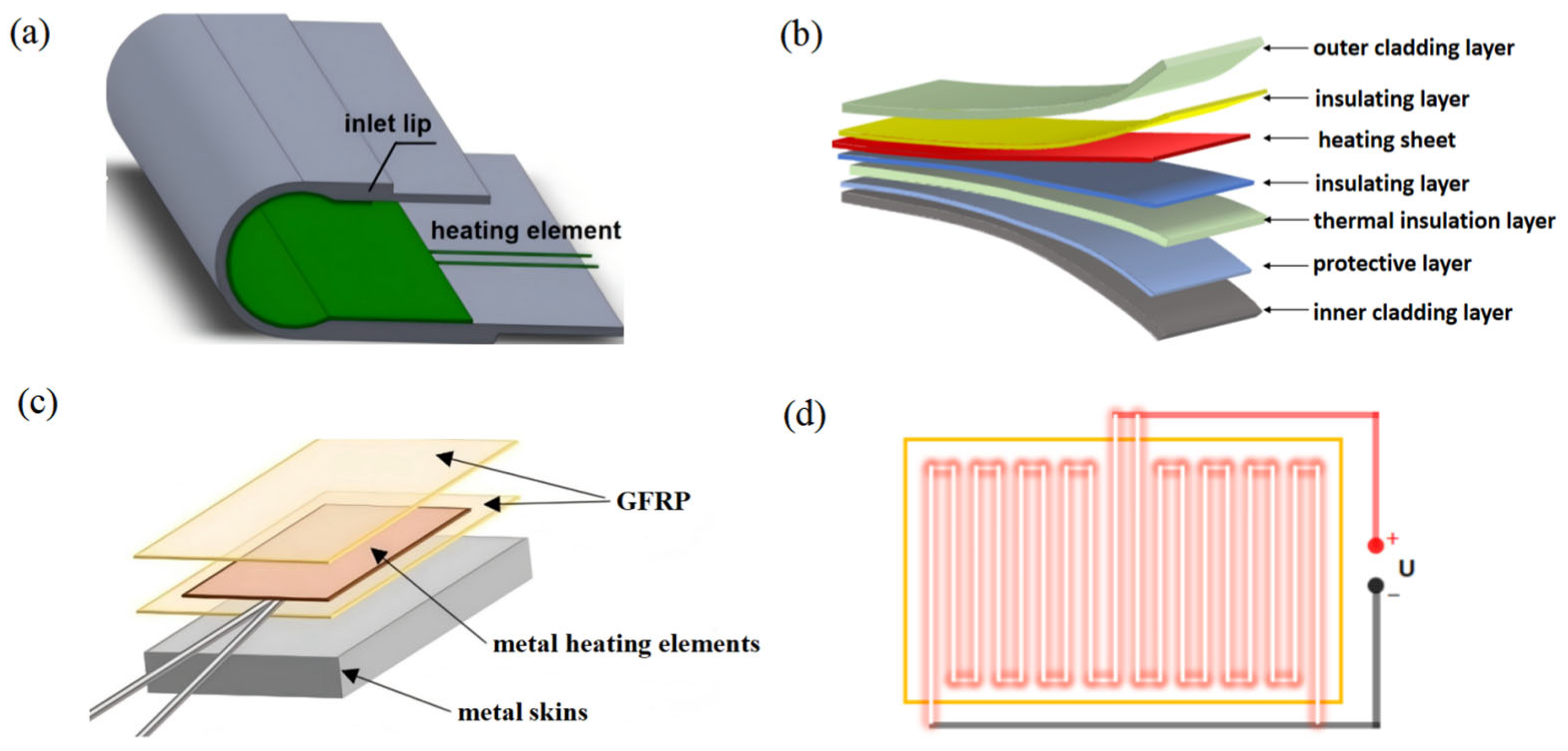
Figure 1. Structure of the integrated electrothermal anti-icing functional components. (a) Conventional adhesive-bonded structure; (b) integrated anti-/de-icing functional structure; (c) heating layer encapsulation process; and (d) schematic diagram of the heating element.
Aerospace 12 00719 g001
Figure 2. Integrated molding process of the anti-icing and de-icing functional structure. The blue arrows indicate the hot-pressing process steps.
Aerospace 12 00719 g002
Figure 3. Interlaminar strength testing by the short-beam method. (a) Dimensions of the heating film; (b) schematic of the hot-press curing process; (c) test equipment configuration; and (d) specimen bending test. In (d), the red rectangular area represents the test sample, and the blue arrows indicate the test steps.
Aerospace 12 00719 g003
Figure 4. Normal-temperature electrothermal performance. (a) Inner surface temperature comparison. (b) Outer surface temperature comparison.
Aerospace 12 00719 g004
Figure 5. Low-temperature dynamic electrothermal performance. (a) Heating curve of low-temperature Sample 1. (b) Heating curve of low-temperature Sample 2.
Aerospace 12 00719 g005
Figure 6. De-icing effect test. (a) Environmental conditions; (b) ice formation diagram of the specimens; (c) close-up diagram of ice formation; (d) de-icing power supply; (e) de-icing effect at 20 s; and (f) surface temperature acquisition. In (b), the red circle shows a partial icing image, and (c) is an enlarged view of the iced part.
Aerospace 12 00719 g006
Figure 7. Heat transfer pathway analysis. (a) Traditional attached heat transfer. (b) Integrated functional–structural heat transfer.
Aerospace 12 00719 g007
Figure 8. Short beam shear test process. (a) Onset of debonding; (b) full debonding; and (c) bending failure.
Aerospace 12 00719 g008
Figure 9. Mechanical properties of specimens with different encapsulation processes. (a) Different electrothermal specimens with varied encapsulation processes. (b) Functionally integrated encapsulation process. The blue arrows in (b) describe the change process of internal interfaces during process forming.
Aerospace 12 00719 g009
Figure 10. Micro-morphology after the electro-thermal coupling experiment. (a) Non-energized intact specimen. (b) Non-energized localized magnification. (c) Post-electrofatigue specimen. (d) Zoomed view of (c). (e) Heating film–metal interface (frontside). (f) Heating film–metal interface (backside). (g) Polished metal substrate. (h) Composite–metal bonding surface.
Aerospace 12 00719 g010aAerospace 12 00719 g010b
Figure 11. Constitutive model of functionally integrated anti-icing/de-icing structure. (a) Constitutive model. (b) Constitutive relation [25,26]. In the (a), the red arrows indicate the thermal stress generated by the heating layer, and the interlaminar stress is divided into three directions: 1, 2, and 3.
Aerospace 12 00719 g011
Figure 12. Heating unit model and initial stress. (a) Heating unit model. (b) Stress nephrogram of heating unit at room temperature.
Aerospace 12 00719 g012
Figure 13. Thermal fatigue and stress contour map of the heating unit. (a) Thermal fatigue cloud diagram after 10,000 cycles. (b) Stress nephrogram after 10,000 cycles. (c) Thermal fatigue cloud diagram after 15,000 cycles. (d) Stress nephrogram after 15,000 cycles. (e) Thermal fatigue cloud diagram after 20,000. (f) Stress nephrogram after 20,000 cycles.
Aerospace 12 00719 g013
Figure 14. Resin damage model after electro-thermal cycling [32]. The black arrows indicate the direction of the externally applied load acting on the material. The numbers (1–4) are used to sequentially mark different characteristic regions of the anti-icing functional layer. The letters A-A’ represent the observation cross-section, and X and Y are for coordinate positioning.
Aerospace 12 00719 g014
Figure 15. Interfacial mechanism in anti-icing structural composites. (a) Operational heating unit specimen. (b) CT scan image of the sample after heating. (c) Interface mechanical damage model [33]. (d) Interaction mechanism at the heating unit interface. In subfigure (a), the square area denotes the thermal stress fatigue region of the anti-icing functional layer, with red arrows indicating the stress coordinates. In subfigure (b), the green scale lines represent the length of internal defects. In subfigure (d), the dashed red circular frame shows the local magnified view of the anti-icing functional layer.
Aerospace 12 00719 g015aAerospace 12 00719 g015b
Table 1. Material parameters of the functionally integrated electrothermal anti-icing structure.
StructureNumber of
Layers
Thickness
(mm)
GradeManufacturer
Outer cladding layer1 layer23A21Guangdong Xingfa Aluminium Co., Ltd. (Foshan, Guangdong Province, China)
Insulating layer2 layers0.5E-7202Tianjin Hanshuo Advanced Materials Co., Ltd. (Tianjin, China)
Heating sheet1 layer0.3HL-368-EJiangsu Huilong Electric Heating Appliance Co., Ltd. (Jiangyin, Jiangsu Province, China)
Thermal insulation layer1 layer0.15E-7202Tianjin Hanshuo Advanced Materials Co., Ltd. (Tianjin, China)
Protective layer1 layer0.75SPC-1Hangzhou Huaju Composite Materials Co., Ltd. (Hangzhou, Zhejiang Province, China)
Inner cladding layer1 layer0.15 E-7202Tianjin Hanshuo Advanced Materials Co., Ltd. (Tianjin, China)
Table 2. Static electro-thermal performance of various anti-/de-icing components.
Test ItemVoltage (V)Current (A)Power (W)Heating Rate
(°C/min)
Electrothermal EfficiencyHeat Flux
Density (W/m2)
Sample 115 V0.66 A9.9 W0.5163.13%515.63
Sample 20.61 A9.2 W0.7667.93%464.65
Table 3. Dynamic electro-thermal performance of various anti-/de-icing components.
Test ItemTemperature
(°C)
Wind Speed
(m/s)
Current (A)Power (W)Heating Rate
(°C/min)
Electrothermal
Efficiency
Heat Flux Density
(W/m2)
Sample 1−15203.37270.13.0067.24%13,743.6
−203.37 A270.32.7666.76%13,842.4
−303.40 A272.22.9666.16%13,967.1
Sample 2−153.37 A270.19.0275.82%13,666.95
−203.37 A270.39.0875.77%13,577.07
−303.40 A272.28.9575.31%13,773.21
Table 4. Comparison of electro-thermal properties of different components.
No.ParameterSample 1 (−30 °C)Sample 2 (−30 °C)Index Improvement Range Remarks
1Heating rate2.96 (°C/min)8.95 (°C/min)+202%(Sample 2 − Sample 1)/(Sample 1)
2Electrothermal efficiency66.16%75.31%+13.8%(Sample 2 − Sample 1)/(Sample 1)
3Minimum surface temperature−6.9 (°C)23.1 (°C)+30.0 (°C)Sample 2 − Sample 1
Table 5. Mechanical properties of different electrothermal specimens.
Experimental SchemeInitial DebondingComplete Debonding
Displacement (mm)Load (N)Shear Strength
τ (MPa)
Error (MPa)Displacement (mm)Load (N)Shear Strength τ (MPa)Error (MPa)
Virgin Specimen0.865122.1730.491.31.636781.9440.372.59
After 10,000 Cycles0.281976.6411.770.590.715734.6934.142.47
After 15,000 Cycles0.372432.8014.481.121.165091.5430.313.94
After 20,000 Cycles0.21785.154.670.830.634249.4825.293.82
Table 6. Mechanical properties of specimens with different encapsulation processes.
Encapsulation MethodInitial Debonding Complete Debonding
Displacement (mm)Load (N)Shear Strength
τ (MPa)
Displacement (mm)Load (N)Shear Strength
τ (MPa)
Sample 10.573329.4123.361.055196.8730.93
Sample 20.865122.1730.491.636781.9440.37
Table 7. Material parameters for each layer in the simulation.
Material NameDensity (kg/m3)Thermal
Conductivity Coefficient (W/(m·K))
Elastic
Modulus (GPa)
Poisson’s RatioCoefficient of Thermal
Expansion (1/°C)
GFRP18000.8300.258 × 10−6
Polyimide14000.22.50.3550 × 10−6
Nichrome alloy (Cr20Ni80)8400152000.316 × 10−6
Disclaimer/Publisher’s Note: The statements, opinions and data contained in all publications are solely those of the individual author(s) and contributor(s) and not of MDPI and/or the editor(s). MDPI and/or the editor(s) disclaim responsibility for any injury to people or property resulting from any ideas, methods, instructions or products referred to in the content.