Article

Numerical Study on Shape Recovery Behaviors of Shape Memory Polymer Composite Hinges Considering Hysteresis Effect

1
LIG Nex1, Yongin-si 16911, Republic of Korea
2
School of Aerospace and Mechanical Engineering, Korea Aerospace University, Goyang-si 10540, Republic of Korea
*
Author to whom correspondence should be addressed.
Aerospace 2025, 12(8), 717; https://doi.org/10.3390/aerospace12080717
Submission received: 18 June 2025 / Revised: 1 August 2025 / Accepted: 3 August 2025 / Published: 12 August 2025
(This article belongs to the Section Astronautics & Space Science)

Abstract

Shape memory polymer composite (SMPC) hinges have been researched as deployable structures in space missions due to their stable and controllable shape recovery behaviors. The elastic energy of the fabrics plays a dominant role in predicting the recovered shape of the hinges, as it strongly drives shape restoration. In this research, the shape recovery behaviors of SMPC hinges are numerically investigated by applying an equation that accounts for the hysteresis characteristics of the fabric reinforcement. The constitutive equation integrates the Mooney–Rivlin model, a viscoelastic, stored energy model, to characterize the hyperelastic properties varying with time, temperature, and shape recovery behaviors of the SMP matrix. Additionally, polynomial functions are introduced to represent the hysteresis effects and energy dissipation behavior of the fabrics. Since the elasticity of fabrics significantly affects the shape recovery of SMPCs, the developed constitutive equation enables accurate prediction of the recovered configuration. Finite element method analysis is performed based on this model and validated through comparison with experimental results. Finally, the constitutive equation is applied to investigate the shape memory response of SMPC hinges. The simulations present the significant design factors to increase the shape recovery ratio of the SMPC hinges.

1. Introduction

Deployable structures in space missions heavily rely on hinge mechanisms, which traditionally suffer from mechanical wear, lubricant evaporation in vacuum, and reduced functionality under extreme thermal cycling. These issues pose significant risks to mission longevity and reliability. Recent studies in shape memory polymer composite (SMPC) hinges offer a promising alternative [1,2,3]. SMPCs can be solid-state actuation without moving parts or lubricants, thereby eliminating traditional failure reasons. Their lightweight nature and high adaptability to space environments allow for simplified design, lower mass, and enhanced thermal stability. Furthermore, SMPC hinges exhibit excellent shape recovery and can be programmed for controlled deployment [4,5]. This technology represents a transformative approach to overcoming limitations of conventional hinge systems, with ongoing research focusing on improving recovery stress, deployment repeatability, and long-term performance in orbit.
Since SMPCs have temperature-dependent shape recovery characteristics, heating methods play a crucial role. Conventionally, heating SMPCs are achieved by putting functional particles into SMPs [6,7,8,9] or attaching a resistive Joule heating element to SMPCs [10,11,12]. However, those methods have limitations such as uneven temperature distribution, and reduction in recoverable deformation depends on particle content. Furthermore, the attachment of heating elements significantly reduces the deformable strain of the material. To overcome these limitations, SMPCs reinforced with conductive fabrics have been introduced as a viable solution. Several studies have demonstrated that such composites provide a more uniform temperature distribution while maintaining the inherent deformability of the structure [13,14,15]. Moreover, these composites exhibit tunable stiffness and shape recovery behavior, depending on both the temperature and the orientation of the reinforcing fibers.
For the practical application of SMPCs in deployable structures, it is crucial to accurately predict their thermomechanical responses, including their time- and temperature-dependent deformation and shape recovery characteristics. Some prior research has explored the advanced thermomechanical modeling of SMPCs, incorporating the hyper-viscoelastic nature of SMPs as well as the anisotropic behavior of the fabric reinforcements [16,17,18]. In particular, anisotropic, hyper-viscoelastic models have been used to evaluate the shape recovery of deployable SMPC antennas by accounting for thermal residual stresses [19]. In such systems, the shape recovery is driven by a combination of elastic energy from the fabrics and recovery energy stored in the SMPs [20,21]. Given that the elastic energy contribution from the fabrics generally exceeds that of the SMPs, it becomes essential to formulate an accurate constitutive model capable of capturing the anisotropic mechanical response of the fabric components.
Traditionally, elasto-plastic modeling approaches have been applied to characterize the plastic deformation [22,23], hysteresis [24], and cyclic loading behaviors [25,26] observed in SMPC systems. However, these models often require complex implementation within finite element frameworks and involve challenges in parameter identification. As a simplified alternative, the total strain formulation has been adopted, as it facilitates direct manipulation of the energy expressions. One such model based on continuum mechanics employs the total strain approach to describe the hyperelastic response of fiber-reinforced systems [27]. Many of the existing models in this category incorporate hyperelastic fiber formulations that reflect the influence of fiber orientation under large deformations [18,28,29,30,31]. Several models that incorporate the interaction mechanisms between the polymer matrix and fabrics have been shown to yield improved predictive accuracy [32,33]. Experimental investigations have further revealed that fabric reinforcements exhibit both energy dissipation and hysteretic characteristics [34,35], and that incorporating residual deformations can enhance the reliability of hysteresis predictions [36,37,38].
In this study, a numerical analysis is developed to investigate the shape recovery behavior of SMPC hinges by employing a constitutive model designed to represent the dissipative energy characteristics of fabric reinforcements. Due to the hysteretic nature of the shape recovery process, the proposed model enables more precise predictions of the final recovered shapes compared to conventional numerical approaches. The time- and temperature-dependent behaviors of SMPs are modeled using a combination of the Mooney–Rivlin framework, viscoelastic theory, and stored strain energy concepts. Additionally, polynomial expressions are utilized to represent the viscoelastic and hysteresis behaviors of the fabrics. The model parameters for SMPs are derived from tensile testing, dynamic mechanical analysis (DMA), and shape recovery experiments. For the fabric materials, parameters are obtained through tensile testing, stress relaxation, and hysteresis evaluation. The numerical analysis based on the finite element method is conducted, and its accuracy is evaluated through comparison with experimental results obtained from mechanical testing of SMPCs, such as uniaxial tensile, bias-extension, stress relaxation, and shape recovery tests. Finally, the shape recovery simulation of SMPC hinges under bending load are conducted using the constitutive equations. Assuming SMPC hinges are used in a solar panel array, the study numerically investigates the influence of bending load, cooling time, stowing time, and reheating time on the shape recovery behaviors.

2. Constitutive Equations

In this section, constitutive equations for shape recovery behaviors of SMPCs considering hysteresis effect are derived based on Helmholtz free energy. The constitutive equation for hyper-viscoelastic and shape memory characteristic of SMPs is explained in Section 2.1 and Section 2.2. The hyperelastic model for fabrics including hysteresis effect is expressed in Section 2.3.
In accordance with the Clausius–Planck inequality derived from the first and second laws of thermodynamics, a constitutive formulation can be established using the Helmholtz free energy function [39]. The representation of the Helmholtz free energy for composite materials is given by Equation (1):
Ψ c o m p o s i t e = Ψ m a t r i x C , Γ 1 m , , Γ i m + Ψ f a b r i c C , Γ 1 f , , Γ j f , a 0 , b 0
where Ψ m a t r i x and Ψ f a b r i c denote the free energy contributions from the shape memory polymer matrix and the anisotropic fabric reinforcements, respectively. C represents the right Cauchy–Green strain tensor; Γ i m and Γ j f are internal variables describing the relaxation behavior of the matrix and fabric components. a0 and b0 correspond to the unit directions of weft and warp fibers in the reference configuration.

2.1. Constitutive Equation for the SMPs

The Helmholtz free energy function for the SMP matrix is expressed in Equation (2):
Ψ S M P s = Ψ v o l J + Ψ i s o C ¯ + i = 1 k γ i m C ¯ , Γ i m
where C ¯ = J 2 / 3 C , is the volume-preserving part of the right Cauchy–Green deformation tensor, and J is the determinant of the deformation gradient (volume ratio). Ψ i s o and Ψ v o l denote the volumetric and isochoric energy terms, respectively. The superscript m indicates association with the matrix, and Υ i m captures the viscoelastic dissipation potential. Assuming the material is nearly incompressible (J = 1), the isochoric part can be described using the Mooney–Rivlin formulation [40], as shown in Equation (3):
Ψ i s o = C 10 I 1 3 + C 01 I 2 3 ,   Ψ v o l = 0
where C10 and C01 are material constants; I1 and I2 represent the first and second strain invariants.
The mechanical response of SMPs under deformation is modeled using a one-dimensional rheological representation (Figure 1), where spring and dashpot components represent equilibrium and non-equilibrium responses. Maxwell elements, consisting of a spring and dashpot in series, characterize the time-dependent viscoelastic behavior. The stored strain, ε s , accounts for energy accumulation in the material. Based on the non-equilibrium stress formulation derived from this rheological model, the second Piola–Kirchhoff stress and corresponding elasticity tensors are given by the following relations:
S S M P s = 2 1 + i = 1 k β i m e x p ξ i m C 10 I + C 01 I 1 I C ¯ + i = 1 k H i , n m
H i , n m = e x p ξ i m Q i , n 1 m e x p ξ i m β i m S i s o , n 1 m ,   ξ i m = 0.5 t τ i m
Q i , n 1 m = β i m e x p ξ i m S i s o , n 1 m + e x p ξ i m Q i , n 2 m e x p ξ i m β i m S i s o , n 2 m ,   i = 1 , ,   k
C S M P s = 4 C 01 1 + i = 1 k β i m e x p ξ i m I I I I
Here, the superscript m denotes that the quantities correspond to the matrix (SMPs), Δt refers to the increment of time, while β i m and ξ i m are the dimensionless variables associated with viscoelastic behavior, respectively; τ i m denotes the retardation time, Q i , n 1 m represents the previous time-step stress, while H i , n m is the history-dependent stress component.
Based on the assumption that the SMPs are nearly incompressible materials, for the uniaxial tensile test, Equations (4) and (7) can be expressed as Equations (8) and (9).
S u = 2 λ u 2 1 λ u C 10 + C 01 2 λ u
E = 1 + i = 1 k β i m e x p ( ζ i m ) 1 E u n r l e x  
where λ u and E indicate the stretch ratio and elastic modulus in the loading direction, w is the frequency, and Eunrlex is the elastic modulus prior to stress relaxation. Equation (9) can be expressed in the frequency domain as follows [41]:
E = 1 i = 1 k β i m 1 w 2 τ i m 2 + 1 E u n r l e x  
Due to the matrix exhibiting time- and temperature-dependent behavior, the time–temperature superposition principle (TTSP) is utilized to identify the dimensionless parameters related to viscoelasticity based on their values at the glass transition temperature, Tg, as shown in Equation (11).
ζ i m T = ζ i , T g m α T T
where T is the current temperature, ζ i , T g m is the dimensionless parameter at Tg. The shift factor, αT, which varies the temperature, is often expressed using the Williams–Landel–Ferry (WLF) equation [42].
log α T = C 1 T T g C 2 + T T g
where C1 and C2 are coefficients derived through interpolation of experimental shift factor data.

2.2. Constitutive Equation for Shape Memory Behaviors

SMPs possess the unique ability to retain a temporary shape and return to their original form when exposed to appropriate thermal conditions. When these materials mechanically deformed at temperatures above Tg, and subsequently cooled below Tg, the deformation is preserved in the form of internal strain energy. Even after the removal of the applied load, the deformed shape remains stable. Upon reheating the polymer above Tg, the stored energy is released, and the original shape is restored. To mechanically represent this phenomenon, the frozen fraction model is frequently utilized [43]. This model conceptualizes the polymer as comprising a blend of active and frozen molecular segments, where the frozen segments are responsible for energy storage. The proportion of the frozen phase is described using a logistic-type function as shown in Equation (13).
ϕ f T = 1 1 + T 0 T h s = ε * ε p r e
In this equation, ϕ f represents the frozen fraction; T0, h, and S are empirically determined parameters, ε p r e is the pre-deformed strain, and ε * is the recovered strain. Assuming that the stresses in the frozen and active phases are identical, the total strain can be expressed as the sum of the mechanical, thermal, and stored strains, as presented in Equation (14).
E = E M + E T + E S
where E, EM, ET, and ES are the total, mechanical, thermal, and stored strains, respectively. Those strains can be defined as Equations (15) to (17).
E M = ϕ f C l 1 + 1 ϕ f C h 1 : S
E T = T 0 T ϕ f α f + 1 ϕ a α a d T I
d E S d T = C h 1 : ϕ f C l 1 + 1 ϕ f C h 1 1 : E E S E T d ϕ f d T
In the above, C l and C h represent the elastic stiffness tensors at low and high temperatures, respectively, while αf and αa denote the thermal expansion coefficients for the frozen and active phases.

2.3. Constitutive Equation for the Fabric

The constitutive behavior of fabrics under mechanical loads can be described using the Helmholtz free energy models expressed as Equation (18).
Ψ f a b r i c = Ψ t e n s i l e C , a 0 , b 0 + Ψ s h e a r C , a 0 , b 0 + j = 1 p γ j f C ¯ , Γ j f , C , a 0 , b 0
Here, Ψ t e n s i l e and Ψ s h e a r account for the fabrics’ response under uniaxial tension and shear, respectively. The third term Υ j f represents energy dissipation associated with viscoelastic effects. The unit vectors a0 and b0 define the orientations of the weft and warp fibers in the unreformed configuration. Assuming that the external load is applied in the y-direction (Figure 2), these vectors are given as Equation (19).
a 0 = cos θ a sin θ a 0 ,   b 0 = cos θ b sin θ b 0
where θ a and θ b are the initial angle of the weft and warp fibers, respectively. The anisotropic response of the fabrics is captured using polynomial functions of pseudo-invariants Equations (20) and (21).
Ψ t e n s i l e = k 1 I 4 1 4 + k 2 I 4 1 3 + k 3 I 4 1 2     for   weft   k 4 I 6 1 4 + k 5 I 6 1 3 + k 6 I 6 1 2     for   warp
Ψ s h e a r = k 7 I 10 4 + k 8 I 10 3 + k 9 I 10 2
Here, I4, I6, and I10 are pseudo-invariants representing fiber stretch in the weft, warp directions, and the change in the angle between fibers, respectively. The coefficients ki (i = 1,⋯, 9) are obtained through curve-fitting to experimental data. To model the residual deformation due to hysteresis during unloading, the proposed invariants model is shown as Equation (22).
I 4 C , a 0 = a 0 · C a 0 δ r e , 4 ,   I 6 C , b 0 = b 0 C · b 0 δ r e , 6
The residual deformations in the weft and warp direction ( δ r e , 4 and δ r e , 6 ) are defined based on loading unloading states as presented in Equation (23).
δ r e , 4 = 0                         for   loading ε r e , 4 + 1 2 1     for   unloading   δ r e , 6 = 0                         for   loading ε r e , 6 + 1 2 1     for   unloading
Here, ε r e , 4 and ε r e , 6 denote the residual strains in the weft and warp directions, respectively.
The mechanical response of the fabrics is also modeled using a one-dimensional rheological system similar to that of SMPs as presented in Figure 2. ε r e represents the remaining strain resulting from the hysteresis response of fabrics. From the definition of the non-equilibrium stress, the three-dimensional stress tensor and corresponding moduli can be given as Equations (24) to (28).
S f a b r i c = 2 1 + j = 1 p β j f e x p ξ j f 4 k 1 I 4 1 3 + 3 k 2 I 4 1 2 + 2 k 3 I 4 1 A 0 + 4 k 4 I 6 1 3 + 3 k 5 I 6 1 2 + 2 k 6 I 6 1 B 0 + 2 4 k 7 I 10 3 + 3 k 8 I 10 2 + 2 k 9 I 10 G 0 + j = 1 p H j , n f
H j , n f = e x p ξ j f Q j , n 1 f e x p ξ j f β j f S t e n s i l e , n 1 ,   ξ j f = 0.5 t τ j f  
Q j , n 1 f = β j f e x p ξ j f S t e n s i l e , n 1 + e x p ξ j f Q j , n 2 f e x p ξ j f β j f S t e n s i l e , n 2 ,   j = 1 , ,   p
G 0 = 1 2 I 10 + a 0 · b 0 1 I 4 A 0 + 1 I 6 B 0 + I 4 I 6 1 2 a 0 · b 0 + I a 0 · C b 0 I 4 I 6 1 2 a 0 · b 0
C f a b r i c = 8 1 + j = 1 p β j f e x p ξ j f 6 k 1 I 4 1 2 + 2 k 2 I 4 1 + k 3 A 0 A 0 + 6 k 4 I 6 1 2 + 3 k 5 I 6 1 + k 6 B 0 B 0 + 8 6 k 7 I 10 2 + 3 k 8 I 10 + k 9 G 0 G 0
where A0 and B0 are the cross-product of the unit vectors.
Assuming that the fabric is nearly incompressible, the pseudo-invariants can be transformed into a function of the stretch ratio such as I 4 = λ w e f t 2 , I 6 = λ w a r p 2 , and I 10 = Δ φ . The tensile and shear stresses can be rewritten as described in Equations (29) and (30).
S t e n s i l e = 2 4 k 1 λ w e f t 2 1 3 + 3 k 2 λ w e f t 2 1 2 + 2 k 3 λ w e f t 2 1 f o r   w e f t 2 4 k 4 λ w a r p 2 1 3 + 3 k 5 λ w a r p 2 1 2 + 2 k 6 λ w a r p 2 1   f o r   w a r p
S s h e a r = 2 4 k 7 Δ φ 3 + 3 k 8 Δ φ 2 + 2 k 9 Δ φ

3. Validation of the Constitutive Equations

In this section, the constitutive equtaions are verified by comparing with the experimental results of SMPCs. To obtain the coefficients of the constitutive equations in Section 3.1, the tests for SMPs and fabrics are conducted. Section 3.2 shows the comparison between simulation and experimental results for tensile and shape memory tests of SMPCs. The descriptions of the test method to validate models and related coefficients are summarized in Table 1 and Table 2.

3.1. Coefficients Acquisition Test

3.1.1. Model Coefficients Associated with SMPs

The model coefficients for hyperelasticity, viscoelasticity, stored strain energy, and thermal expansion are identified through uniaxial tension, DMA, shape recovery tests, and thermal strain data for SMPs. To prepare test specimens, except for DMA test, a thermoset polyurethane SMP (Diaplex Inc. MP4510) is placed into a dog-bone-shaped mold. Then it is cured at 75 °C for 2 h to obtain a thickness of 2 mm. The test is performed using a thermal chamber and materials testing system (MTS, MTS810), while specimen temperatures are monitored using a thermocouple (Figure 3). The dimensions of DMA test specimen are 20 mm (l) × 10 mm (w) × 2 mm (t).
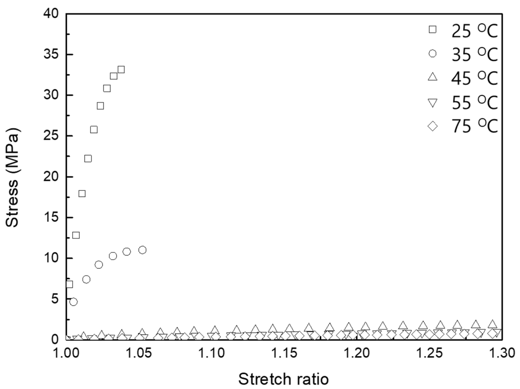
The uniaxial tensile test is conducted in accordance with the standard method for evaluating the tensile properties of plastics [44]. During the test, the crosshead speed is maintained at 10 mm/min, and the temperature varies from 25 °C to 75 °C. As shown in Figure 4, the elastic modulus gradually declines when the specimen temperature exceeds 45 °C. Specimens tested at 25 °C and 35 °C exhibit failure at a stretch ratio near 1.05, because the SMP shows brittle behavior in this temperature range, where phase transition is minimal. The hyperealstic model coefficients are determined by interpolating the tensile data using Equation (4) as shown in Table 3.
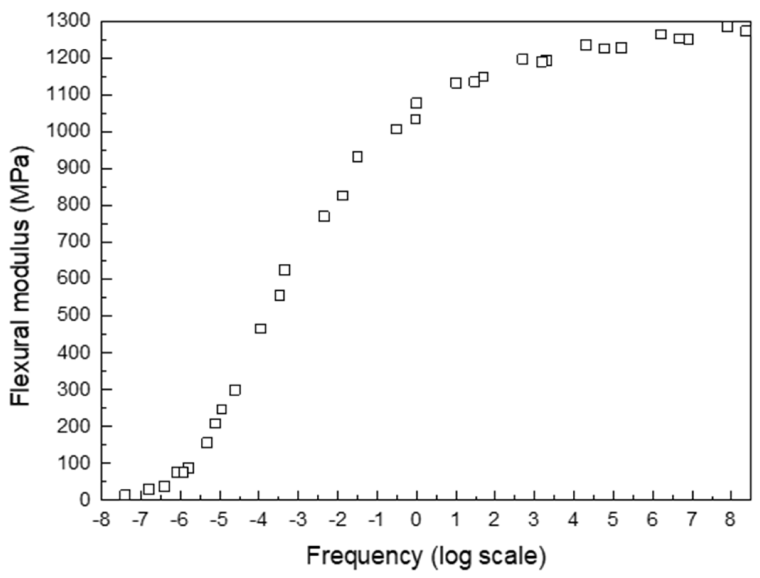
The DMA test is performed using a DMA Q800 (TA Instrument) in accordance with the standard practice for the dynamic mechanical properties of plastics [45]. Using the fixed frequency with stress amplitude approach, the specimen is clamped at both ends, and the flexural modulus is measured over a temperature range of 25–75 °C at 5 °C intervals. The heating rate is set to 5 °C/min, and the test is conducted at three frequencies: 1 Hz, 10 Hz, and 30 Hz. The corresponding flexural moduli at different temperatures and frequencies are shown in Figure 5. Although the test results show that the flexural modulus transition appears around 55 °C, which is slightly different from Tg, this discrepany does not significantly affect the evaluation of the relaxation chracteristics. To construct the master curve covering the full frequency spectrum, the flexural modulus values at different temperatures are horizontally shifted to align with the reference temperature of Tg. The logarithmic shift factors applied in this study are presented in Figure 6, and the resulting time–temperature-shifted modulus data are illustrated in Figure 7. The shifted modulus data clearly demonstrates that the flextural modulus varies form 1.3 GPa to 10 MPa depending on the temperature and testing freqeucny. To derive the coefficients of the five-term viscoelastic model in the time domain from DMA data in the frequency domain, the model is transformed into the frequency domain [41]. These coefficients are extracted by fitting the master curve using the frequency domain expression for the elastic modulus. Additionally, the coefficients for the WFL equation are obtained by fitting the shif factor curve using Equation (12). A summary of the resulting coefficients for SMPs is provided in Table 4 and Table 5.
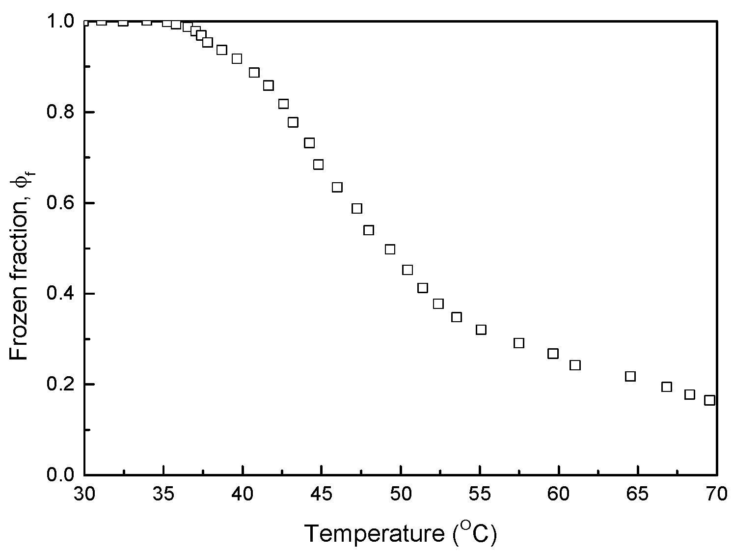
The shape recovery test evaluates the frozen fraction as the temperature of SMPs increases. The frozen fraction is calculated by dividing the amount of strain recovered by the initially applied deformation. To ensure consistent thermal conditions for accurate numerical comparison with SMPCs, the SMPs are heated for a duration of 10 s. The measured frozen fractions at various temperatures (up to 70 °C) are illustrated in Figure 8. This figure indicates that little phase transition occurs below 35 °C, while continuous phase transition is observed as the temperature increases beyond this temperature. These findings provide a basis for explaining the brittle behavior of the SMP and SMPC at temperatures below 35 °C. The corresponding coefficients are derived by fitting the data using Equation (13), resulting in T0 = 40.41 °C, s = 0.154, and h = –22.63.
Due to isotropic behavior of the SMPs, thermal strain is measured one-dimensionally as the specimen temperature increases from 25 °C to 75 °C. The thermal strain is represented as a second-order polynomial function of temperatures, that is, ε T = a T 2 + b T + c , where temperature is expressed in Kelvin. The coefficients are determined by interpolating the experimental thermal strain as a = 7.75 × 10⁻⁷, b = −4.38 × 10⁻⁴, and c = 0.061.

3.1.2. Model Coefficients Associated with Fabrics

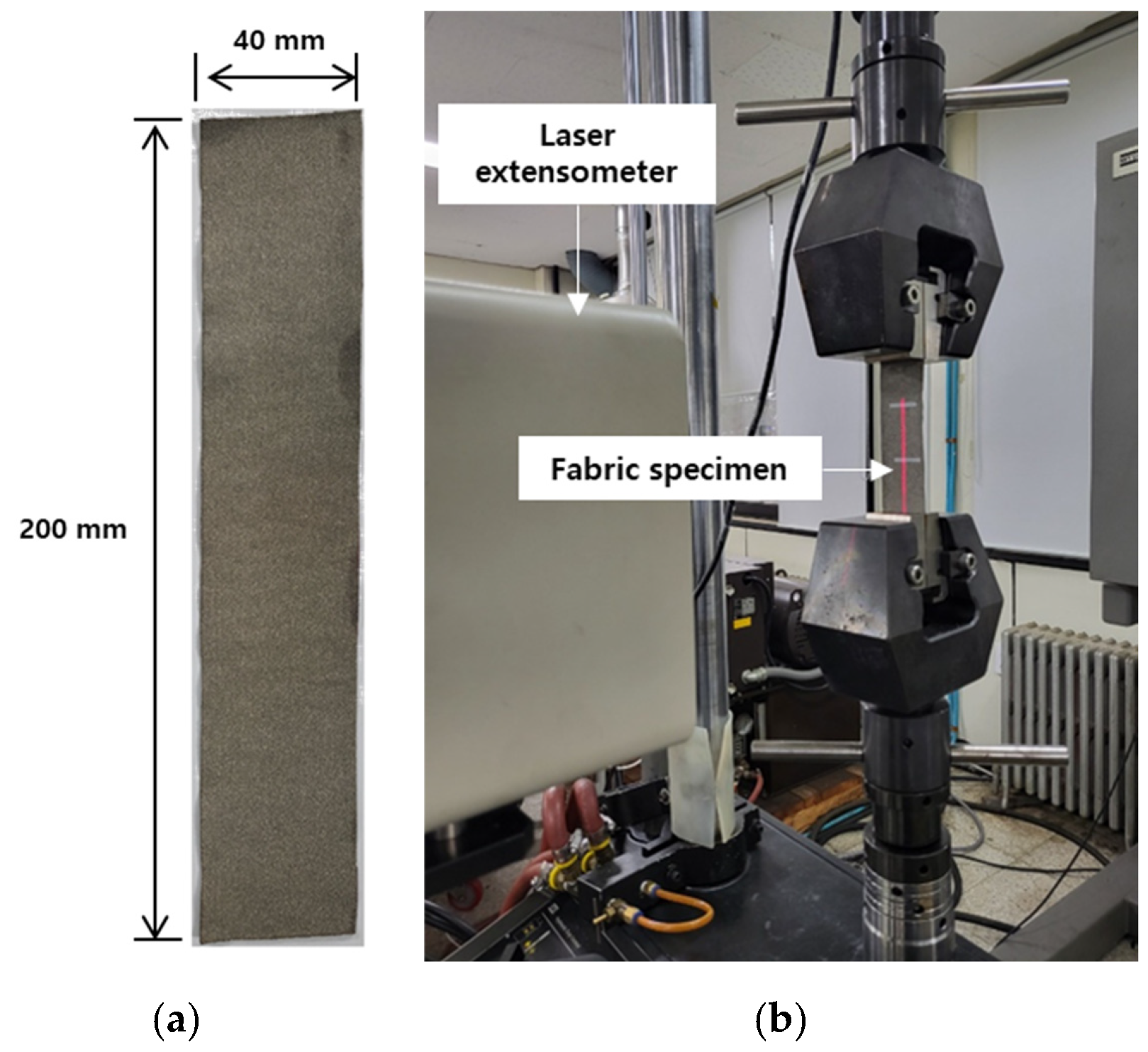
To identify the anisotropic and viscoelastic model coefficients, as well as the residual strains, uniaxial tensile, bias-extension, stress relaxation, and hysteresis tests are conducted on fabric specimens (Figure 9). The tested fabric (Soitex, HTL-1) is coated with silver powder and consists of nylon fibers in the warp direction and spandex fibers in the weft. The specimen is prepared in a rectangular geometry. Although nylon has temperature-dependent properties, it is experimentally observed that the mechanical properties of fabric in the warp direction are not significantly affected by temperature within the range of temperature encountered in this research (Figure 10). So, the tests for the fabric are conducted at room temperature. Strain measurements are obtained using a laser extensometer, while the angle between the weft and warp fibers is monitored through photogrammetry. The fabric specimen has a thickness of 0.31 mm. A crosshead speed of 10 mm/min is applied during both the loading and unloading phases.
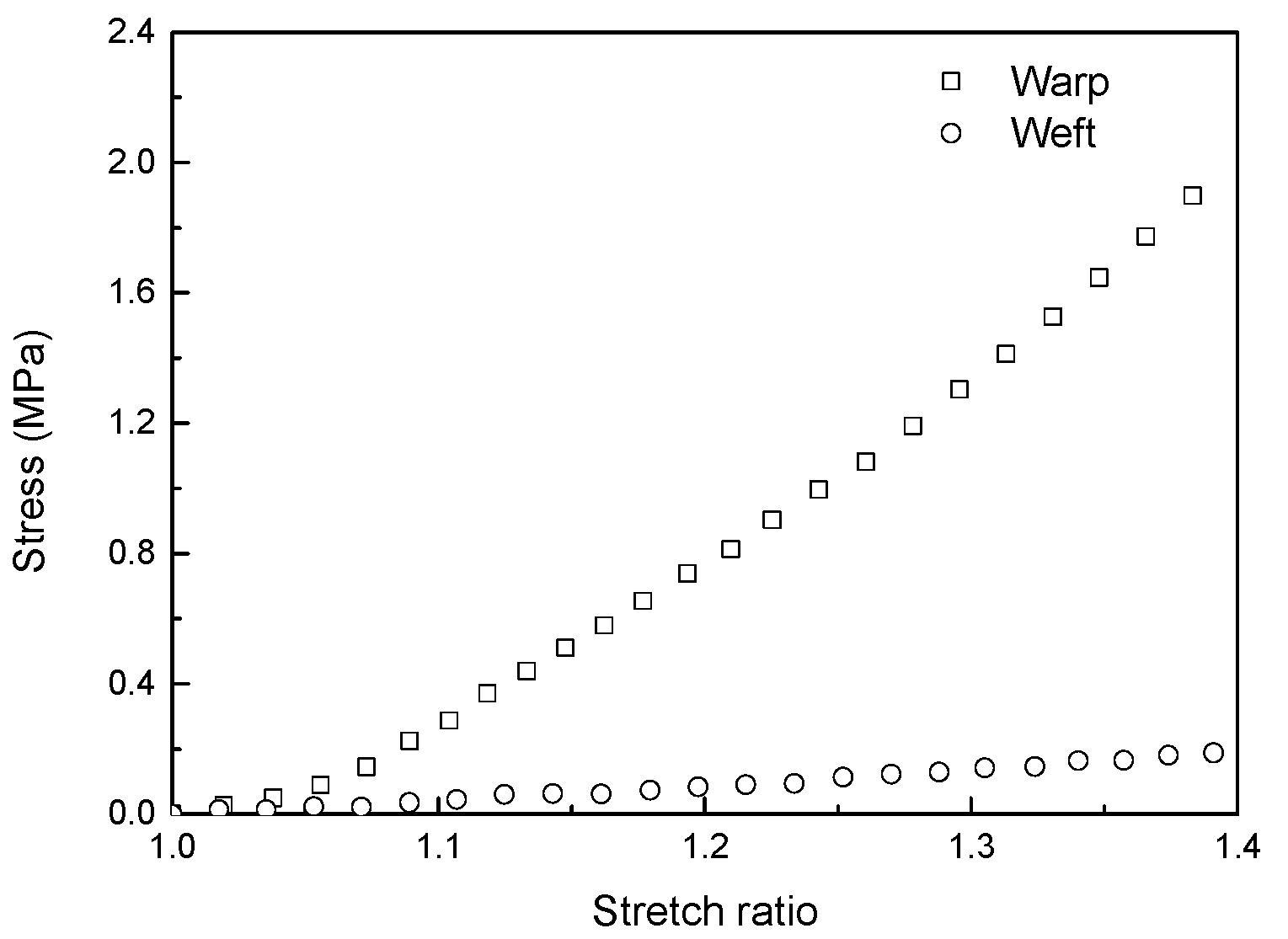
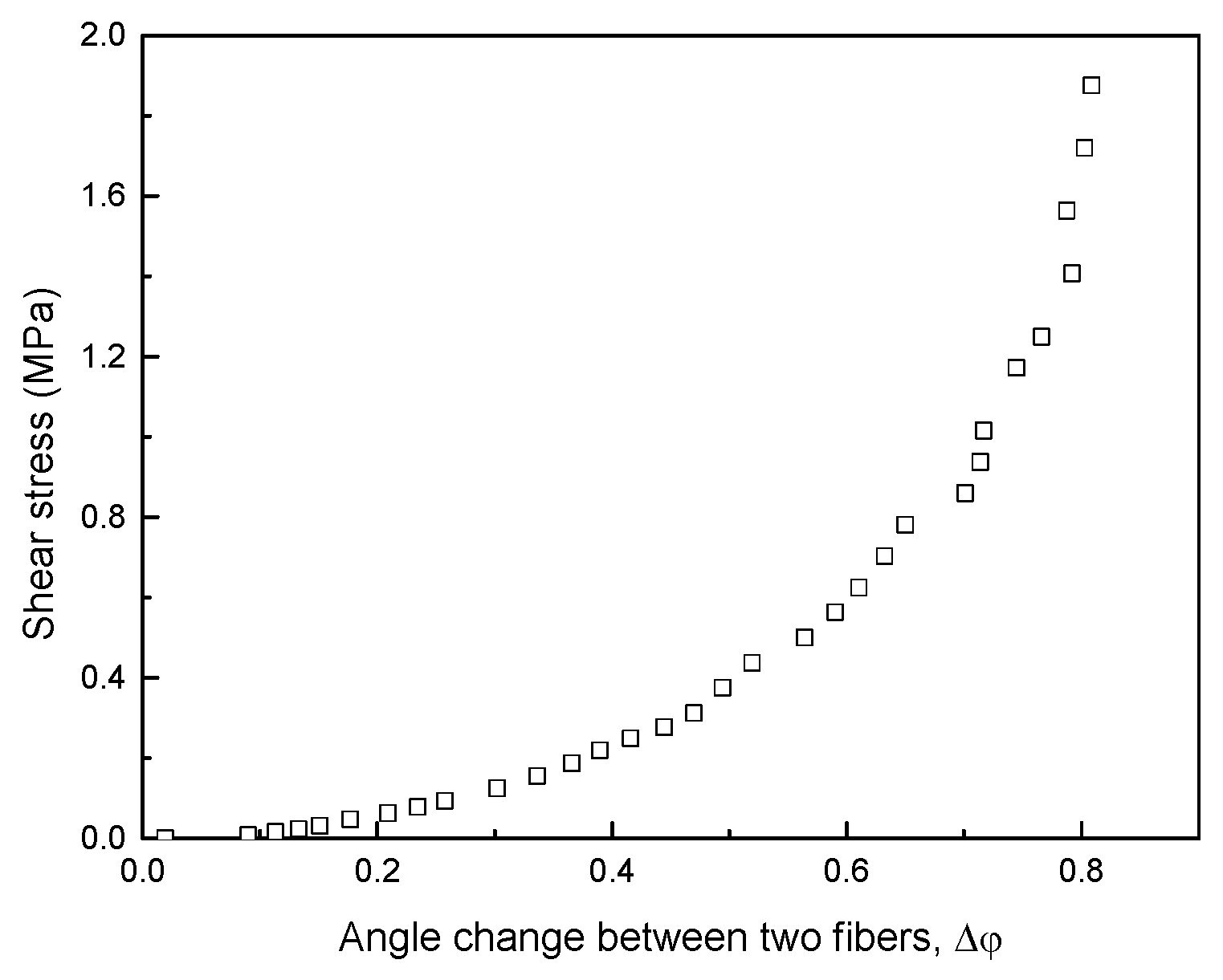
In the uniaxial tensile and bias-extension tests, specimens are stretched along orientations initially aligned at 0/90° and ±45° with respect to the loading direction, respectively. The bias-extension test is specifically used to evaluate the shear behavior of woven fabrics. The corresponding results are shown in Figure 11 and Figure 12. Since the fabric consists of nylon fibers in the warp direction and spandex fibers in the weft direction, the stiffness and strength in the warp direction are much higher than those in the weft direction. Although the specimen can be stretched beyond a stretch ratio of 1.4 in both directions. In both tests, the tensile and shear stresses exhibit a sharp increase as the specimen is stretched. The coefficients associated with uniaxial and shear properties are extracted by interpolating the experimental data using Equations (29) and (30). The resulting parameters for the fabric materials are listed in Table 6 and Table 7.
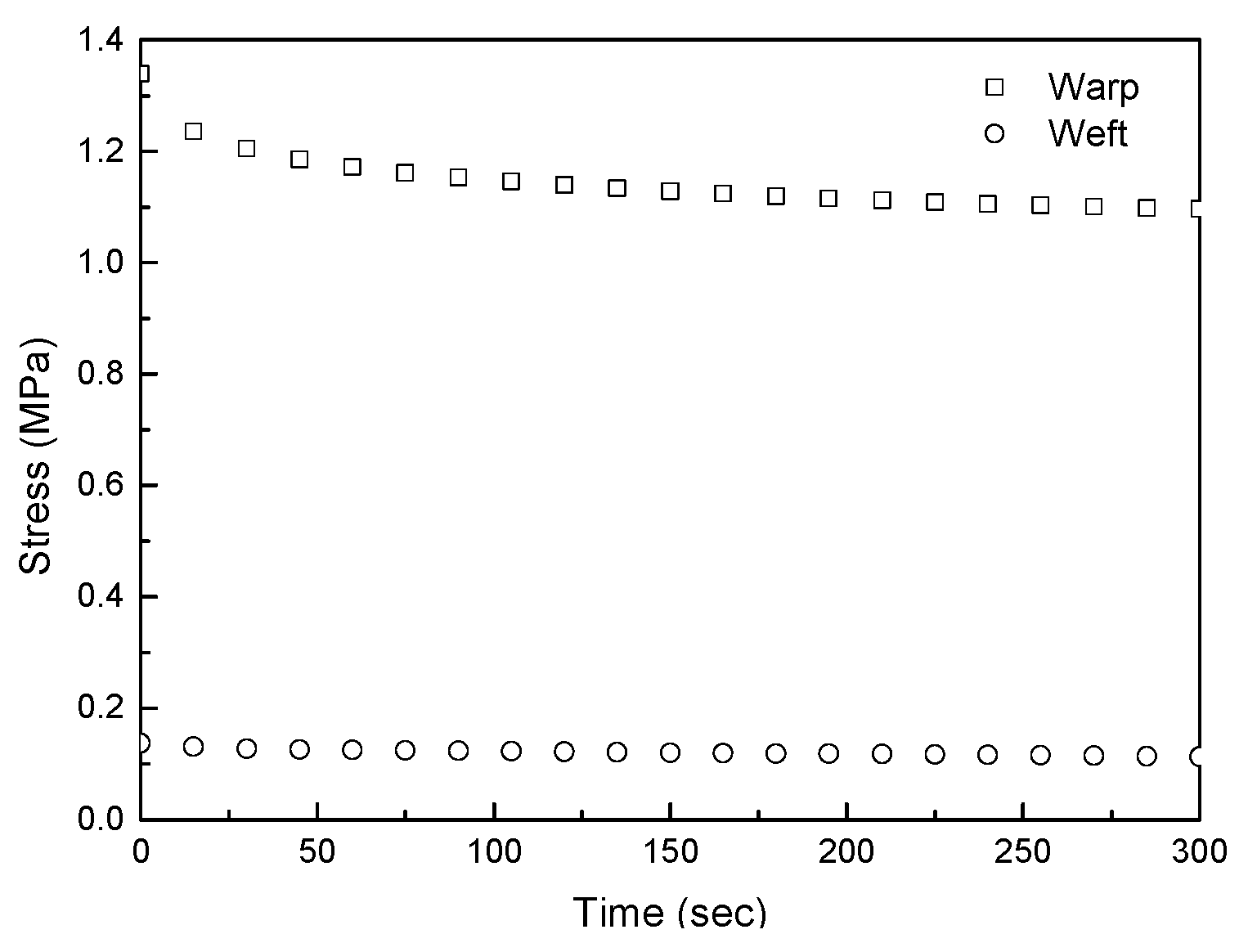
The stress relaxation behavior of the fabrics is evaluated after the fabric is stretched to a ratio of 1.3, and the decreased stress is obtained over a period of 300 s while maintaining the constant stretch ratio (Figure 13). The stress in both weft and warp directions decrease by 0.023 MPa and 0.243 MPa, respectively. After 300 s, the stress variation is approximately 1%. The hyperelastic model coefficients are derived by interpolating the experimental relaxation data using a three-term viscoelastic model for fabrics, as presented in Table 8.
The hysteresis behavior, which reflects the stress–strain response during both loading and unloading cycles, is presented in Figure 14. The fabric specimens are stretched to a strain corresponding to a stretch ratio of 1.3 and subsequently unloaded until the stress returned to zero. The area ratio between the loading and unloading curves represents the ratio of dissipated energy. The energy dissipation ratio is measured as 0.35 in the weft direction and 0.59 in the warp directions. Additionally, the residual strains recorded in these directions are 0.057 and 0.039, respectively. The equation employed to interpolate the uniaxial test data is utilized to derive the coefficients of the hyperelastic model under loading conditions. The resulting coefficients for the fabrics are summarized in Table 9.

3.2. Thermomechanical Characteristics of SMPCs

3.2.1. Fabrication and Experimental Setup for SMPCs

The SMPC specimen is produced using a single ply of fabric (Soitex, HTL-1) and the SMPs (Diaplex Inc. MP4510). The fabrication process consists of the following steps:
(1)
Place the fabric onto a flat mold surface.
(2)
Attach copper sheets to both fabric ends using an adhesive film (Loctite 9695) for consistent electrical conductivity across the SMPCs.
(3)
Cure the adhesive at 85 °C for 30 min followed by 125 °C for 2 h.
(4)
Pour the SMPs onto the fabric and layer it with a release film, caul plate, and breather.
(5)
Seal the assembly using vacuum film and sealant tape.
(6)
Cure the assembly at 80 °C for 2 h, followed by curing at 125 °C for 2 h.
The thickness of the fabricated specimen is approximately 0.32 mm, and its configuration is illustrated in Figure 15. The fiber volume fraction is measured to be 0.499 based on the density of the fabric and the SMPs. Due to the silver powder coating on the fabric, the specimen is capable of resistive heating. Temperature measurements using a thermocouple and thermal camera confirm that the specimen surface heats uniformly, reaching temperatures above 95 °C (Figure 16).
The results from the experiments are compared with those derived from numerical analysis. The analysis employs a total Lagrangian formulation with nonlinear geometry considerations, utilizing 8-node solid elements characterized by three translation degrees of freedom. The geometry of the analysis model is the same as actual dimensions of the SMPC specimen. The mesh consists of 40, 8, and 1 elements along the length, width, and thickness direction, respectively. Boundary conditions and loading scenarios are set identically to those used in the experiments. Due to the complexity of the model, convergence verification of the internal calculations is essential. Therefore, the analysis is carried out using a custom-developed MATLAB code (R2022b). In this analysis, SMPCs are assumed to be anisotropic materials, with their stress and elasticity tensors incorporated based on the equivalent model given in Equation (1).

3.2.2. Anisotropic Hyper-Viscoelastic Response

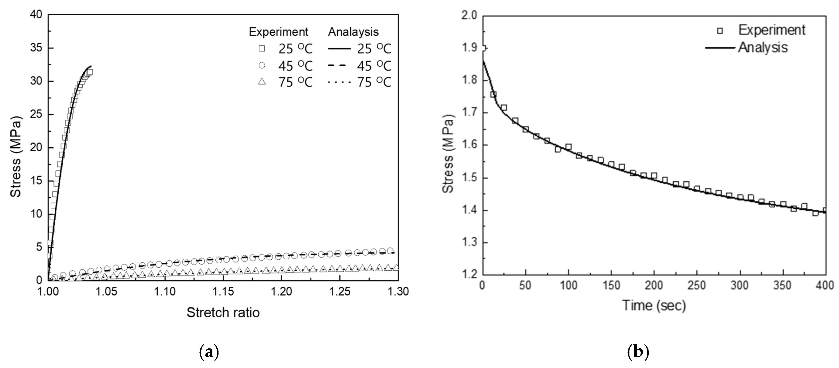
Time- and temperature-dependent mechanical responses are evaluated through uniaxial tensile and stress relaxation experiments. The tensile tests are conducted following the standard test method for the tensile properties of polymer matrix composite materials [46]. The tests are carried out at temperatures ranging from 25 °C to 75 °C, with a constant loading rate of 10 mm/min. To investigate the time-dependent behavior, the specimen is stretched to a stretch ratio of 1.3 at the same rate and then held in the deformed state for 7 min while monitoring the stress relaxation. Since viscoelastic effects are primarily exhibited above Tg, the relaxation tests are performed at 75 °C. Figure 17 presents the comparison between the measured data and the numerical analysis. Compared with the tensile response of SMPs, the SMPCs exhibit a higher modulus, which is 1.74 GPa. As the mechanical properties of the SMP degrade rapidly near Tg, the SMPC exhibits a drastic reduction in tensile modulus, decreasing from 1.74 GPa at 25 °C to 14.6 MPa at 75 °C. The SMPCs can undergo deformations exceeding 1.3 times their original length above Tg. During the stress relaxation phase, the stress decreases by approximately 13% within 1 min and by about 26% within a 7 min period. The consistency between the experimental tests and the analysis confirms that the proposed constitutive model reliably predicts the thermo-viscoelastic behavior of SMPCs.

3.2.3. Shape Memory Response

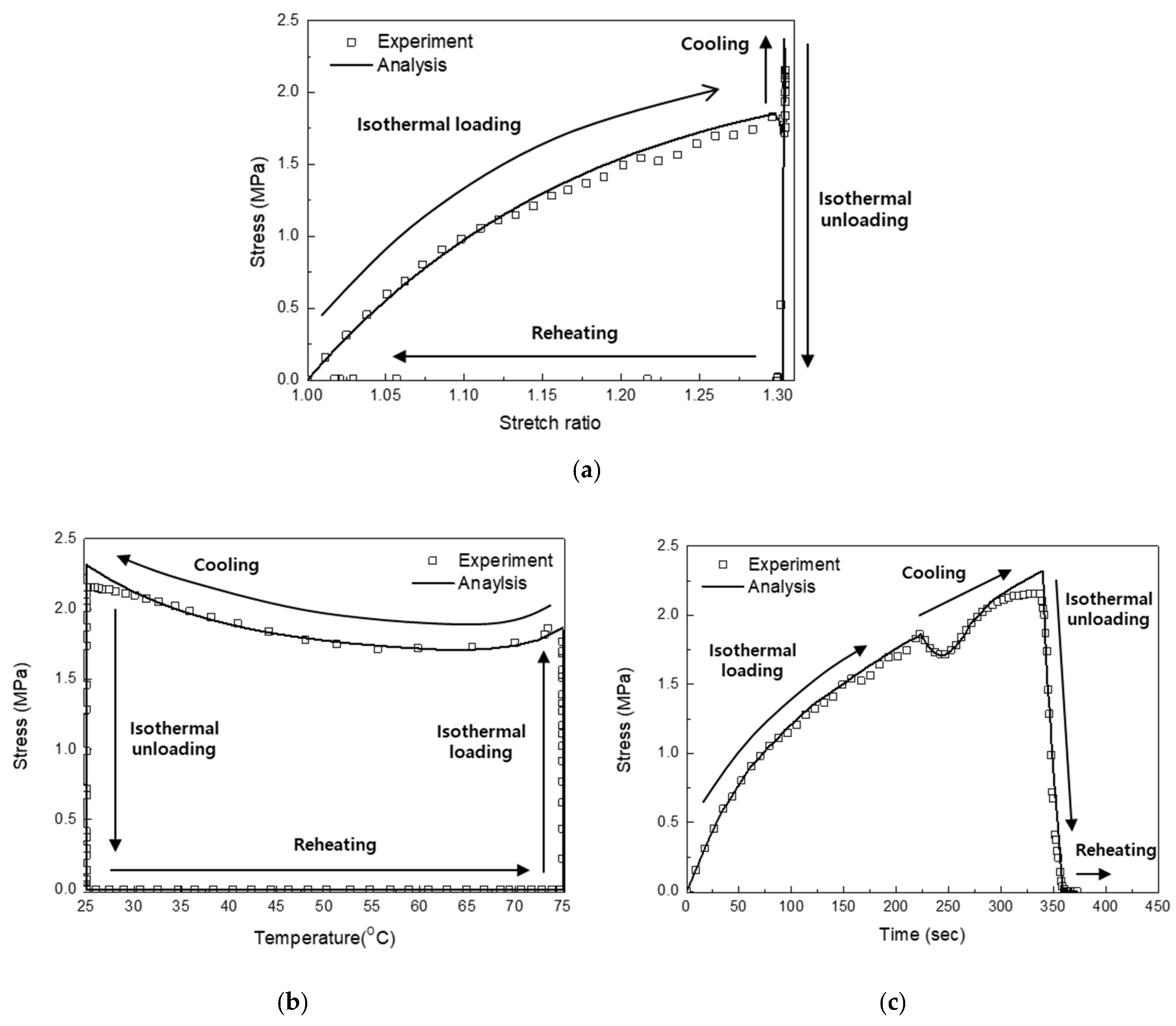
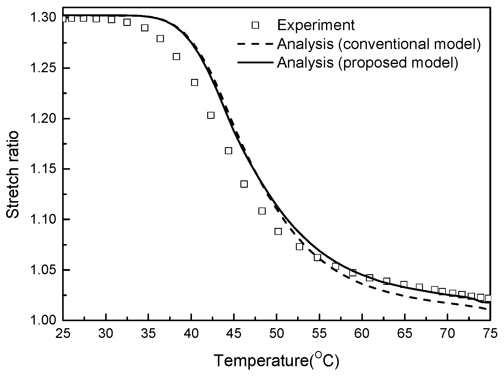
The thermomechanical cycle test is performed to investigate the shape recovery behavior of the SMCPs. The stress responses with respect to stretch ratio, time, and temperatures are illustrated in Figure 18. Initially, the specimen is stretched to a stretch ratio of 1.3 at 75 °C, applying a loading rate of 10 mm/min (isothermal loading). Subsequently, the temperature is lowered to 25 °C over a period of 100 s while maintaining the fixed deformed shape (cooling). Due to the temperature-dependent stiffness change, the stress increases by approximately 20% as the specimen cools. The specimen is unloaded at a constant rate of 10 mm/min while being held at a low temperature (isothermal unloading). During the reheating stage, the temperature is raised to 75 °C within 10 s, allowing the specimen to recover its original shape. The shape recovery response is analyzed by comparing the restored stretch ratios at various temperatures, as presented in Figure 19. As temperature rises, the release of stored strain energy enables the SMPC to return to its original configuration. Compared to neat SMPs, SMPCs demonstrated a higher recovery ratio, owing to the additional elastic energy stored in fabric reinforcement. However, approximately 6% of the original shape remained unrecovered, primarily due to hysteresis and residual deformation within the fabric layers. When the fabric is assumed to behave reversibly (as in conventional models), the recovery ratio falls below 3%. In contrast, the proposed model provided predictions that closely matched experimental observations and effectively represented the nonlinear effects associated with fabric behavior.
Since the stored strain is proportional to the rate of temperature change, the influence of cooling time is analytically examined (Figure 20). When the SMPCs are cooled to 25 °C within 2 s, the irrecoverable deformation is approximately 4.5% of the deformed shape. A similar residual deformation of 6% is observed when the cooling time is extended to 200 s. However, a significant increase in permanent deformation up to 17% is noted when the cooling time prolonged to 20,000 s. These results indicate that reducing the temperature within 200 s is sufficient to achieve effective shape fixitaion.

4. Numerical Study on SMPC Hinges

In this section, the shape recovery behaviors of SMPC hinges are numerically investigated using the developed constitutive equation. Section 4.1 shows the numerical model of a SMPC hinge under four-point bending load. Bending beahviors and recovered deformation with different temperature and time variables are presented in Section 4.2 and Section 4.3.

4.1. Numerical Model of SMPC Hinge

SMPC hinges, generally adapted to antenna or solar cell hinge mechanism in space applications, are exposed to bending load. Thus, the numerical model of SMPC hinge is conducted under a four-point bending condition as presented in Figure 21. It is assumed that the temperature of a SMPC hinge embedded with a layer of conductive fabric changes evenly. The fiber volume fraction is 0.01872 and the weft is arranged in the longitudinal direction. The geometric dimensions of the model are 160 mm (L), 40 mm (w), and 8 mm (t). One end of the SMPC hinge has a pin-supported boundary condition and the other end can move only in the longitudinal direction. The span length (LS) is 80 mm and a distributed load (P) of 1.125 N/mm is exerted to apply bending moment. The SMPC hinge is bent until the maximum deflection becomes 48 mm.

4.2. Bending Beahviors with Different Temperatures

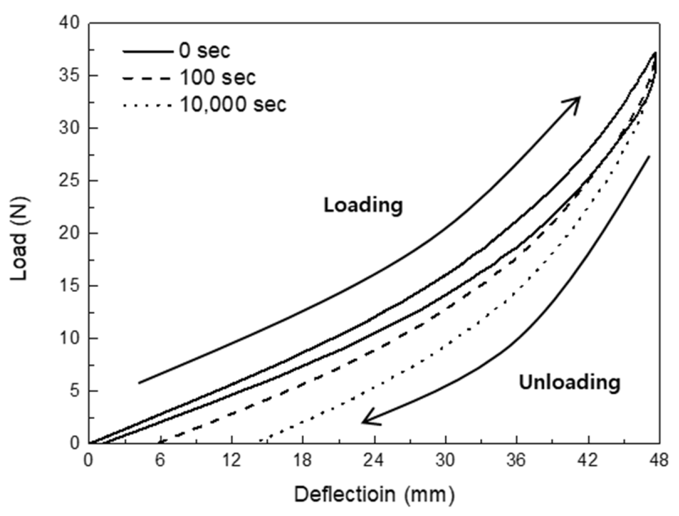
In order to verify the structural stability, the temperature-dependent bending characteristics of a SMPC hinge should be investigated. Bending behaviors are examined via bending analysis under a single loading–unloading condition as described in Figure 22. A SMPC hinge is deformed by applying bending moment (step 1). After unloading the bending moment (step 2), the elastic energy of the deformed beam is released. The analysis results at the temperatures of 25 °C and 75 °C are presented in Figure 23. The applied total force is 37.2 N and 7700 N at 75 °C and 25 °C, respectively. Because the stiffness of the SMPs is dominant at 25 °C, the deflection returns to zero while 24% of energy is dissipated after unloading. On the other hand, because the stiffness of the fabrics is prominently exhibited at 75 °C, irreversible deflection is shown while the energy dissipation ratio is 0.12. Under the assumption that the deformed hinge is stowed for a while at 75 °C, the effect of the stowing time on unloading behaviors is studied as presented in Figure 24. Due to the viscoelasticity of the SMPCs, the energy dissipation ratio increases to 0.119, 0.202, and 0.384 as the hinge is stored longer. The irreversible deflection is extended from 0.005 mm to 0.016 mm.

4.3. Shape Recovery Bhaviors with Different Time Variables

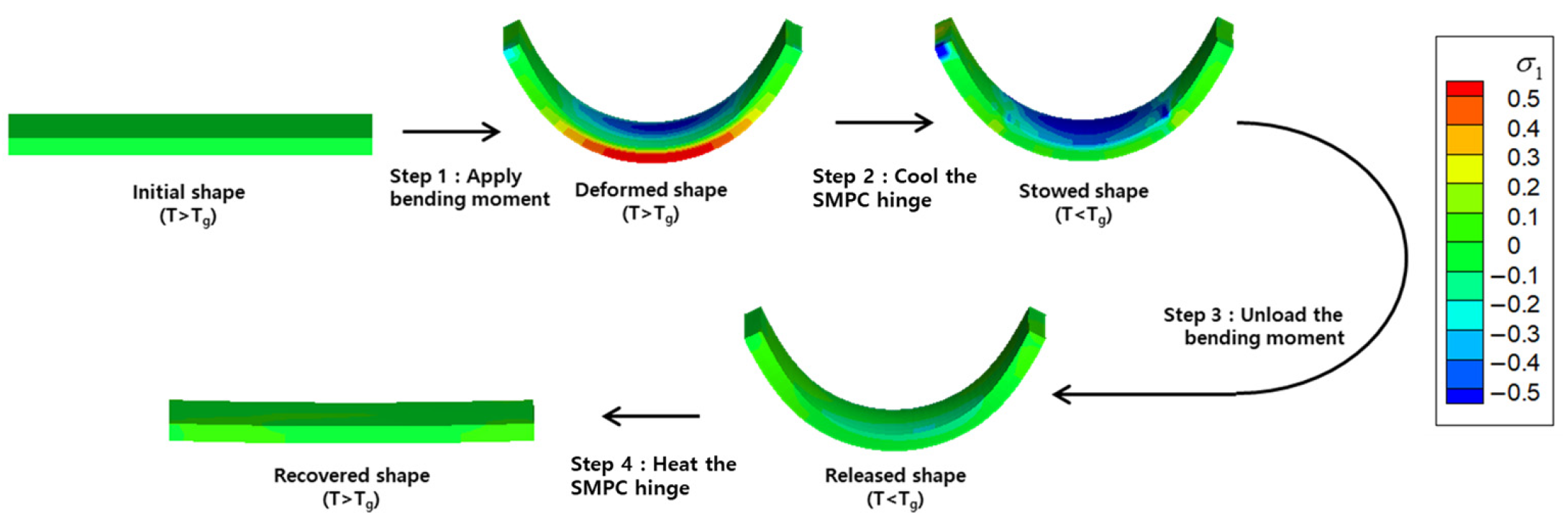
Figure 25 represents the loading conditions experienced by a SMPC hinge when the hinge is assembled on the ground and deployed in space, which are bending, stowed, residual stress-released, and shape recovery conditions. After the hinge is applied with bending moment at a temperature above Tg (step 1), the temperature decreases to fix the stowed configuration (step 2). During step 2, part of the elastic energy is stored. When the bending moment is eliminated (step 3), the remaining elastic energy of the hinge is released, and can maintain stowed shape without external force. By increasing the temperature, the hinge is deployed to initial shape as the stored energy is discharged (step 4).
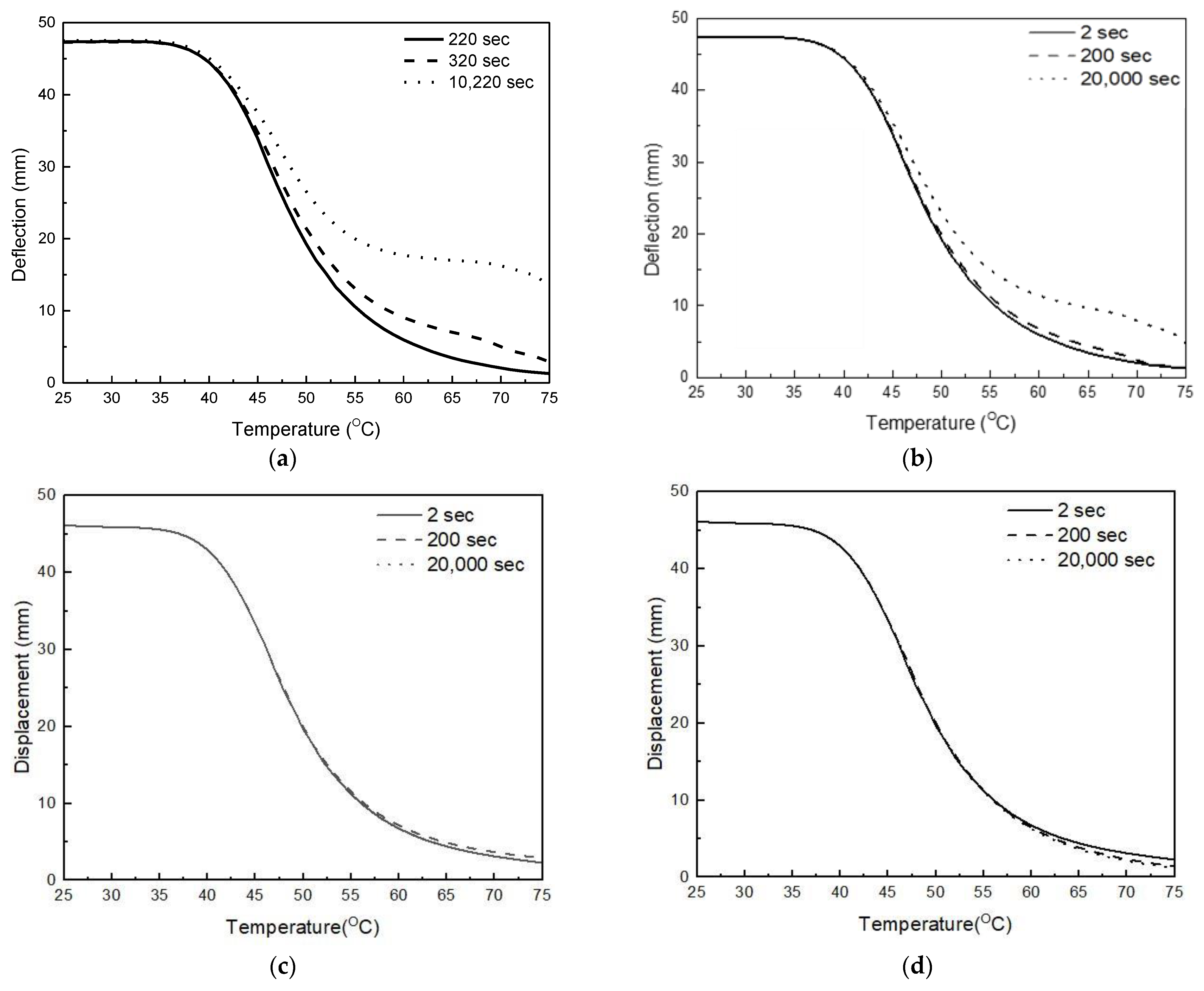
The relationship between the deflection and temperature during shape recovery of SMPC hinge with respect to four time variables that determine recovered deflection is presented in Figure 26. The hinge is bent until the deflection becomes 48 mm. Considering the solar array stowing process, the hinge is assumed to bend within 220 s (approx. 4 min) to 10,220 s (approx. 3 h). As the bending time increased, unrecovered deflection increased from 1.3 mm to 14 mm. At constant bending time, the stored strain energy is regarded as it depends on the cooling time. Based on the numerical simulation in Section 3.2.3, the recovered deflection is simulated as the cooling time increased from 2 s to over 200 s. When the cooling time is 20,000 s (approx. 5 h), it is predicted that the hinge will restore the deformed shape until the deflection becomes 5.8 mm. And it is expected that the unrestored deflection will be reduced to 1.3 mm by decreasing cooling time to 2 s. In contrast to bending and cooling time, stowed and reheating time show negligible effect on recovered deflection. It is because shape recovery energy is determined before the hinge cools down. As bending time increases, the load required to bend the hinge decreases due to viscoelastic effect, leading to a reduction in applied energy. During phase transition, where the applied energy is converted to stored energy in the cooling stage, the energy loss increases with longer cooling times.

5. Discussion

A novel constitutive equation for SMPCs is proposed, incorporating both the viscoelastic behavior of the SMP matrix and the energy dissipation characteristics of the conductive fabric reinforcement. To determine the model coefficients, a comprehensive experimental approach is employed, including uniaxial tensile, bias-extension, stress relaxation, DMA, and shape recovery tests. The hysteresis test on the fabric layers enables the determination of coefficients related to energy dissipation, which directly contributes to the overall accuracy of the model. The proposed constitutive equation demonstrates excellent agreement with experimental results, effectively predicting mechanical response of SMPCs varying with time and temperature. Notably, the consideration of residual strains and hysteresis effect in the model significantly improves its ability to predict the shape recovery behaviors of SMPCs. The bending characteristics of SMPC hinge under four-point bending is numerically investigated using the constitutive equation. The results indicate that both bending and cooling times play a crucial role in achieving high recovery ratios. Specifically, it is observed that when the hinge is cooled down for over 200 s, shape recovery ratio is decreased from 97% to 88%, demonstrating that prolonged cooling times reduce its ability to fully recover its shape. This finding underscores the importance of controlling cooling time to optimize performance, especially in applications requiring fast shape recovery. In contrast, stowed and reheating time show minimal impact on shape recovery. These characteristics highlight two significant advantages of using SMPC in space applications. First, SMPC hinges offer high deployment reliability, even when the hinge remains stowed on the ground for several weeks or months. This makes SMPCs highly suitable for space missions where long storage times are common before deployment. Second, SMPs help minimize shape error after deployment, even when subjected to long reheating periods in deep space, a critical factor for precision in space systems. Given these characteristics, SMPC hinges can provide a simpler, more reliable alternative to traditional mechanical deployment mechanisms, reducing both the complexity and mass of the system. However, challenges still remain, such as outgassing issues under vacuum conditions, degradation of mechanical properties, and shape recovery performance in thermal cycle environments. In the future, the shape recovery behaviors of SMPC hinges will be investigated experimentally following thermal vacuum and thermal cycling tests. In addition, methods to prevent mechanical property degradation of SMPC hinges under radiation exposure will be researched.

Author Contributions

Writing—original draft, O.-H.K.; Supervision, J.-H.R. All authors have read and agreed to the published version of the manuscript.

Funding

This research received no external funding.

Data Availability Statement

The original contributions presented in this study are included in the article. Further inquiries can be directed to the corresponding author.

Conflicts of Interest

Author O-Hyun Kwon was employed by the company LIG Nex1. The remaining authors declare that the research was conducted in the absence of any commercial or financial relationships that could be construed as a potential conflict of interest.

Abbreviations

The following abbreviations are used in this manuscript:
DMADynamic Mechanical Analysis
FEAFinite Element Analysis
SMPShape Memory Polymer
SMPCShape Memory Polymer Composite
TTSPTime–Temperature Superposition Principal
WLFWilliams–Landel–Ferry

References

  1. Liu, T.; Liu, L.; Yu, M.; Li, Q.; Zeng, C.; Lan, X.; Liu, Y.; Leng, J. Integrative hinge based on shape memory polymer composites: Materials, design, properties and application. Copmos. Struct. 2018, 206, 164–176. [Google Scholar] [CrossRef]
  2. Dao, T.D.; Ha, N.S.; Goo, N.S.; Yu, W.R. Design, fabrication, and bending test of shape memory polymer composite hinges for space deployable structures. J. Intell. Mater. Syst. Struct. 2018, 29, 1560–1574. [Google Scholar] [CrossRef]
  3. Liu, Z.; Lan, X.; Bian, W.; Liu, L.; Li, Q.; Liu, Y.; Leng, J. Design, material properties and performances of a smart hinge based on shape memory polymer composites. Compos. Part B Eng. 2020, 193, 108056. [Google Scholar] [CrossRef]
  4. Iorio, L.; Quadrini, F.; Santo, L.; Circi, C.; Cavallini, E.; Pellegrini, R.C. Shape memory polymer composite hinges for solar sails. Adv. Space Res. 2024, 74, 3201–3215. [Google Scholar] [CrossRef]
  5. Zeng, C.; Liu, Z.; Liu, L.; Zhao, W.; Xin, X.; Liu, Y.; Leng, J. Effect of prolonged isothermal exposure and thermal cycling on mechanical properties and shape recovery behavior of shape memory composites. Compos. Part A Appl. Sci. Manuf. 2025, 194, 108921. [Google Scholar] [CrossRef]
  6. Herath, M.; Epaarachchi, J.; Islam, M.; Fang, L.; Leng, J. Light activated shape memory polymers and composites: A review. Eur. Polym. J. 2020, 136, 109912. [Google Scholar] [CrossRef]
  7. Boudjellal, A.; Trache, D.; Khimeche, K.; Hafsaoui, S.L.; Bougamra, A.; Tcharkhtchi, A.; Durastanti, J.F. Simulation and reinforcement of shape-memory polymers and their composites: A review. J. Thermoplast. Compos. 2020, 35, 2227–2260. [Google Scholar] [CrossRef]
  8. Namathoti, S.; Rama Sreekanth, P.S. A review on progress in magnetic, microwave, ultrasonic responsive shape-memory polymer composites. Mater. Today Proc. 2022, 56, 1182–1191. [Google Scholar] [CrossRef]
  9. Sanaka, R.; Sahu, S.K.; Sreekanth, P.R.; Senthilkumar, K.; Bagdayan, N.D.; Siva, B.V.; Ma, Q. A review of the current state of research and future prospectives on stimulus-responsive shape memory polymer composite and its blends. J. Compos. Sci. 2024, 8, 324. [Google Scholar] [CrossRef]
  10. Rahman, A.A.; Ikeda, T.; Senba, A. Memory effects performance of polyurethane shape memory polymer composites (SMPC) in the variation of fiber volume fractions. Fibers Polym. 2017, 18, 979–986. [Google Scholar] [CrossRef]
  11. Herath, M.; Epaarachchi, J.; Islam, M.; Yan, C.; Zhang, F.; Leng, J. Effects of selectively triggered photothermal particles on shape memory polymer composites: An investigation on structural performance, thermomechanical characteristics and photothermal behavior. J. Intell. Mater. Syst. Struct. 2019, 30, 3124–3135. [Google Scholar] [CrossRef]
  12. Quadrini, F.; Iorio, L.; Bellisario, D.; Santo, L. Shape memory polymer composite unit with embedded heater. Smart Mater. Struct. 2021, 30, 075009. [Google Scholar] [CrossRef]
  13. Kim, C.L.; Lee, J.J.; Oh, Y.J.; Kim, D.E. Smart wearable heaters with high durability, flexibility, water-repellent and shape memory characteristics. Compos. Sci. Technol. 2017, 152, 173–180. [Google Scholar] [CrossRef]
  14. Sun, Y.; Chen, H.; Yin, H.; Sun, B.; Gu, B.; Zhang, W. A flexible, high-strength, conductive shape memory composite fabric based on continuous carbon fiber/polyurethane yarn. Smart Mater. Struct. 2020, 29, 085044. [Google Scholar] [CrossRef]
  15. Yadav, A.; Singh, S.K.; Das, S.; Kumar, S.; Kumar, A. Shape memory polymer and composites for space applications: A review. Polym. Compos. 2025. [Google Scholar] [CrossRef]
  16. Su, X.; Wang, Y.; Peng, X. An anisotropic visco-hyperelastic model for thermally-actuated shape memory polymer-based woven fabric-reinforced composteis. Int. J. Plast. 2020, 129, 102697. [Google Scholar] [CrossRef]
  17. Wang, Y.; Zhou, H.; Liu, Z.; Peng, X.; Zhou, H. A 3D anisotropic visco-hyperelastic constitutive model for unidirectional continuous fiber reinforced shape memory composites. Polym. Test. 2022, 114, 107712. [Google Scholar] [CrossRef]
  18. Qi, Y.; Huang, S.; Zhang, H.; Gu, B.; Sun, B.; Zhang, W. Shape memory behaviors of three-dimensional five-directional braided composites with different axial yarns arrangements. Compos. Struct. 2024, 338, 118105. [Google Scholar] [CrossRef]
  19. Hong, S.B.; Jang, J.H.; Park, H.; Kim, J.G.; Goo, N.S.; Yu, W.R. Three-dimensional constitutive model of woven fabric-reinforced shape memory polymer composites considering thermal residual stress. Smart Mater. Struct. 2019, 28, 035023. [Google Scholar] [CrossRef]
  20. Al Azzawi, W.; Epaarachchi, J.A.; Islam, M.; Leng, J. Implementation of a finite element analysis procedure for structural analysis of shape memory behavior of fibre reinforced shape memory polymer composites. Smart Mater. Struct. 2017, 26, 125002. [Google Scholar] [CrossRef]
  21. Gu, J.; Leng, J.; Sun, H.; Zeng, H.; Cai, Z. Thermomechanical constitutive modeling of fiber reinforced shape memory polymer composites based on thermodynamics with internal state variables. Mech. Mater. 2019, 130, 9–19. [Google Scholar] [CrossRef]
  22. Denis, Y.; Guzman-Maldonado, E.; Hamila, N.; Colmars, J.; Morestin, F. A dissipative constitutive model for woven composite fabric under large strain. Compos. Part A Appl. Sci. Manuf. 2018, 105, 165–179. [Google Scholar] [CrossRef]
  23. Denis, Y.; Hamila, N.; Itskov, M.; Guzman-Maldonado, E.; Morestin, F. A dissipative model for deep-drawing simulations: Elastic springback prediction and incremental forming strategies. Compos. Part A Appl. Sci. Manuf. 2021, 149, 106547. [Google Scholar] [CrossRef]
  24. Gupta, M.; Singh, H.; Khan, A.N.; Mahajan, P.; Prabhakaran, R.D.; Alagirusamy, R. An improved orthotropic elasto-plastic damage model for plain woven composites. Thin-Walled Struct. 2021, 162, 107598. [Google Scholar] [CrossRef]
  25. Dib, W.; Bles, G.; Blaise, A.; Tourabi, A. Modelling of cyclic visco-elasto-plastic behavior of coated woven fabrics under biaxial loading and finite strain. Int. J. Solids Struct. 2018, 154, 147–167. [Google Scholar] [CrossRef]
  26. Guo, S.; Wang, L.; Shao, G.; Shao, H.; Jiang, J.; Chen, N. Mechanical behavior and energy dissipation of woven and wrap-knitted pvc membrane materials under multistage cyclic loading. Polymers 2022, 14, 1666. [Google Scholar] [CrossRef] [PubMed]
  27. Spencer, A.J.M. Constitutive theory for strongly anisotropic solids. In Continuum Theory of the Mechanics of Fibre-Reinforced Composites; Springer: Dordrecht, The Netherlands, 1984; pp. 1–32. [Google Scholar]
  28. Aimenee, Y.; Vidal-Salle, E.; Hagege, B.; Sidoroff, F.; Boisse, P. A hyperelastic approach for composite reinforcement large deformation analysis. J. Copmos. Mater. 2010, 44, 5–26. [Google Scholar] [CrossRef]
  29. Charmetant, A.; Orliac, J.G.; Vidal-Salle, E.; Boisse, P. Hyperelastic model for large deformation analyses of 3D interlock composite preforms. Compos. Sci. Technol. 2012, 72, 1352–1360. [Google Scholar] [CrossRef]
  30. Peng, X.; Guo, Z.; Du, T.; Yu, W.R. A simple anisotropic hyperelastic constitutive model for textile fabrics with application to forming simulation. Compos. B Eng. 2013, 52, 275–281. [Google Scholar] [CrossRef]
  31. Yao, Y.; Huang, X.; Peng, X.; Liu, P.; Youkun, G. An anisotropic hyperelastic constitutive model for plain weave fabric considering biaxial tension coupling. Text. Res. J. 2019, 89, 434–444. [Google Scholar] [CrossRef]
  32. Gong, Y.; Peng, X.; Yao, Y.; Guo, Z. An anisotropic hyperelastic constitutive model for thermoplastic woven composite prepregs. Compos. Sci. Technol. 2016, 128, 17–24. [Google Scholar] [CrossRef]
  33. Mansouri, M.R.; Fuchs, P.F.; Criscione, J.C.; Schrittesser, B.; Beter, J. The contribution of mechanical interactions to the constitutive modeling of fiber-reinforced elastomers. Eur. J. Mech. A Solids 2021, 85, 104081. [Google Scholar] [CrossRef]
  34. Harrison, P.; Clifford, M.F.; Long, A.C. Shear characterization of viscous woven textile composites: A comparison between picture frame and bias extension experiments. Compos. Sci. Technol. 2004, 64, 1453–1465. [Google Scholar] [CrossRef]
  35. Cao, J.; Akkerman, R.; Boisse, P.; Chen, J.; Cheng, H.S.; De Graaf, E.F.; Gorczyca, J.L.; Harrison, P.; Hivet, G.; Launay, J.; et al. Characterization of mechanical behavior of woven fabrics: Experimental methods and benchmark results. Compos. A Appl. Sci. Manuf. 2008, 39, 1037–1053. [Google Scholar] [CrossRef]
  36. Bergmann, T.; Heimbs, S.; Maier, M. Mechanical properties and energy absorption capability of woven fabric composites under ±45 off-axis tension. Compos. Struct. 2015, 125, 362–373. [Google Scholar] [CrossRef]
  37. Li, Z.; Zhou, H.; Wang, Y.; Zhou, H.; Peng, X. Modelling energy dissipation and hysteresis of woven fabrics with large deformation under single loading-unloading cycle. Compos. Struct. 2022, 279, 114781. [Google Scholar] [CrossRef]
  38. Huang, B.; Zhou, H.; Wang, J.; Yu, T.; Peng, X.; Zhou, H. A mesoscopic constitutive model for woven fabrics with large deformation. Text. Res. J. 2024, 94, 136–151. [Google Scholar] [CrossRef]
  39. Holzapfel, G.A. Nonlinear Solid Mechanics: A Continuum Approach for Engineering Science; John Wiley & Sons: Hoboken, NJ, USA, 2000. [Google Scholar]
  40. Mooney, M. A theory of large elastic deformation. J. Appl. Sci. 1940, 11, 582–592. [Google Scholar] [CrossRef]
  41. Butaud, P.; Ouisse, M.; Jaboviste, K.; Placet, V.; Foltete, E. Dynamical mechanical thermal analysis of shape-memory polymers. In Shape Memory Polymers, Blends and Composites; Springer: Singapore, 2020; pp. 129–515. [Google Scholar]
  42. Williams, M.L.; Landel, R.F.; Ferry, J.D. The temperature dependence of relaxation mechanisms in amorphous polymers and other glass-forming liquids. J. Am. Chem. Soc. 1995, 77, 3701–3707. [Google Scholar] [CrossRef]
  43. Liu, Y.; Grall, K.; Dunn, M.L.; Greenberg, A.R.; Diani, J. Thermomechanics of shape memory polymers: Uniaxial experiments and constitutive modeling. Int. J. Plast. 2006, 22, 279–313. [Google Scholar] [CrossRef]
  44. ASTM D638; Standard Test Method for Tensile Properties of Plastics. ASTM International: West Conshohocken, PA, USA, 2014.
  45. ASTM D4065; Standard Practice for Plastics: Dynamic Mechanical Properties: Determination and Report of Procedures. ASTM International: West Conshohocken, PA, USA, 2012.
  46. ASTM D3039; Standard Test Method for Tensile Properties of Polymer Matrix Composite Materials. ASTM International: West Conshohocken, PA, USA, 2017.
Figure 1. Schematic of a one-dimensional rheological model for SMP matrix.
Aerospace 12 00717 g001
Figure 2. Description of directional alignment of fibers in fabric.
Aerospace 12 00717 g002
Figure 3. Shape memory polymers (SMPs) uniaxial test: (a) Prepared specimen; (b) experimental configuration.
Aerospace 12 00717 g003
Figure 4. Stress–stretch ratio characteristics under varying temperature conditions.
Aerospace 12 00717 g004
Figure 5. Uniaxial characteristics for shape memory polymers (SMPs).
Aerospace 12 00717 g005
Figure 6. Temperature dependence of shift factors.
Aerospace 12 00717 g006
Figure 7. Flexural modulus master curve over the frequency range.
Aerospace 12 00717 g007
Figure 8. Temperature dependence of frozen fractions.
Aerospace 12 00717 g008
Figure 9. Fabric uniaxial, bias-extension, and stress relaxation tests: (a) Prepared specimen; (b) Experimental configuration.
Aerospace 12 00717 g009
Figure 10. Warp direction uniaxial tensile response at varying temperatures.
Aerospace 12 00717 g010
Figure 11. Tensile response under uniaxial loading in both weft and warp directions.
Aerospace 12 00717 g011
Figure 12. Shear stress variation with respect to fiber angle change.
Aerospace 12 00717 g012
Figure 13. Stress relaxation response in both weft and warp directions.
Aerospace 12 00717 g013
Figure 14. Stress–stretch ratio relationship from hysteresis tests on fabrics: (a) in the weft direction; (b) in the warp direction.
Aerospace 12 00717 g014
Figure 15. Fabricated SMPC specimen.
Aerospace 12 00717 g015
Figure 16. Mechanical testing for SMPCs: (a) Experimental setup; (b) Surface temperature distribution.
Aerospace 12 00717 g016
Figure 17. Evaluation of thermo-viscoelastic properties of SMPCs: (a) Uniaxial tensile behavior at varying temperatures; (b) Time-dependent stress reduction at 75 °C.
Aerospace 12 00717 g017
Figure 18. Thermomechanical cycle response of SMPCs (R2 = 0.995, RMSE = 0.053 MPa): (a) Stress–stretch ratio relationship; (b) Stress–temperature relationship; (c) Stress–time relationship.
Aerospace 12 00717 g018
Figure 19. Recovered stretch ratio of SMPCs versus temperature.
Aerospace 12 00717 g019
Figure 20. Recovered stretch ratio depending on cooling time.
Aerospace 12 00717 g020
Figure 21. Numerical model of SMPC hinge four-point bending.
Aerospace 12 00717 g021
Figure 22. Bending behaviors of SMPC hinge.
Aerospace 12 00717 g022
Figure 23. Hysteresis effect analysis results: relationship between the load and deflection (a) at 25 °C and (b) at 75 °C.
Aerospace 12 00717 g023
Figure 24. Comparison of unloading behaviors depending on the stowing time.
Aerospace 12 00717 g024
Figure 25. Shape recovery behaviors of a SMPC hinge.
Aerospace 12 00717 g025
Figure 26. Relationship between the deflection and temperature during shape recovery with respect to (a) bending time, (b) cooling time, (c) stowed time, (d) and reheating time.
Aerospace 12 00717 g026
Table 1. Definition of the test methods for characterizing SMPs.
CharacteristicsTest MethodsCoefficients
HyperelasticityTensileC10, C01
ViscoelasticityDMAβi, τi, c1, c2, Tg
Shape recoveryThermomechanical cycleT0, h, s
Thermal expansionIncreasing temperaturea, b, c
Table 2. Definition of the test methods for characterizing fabrics.
CharacteristicsTest MethodsCoefficients
Tensile propertyTensile (0°, 90°)k1, k2, k3, k4, k5, k6
Hysteresis effectLoding-unloadingk1, k2, k3, k4, k5, k6
ViscoelasticityStress relaxationβi, τi
Shear propertyTensile (±45°)k7, k8, k9
Table 3. Hyperelasticitiy model coefficients for shape memory polymers.
CharacteristicsTemperature (°C)C10 (MPa)C01 (MPa)
Hyperelasticity25−40754356
35−11451230
45−3.0175.263
55−1.1362.123
75−0.3791.030
Table 4. Viscoelasticity model coefficients for shape memory polymers.
Characteristicsiβi (-)τi (s)
Viscoelasticity10.1070.0154
20.1602.57
30.235213
40.2689580
50.193202,000
Table 5. WLF equation coefficients for shape memory polymers.
CharacteristicsC1 (-)c2 (°C)Tg (°C)
Williams–Ladnel–Ferry (WLF) equation52.433166.42945
Table 6. Coefficients for the tensile properties of fabrics.
Characteristicsk1 (MPa)k2 (MPa)k3 (MPa)k4 (MPa)k5 (MPa)k6 (MPa)
Tensile0.0135−0.01870.0545−0.07820.28590.2618
Table 7. Coefficients for the shear properties of fabrics.
Characteristicsk7 (MPa)k8 (MPa)k9 (MPa)
Shear0.7401−0.55310.2107
Table 8. Coefficients for the viscoelasticity properties of fabrics.
Characteristics Weft DirectionWarp Direction
iβi (-)τi (s)βi (-)τi (s)
Viscoelasticity10.035932.7110.0325716.31
20.1284820.980.0073716.49
30.05779164.80.937123681
Table 9. Coefficients for the hysteresis properties of fabrics.
Characteristicsk1 (MPa)k2 (MPa)k3 (MPa)k4 (MPa)k5 (MPa)k6 (MPa)
Hysteresis
(Unloading)
0.05370.00440.01741.1946−0.72870.2250
Disclaimer/Publisher’s Note: The statements, opinions and data contained in all publications are solely those of the individual author(s) and contributor(s) and not of MDPI and/or the editor(s). MDPI and/or the editor(s) disclaim responsibility for any injury to people or property resulting from any ideas, methods, instructions or products referred to in the content.