ROS-Based Multi-Domain Swarm Framework for Fast Prototyping
Abstract
1. Introduction
- Scalability: A modular design that supports the seamless addition of new platforms and payloads.
- Interoperability: Integration with open-source tools and protocols, ensuring compatibility across robotic systems.
- Autonomy: Advanced decision-making algorithms for collision avoidance, dynamic mission planning, and target reallocation.
Methodology
2. Architecture
- Facilitating the transfer and reception of data (such as telemetry and commands) among the other nodes.
- Establishing the decision-making for several coordinated missions.
- Executing missions based on the vehicle’s type to effectively accomplish diverse objectives.
2.1. General Hardware Architecture of the System
- Autopilot: Responsible for executing vehicle movement commands, and communicates with the companion computer via MAVLink protocol.
- Mesh radiomodem: Establishes communication with other nodes in the swarm. Uses a decentralized ad hoc network for efficient data exchange.
- Companion computer: Executes high-level swarm logic. Hosts the ROS-based software modules for task management and inter-node communication.
- Payload radiomodem: In charge of sending the payload information, video, and metadata, and also for the control of the high-bandwidth payload systems.
2.2. General Software Architecture of the System
- MAVROS: Facilitates communication with the autopilot using the MAVLink protocol.
- Vehicle Monitoring: Monitors vehicle status and security parameters, generating alerts for anomalies.
- Swarm Manager: Detects new nodes, manages active nodes, and ensures synchronization across the swarm.
- State Machine: Governs mission execution through three primary states: Planning, On Mission, and Emergency.
- Mission Manager: Assigns tasks to nodes, monitors mission progress, and supports dynamic replanning.
- Collision Avoidance: Prevents inter-vehicle collisions through altitude adjustments and route modifications.
- Swarm Interface: Manages communication between nodes, enabling decentralized coordination.
- Device Configuration: Handles the setup of hardware components such as autopilots and radiomodems.
2.3. Architecture of the Modules
- Common modules that are shared across all projects in the swarm system.
- CommsSystem consists of the communication modules, device setup, and the communication interface that connects the swarm with the radio frequency elements.
- GroundSystem incorporates a node that is capable of receiving ADS-B signals in order to determine the positions of other aircraft.
- SwarmSystem comprises the anti-collision, mission manager, state machines, and swarm manager packages.
2.3.1. Swarm Database
- Systems: Consolidates all vehicle-related data and comprises seven tables:
- ○
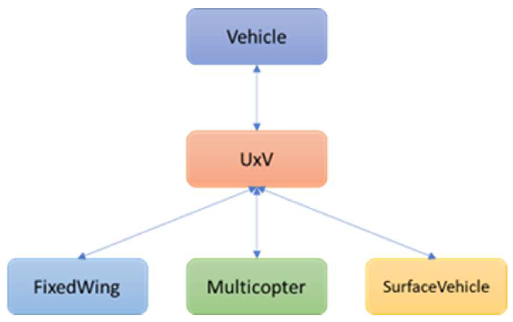
- Classification system: Vehicles are categorized into three tiers: type, subtype, and model. The topmost level of the hierarchy is encompassed within the type table. For instance, it includes UAVs, UGVs, or Unmanned Surface Vehicles, as shown in Figure 3.
- ○
- System subtypes: Includes all variations or categories of systems. Each subtype is linked to a specific category of vehicle, such as UAVs or UGVs. Within the subcategories of UAVs, many types may be identified, such as fixed-wing, quadrotor, and rover.
- ○
- System model: Encompasses all system models, including fixed-wings, Vertical Take-Off and Landing (VTOL), multicopters, helicopters, and Ground Control Stations (GCS). Every model is linked to a specific vehicle subtype. Thus, a specific model is directly associated with a singular subtype, which in turn is linked to a singular type.
- ○
- System layouts: This table serves as a foundation for producing additional replicas of vehicles with identical attributes. The composition of this consists of two parameters: the specific model of the vehicle and the particular type of payload that is fitted. Thus, a system template is established, which will subsequently be utilized to generate several copies of the identical system.
- ○
- System model parameters: This table encompasses all the parameters associated with a model, including, for example, the loiter radio and the presence of a parachute.
- ○
- Systems: Each system is associated with a tangible entity. Thus, they are entities linked to system templates (system layouts). By employing this method, it is possible to build several vehicles that possess identical attributes. The table consists of a user-defined ID and template, with each generated vehicle being internally allocated a distinct ID. It is important to mention that duplicating the same user ID and layout is not allowed. It is not possible to have two models with the same name; each model must be unique.
- ○
- System parameters refer to the specific parameters that are linked to the vehicle itself, for instance, the UDEV wiring regulations and MAC address.
- Swarm: Consolidates all the data pertaining to the swarm and is categorized into four tables:
- ○
- Missions: Includes many categories of swarm missions, including target, area, perimeter, and more.
- ○
- Mission parameters: Encompasses all the variables and criteria associated with the missions.
- ○
- Modules: Includes various swarm modules, such as the anti-collision module designed for fixed-wing vehicles and the anti-collision module specifically designed for quadcopters.
- ○
- Module parameters: Contains all the essential parameters required for the functioning of the swarm modules.
- Payload: Consolidates all data pertinent to the payload, arranged into twelve tables:
- ○
- Payload type: A three-level framework has been established to classify payloads, analogous to the system hierarchy. The payload type pertains to the highest classification and encompasses instances such as attack, radio frequency, sound, etc.
- ○
- Payload subtype: The subtype is a hierarchical classification beneath the primary type. Loitering munition, effector, and turret are classifications of attack.
- ○
- Payload model: The model represents the ultimate tier and is contingent upon the subtype. Loitering munitions are categorized into light, medium, and heavy varieties.
- ○
- Gimbal Axis Parameters: Encompasses all parameters related to each gimbal axis (roll, tilt, and pan).
- ○
- Gimbal configurations: This table functions as a foundation for producing further replicas of gimbals with identical attributes. It consists of five parameters: baud rate, period, pan axis parameter, tilt axis parameter, and roll axis parameter.
- ○
- Sensors: Comprises many sensor types including IR, Lidar, and camera, among others.
- ○
- Sensor parameters: Includes all sensor specifications, such as horizontal field of view (HFOV), vertical field of view (VFOV), resolution, etc.
- ○
- Payload layouts: This table functions as a foundation for producing further iterations of payloads with identical attributes. It comprises two parameters: the gimbal configuration and the attack type (e.g., a two-axis gimbal + software defined radio (SDR)).
- ○
- Payloads: These are replicas of the payload layouts table. This is designed to produce many payloads with identical attributes. The table contains the user ID and its configuration, with each payload allocated a distinct internal ID. The identical user ID and layout combination cannot be duplicated.
- ○
- Payload parameters: Distinctive parameters of each payload, including interfaces, protocols, etc.
- ○
- Autodetection class: Comprises all classes that the autodetection module is capable of identifying, including individuals, vehicles, etc.
- ○
- Motor: Includes the type of motorization used in the gimbal, servos, brushless, etc.
- Common: Consolidates all the shared data from prior models and comprises six tables:
- ○
- Layout of Onboard Computer: A table comprising various sorts of companion computers, such as Raspberry Pi, NVIDIA Jetson.
- ○
- Communication systems: Includes the IP addresses used for establishing communication with the microhard.
- ○
- Corrections: This table consists of four columns. The initial column represents the bug ID, the second column indicates the module from which the bug is reported, the third column provides a description of the bug problem, and the final column denotes the level of criticality. The ground interface visually represents faults using different colors according to their level of criticality.
- ○
- PID controllers: This table displays the numerical values of the PID controllers for the gimbal. These terms consist of the proportional, derivative, and integral components. Additionally, there is the maximum cumulative error of the integral term and a Boolean variable for anti-windup.
2.3.2. Vehicle Monitoring
2.3.3. Swarm Manager
- Creates the VehicleInfo message from the SwarmStatus, UAVExtraInfo, and VehicleStatus messages.
- Manages the list of vehicles and connected GCSs, controlling which of them is active.
- Checks if it is correct to send a mission to the state machine. The mission will be rejected in the following cases:
- ○
- Home position is not defined;
- ○
- The vehicle status is not ready;
- ○
- When the mission does not affect the vehicle, because the vehicle is not in the fleet or on the mission list.
2.3.4. State Machine
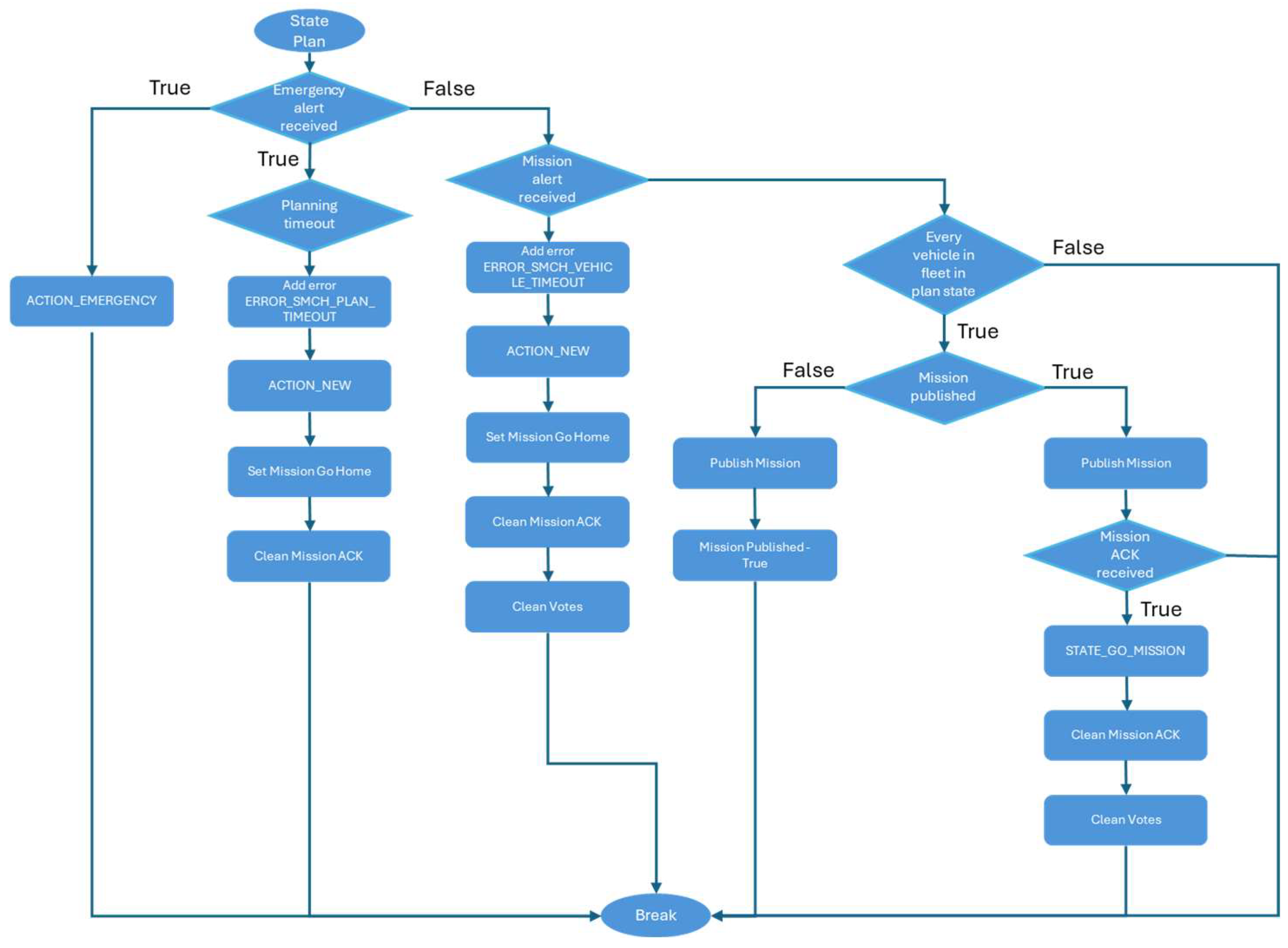
- The StateMachine, where the transitions take place.
- The CommandManager, which receives missions from the swarm_manager module and activates operations that facilitate transitions between states.
- STATE_PLAN: In this state, the mission is assigned to the mission module under the requirement that all vehicles in the newly formed fleet are in an identical state. Upon reaching the specified condition, it is necessary to have a confirmation message to execute a state transition. In the event of inadequate planning, an alert is triggered and the vehicle is removed from the fleet, returning to its original place. To avoid the state machine from becoming unresponsive, an event is generated when it remains in that state for an extended period. A timer triggers this event and instructs the vehicle to cease floating and return to its home location.
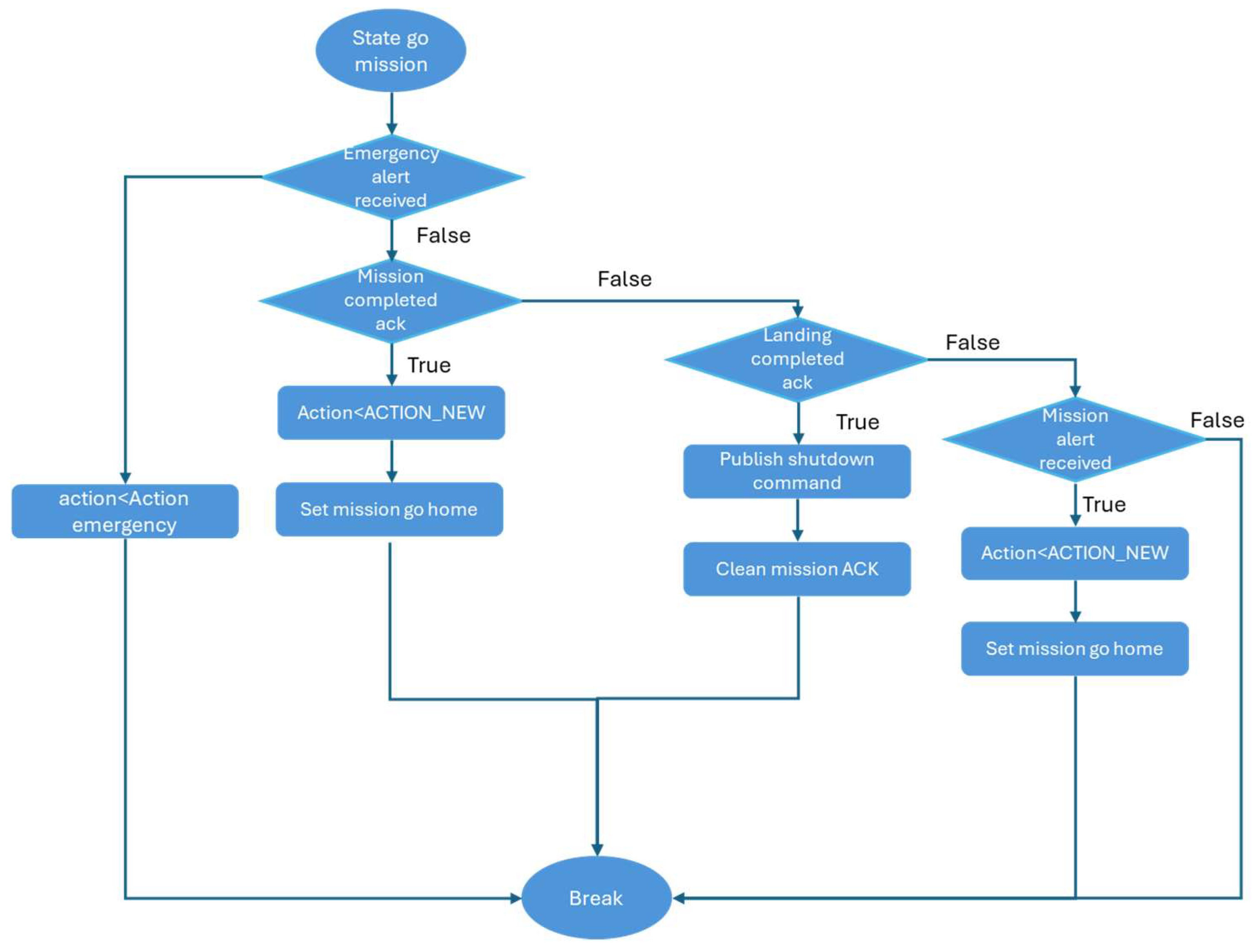
- STATE_GO_MISSION: This state refers to the vehicle actively carrying out its assigned task. A case study is as follows:
- ○
- The vehicle monitoring system receives an alert instructing it to switch to emergency action.
- ○
- Upon receiving a mission complete ack, the vehicle remains in the fleet and returns to its base.
- ○
- A landing ack is received, indicating that the state machine has been deactivated.
- ○
- An alarm is received from other modules, indicating that the vehicle has departed from the fleet and returned to the base.
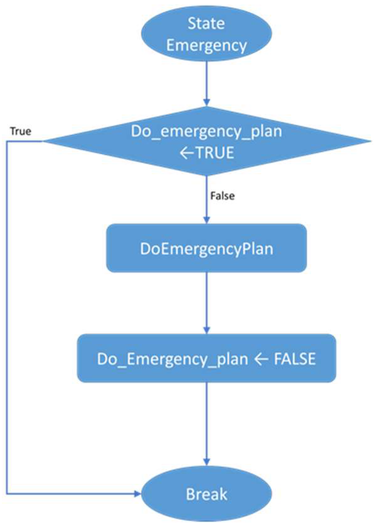
- STATE_EMERGENCY: In the event of an alert being received from the vehicle monitoring module, an emergency protocol is enacted. This module directs the essential actions to be executed for the specified emergency.
- ACTION_NONE: The action that is automatically taken as the default option. This action does not result in any alteration of the current state.
- ACTION_READY: Upon system initialization, the state machine module must await confirmation from the vehicle monitoring module that the vehicle has been started correctly. Upon occurrence of this event, the action results in a transition to the STATE_GO_MISSION.
- ACTION_NEW: This action transitions the state to STATE_PLAN.
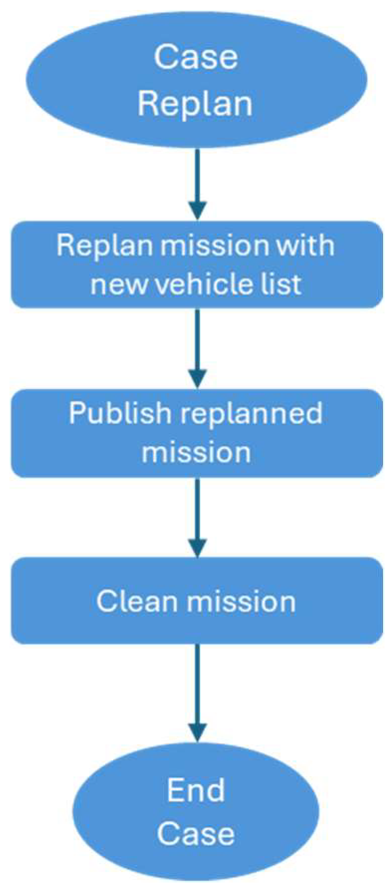
- ACTION_REPLAN: This action transitions the state to STATE_PLAN.
- ACTION_EMERGENCY: This action transitions the state to STATE_EMERGENCY.
- Mission Complete ACK: The necessary action has been taken regarding ACTION_NEW and a mission has been assigned to each fleet identifier for maintenance.
- Landing Acknowledgement Completed: A command to shut down and a confirmation of mission completion are delivered.
- Mission alert received: The action has been updated to ACTION_NEW, and a mission to return home is given, abandoning the existing fleet.
2.3.5. Mission Manager
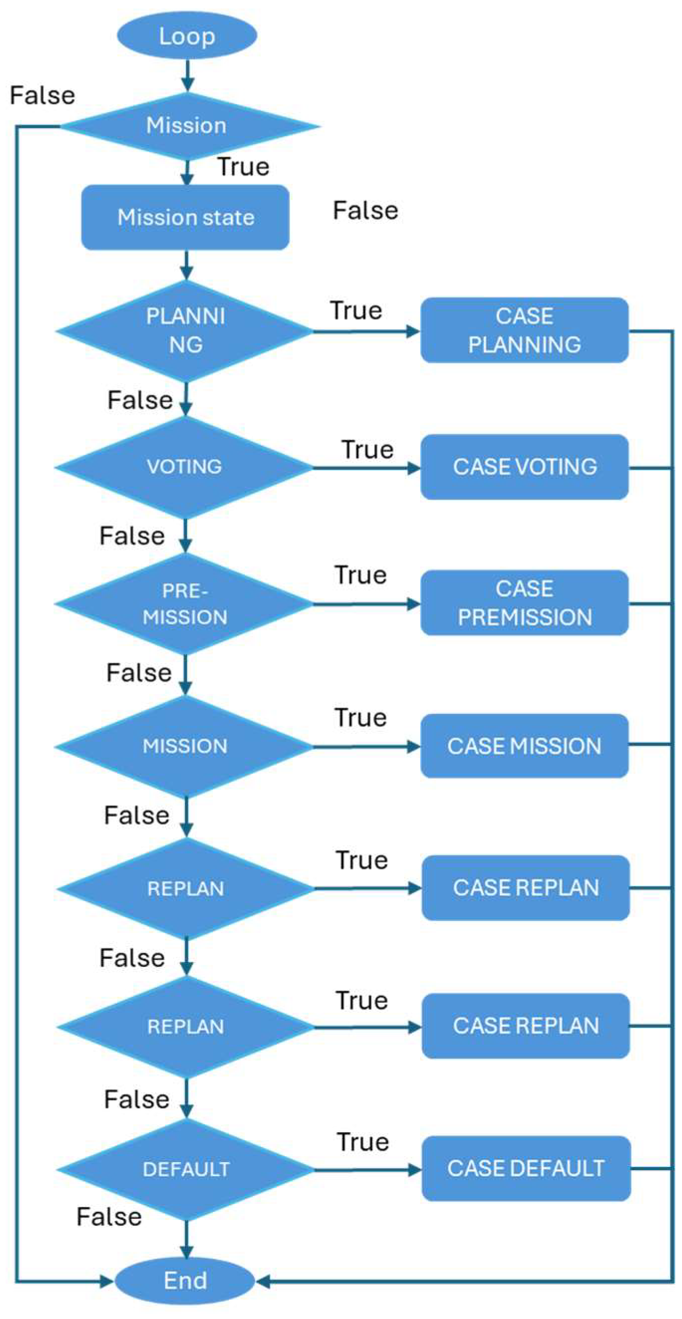
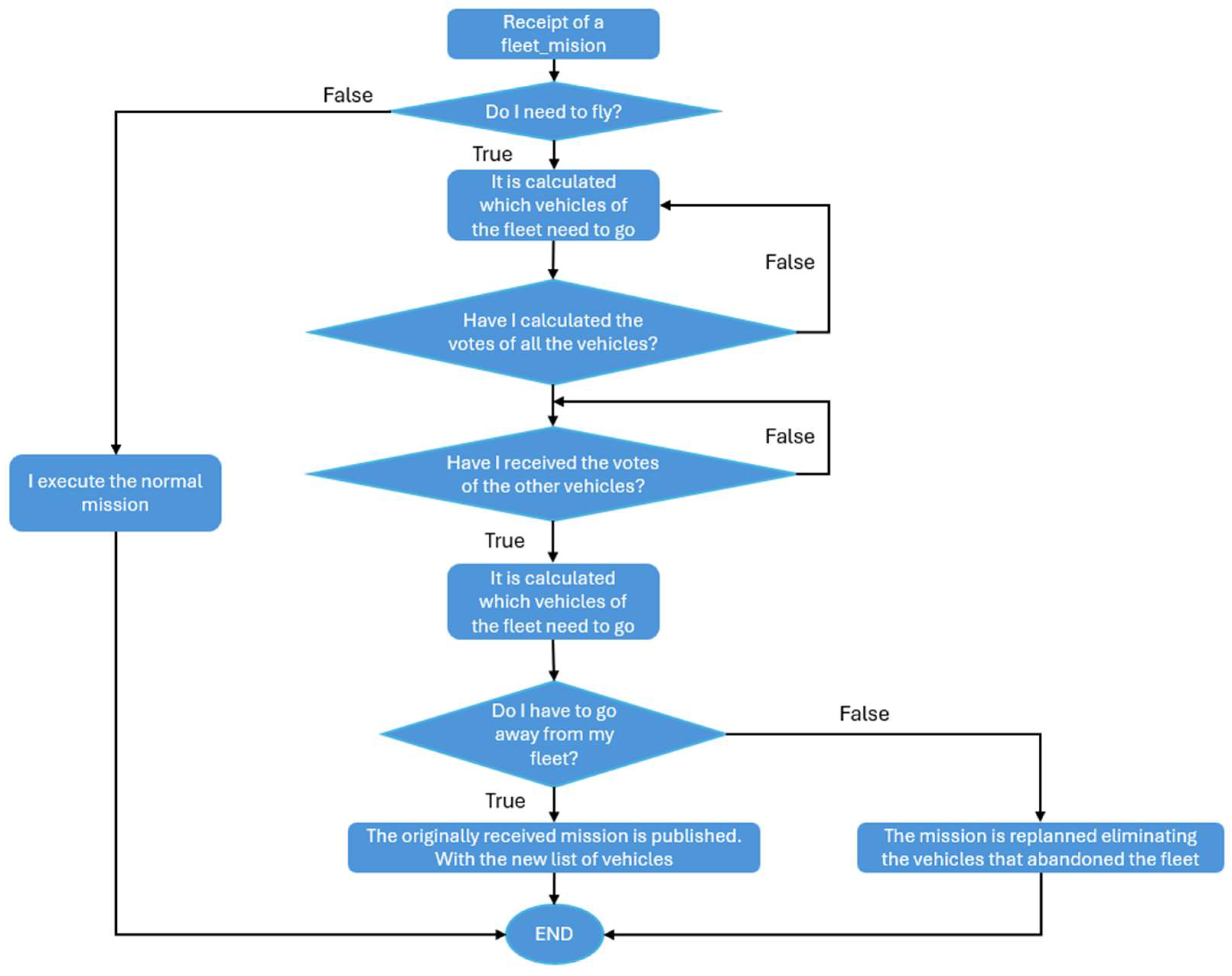
- MISSION_STATE_PLANNING: This state involves the computation of mission routes based on the number of vehicles needed for the mission. The assignment of each route to each aircraft is determined through a voting process, assuming the planning is accurate.
- MISSION_STATE_VOTING: After all votes are received, they are tallied and the designated route is transmitted to the autopilot.
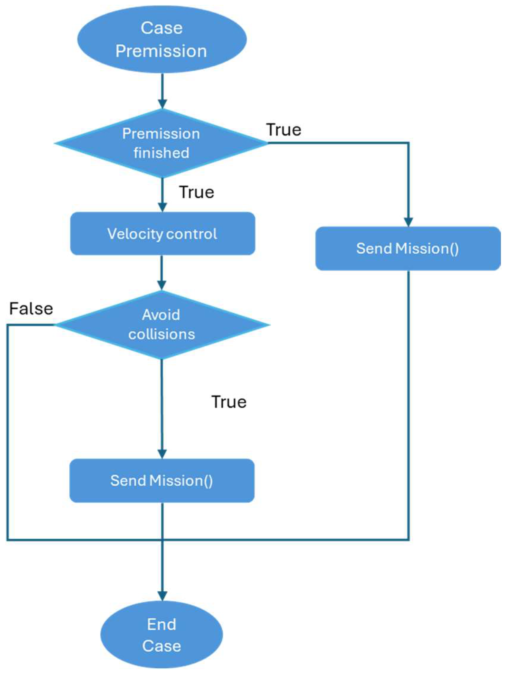
- MISSION_STATE_PREMISSION: This state specifically applies to missions that necessitate permission. This implies that a Dubins path must be computed for each vehicle, and once transmitted to the autopilot, an airspeed control is executed for each Dubins path.
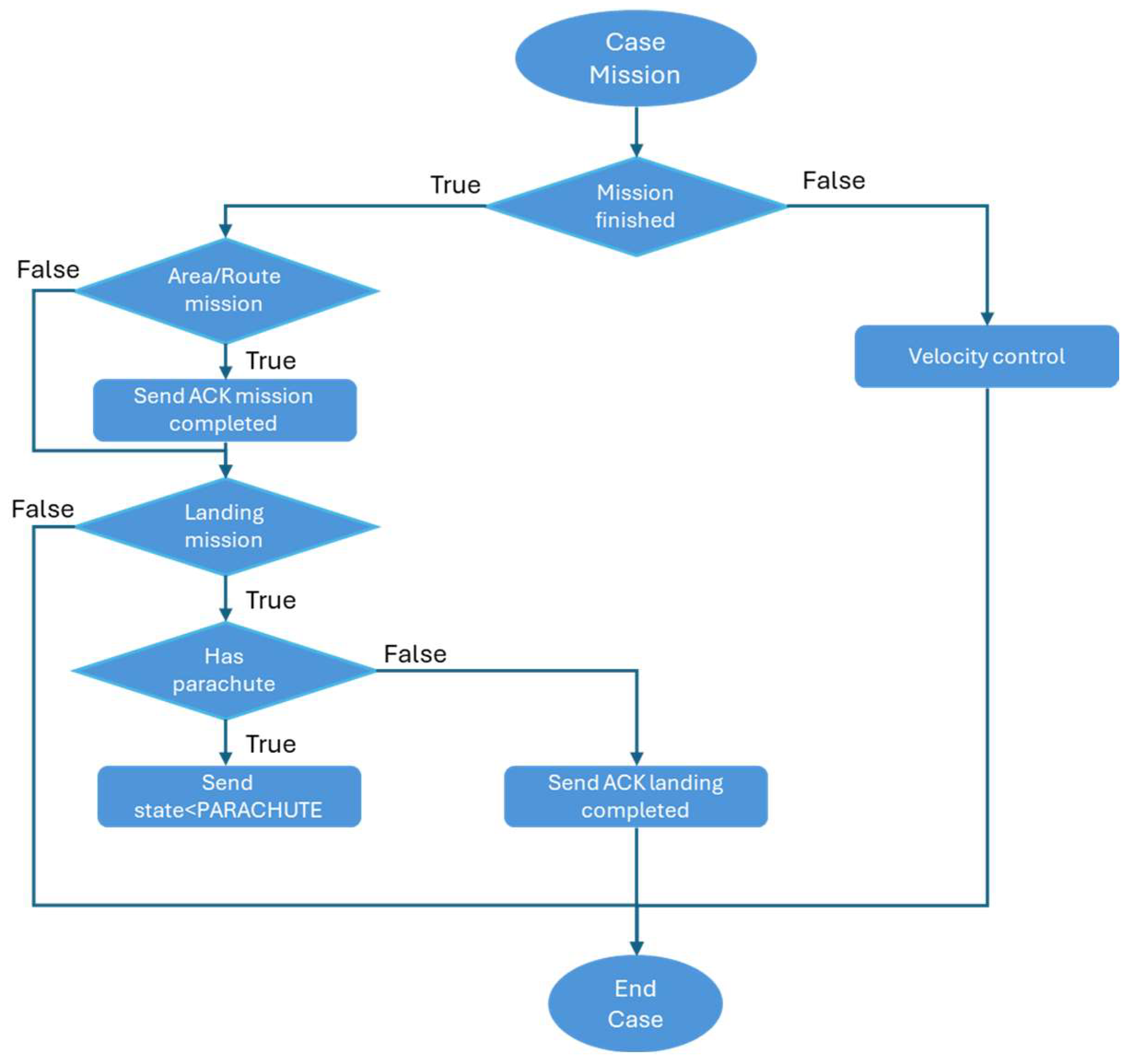
- MISSION_STATE_MISSION: Sends the calculated mission in the planning state and performs airspeed control until the mission is finished.
- MISSION_STATE_PARACHUTE: When the vehicle is equipped with a parachute, this protocol is activated to initiate the opening process.
- MISSION_STATE_SENDING_MISSION: This state specifically impacts missions of the swap type. The revised plan for the mission is transmitted to a different fleet.
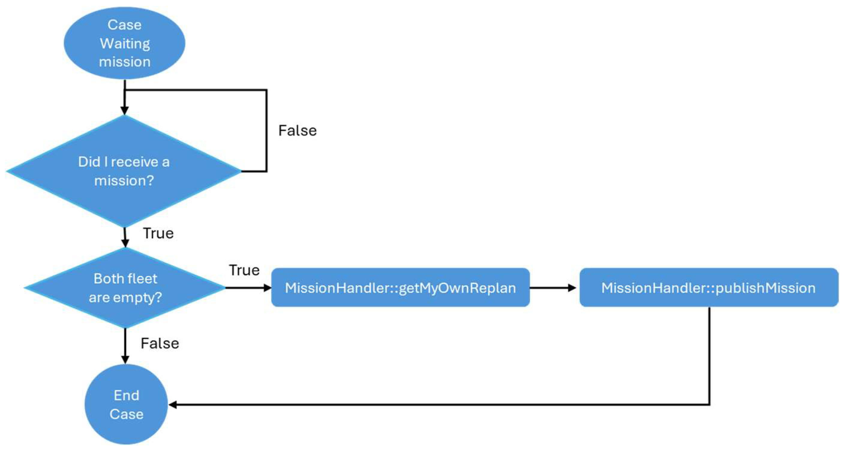
- MISSION_STATE_WAITING_MISSION: This state specifically impacts missions involving the swapping of items. The assignment is patiently awaited.
2.3.6. Planning State
- (a)
- Voting state
- (b)
- Pre-mission state
- (c)
- Mission state
- (d)
- Replan state
- (e)
- Sending mission state
- (f)
- Waiting mission state
- (g)
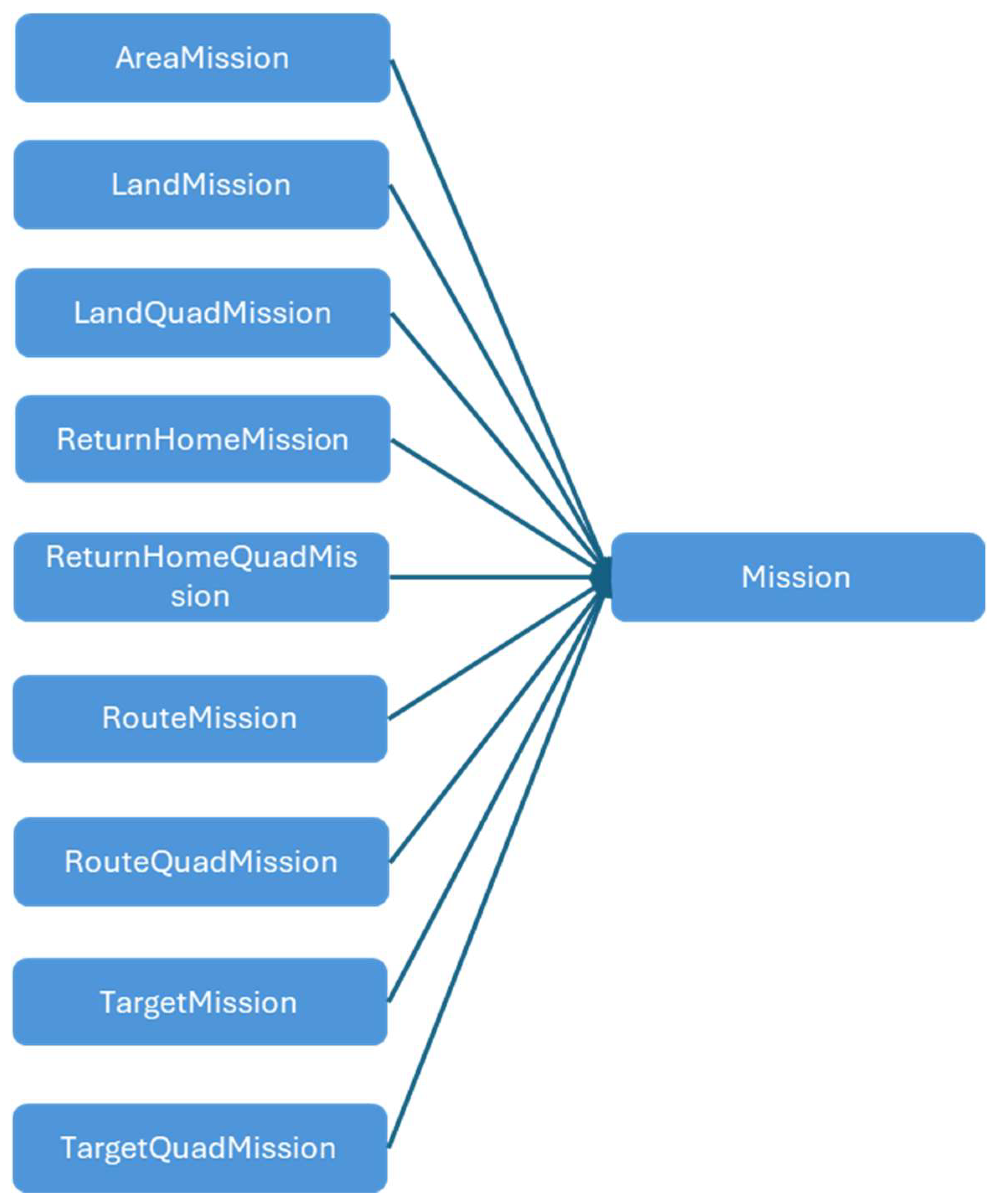
- Mission class
- ○
- Area: Supervise a region using many Unmanned Aerial Vehicles (UAVs) in a synchronized fashion.
- ○
- Target: Supervise the trajectory of several Unmanned Aerial Vehicles (UAVs) in a synchronized way.
- ○
- Perimeter surveillance: Aims to maximize the duration of overflight at each point.
- ○
- Objective: Monitoring a certain location using Unmanned Aerial Vehicles (UAVs) that are evenly distributed.
- ○
- Autoland: Swarm Airport Operations
- ○
- Manned–Unmanned Teaming: Refers to the collaboration and coordination between autonomous or remotely controlled systems. An explanation for this will be provided in a dedicated section as it forms a fundamental aspect of the system.
- ○
- Add: Integrate an Unmanned Aerial Vehicle (UAV) into a fleet of missions.
- ○
- Swap: Transfer materials across mission fleets.
- ○
- Collision avoidance: The purpose of the collision avoidance module is to proactively respond to potential collisions with other vehicles in the swarm or when they are at a distance that poses a risk. To prevent collisions, the primary responsive measure is to adjust the altitude, minimizing the need for significant alterations to the flight paths.
- ○
- Deliberative module: Perform decision-making using deterministic metrics, such as distance and battery level. The cars that achieve the greatest score will be the ones that perform the assignment.
- Vehicle quantity: The quantity of vehicles designated to exit the fleet.
- Payload model: The payload model required to execute the mission. By default, this is set to “none”. This parameter will be populated by the ground operator or automatically as necessary.
- Payload (p): This denotes the category of payload affixed to the vehicle. The weight is 0.6, and the score is computed as follows:
- ○
- If the installed payload type corresponds with the model mandated by the mission, it receives a score of 0.
- ○
- If it corresponds to the payload subtype mandated by the mission, it receives a score of 0.5.
- ○
- If it corresponds to the payload type necessary for the mission, it receives a score of 0.75.
- ○
- If there is no match, it receives a score of 1, denoting the lowest possible score.
- Time (t): This denotes the projected time required for the vehicle to arrive at the mission. The weight is 0.2, and the score is computed as follows:
- ○
- Initially, the reference point is assessed. This aspect will be contingent upon the nature of the mission:
- ○
- For MUM-T missions (terrestrial or aerial), the reference point will be the primary vehicle to which additional units will be appended.
- ○
- For missions using area or perimeter, the reference point will be the centroid of the polygon.
- ○
- For additional missions, the reference point will be the initiation point of each mission.
- ○
- The present distance from the vehicle to the reference location is computed and divided by its cruising velocity. Upon determining the predicted arrival time, the score is computed as atanh (time × 0.01).
- Battery (b): This denotes the residual battery percentage in the car. The weight is 0.3, and the score adheres to a linear equation in which 0 signifies 100% battery and 1 signifies 0% battery.
- The Collision Avoidance Module implements a fully decentralized conflict resolution strategy based on kinematic extrapolation of UAV trajectories. Each agent computes time-to-collision (TTC) against nearby UAVs using relative velocities and applies an upward-only altitude maneuver when separation thresholds are violated. Conflicts are resolved deterministically using a prioritization rule based on current altitude and UAV ID, with built-in hysteresis and safety constraints that prevent oscillations and ensure altitude restoration after conflict clearance.
- The Area Mission Planner decomposes arbitrary polygonal regions into a set of sweep lanes using a rotation-optimized boustrophedon strategy. Each UAV is assigned specific lanes based on its altitude, field-of-view, and the required image overlap, enabling cooperative, non-redundant coverage. Replanning support is built-in, allowing dynamic reassignment of subregions in case of UAV failure or reallocation.
- The Target Planner coordinates the spatial distribution of UAVs around a designated point, creating symmetric or asymmetric formations adapted to both rotary-wing (hover-capable) and fixed-wing (fly-through) platforms. The planner supports 3D structuring through configurable altitude steps and angle spacing, and can integrate the initial UAV positions to optimize arrival vectors. It is particularly well-suited to surveillance, loitering, or synchronized engagement scenarios.
- The Perimeter Mission Planner generates cyclic patrol paths along closed polygons or circular boundaries, assigning phase-offset starting points to each UAV. Fixed-wing aircraft receive smoothed paths respecting minimum turn radii, while multirotors benefit from tighter maneuvering and responsive yaw adjustments. The planner ensures loop continuity, handles UAV insertion/removal, and maintains consistent spacing through time- or angle-based offsets.
- The No-Fly Zone (NFZ) Manager provides dynamic geofence handling by detecting intersections between mission routes and evolving airspace restrictions. Upon detecting a violation, it attempts either vertical avoidance (via altitude change) or lateral rerouting (via path extension and polygonal inflation). When no safe path exists within UAV performance constraints, the system triggers a full mission replan and ensures swarm-wide consistency.
3. Ground Control Station
3.1. System Description
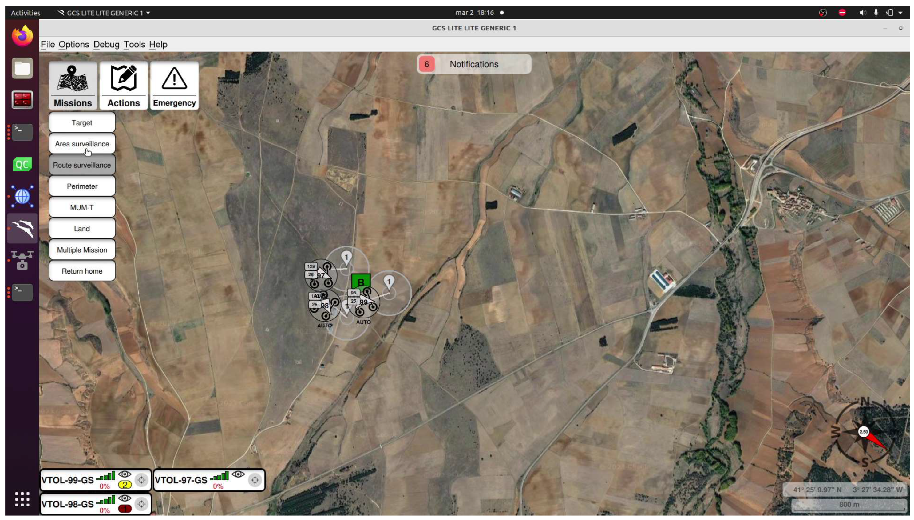
- Monitoring the states of the different vehicles;
- Interacting with the vehicles by sending different missions or actions.
3.2. System Architecture
- The DBHandler module is responsible for retrieving the required information from the database to be used in other modules.
- The DataManager module stores the information of various swarm systems and comprises three submodules:
- ○
- MultiVehicleManager contains the data related to the various vehicles in the system.
- ○
- The MissionManager is tasked with storing the data pertaining to all ongoing missions at any given moment.
- ○
- The PayloadsManager is tasked with managing the various payment loads within the system. The payment charges will transmit the information to the Payload Control Station, which will thereafter relay specific information to the Ground Control Station using a ROS link.
- CommsManager is tasked with initializing the ROS node to accept information from the various systems in the swarm.
- CommandManager is tasked with the creation and management of various messages that are intended to be sent to vehicles, primarily missions or commands.
- The ToolboxManager is tasked with integrating utility modules into the program.
- The InfoRecoveryManager module is responsible for saving the current status of the system’s nodes upon request, as well as loading various missions from a file. This is done in preparation for sending the swarm.
3.3. Communication
3.4. Mission Command
3.5. System Operation
3.5.1. Interface Description
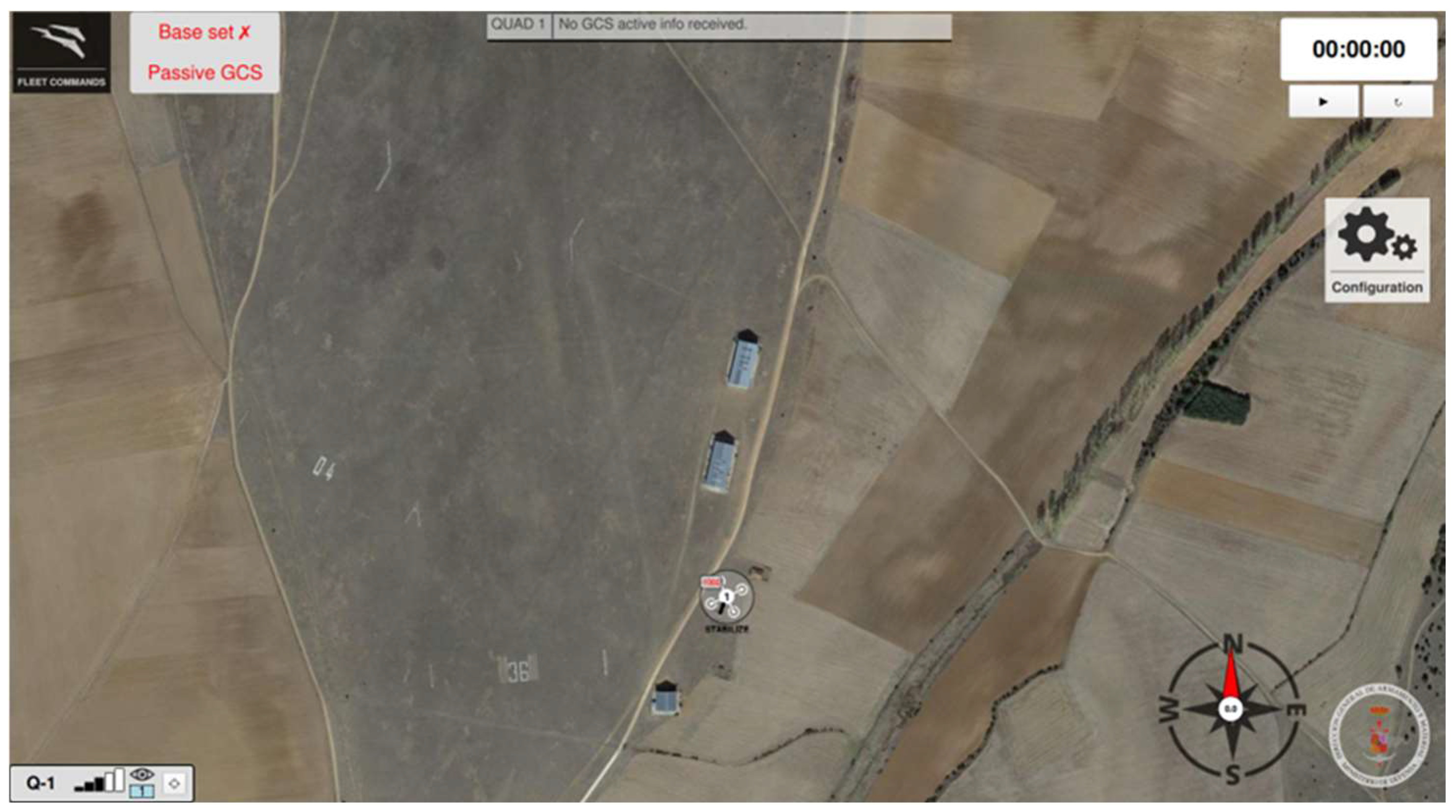
- Fleet Commands: Toggles the visibility of the command menu on the right-hand side.
- Emergency Landing: Commences the emergency landing procedure if the landing route has been specified; otherwise, it requests the entry of the route.
- Abort Landing: Implements the previously described “Cancel Landing” instruction.
- Parachute All: Engages the parachutes on all systems equipped with such devices.
- Incorporate into mission;
- Exchange missions;
- Adjust calibration;
- Dispatch more orders.
3.5.2. Vehicle Selection
- Select UAV: Enables the selection of each vehicle by sequentially clicking on the icons displayed on the map.
- Select Fleet: Selects all vehicles within the same fleet by clicking on the icon of any one vehicle.
- Select By ID: A menu will provide a list of all vehicles, enabling you to select your desired vehicle.
- Select All: Identifies all vehicles currently eligible.
3.5.3. Vehicle Information
- Vehicle designation;
- Packets received in the preceding second;
- Visibility status: Clicking the eye icon allows the user to conceal or reveal the vehicle icon on the map;
- Button to focus the map on the chosen vehicle;
- Fleet color border.
- Heading, pitch, and roll of the vehicle.
- The left column denotes the speed over the ground (Ground Speed) and speed in relation to the wind (Airspeed).
- The right column denotes the elevation above the ground.
- The vehicle’s name and base information are provided below the speeds.
- The remaining battery and GPS status are displayed below the height.
- The various sensors are displayed to the left of the battery, indicating whether the calibration has been successful.
- The Trajectory button toggles the visibility of the vehicle’s trajectory on the map within a temporary window.
4. Experiments and Simulation
- Collision Avoidance: Safeguarding UAV operations through the detection and prevention of probable collisions. Algorithms utilized altitude modifications and route reconfigurations to ensure safety, especially for fixed-wing UAVs that do not possess hovering skills.
- Autonomous Decision-Making: UAVs assigned mission-specific responsibilities (e.g., which unit should engage a certain target) depending on criteria such as proximity, energy levels, payload capacity, and mission priority.
- Advanced Planning Modules:
- ○
- Area Planner: Allocates exploration zones among UAVs for optimal coverage.
- ○
- Route Planner: Engineers optimum pathways to reduce energy expenditure and duration.
- ○
- Objective Planner: Assigns UAVs to one or several high-priority objectives.
- ○
- Perimeter Planner: Orchestrates UAVs to carry out surveillance and safeguard Ok, revised designated perimeters.
- ○
- Multi-Objective Planner: Coordinates UAVs to efficiently manage numerous simultaneous objectives.
- Target Reallocation: Immediate and dynamic reassignment of mission targets among UAVs to accommodate changing environmental circumstances and mission priorities.
- Self-Diagnostics: UAVs evaluate their operational conditions, encompassing battery levels, sensor performance, and overall mission preparedness. Diagnostic data is disseminated to the swarm to improve decision-making.
Experimental Configuration
- Area surveillance;
- Perimeter coverage;
- Route following with obstacle zones.
- Scenario: A comprehensive monitoring operation segmented into various zones using different mission planners.
- Objectives:
- ○
- Assess collision avoidance and spatial planning functionalities in a homogeneous fixed-wing UAV swarm.
- Execution:
- ○
- UAVs will execute four distinct missions: targeting, area coverage, perimeter surveillance, and route navigation, incorporating various autonomous replanning and re-tasking capabilities.
- ○
- The dynamic reassignment of missions guarantees comprehensive coverage while reducing overlaps.
- ○
- Collision avoidance systems regulate UAV proximity within restricted airspace.
- Parameters:Swarm Composition:
- Six fixed-wing Albatross 250 VTOL UAVs simulated in a ROS/Gazebo environment.
- Aircraft modeled on a reference platform with the following characteristics:
- ○
- Wingspan: 2500 mm
- ○
- Length: 1260 mm
- ○
- Cruise speed: 26 m/s @ 12.5 kg
- ○
- Stall speed: 15.5 m/s @ 12.5 kg
- ○
- Maximum flight altitude: 4800 m
- ○
- Wind resistance:
- ▪
- Fixed-wing mode: 10.8–13.8 m/s
- ▪
- VTOL mode: 5.5–7.9 m/s
- ○
- Payload:
- ▪
- Two-axis gyrostabilized 1.5Mpx camera
- ▪
- Gyrostabilization in roll and pith
Simulation Platform:- Executed on a Lenovo Legion 5 16IRX8 laptop:
- ○
- Intel Core i7-13700HX
- ○
- 32 GB DDR5 RAM
- ○
- NVIDIA GeForce RTX 4070 (8 GB)
- Real-time, high-fidelity simulation of multi-agent aerial swarm scenarios.
Architecture Emulation:- Ground Control Station (GCS) and Platform Control System (PCS) implemented as independent ROS nodes.
- Communication performed over a simulated mesh network with the following:
- ○
- Variable latency;
- ○
- Emulated packet loss;
- ○
- Signal degradation.
- Designed to mimic realistic communication environments.
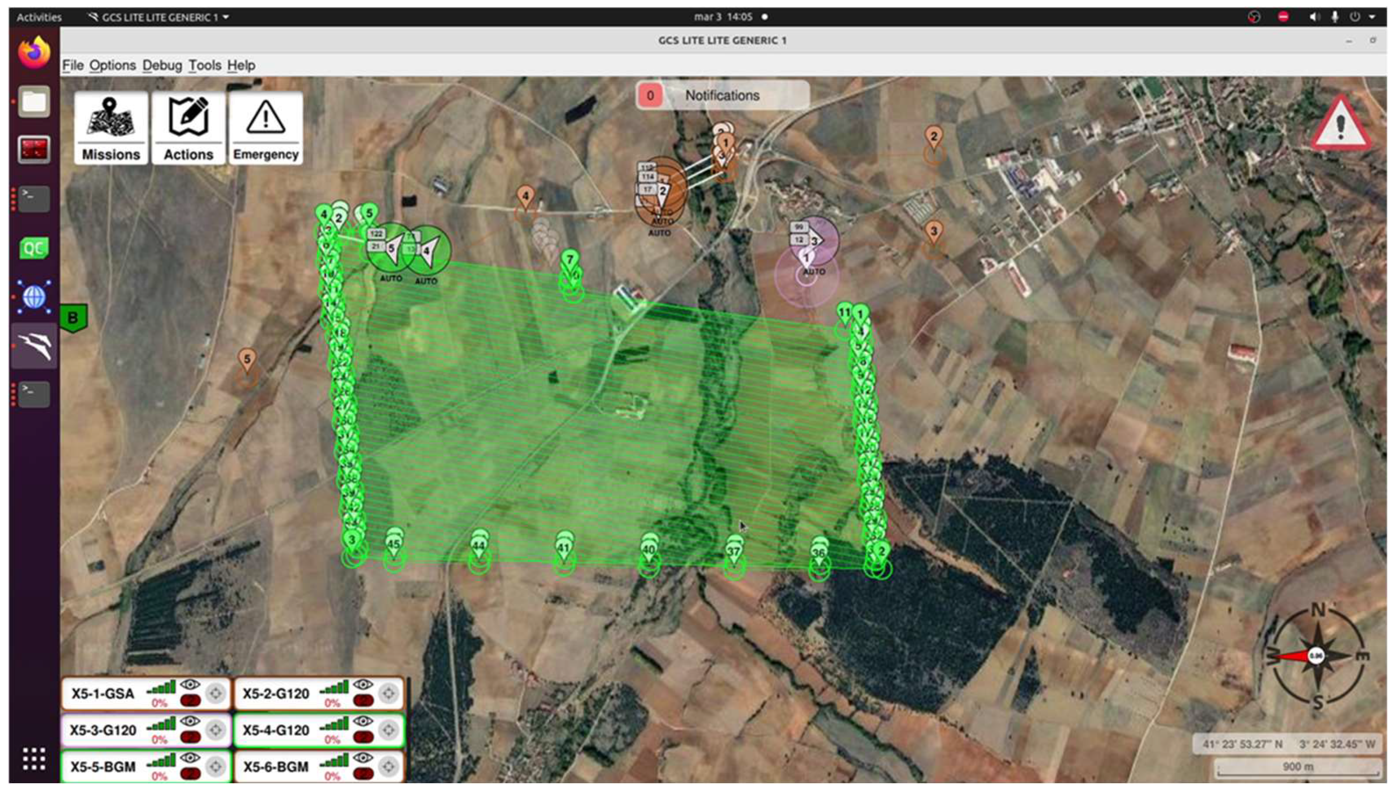
- 1.
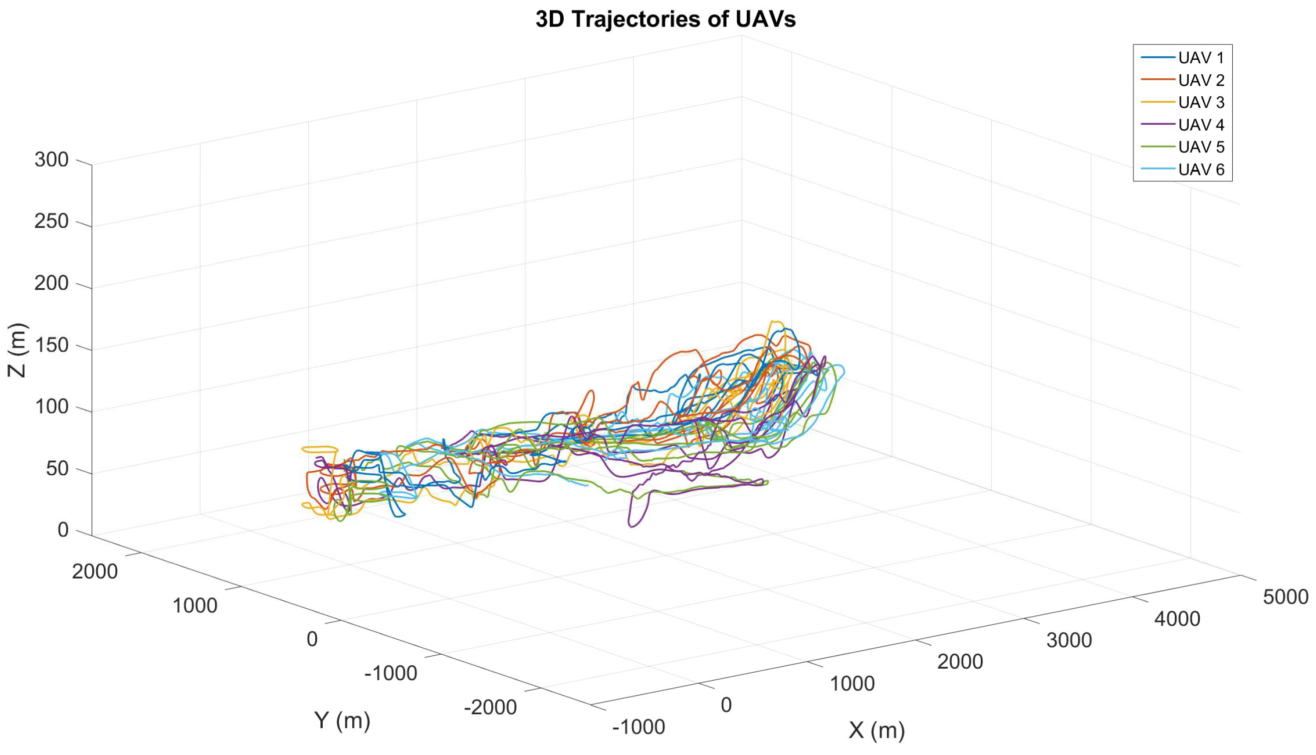
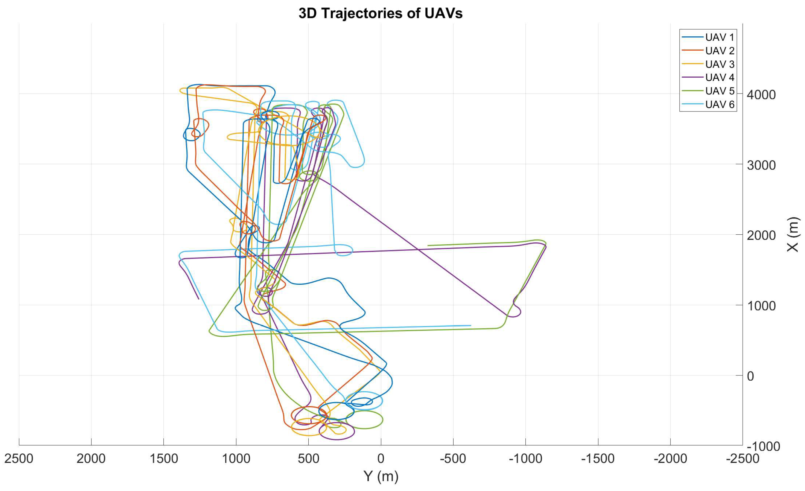
- Execution of an area with multiple UAVs: In the first phase, the initial planning and mission execution are shown using six UAVs. Here, the unmanned aerial vehicles work together to cover a designated area, shown in Figure 33, fulfilling exploration or surveillance objectives.
- 2.
- Replanning after detecting a target: Once a relevant target is identified, the system automatically performs dynamic replanning, as shown in Figure 34, assigning the necessary UAVs to investigate or engage with the target. This demonstrates the swarm’s ability to adapt in real time to unforeseen events.
- 3.
- Replanning to maintain area coverage: Finally, in Figure 35, the remaining UAVs that were not assigned to the target are strategically redistributed to continue covering the remaining area efficiently, ensuring the planned surveillance or exploration is maintained.
- Results:
- ○
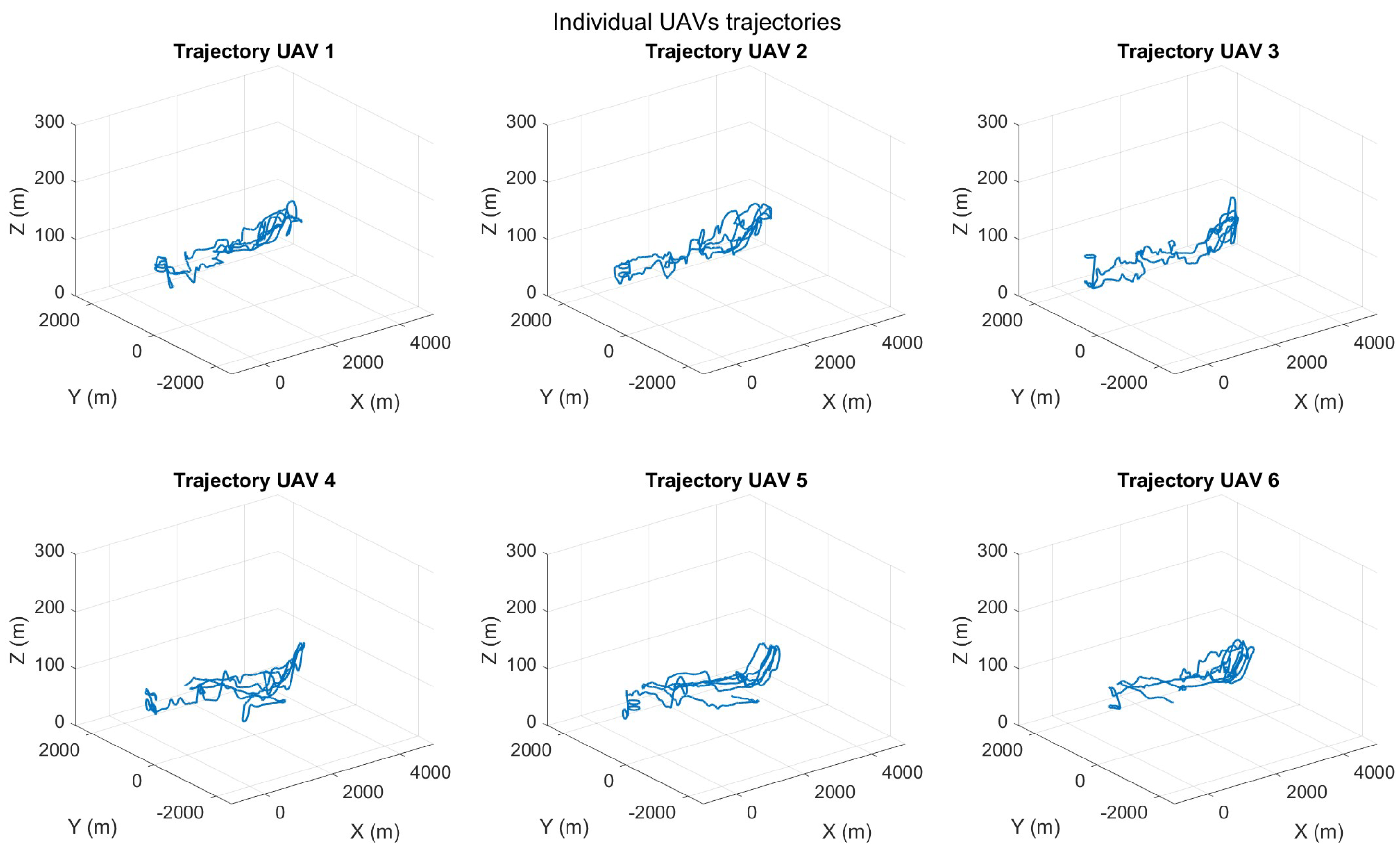
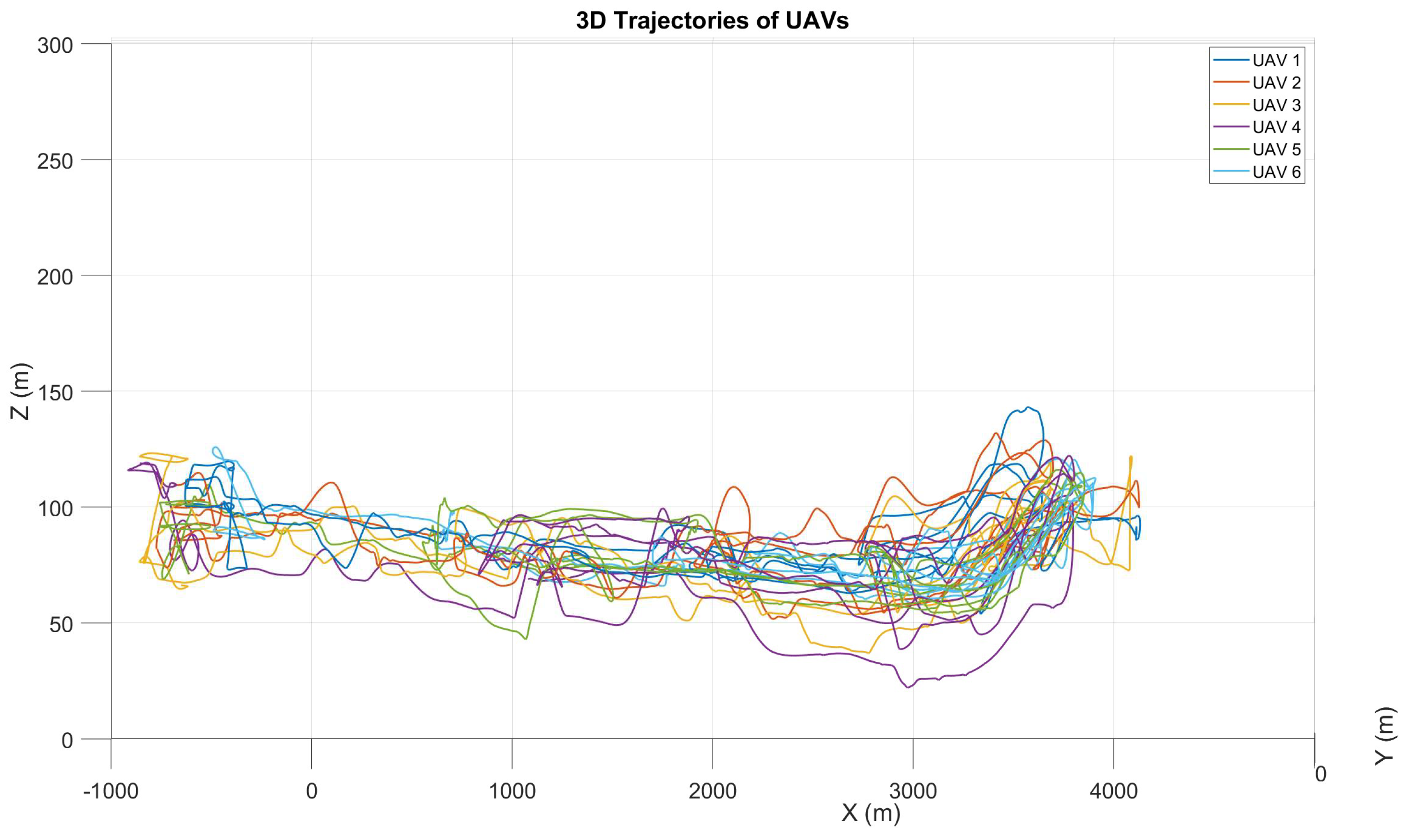
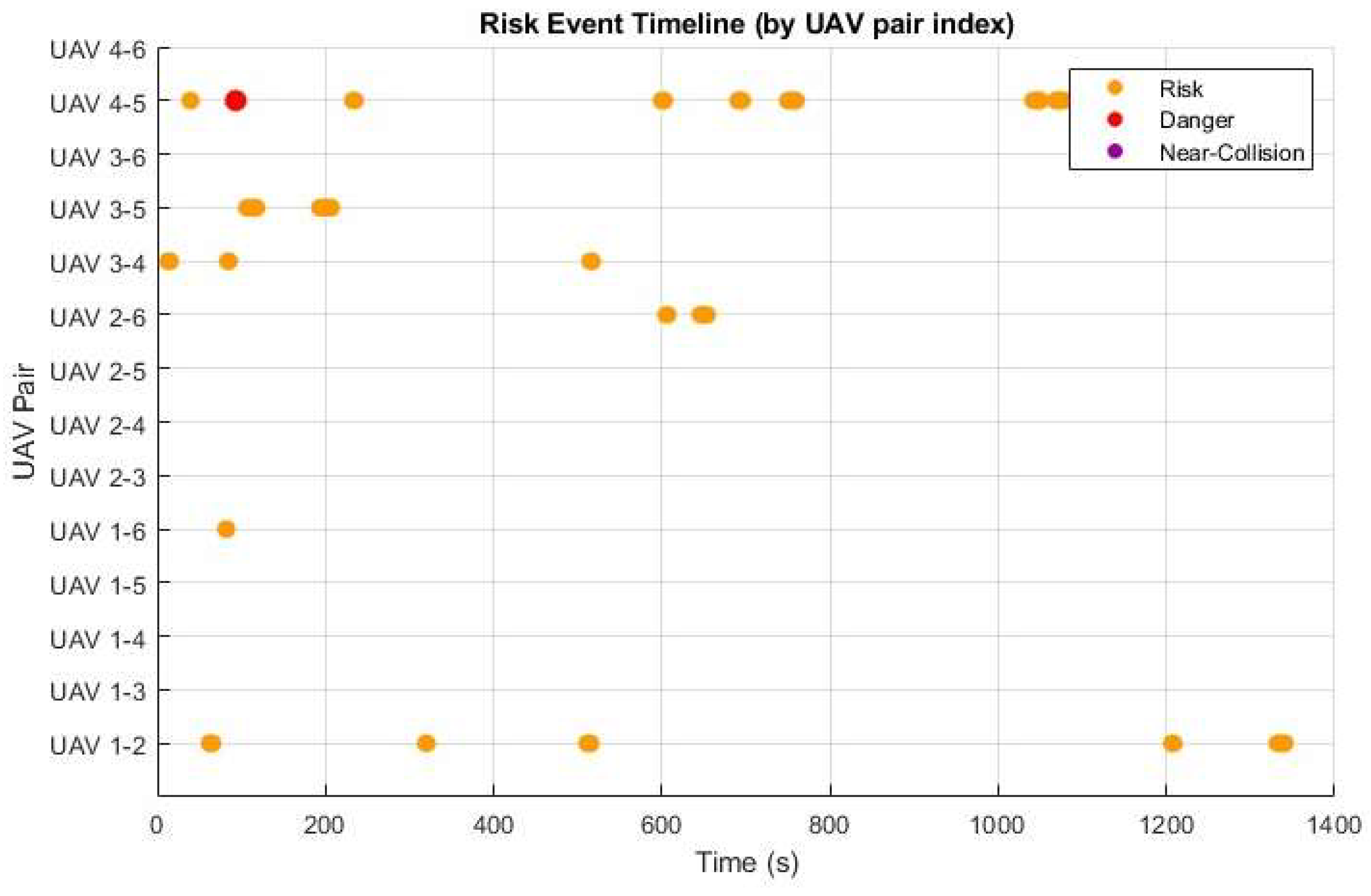
- Collision avoidance attained a 100% success rate, without any collision during the test.
- ○
- Autonomous decision-making inside the swarm reduced the operator’s workload, allowing the human-operated aircraft to focus on overarching mission objectives.
- ○
- The UAV swarm achieved a high accuracy rate in task execution, efficiently handling both exploration and target engagement.
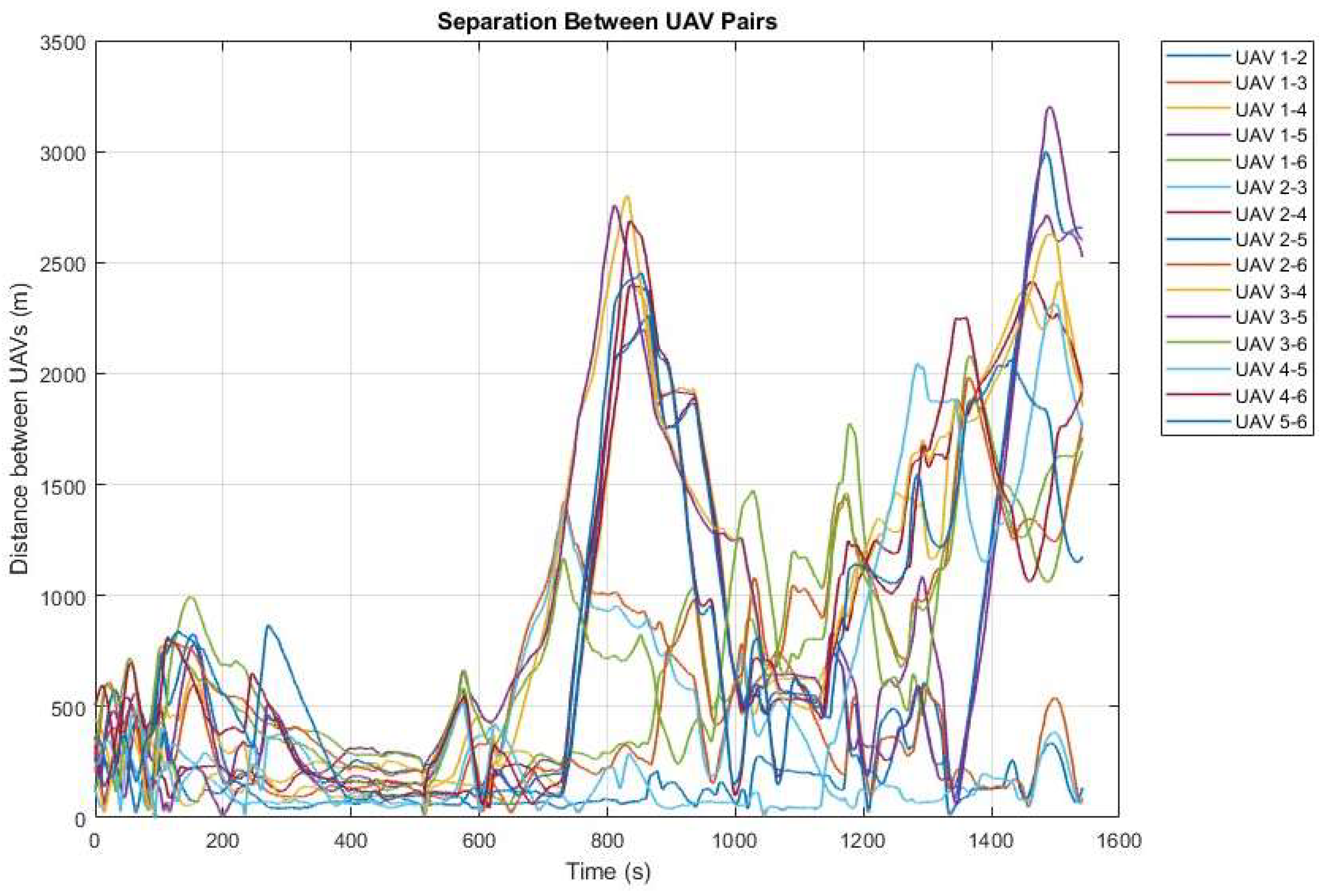
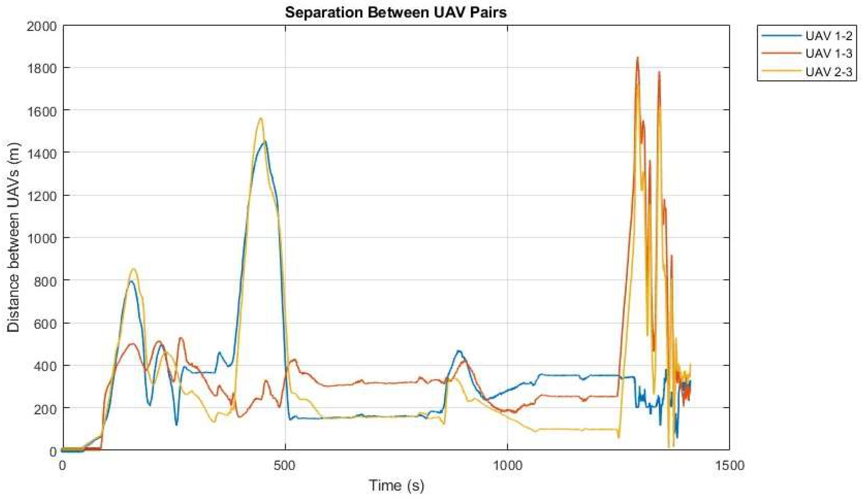
- Risk: distance between 10 and 40 m;
- Danger: distance between 5 and 10 m;
- Near-collision: distance below 5 m.
- Scenario:
- ○
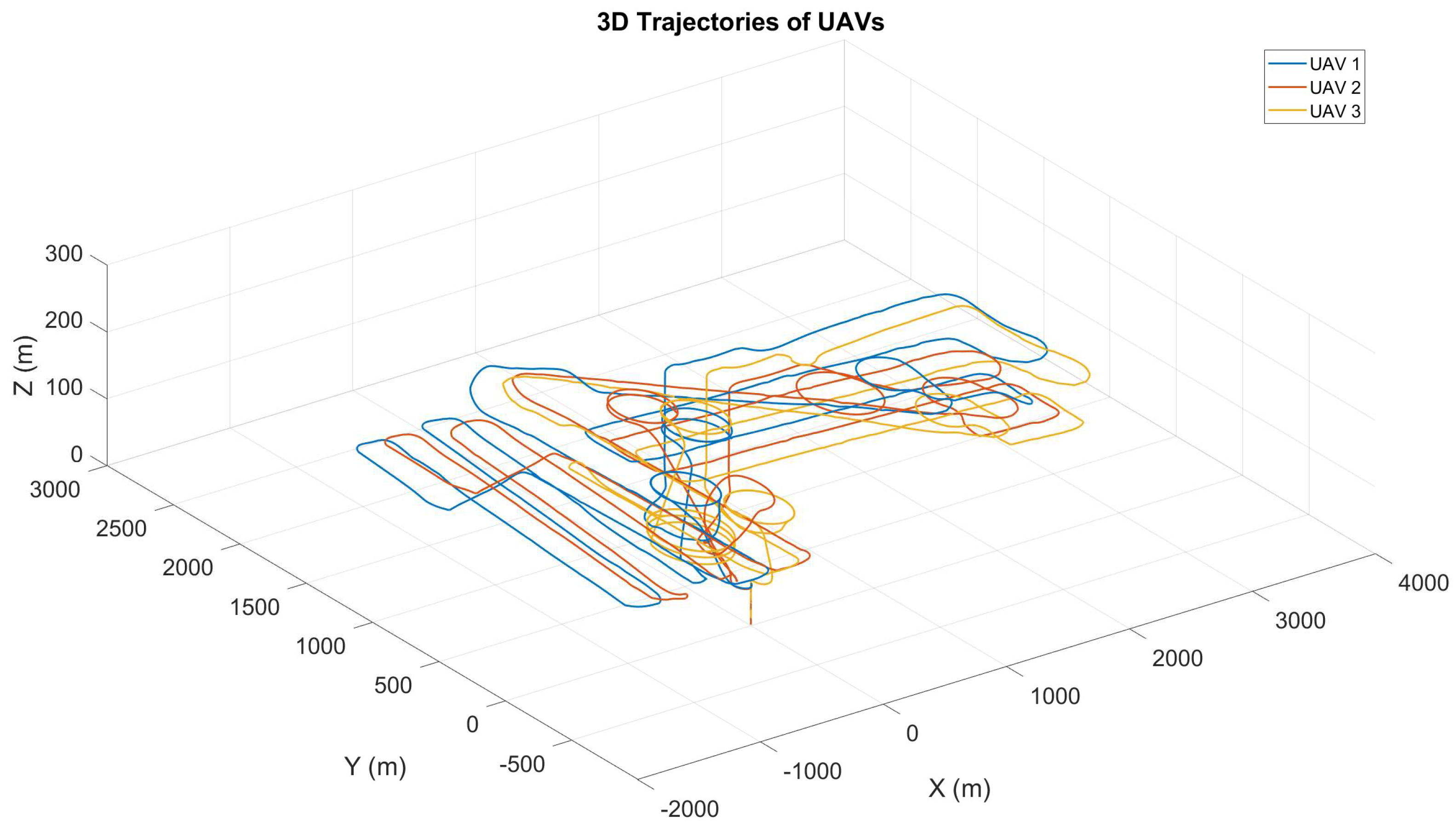
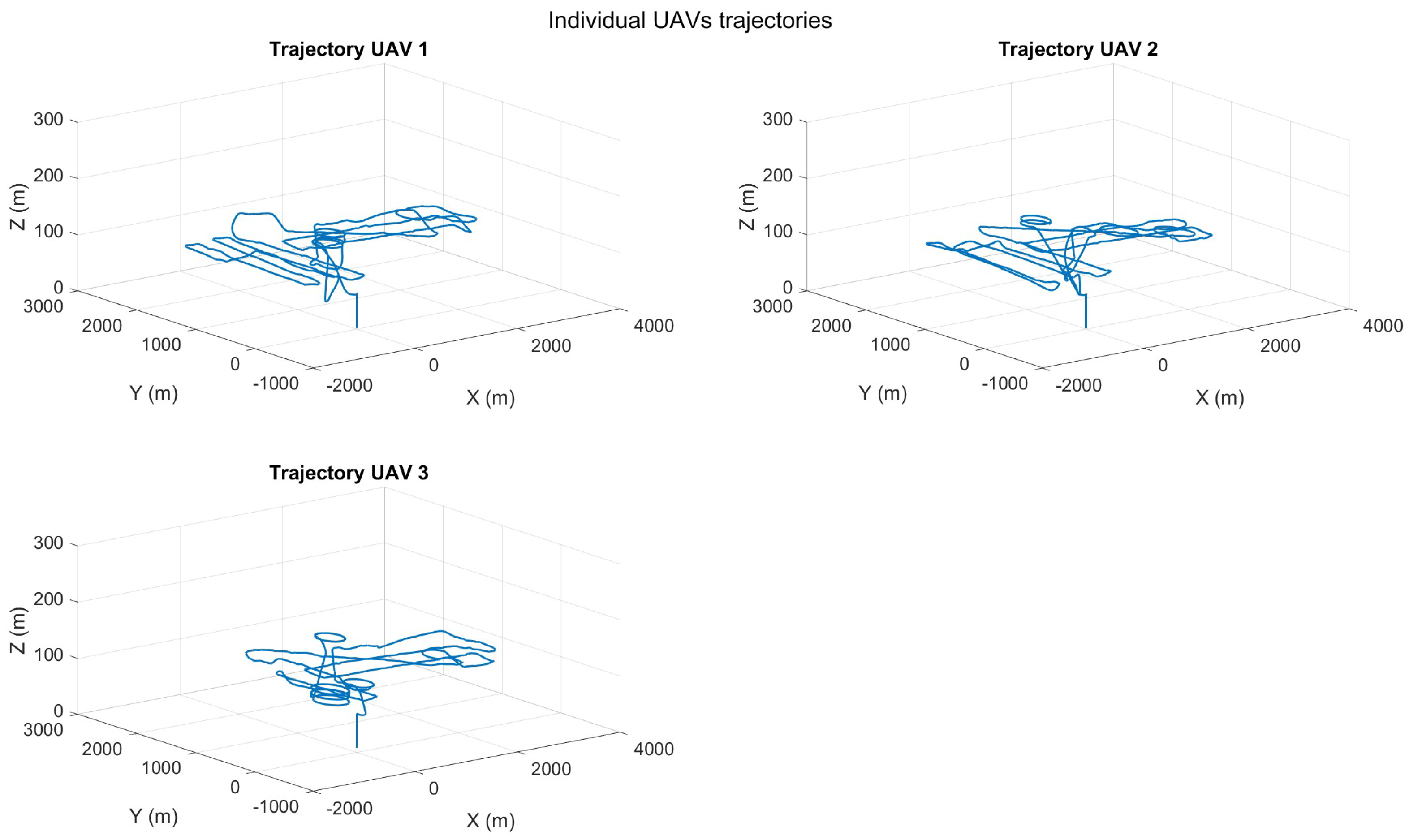
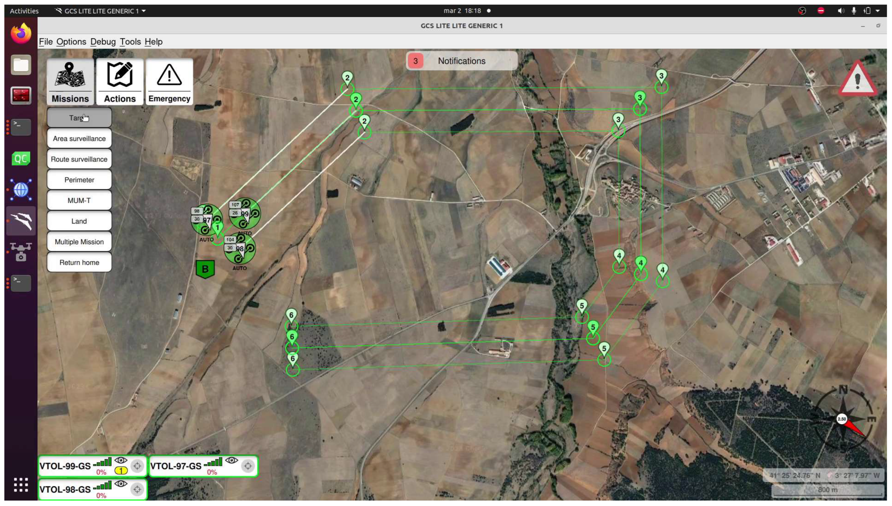
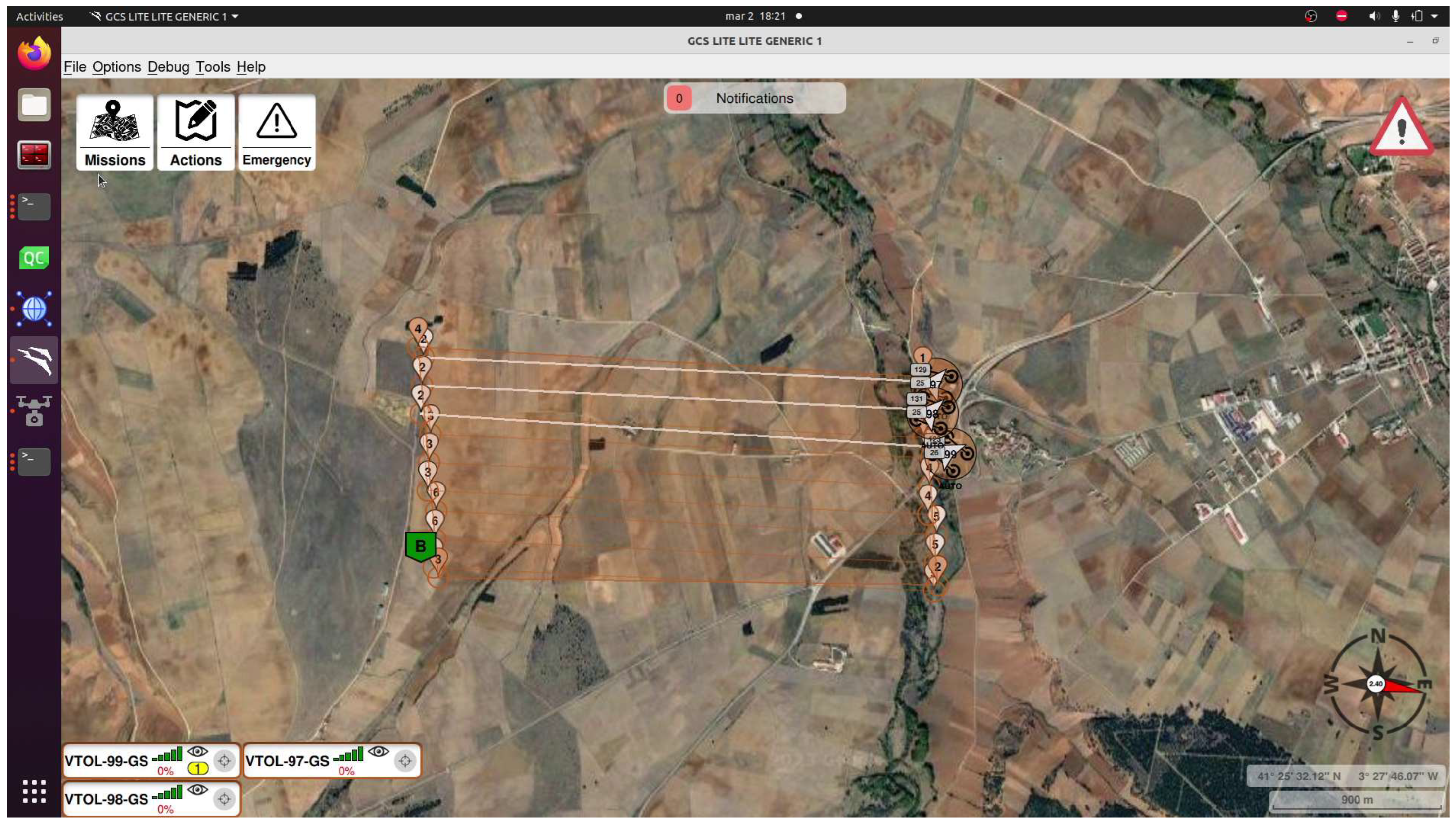
- Three VTOL UAVs performing different surveillance missions.
- Objectives:
- ○
- Assess collision avoidance and spatial planning functionalities in a homogeneous fixed-wing UAV swarm.
- ○
- Evaluate the swarm’s capacity to respond to directives from the Ground Control Station and Payload Control Station while preserving autonomous decision-making for subordinate tasks.
- Execution:
- ○
- UAVs will execute four distinct missions: targeting, area coverage, perimeter surveillance, and route navigation, incorporating various autonomous replanning and re-tasking capabilities.
- ○
- The dynamic reassignment of missions guarantees comprehensive coverage while reducing overlaps.
- ○
- Collision avoidance systems regulate UAV proximity within restricted airspace.
- Parameters:Swarm Composition:
- Three fixed-wing Albatross 250 VTOL UAVs:
- ○
- Wingspan: 2500 mm
- ○
- Length: 1260 mm
- ○
- Material: Carbon fiber
- ○
- Empty weight (no battery): 7.0 kg
- ○
- Maximum take-off weight: 15.0 kg (Experiment MTOW used)
- ○
- Cruise speed: 26 m/s @ 12.5 kg
- ○
- Stall speed: 15.5 m/s @ 12.5 kg
- ○
- Maximum flight altitude: 4800 m
- ○
- Wind resistance:
- ▪
- Fixed-wing mode: 10.8–13.8 m/s
- ▪
- VTOL mode: 5.5–7.9 m/s
- ○
- Operating voltage: 12 S
- ○
- Temperature range: –20 °C to 45 °C
GCS:- Executed on a Lenovo Legion 5 16IRX8 laptop:
- ○
- Intel Core i7-13700HX
- ○
- 32 GB DDR5 RAM
- ○
- NVIDIA GeForce RTX 4070 (8 GB)
- Communications:
- ○
- XTEND 900 mhz 1 W for mesh communications
- ▪
- Antenna omni 5 Dbi for airplane
- ▪
- Antenna omni 11 Dbi for ground
- Results:
- ○
- Autonomous decision-making within the swarm diminished the operator’s workload, enabling the human-operated aircraft to concentrate on high-level mission goals.
- ○
- The UAV swarm attained a high accuracy rate in job fulfilment, effectively managing both exploration and target engagement.
Key Findings and Principal Conclusions
- 1.
- Collision Avoidance:
- Fixed-wing UAVs effectively adjusted altitudes to prevent collisions.
- Multirotors demonstrated precise avoidance with dynamic hovering and shifting.
- 2.
- Decision-Making and Target Reallocation:
- Algorithms reduced operator workload by enabling task reassignment based on proximity, capabilities, and readiness.
- Improved mission continuity during unforeseen events, such as UAV failures.
- 3.
- Advanced Planning Capabilities:
- Area and multi-objective planners optimized task distribution and minimized redundancy.
- Transitioned seamlessly between mission, tasks, and re-tasking.
- 4.
- Energy and Resource Management:
- Energy-efficient strategies prioritized tasks based on battery levels.
- Reduced idle times enhanced overall swarm productivity.
5. Conclusions
- Sophisticated mission planners for area surveillance, perimeter security, and multi-objective tasks.
- Collision avoidance algorithms that ensured a 100% success rate in preventing UAV collisions, even in dense airspace.
- Real-time decision-making for dynamic mission reallocation, reducing operator workload and optimizing task execution.
- 1.
- Scalability:
- Extending the swarm to manage a larger number of UAVs while maintaining efficiency and coordination.
- 2.
- Advanced Communication Protocols:
- Developing robust protocols to improve resilience in contested or challenging environments.
- 3.
- Machine Learning Integration:
- Implementing predictive analytics and dynamic mission planning using machine learning models to enhance decision-making.
- 4.
- Enhanced Manned–Unmanned Collaboration:
- Refining collaboration techniques to broaden utility across diverse mission scenarios, including military and civilian operations.
Supplementary Materials
Author Contributions
Funding
Data Availability Statement
Conflicts of Interest
References
- Sahin, E. Swarm Robotics: From Sources of Inspiration to Domains of Application. In International Workshop on Swarm Robotics; EEE/RSJ International; Springer: Berlin/Heidelberg, Germany, 2005. [Google Scholar]
- Parunak, H.V. Making Swarming Happen. In Proceedings of the Conference on Swarming and C4ISR, Tysons Corner, VA, USA, 3 January 2003. [Google Scholar]
- Cao, Y.U.; Fukunaga, A.S.; Kahng, A.B.; Meng, F. Cooperative Mobile Robotics: Antecedents and Directions. In Proceedings of the 1995 IEEE/RSJ International Conference on Intelligent Robots and Systems, Human Robot Interaction and Cooperative Robots, Pittsburgh, PA, USA, 5–9 August 1995; Volume 1, pp. 226–234. [Google Scholar] [CrossRef]
- Beni, G. Swarm Intelligence in Cellular Robotic Systems. In Robots and Biological Systems: Towards a New Bionics; NATO ASI Series; Springer: Berlin/Heidelberg, Germany, 1993; Volume 102, pp. 703–712. [Google Scholar]
- Beni, G. From Swarm Intelligence to Swarm Robotics. In Swarm Robotics; Lecture Notes in Computer Science; Springer: Berlin/Heidelberg, Germany, 2005; Volume 3342. [Google Scholar]
- Dekker, A. A Taxonomy of Network Centric Warfare Architectures. Syst. Eng./Test Eval. 2007, 3, 103–104. [Google Scholar]
- Chung, T.K. 50 vs. 50 by 2015: Swarm vs. Swarm UAV Live-Fly Competition at the Naval Postgraduate School. In Proceedings of the AUSVI, Atlanta, GA, USA, 4–7 May 2015. [Google Scholar]
- Frew, E. Airborne Communication Networks for Small Unmanned Aircraft. Proc. IEEE 2008, 96, 2008–2027. [Google Scholar] [CrossRef]
- Weiskopf, F.T. Control of Cooperative, Autonomous Unmanned Aerial Vehicles. In Proceedings of the First AIAA Technical Conference and Workshop on UAV, Portsmouth, VA, USA, 20–22 May 2002. [Google Scholar]
- Sánchez-López, J.L.; Molina, M.; Bavle, H.; Sampedro, C.; Suárez-Fernández, R.A.; Campoy, P. A Multi-Layered Component-Based Approach for the Development of Aerial Robotic Systems: The Aerostack Framework. J. Intell. Robot. Syst. 2017, 88, 686–709. [Google Scholar] [CrossRef]
- Fernández-Cortizas, M.; Molina, M.; Arias-Pérez, P.; Pérez-Segui, R.; Pérez-Saura, D.; Campoy, P. Aerostack2: A software framework for developing multi-robot aerial system. arXiv 2023, arXiv:2303.18237. [Google Scholar] [CrossRef]
- Villemure, É.; Arsenault, P.; Lessard, G.; Constantin, T.; Dubé, H.; Gaulin, L.-D.; Groleau, X.; Laperrière, S.; Quesnel, C.; Ferland, F. SwarmUS: An open hardware and software on-board platform for swarm robotics development. arXiv 2022, arXiv:2203.02643. [Google Scholar]
- Starks, M.; Gupta, A.; Oruganti Venkata, S.S.; Parasuraman, R. HeRoSwarm: Fully-Capable Miniature Swarm Robot Hardware Design with Open-Source ROS Support. arXiv 2022, arXiv:2211.0301. [Google Scholar]
- Loi, A.; Macabre, L.; Fersula, J.; Amini, K.; Cazenille, L.; Caura, F.; Guerre, A.; Gourichon, S.; Dauchot, O.; Bredeche, N. Pobogot: An Open-Hardware Open-Source Low Cost Robot for Swarm Robotics. arXiv 2025, arXiv:2504.08686. [Google Scholar]
- Kedia, P.; Rao, M. GenGrid: A Generalised Distributed Experimental Environmental Grid for Swarm Robotics. arXiv 2025, arXiv:2504.20071. [Google Scholar]
- Community. UAVros: PX4 Multi-Rotor UAV and UGV Swarm Simulation Kit. ROS Discourse. 2024. Available online: https://discuss.px4.io/t/announcing-uavros-a-ros-kit-for-px4-multi-rotor-uav-and-ugv-swarm-simulation/42132 (accessed on 4 May 2025).
- Tastier, A. “PX4 Swarm Controller.” GitHub Repository. 2023. Available online: https://github.com/artastier/PX4_Swarm_Controller (accessed on 4 May 2025).
- Kaiser, T.K.; Begemann, M.J.; Plattenteich, T.; Schilling, L.; Schildbach, G.; Hamann, H. ROS2swarm: A ROS 2 Package for Swarm Robot Behaviors. In Proceedings of the IEEE International Conference on Robotics and Automation (ICRA), Philadelphia, PA, USA, 23–27 May 2022. [Google Scholar]
- Zimmermann, J.; Rinner, B.; Schindler, T. ROS2swarm: A Modular Swarm Behavior Framework for ROS 2. arXiv 2024, arXiv:2405.02438. [Google Scholar]
- Benavidez, P.; Jamshidi, M. Multi-domain robotic swarm communication system. In Proceedings of the IEEE International Systems Conference (SoSE), San Antonio, TX, USA, 16–18 April 2008. [Google Scholar]
- Nguyen, L. Swarm Intelligence-Based Multi-Robotics: A Comprehensive Review. AppliedMath 2024, 4, 1192–1210. [Google Scholar] [CrossRef]
- Guihen, D. The Barriers and Opportunities of Effective Underwater Autonomous Swarms. In Thinking Swarms; Springer: Berlin/Heidelberg, Germany, 2025. [Google Scholar]
- St-Onge, D.; Pomerleau, F.; Beltrame, G. OS and Buzz: Consensus-based behaviors for heterogeneous teams. arXiv 2017, arXiv:1710.08843. [Google Scholar]
- Sardinha, H.; Dragone, M.; Patricia, A. Closing the Gap in Swarm Robotics Simulations: An Extended Ardupilot/Gazebo Plugin. arXiv 2018, arXiv:1811.06948. [Google Scholar] [CrossRef]
- Adoni, W.; Fareedh, J.S.; Lorenz, S.; Gloaguen, R.; Madriz, Y.; Madriz, Y.; Madriz, Y. Intelligent Swarm: Concept, Design and Validation of Self-Organized UAVs Based on Leader–Followers Paradigm. Drones 2024, 8, 575. [Google Scholar] [CrossRef]
- Mao, P.; Lv, S.; Min, C.; Shen, Z.; Quan, Q. An Efficient Real-Time Planning Method for Swarm Robotics Based on an Optimal Virtual Tube. arXiv 2025, arXiv:2505.01380. [Google Scholar] [CrossRef]
- Darush, Z.; Martynov, M.; Fedoseev, A.; Shcherbak, A.; Tsetserukou, D. SwarmGear: Heterogeneous Swarm of Drones with Reconfigurable Leader Drone. arXiv 2023, arXiv:2304.02956. [Google Scholar] [CrossRef]
- Gupta, A.; Baza, A.; Dorzhieva, E.; Alper, M. SwarmHive: Heterogeneous Swarm of Drones for Robust Autonomous Landing on Moving Robot. arXiv 2022, arXiv:2206.08856. [Google Scholar] [CrossRef]





















| Framework | ROS Version | UAV/UGV Support | Distributed Control | Real Hardware Integration | Modularity | Payload Management Support |
|---|---|---|---|---|---|---|
| UAVros | ROS1/ROS2 | Yes | Partial | No | Medium | Not included |
| PX4 Swarm Controller | ROS2 | Yes | Yes | No | High | Not included |
| Aerostack2 | ROS2 | Yes | Yes | Yes | High | Basic (camera/GPS only) |
| ROS2swarm | ROS2 | Yes | Yes | Partial (Sim-only) | High | Not included |
| SwarmUS | Custom/ROS1 | Partial | Yes | Partial | Medium | No payload-level integration |
| HeRoSwarm | ROS1 | No (mini swarm) | Yes | Partial (lab-scale robots) | Medium | No |
| Pobogot | Custom | No (lab-scale) | Yes | No | Medium | No |
| This work | ROS1 | Yes | Yes | Yes | High | Yes (modular, advanced) |
| Pair | MinDistance_m | RiskEvents | DangerEvents | NearCollisionEvents |
|---|---|---|---|---|
| UAV 1–2 | 12.29 | 144 | 0 | 0 |
| UAV 1–3 | 49.30 | 0 | 0 | 0 |
| UAV 1–4 | 91.27 | 0 | 0 | 0 |
| UAV 1–5 | 89.48 | 0 | 0 | 0 |
| UAV 1–6 | 36.61 | 8 | 0 | 0 |
| UAV 2–3 | 42.43 | 0 | 0 | 0 |
| UAV 2–4 | 42.14 | 0 | 0 | 0 |
| UAV 2–5 | 67.39 | 0 | 0 | 0 |
| UAV 2–6 | 24.56 | 66 | 0 | 0 |
| UAV 3–4 | 13.86 | 54 | 0 | 0 |
| UAV 3–5 | 10.21 | 122 | 0 | 0 |
| UAV 3–6 | 119.50 | 0 | 0 | 0 |
| UAV 4–5 | 8.09 | 248 | 4 | 0 |
| UAV 4–6 | 56.44 | 0 | 0 | 0 |
| UAV 5–6 | 74.55 | 0 | 0 | 0 |
| Pair | MinDistance_m | RiskEvents | DangerEvents | NearCollisionEvents |
|---|---|---|---|---|
| UAV 1–2 | 2.04 | 94 | 14 | 210 |
| UAV 1–3 | 5.06 | 12 | 398 | 0 |
| UAV 2–3 | 5.10 | 123 | 204 | 0 |
Disclaimer/Publisher’s Note: The statements, opinions and data contained in all publications are solely those of the individual author(s) and contributor(s) and not of MDPI and/or the editor(s). MDPI and/or the editor(s) disclaim responsibility for any injury to people or property resulting from any ideas, methods, instructions or products referred to in the content. |
© 2025 by the authors. Licensee MDPI, Basel, Switzerland. This article is an open access article distributed under the terms and conditions of the Creative Commons Attribution (CC BY) license (https://creativecommons.org/licenses/by/4.0/).
Share and Cite
Martin, J.; Esteban, S. ROS-Based Multi-Domain Swarm Framework for Fast Prototyping. Aerospace 2025, 12, 702. https://doi.org/10.3390/aerospace12080702
Martin J, Esteban S. ROS-Based Multi-Domain Swarm Framework for Fast Prototyping. Aerospace. 2025; 12(8):702. https://doi.org/10.3390/aerospace12080702
Chicago/Turabian StyleMartin, Jesus, and Sergio Esteban. 2025. "ROS-Based Multi-Domain Swarm Framework for Fast Prototyping" Aerospace 12, no. 8: 702. https://doi.org/10.3390/aerospace12080702
APA StyleMartin, J., & Esteban, S. (2025). ROS-Based Multi-Domain Swarm Framework for Fast Prototyping. Aerospace, 12(8), 702. https://doi.org/10.3390/aerospace12080702


