Article

A Secure Satellite Transmission Technique via Directional Variable Polarization Modulation with MP-WFRFT

1
College of Electronic Science and Technology, National University of Defense Technology, Changsha 410073, China
2
National Key Laboratory for Positioning, Navigation and Timing Technology, Changsha 410073, China
*
Author to whom correspondence should be addressed.
Aerospace 2025, 12(8), 690; https://doi.org/10.3390/aerospace12080690 (registering DOI)
Submission received: 6 June 2025 / Revised: 18 July 2025 / Accepted: 25 July 2025 / Published: 31 July 2025
(This article belongs to the Section Astronautics & Space Science)

Abstract

Satellite communications are pivotal to global Internet access, connectivity, and the advancement of information warfare. Despite these importance, the open nature of satellite channels makes them vulnerable to eavesdropping, making the enhancement of interception resistance in satellite communications a critical issue in both academic and industrial circles. Within the realm of satellite communications, polarization modulation and quadrature techniques are essential for information transmission and interference suppression. To boost electromagnetic countermeasures in complex battlefield scenarios, this paper integrates multi-parameter weighted-type fractional Fourier transform (MP-WFRFT) with directional modulation (DM) algorithms, building upon polarization techniques. Initially, the operational mechanisms of the polarization-amplitude-phase modulation (PAPM), MP-WFRFT, and DM algorithms are elucidated. Secondly, it introduces a novel variable polarization-amplitude-phase modulation (VPAPM) scheme that integrates variable polarization with amplitude-phase modulation. Subsequently, leveraging the VPAPM modulation scheme, an exploration of the anti-interception capabilities of MP-WFRFT through parameter adjustment is presented. Rooted in an in-depth analysis of simulation data, the anti-scanning capabilities of MP-WFRFT are assessed in terms of scale vectors in the horizontal and vertical direction. Finally, exploiting the potential of the robust anti-scanning capabilities of MP-WFRFT and the directional property of antenna arrays in DM, the paper proposes a secure transmission technique employing directional variable polarization modulation with MP-WFRFT. The performance simulation analysis demonstrates that the integration of MP-WFRFT and DM significantly outperforms individual secure transmission methods, improving anti-interception performance by at least an order of magnitude at signal-to-noise ratios above 10 dB. Consequently, this approach exhibits considerable potential and engineering significance for its application within satellite communication systems.

1. Introduction

Satellite communication technology is pivotal across a spectrum of applications, including the establishment of integrated air, space, and submarine networks [1,2]; low-orbit communications [3]; satellite internet of things [4,5]; satellite navigation [6,7]; and advanced millimeter-wave satellite communications [8]. It particularly excels in the realms of information warfare and unmanned combat, demonstrating distinct advantages [9]. Despite these strengths, satellite communications encounter challenges such as scarce spectrum resources and stringent carrier synchronization accuracy demands during their evolution. Polarization, an additional dimension of electromagnetic waves beyond time, frequency, and spatial domains, offers a novel avenue for information transmission by utilizing the polarization state as an information carrier itself. However, the open nature and broad reach of satellite communication channels render the security of polarized information vulnerable to eavesdropping, underscoring the critical need to boost the anti-interception capabilities of satellite communications.
Anti-interception strategies for satellite communication systems can be broadly categorized into two primary approaches: conventional cryptographic methods and physical layer secure transmission techniques [10,11,12]. The former concentrates on the cryptographic manipulation of message content, leveraging the intricacy of algorithms and encryption keys to safeguard data confidentiality. In contrast, physical layer security techniques concentrate on manipulating the waveform, structure, and form of the transmitted signal, harnessing the inherent properties of the wireless channel to enhance communication security. Among these physical layer techniques, the multi-parameter weighted-type fractional Fourier transform (MP-WFRFT) has garnered significant interest due to its channel state information independence. Despite various definitions from different perspectives, fractional Fourier transforms (FRFT) are fundamentally and logically equivalent, hence collectively termed classical fractional Fourier transform (CFRFT) [13,14,15]. To mitigate the complexity of FRFT, weighted-type fractional Fourier transform (WFRFT) [16] has been proposed for digital communication systems, with in-depth studies on its applications in such systems [17,18,19]. Another key technique is directional modulation (DM), which involves the precise manipulation of signal emission direction to ensure a targeted amplitude response in the desired direction while suppressing it in undesired directions.
Research has made significant strides in satellite communication security and efficiency. Polarization modulation has been incorporated into satellite communication systems, and the theoretical error symbol rate formula has been derived for Gaussian channels. Simulation results have validated that polarization modulation surpasses the incoherent demodulation of differential phase shift keying (DPSK) in terms of error symbol rate [20]. The study demonstrated that the polarization-amplitude-phase joint modulation scheme significantly improves power amplifier efficiency when compared to conventional orthogonal amplitude modulation. Additionally, an optimal pre-compensation algorithm has been proposed to effectively counteract the polarization losses of wireless channels [21,22,23,24]. To enhance the safety of polarization modulation, introducing a robust transmission technique that leverages double-layer multi-parameter weighted-type fractional Fourier transform (DL-MPWFRFT), which has been demonstrated to provide superior protection against eavesdropping, is a very effective approach [25]. Due to the limitations of traditional DM, including poor scanning resistance, weak decryption capabilities, and low secrecy rates, studies have incorporated artificial noise [26], multiple access [27], linear sparse array techniques [28], enhanced DM [29], and precoding [30] to boost security performance. For multiple-input–multiple-output (MIMO) systems with DM, hybrid MIMO phased-array time–direction modulation [31] and the mixed-beam design for signal and noise projection matrices [32,33] have been proposed to improve confidentiality performance with MIMO directionality. By synergizing the polarization state of the transmitted signal with DM for differential signal emission, researchers have induced a significant reduction in received power and distortion in the constellation diagram for undesired directions, which substantially increases the demodulation difficulty for eavesdroppers [34,35].
Combining the above research results, the current research is far from sufficient to improve the covertness of signals in complex electromagnetic environments and the robustness of signals in antagonistic environments. In addition, several challenges are as follows:
(1)
In satellite communications, MQPSK modulation is commonly used but can lead to high BER and significant signal energy loss from the RF front-end power amplifier. To address these issues, polarization modulation (PM) can be employed. When the modulation order M   > 2, the distance between adjacent constellation points in PM’s three-dimensional constellation is significantly larger, resulting in better BER performance compared to MQPSK. Additionally, PM is not affected by the nonlinear distortion of the power amplifier.
(2)
Currently, the MP-WFRFT secure transmission algorithm is increasingly utilized to enhance the anti-interception performance of communication systems. However, there is a lack of clear numerical analysis regarding its effectiveness in improving anti-interception performance in PM. In this paper, for the VPAPM scheme, the selection of horizontal and vertical direction parameters in the MP-WFRFT algorithm has varying impacts on the anti-interception performance.
(3)
Given the current challenges of poor anti-interception performance and low secrecy rates in satellite communication, relying on a single secure transmission technique is insufficient. While MP-WFRFT processes the signal from the perspective of the time-frequency transform domain, it lacks beam directivity in the air domain. In contrast, DM enhances anti-interception performance by leveraging the beam directivity of MIMO in the air domain, serving as a complementary approach to MP-WFRFT.
The specific work and contributions of this paper are detailed below:
(1)
PM does not introduce additional distortions to amplitude and phase, offering enhanced immunity to interference. The paper proposes a VPAPM scheme, grounded in the fundamental principles of polarization modulation and variable polarization modulation, which effectively suppresses interference by leveraging polarization orthogonality. Additionally, the PAPM scheme is employed to enhance both the data transmission rate and the energy efficiency of the power amplifier.
(2)
Based on VPAPM modulation scheme, this study delves into the influence of MP-WFRFT scanning parameter periodicity on the anti-interception capabilities of satellite communication systems. As the results show, firstly, the anti-scanning capabilities of a single parameter in a scale vector vary from one another. Specifically, parameter m 1 shows no effect, m 2 is the most effective, m 3 is the second most effective, and m 4 is the least effective. Secondly, the cos φ direction outperforms the sin γ e j φ direction in terms of anti-interception capabilities.
(3)
This paper proposes directional variable polarization modulation with MP-WFRFT to improve the anti-interception capabilities of satellite communication systems. The analysis of performance simulation indicates that the fusion algorithm of MP-WFRFT and DM substantially improves the anti-interception performance compared to individual secure transmission methods, improving anti-interception performance by at least an order of magnitude at signal-to-noise ratio above 10 dB. Meanwhile, this also represents a substantial leap forward in the technology for secure satellite communications.
To better position our contribution, Table 1 provides a comparative analysis of our proposed scheme against several existing physical layer security techniques.
As illustrated in Table 1, our work is unique in its integration of three orthogonal domains for security enhancement. This multi-domain approach creates an exceptionally large key space and achieves a synergistic security gain, overcoming the limitations of single-domain techniques.
The structure of this paper is as follows: Section II outlines the principles of PAPM, MP-WFRFT, and DM algorithms. The strategies proposed in this paper are presented in Section III, which encompasses the principles of variable polarization modulation, an analysis of MP-WFRFT parameter impact on bit error ratio (BER) performance, and the fusion algorithm of MP-WFRFT and DM. Simulation results and discussions are displayed in Section IV. Finally, Section V concludes the paper.

2. System Model

In this section, an in-depth exploration of the system model that forms the basis of the paper is presented. Firstly, the fundamentals of polarization-amplitude-phase modulation and demodulation are introduced. Secondly, this is followed by an explanation of the operational mechanisms of the MP-WFRFT and DM algorithms.

2.1. Polarization Modulation Model

The polarization state of an electromagnetic wave is defined by the relative amplitude and phase of its horizontal and vertical components. To represent the polarization state of a completely polarized electromagnetic wave, the Jones vector is employed [36,37]:
E J o n e s = cos φ sin γ e j φ
where γ [ 0 , π 2 ] , φ [ 0 , 2 π ] . ( γ , φ ) represents phase descriptors.
The Stokes vector representation is as follows [36,37]:
J = g 0 g 1 g 2 g 3 = 1 cos 2 χ cos 2 ψ cos 2 χ sin 2 ψ sin 2 ψ = 1 cos 2 γ sin 2 γ cos φ sin 2 γ sin φ
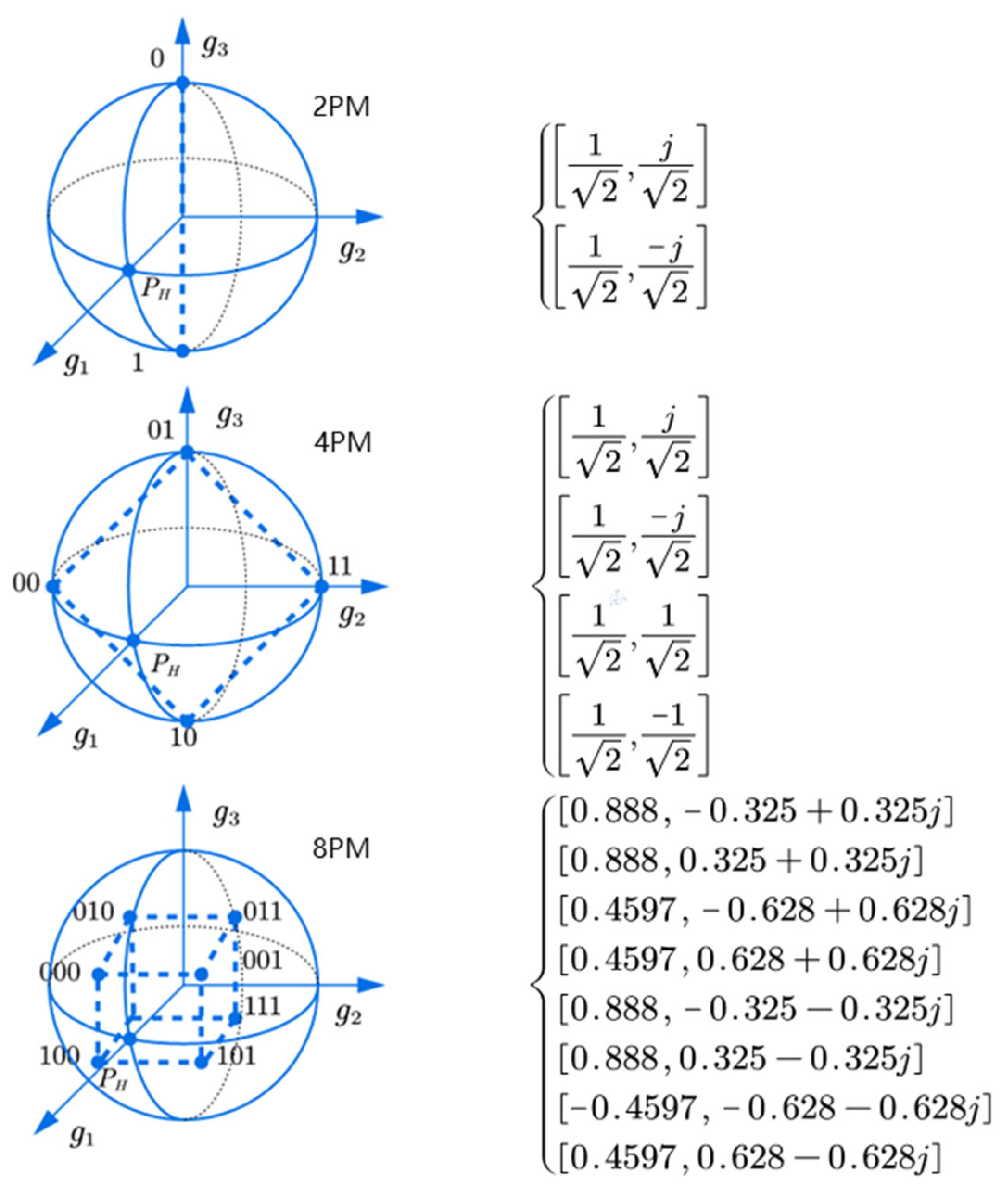
where χ , ψ denotes a geometric descriptor. g 0 represents the radius of the Poincare sphere, and g 1 , g 2 , and g 3 correspond to the three coordinates of the polarization state in the Cartesian coordinate system. In particular, 2 δ i represents the arc length from the polarization constellation point P to P H . t i and φ i denote the longitude and latitude of P on the Poincare sphere, respectively. ϕ i is defined as the angle between the arc and the equatorial plane, as shown in Figure 1.
The polarization constellation points P i ( i = 1 , 2 , , M P ) of order M p are the parameters associated with the polarization phase descriptor, and P = w k 1 w k 2 T , where w k 1 and w k 2 are the weighting factors, as illustrated in Figure 2.

2.2. PAPM Modulation and Demodulation Model

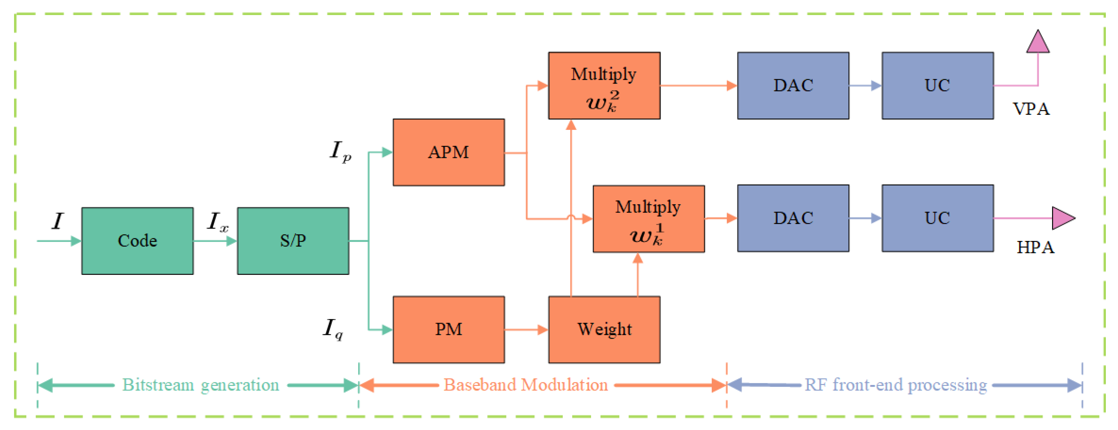
PAPM represents an advanced and efficient strategy for wireless transmission. As depicted in Figure 3, the overall input information bitstream is denoted as I , and the encoded information bitstream is I x , which is first processed by a serial-to-parallel (S/P) converter. The S/P converter splits the stream into two sub-streams: I p and I q . The sub-stream I q is used for PM to determine the polarization state, while the sub-stream I p is used for amplitude-phase modulation (APM), typically quadrature phase shift keying (QPSK), to modulate the signal’s amplitude and phase. Subsequently, the PM signal is split into two identical components. Each component is then multiplied by a distinct weighting factor, tailored to optimize the characteristics of the signal for transmission. This dual-stream approach allows for the simultaneous transmission of information through both the polarization and the conventional amplitude-phase dimensions of the electromagnetic wave. Following this, the signals undergo conversion from digital to analog format using a digital-to-analog converter (DAC). The final step involves up-conversion (UC), which shifts the signals to the desired frequency band to transmit respectively through horizontal polarization antenna (HPA) and vertical polarization antenna (VPA). The specific characteristics of the signals in the vertical and horizontal orientations are as follows:
E H = k = 1 K cos ( γ k ) A k e j 2 π f k t + ϕ 0 ( k ) E V = k = 1 K sin ( γ k ) A k e j 2 π f k t + ϕ 0 ( k ) + φ k
where A k denotes the amplitude value of the carrier f k in the k symbol period, and ϕ 0 ( k ) is the initial phase value of the f k carrier in the k symbol period.
For PAPM demodulation at the receiver side, polarization matching method is used for demodulation. Figure 4 shows the block diagram of the demodulation scheme for PAPM. Firstly, the received signals are first down converted (DC), and then analog-to-digital conversion (ADC) is performed on the signals. Subsequently, the polarized phase descriptors of the two orthogonal signals are extracted, and polarization demodulation uses the maximum likelihood (ML) method. For APM demodulation, the polarization information is removed by using the polarization state matching method. The phase descriptor of the k symbol period is as follows:
γ k R = arctan | y k V | | y k H | φ k R = Ψ ( y k V ) Ψ ( y k H )
The polarization matching method to obtain APM modulation information is shown below:
y k R A P M = cos γ k R sin γ k R e j φ k R H y k = cos γ k R sin γ k R e j φ k R H cos γ k sin γ k e j φ k A k e j ( ω c t + θ k )
where y k is the received signal, and the first term on the right-hand side of the equation is the polarized phase descriptor of the PM demodulated by the maximum likelihood criterion.

2.3. Multi-Parameter Weighted-Type Fractional Fourier Transform Model

The MP-WFRFT is defined as follows:
S 0 ( n ) = F α , V [ X 0 ( n ) ] = ω 0 ( α , V ) + ω 1 ( α , V ) + ω 2 ( α , V ) + ω 3 ( α , V )
where F α , V is the transformation operator of the MP-WFRFT, X 0 denotes the original baseband signal to be encrypted, and X i i = 1 , 2 , 3 denotes the i -th transformation of X 0 . ω l ( α , V ) ( l = 0 , 1 , 2 , 3 ) represents the weight factors, α is the transform order, and V = M V , N V is the transform’s scale vector, where M V = [ m 0 , m 1 , m 2 , m 3 ] and N V = [ n 0 , n 1 , n 2 , n 3 ] . S 0 ( n ) is the transformed MP-WFRFT signal. While conventional Fourier transform (FT) provides a fixed mapping from the time to the frequency domain, fractional Fourier transform (FRFT) introduces flexibility by rotating a signal to any intermediate time-frequency domain. The MP-WFRFT enhances this security framework significantly. It not only performs a rotation, governed by the order α , but also applies complex transformations like twisting, stretching, and shearing, which are determined by the scale vectors V = M V , N V . Therefore, perfect signal reconstruction is only possible for a legitimate receiver who can apply the inverse MP-WFRFT with the precise keys α and V .
The weight factors are as follows:
w l ( α , V ) = 1 T k = 0 T 1 exp ± 2 π j T ( T m k + 1 ) α ( k + T n k ) l k ,   ( l = 0 , 1 , , T 1 )
where T represents the transform period of the MP-WFRFT. Given the invertibility of the MP-WFRFT, it is possible to extract the original discrete signal X 0 ( n ) from Equation (8) provided that the signal S 0 ( n ) is known.
X 0 ( n ) = F α , V [ S 0 ( n ) ]   = ω 0 ( α , V ) S 0 ( n ) + ω 1 ( α , V ) S 1 ( n ) + ω 2 ( α , V ) S 2 ( n ) + ω 3 ( α , V ) S 3 ( n )

2.4. Directional Modulation Model

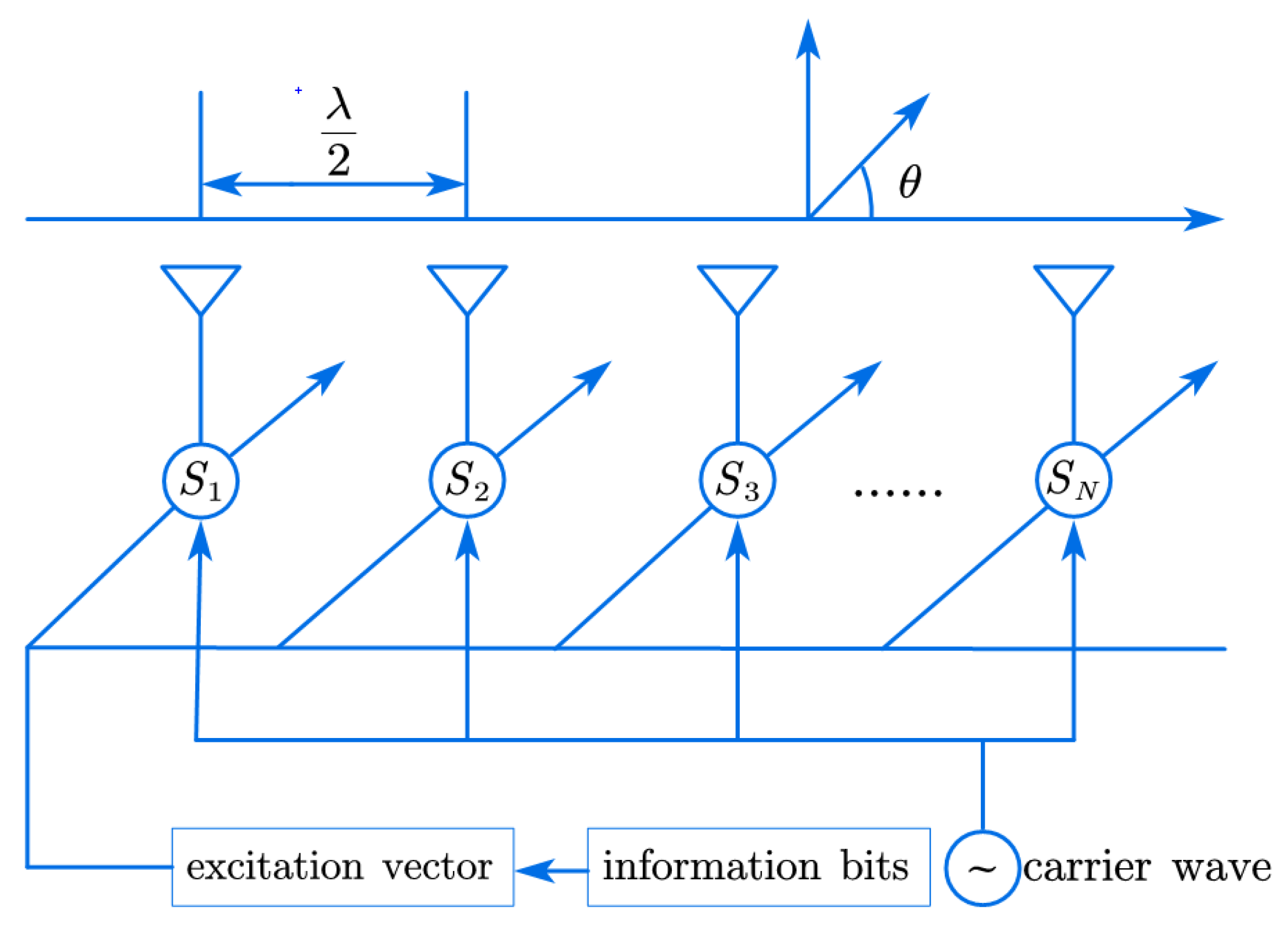
Figure 5 illustrates the model of a uniform linear antenna array. Let N represent the number of elements in the array. The spacing between the array elements d is set to half of the carrier wavelength, and the azimuth angle is denoted by θ . So, the excitation vector is as follows:
S   =   A P U
The channel line-of-sight vector, which is fundamentally determined by the antenna array’s geometry, is given by the array factor (also known as the steering vector) H ( θ ) :
H ( θ ) = e j π 1 N + 1 2 cos θ e j π 2 N + 1 2 cos θ e j 0 e j π N 1 N + 1 2 cos θ e j π N N + 1 2 cos θ T
The array factor H ( θ ) describes the collective phase response of the N -element uniform linear array at a given azimuth angle θ . From this, the normalized array factor P = H θ H ( θ ) , amplitude A = 1 N , and u represents the symbols sent by the transmitter.
Then the signal received by a legal receiver on an azimuth of θ is:
y B = H ( θ ) H S + n B
where n B denotes Gaussian white noise. When the azimuth angle of the eavesdropper is not equal to the azimuth angle of the correct signal, the eavesdropper cannot demodulate the signal properly.

3. Proposed Solution

This section begins with an overview of the fundamental principles of variable polarization modulation. Then, it proceeds to present an in-depth analysis of the impact that the MP-WFRFT parameter settings have on the BER performance within satellite communication systems. Finally, this paper introduces a strategy for integrating MP-WFRFT with DM algorithms.

3.1. The Principle of Variable Polarization Modulation

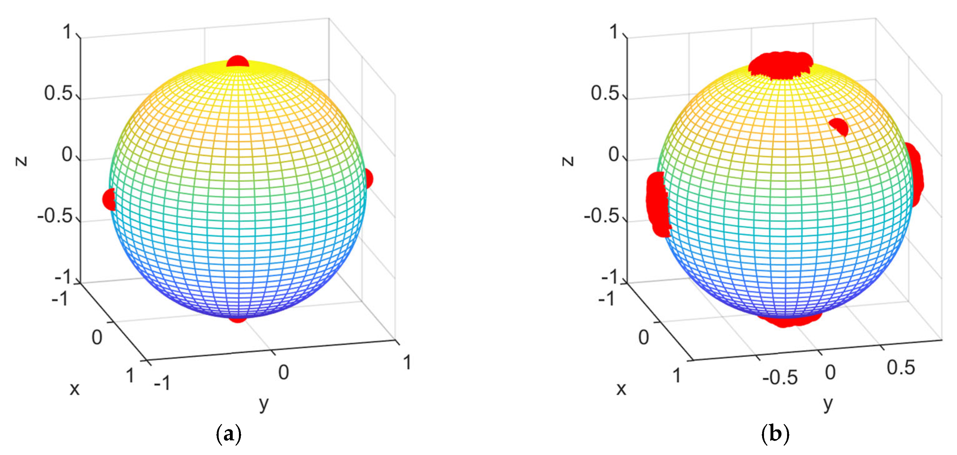
The proposed variable polarization modulation (VPM) technology is specifically designed for advanced satellite communication systems that require high security and robustness, such as military communications, government secure links, and next-generation satellite-to-ground data relays. These applications typically employ dual-polarized antennas capable of generating and receiving arbitrary polarization states, including linear, circular, and elliptical polarizations. By adaptively tuning the polarization state of the transmitted signal, they intelligently create an orthogonality to the polarization pattern of interfering signals. VPM technology precisely controls the amplitude ratio and phase difference of two orthogonal signals by assigning specific digital weighting factors to them. Then, it transmits the signals to a dual-polarization antenna, resulting in the generation of an electromagnetic wave with an arbitrary polarization state. Figure 6 illustrates the constellation diagrams of VPM. Figure 6a–h represent horizontal polarization, vertical polarization, 45 linear polarization, 135 linear polarization, right circular polarization, left circular polarization, right elliptic polarization and left elliptic polarization, respectively. The red dot indicates the corresponding polarization constellation point, and x, y and z denote the coordinate axes of three-dimensional coordinate system.

3.2. Analyzing the Impact of MP-WFRFT Parameter Settings on BER Performance

3.2.1. Analyzing the Impact of MP-WFRFT Scale Vector Parameter Settings on BER Performance

The direction of the cos γ signal is characterized by a transform order of α and a scale vector of V 1 = M V 1 N V 1 , where M V 1 = m 0 m 1 m 2 m 3 , and N V 1 = n 0 n 1 n 2 n 3 . In the direction of the sin γ e j φ signal, the transform order is β with a scale vector of V 2 = M V 2 N V 2 , M V 2 = m 00 m 11 m 22 m 33 , where N V 2 = n 00 n 11 n 22 n 33 . This analysis seeks to investigate the scanning properties of a single parameter within the scale vector in the cos γ signal direction, assuming that the parameter in the sin γ e j φ signal direction is kept constant.
When k in Equation (7) is zero in the case of M V 1 = m 0 m 1 m 2 m 3 , the 0-th term of ω l is as follows:
ω l ( α , V , k = 0 ) = exp ± 2 π j T ( T m 0 + 1 ) α T n 0
From the above equation, it can be seen that the BER performance of the parameter m 0 on the signal is affected by n 0 . In particular, when n 0 is equal to zero, the variation in m 0 has no enhancement on the anti-interception performance of satellite communication.
When k in Equation (7) is greater than zero in the case of M V 1 = m 0 m 1 m 2 m 3 , the other term of ω l is as follows:
ω l ( α , V , k > 0 ) = exp ± 2 π j T k ( α T m k + α l ) + ( T m k + 1 ) α T n k
Based on the equation, the periods associated with m 1 , m 2 , and m 3 are arranged in descending order as follows: P m 1 >   P m 2   > P m 3 .
In the case of N V 1 = n 0 n 1 n 2 n 3 , the term of ω l is as follows:
ω l ( α , V , k ) = exp ± 2 π j T ( T m k + 1 ) α T n k + ( T m k + 1 ) α k l k
By analyzing the equation, it is evident that n k is not directly influenced by k . Consequently, the periods of the four parameters associated with n k are essentially equivalent, which suggests a consistent level of security against eavesdropping for N V 1 .

3.2.2. Analyzing the Impact of MP-WFRFT cos γ and sin γ e j φ Direction Parameter Settings on BER Performance

When signals in directions cos γ and sin γ e j φ pass through the Gaussian white noise channel, the inverse MP-WFRFT is initially applied. Referring to VPM demodulation in Equation (4), it becomes apparent that the sin γ e j φ signal direction component serves as the numerator in the equation for determining the polarization phase descriptor γ , φ , while the cos γ direction signal component functions as the denominator. A minor fluctuation in the cos γ direction parameter can significantly alter the demodulated γ , φ . But the maximum likelihood decision criterion, a standard in variable polarization demodulation, may not fully counteract this susceptibility to error. However, as detailed in previous subsection, the sin γ e j φ direction signal component is subject to a periodic normal error, which is mitigated in two stages: firstly, by correcting the error in the cos γ direction signal component, and subsequently, by the maximum likelihood decision criterion.

3.3. Proposing the Fusion of MP-WFRFT and DM Algorithms Based on the VPAPM Scheme

In this subsection of the study, the DM technique with MP-WFRFT is explored in depth, and BER performance is evaluated for two modulation strategies respectively: PAPM and VPAPM schemes.
  • The Principles of PAPM and VPAPM Schemes
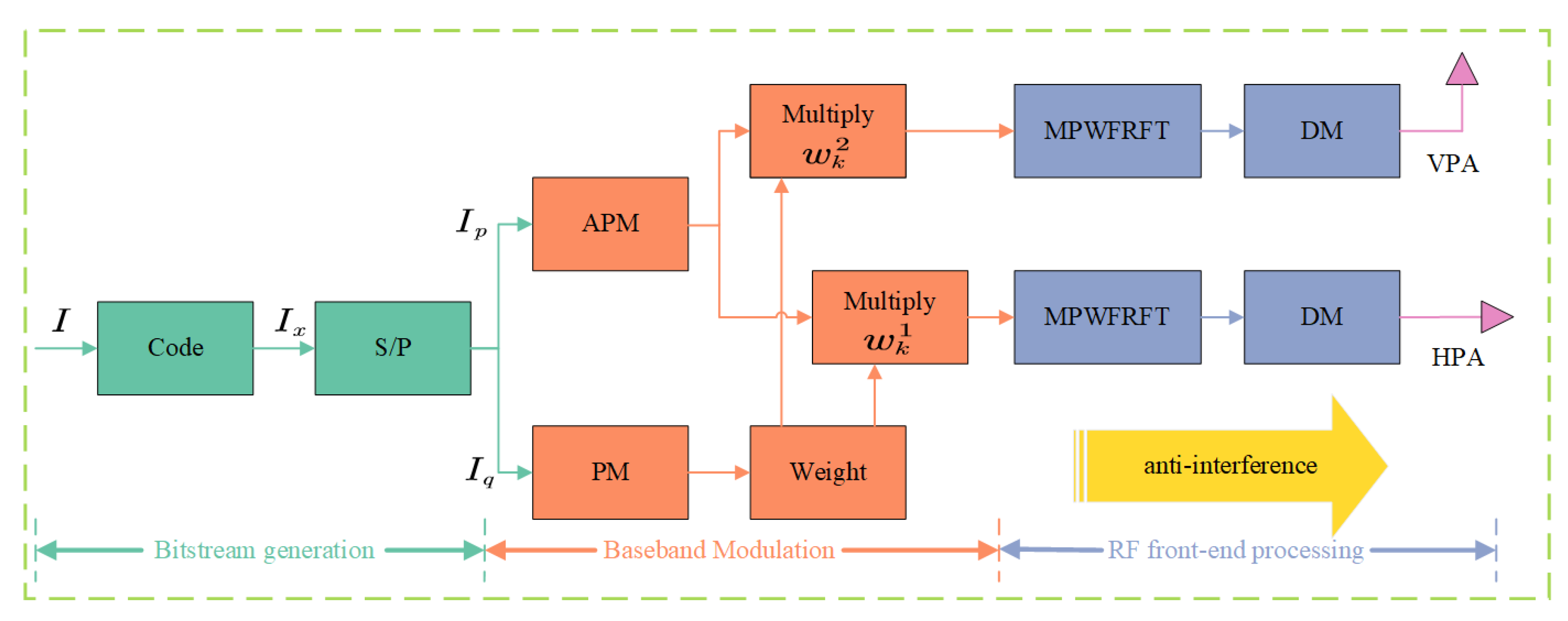
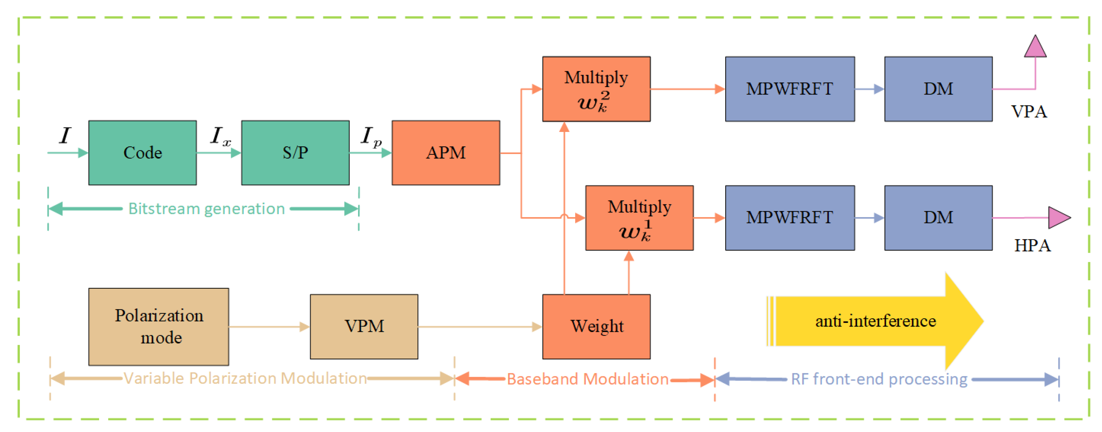
The PAPM modulation scheme is presented in Figure 7 and is in a position to both multiply the information transmission rate and improve the anti-interception performance through the MP-WFRFT and DM algorithms. Furthermore, as can be seen in Figure 8, the VPAPM modulation scheme is capable of adjusting the polarization pattern of the modulated signal adaptively, employing polarization orthogonality to suppress interference. Although satellite channels are susceptible to polarization-dependent loss (PDL) effects, the adoption of pre-compensation techniques can effectively eliminate this impairment. Consequently, under such conditions, VPM is primarily subjected to additive white gaussian noise (AWGN), which endows VPM with considerable advantages in satellite communication systems. Given that the VPAPM scheme employs a hybrid approach combining QPSK modulation and VPM, the derivation of its overall BER necessitates separate consideration of the BER performance attributable to each of these constituent modulation techniques. The BER for VPAPM is given by the following [22]:
S E R = S E R P × R P + S E R Q × R Q R P + R Q
where S E R P is the symbol error rate (SER) attributable to VPM modulation, and S E R Q is the SER attributable to QPSK modulation. R P and R Q represent the number of symbols transmitted per unit time for PM and QPSK, respectively.
First, calculate the theoretical SER for QPSK:
S E R Q = 2 Q S N R Q S N R 2
where M Q = 2 R Q is the modulation order, and SNR is the signal-to-noise ratio (SNR) at the receiver. Q ( x ) = 1 2 π x e t 2 / 2 d t stands for the Gaussian Q-function.
Under the influence of an AWGN channel, the polarization constellation points of the received signal will exhibit a displacement relative to their ideal transmitted positions. The probability density function (PDF) characterizing the locations of these noise-perturbed received constellation points can be expressed as follows [24]:
f ( t i , φ i ) = 1 4 π sin t i e S N R 1 cos t i 2 1 + S N R 1 + cos t i 2
Consider that in the M P -order three-dimensional constellation diagram, each constellation point exhibits central symmetry with respect to the horizontal polarization point P H , and assume that each symbol occurs with equal probability. Due to the adoption of the VPAPM scheme, it is necessary to introduce adaptive constellation point position parameters for polarization modulation. The SER formula is given by
S E R P = 1 M P i = 1 M P S E R P i ( δ i ( S N R ) , ϕ i ( S N R ) )
where δ i and ϕ i are functions of SNR, dynamically selected by an optimization algorithm.
The decision region is defined by the adaptive parameter δ i :
S E P P i = π d i s 0 π 0 2 π f ( t i , φ i ) d φ i d t i + d i s 0 π d i s 0 0 α ( d i s 0 , t i ) f ( t i , φ i ) d φ i d t i , ( M P = 2 ) , j = 1 J 2 d i s 1 j π 0 α ( d i s 0 , d i s 1 j ) f ( t i , φ i ) d φ i d t i + d i s 0 d i s 1 j 0 α ( d i s 0 , t i ) f ( t i , φ i ) d φ i d t i , ( M P > 2 )
α ( d i s 0 , t i ) = arccos tan d i s 0 tan t i
d i s 0 = 1 2 dis T
d i s 11 = 2 δ i , d i s 12 = π 2 δ i , ( M P = 4 , J = 2 ) d i s 11 = arccos [ cos ( 2 δ i ) + sin ( 2 δ i ) tan ( 2 δ i ) ] 1 + sec 2 ( A / 2 ) tan 2 ( 2 δ i ) , d i s 12 = 2 δ i , d i s 13 = π 2 δ i , ( M P 8 , J = 3 )
where M P = 2 R P is the polarization modulation order; d i s 0 represents half the spherical distance between adjacent constellation points, denoting the spherical distance between a polarization constellation point and its j -th decision region boundary point; J represents the number of decision region boundary points when employing the ML decision criterion; and A is the spherical angle:
A = P i P H P j = 2 arcsin sin ( dis T / 2 ) sin ( 2 δ i )
The polarization constellation point positions are dynamically selected by solving an optimization problem:
min δ i , ϕ i S E R P ( δ i , ϕ i , SNR )
The optimization objective is the minimization of S E P P , subject to the following constraints:
(1)
The constellation points lie on the Poincare sphere, satisfying t i = t ( δ i , ϕ i ) and φ i = φ ( δ i , ϕ i ) .
(2)
The constellation structure maintains central symmetry.
It can be observed that adaptive optimization solely influences the integration boundaries and constellation point parameters pertinent to S E P P . The VPAPM scheme, by selecting appropriate transmit polarization states, aims to counteract channel polarization mode dispersion (PMD) or PDL. This ensures that the M P polarization states arriving at the receiver preserve their ideal relative geometric configuration to the greatest extent possible, thereby minimizing the loss of signal power.
2.
Analyzing the BER Performance of MP-WFRFT and DM fusion algorithm
The receiver side is the inverse process of the transmitter side mentioned above. MP-WFRFT and DM are independent of each other because the former processes the baseband signals, while the latter deals with the RF signals. The BER of the MP-WFRFT and DM fusion algorithm consists of two main components: one is the inherent BER of the MP-WFRFT, and the other is the BER impact of the DM algorithm on the MP-WFRFT. Since the MP-WFRFT and DM algorithms are independent of each other, the total BER under Gaussian white noise channel conditions can be expressed by the following equation:
B E R = k B E R 1 B E R 2 + B E R 2
where B E R 1 represents the BER of the DM algorithm under Gaussian white noise channel conditions, while B E R 2 denotes the BER of the MP-WFRFT algorithm under the same channel conditions. The term k refers to the BER accumulation factor, which is typically an empirical parameter obtained by fitting to extensive simulation or experimental data. In practical signal processing or communication systems, an error in one module may disproportionately amplify or alter the impact of errors occurring in subsequent modules. The parameter k precisely attempts to capture this complex interaction effect. For example, if the output of the DM algorithm serves as a critical input or parameter for the MP-WFRFT algorithm, errors in DM may cause the nature of errors in MP-WFRFT, when they occur, to be more severe or their probability to be higher. In addition, k is a parameter that must be determined through empirical calibration. We calibrate k through a series of controlled-variable simulation experiments:
(1)
Simulation 1 (Obtaining B E R 1 ): Activate only the DM system (by setting the MP-WFRFT module to a passthrough mode). Simulate the BER for an eavesdropper at various offset angles ( θ e ), yielding B E R 1 ( θ e ,   S N R ) .
(2)
Simulation 2 (Obtaining B E R 2 ): Activate only the MP-WFRFT system (by setting the DM to an omnidirectional transmission mode). Simulate the BER for an eavesdropper using an incorrect security key ( α e , V e ), yielding B E R 2 ( α e , V e , S N R ) .
(3)
Simulation 3 (Obtaining B E R t o t a l ): Run the complete, integrated system. Simulate an eavesdropper who is simultaneously at an incorrect angle and using an incorrect key, yielding B E R t o t a l ( θ e ,   α e ,   V e ,   S N R ) .
(4)
Calculate k: Calculate the value of k over a large number of parameter points (different S N R , θ e , α e , etc.) using the formula   k = ( B E R t o t a l B E R 2 ) / ( B E R 1 B E R 2 ) .
In our simulations, to simplify the analysis, we select the average value of k, evaluated over a set of typical scenarios, for our assessment.
While the proposed scheme offers superior security, it is important to acknowledge the associated trade-offs in terms of system complexity and power consumption:
(1)
Computational complexity: In MP-WFRFT, the complexity of computing the weight w is O 1 , and that of the weighted sum is O N , while the fast Fourier transform (FFT) has a computational complexity of O ( N log N ) . As N , O ( N ) O ( N log N ) . Consequently, the time complexity of MP-WFRFT is O ( N log N ) , primarily determined by the length N of the discrete sequence. Moreover, both the time and space complexities of the DM algorithm are O N A (where N A is the number of antenna elements), corresponding to linear complexity. Thus, it is evident that the integrated MP-WFRFT and DM algorithm exhibits a relatively low complexity, facilitating its practical implementation.
(2)
Power consumption: Increased digital processing and the need to drive a multi-element antenna array for DM will lead to higher power consumption. However, this is partially mitigated by one of the core components of our scheme. The use of PAPM is known to improve the power efficiency of the satellite’s high-power amplifier (HPA) by reducing the peak-to-average power ratio (PAPR) compared to that of some traditional modulation formats.

4. Simulation Experiment Results and Discussion

This subsection first analyses the impact of the MP-WFRFT algorithm on the signal characteristics of both two-dimensional and three-dimensional constellation diagrams. Secondly, it offers a comparative analysis of the DM algorithm in conventional versus polarization modulation. Thirdly, the security performance of the MP-WFRFT algorithm for the VPAPM scheme is examined. Finally, the paper proposes directional variable polarization modulation with MP-WFRFT.

4.1. The Influence of the MP-WFRFT Algorithm on Signal Constellation Map Distribution

4.1.1. Parameter Scanning Characteristics of the MP-WFRFT Algorithm in Two-Dimensional Constellation Map

For the QPSK signal, the transform order of the MP-WFRFT is α , and the scale vector is V = M V N V . The values of MP-WFRFT parameters are provided in Table 2.
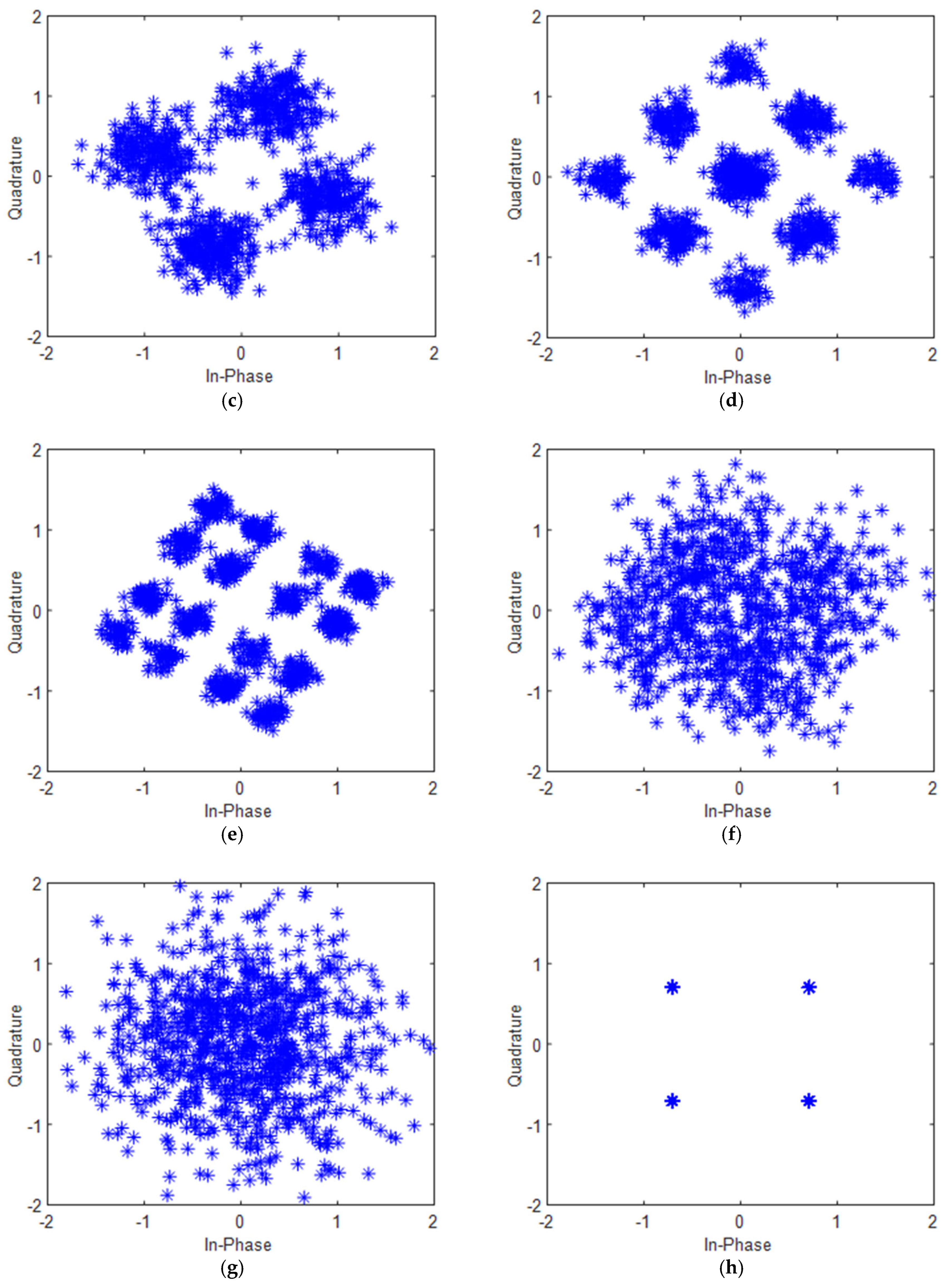
The simulation outcomes are illustrated in Figure 9. As the parameter α varies, the constellation diagram undergoes transformations characterized by rotation, expansion, and compression of the original four constellation points. Firstly, the changes become increasingly evident when the values of α grow larger, as depicted in Figure 9b,c. Secondly, when α is modified alongside the scaling factors M V and N V , the constellation points exhibit a significant transformation, evolving into nine entirely new constellation points, which is shown in Figure 9d. Thirdly, further adjustments to α , M V , and N V induce another round of splitting, leading to the emergence of sixteen distinct constellation points, as seen in Figure 9e, the configuration of which effectively mimics a 16QAM signal. In scenarios where the values of α , M V , and N V are randomized, the constellation points display a mixing behavior, resembling a Gaussian distribution, as evidenced in Figure 9f,g. Notably, Figure 9h, a share identical distributions of constellation points. However, Figure 9h represents a rotated version of the constellation depicted in Figure 9a, achieved through the application of a 180° rotational transformation.

4.1.2. Parameter Scanning Characteristics of the MP-WFRFT Algorithm in Three-Dimensional Constellation Map

In the case of the 4-PM signal, the MP-WFRFT applies horizontal transformation with an order α and a scale vector V 1 = M V 1 N V 1 , while vertical transformations are governed by an order β and a scale vector V 2 = M V 2 N V 2 . The specific values of MP-WFRFT parameters are detailed in Table 3.
The simulation results are presented in Figure 10. Firstly, when the transformation orders α and β vary, the distribution of constellation points becomes increasingly diffuse and gradually blends together, as illustrated in Figure 10b,c. Secondly, upon introducing scale vectors, the constellation points are dispersed across the Poincare sphere and trend toward a Gaussian distribution, as shown in Figure 10d,e. Thirdly, when the transformation orders α and β are both set to one, the constellation points are reminiscent of a 2-PM constellation map, as depicted in Figure 10f. However, the coordinates of the constellation points do not align with the standard 2-PM configuration. As the complexity of the transformation orders and scale vectors increases, the distribution of constellation points increasingly resembles a Gaussian distribution, as demonstrated in Figure 10g. Furthermore, Figure 10h, a exhibit the same constellation point distribution, but Figure 10h displays the constellation points after applying a 180 ° rotational transformation to Figure 10a.

4.2. The Influence of DM on Conventional and Polarization Modulation

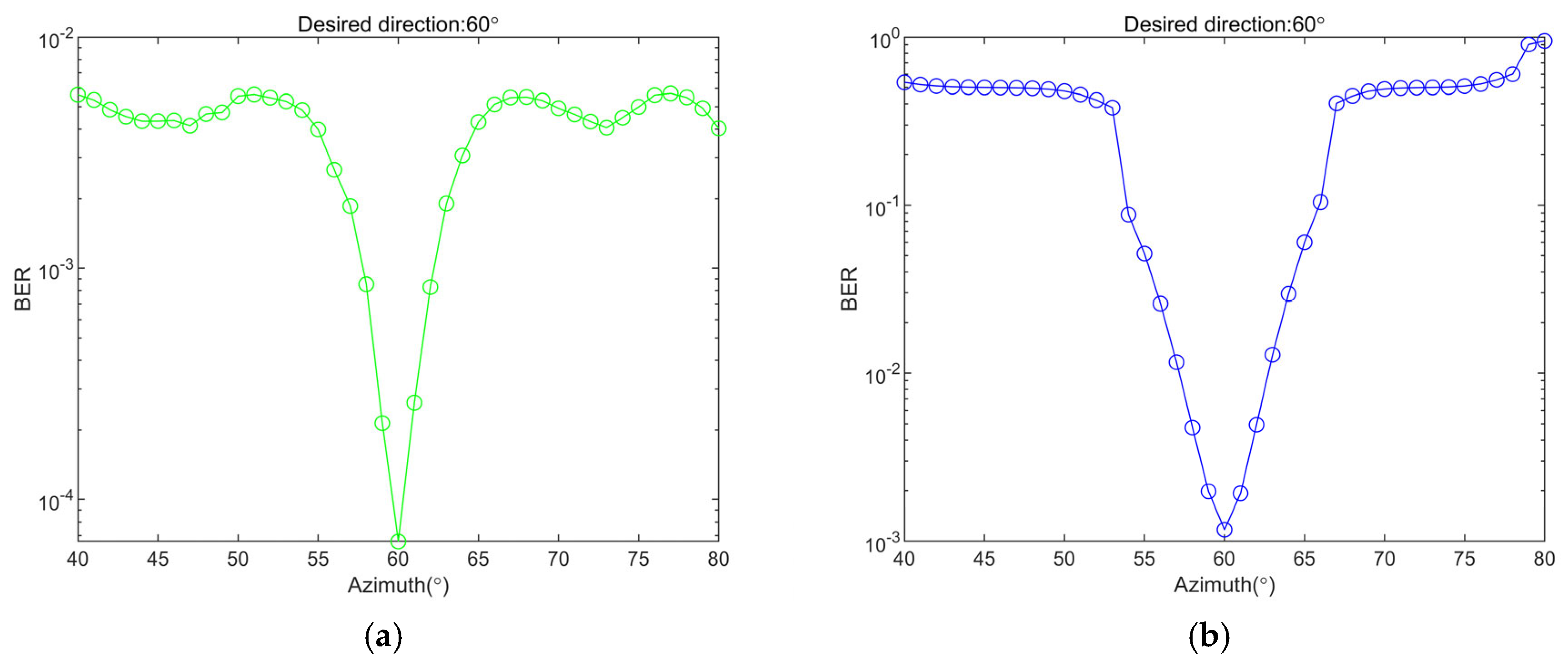
The combination of PM with DM is compared against the QPSK plus DM scheme. In this comparison, the desired reception direction is set to 60°, and the azimuth scan range is defined as 40°–80°. The simulation results illustrating this comparison are presented in Figure 11.
From the above Figure 11, it is evident that the overall BER performance of the PM plus DM scheme is superior to that of the QPSK plus DM scheme under the same azimuthal parameters. Locally, the BER curve for PM plus DM is steeper and rises more rapidly near the desired reception direction.

4.3. BER Performance Comparison of MP-WFRFT Parameters Based on the VPAPM Scheme

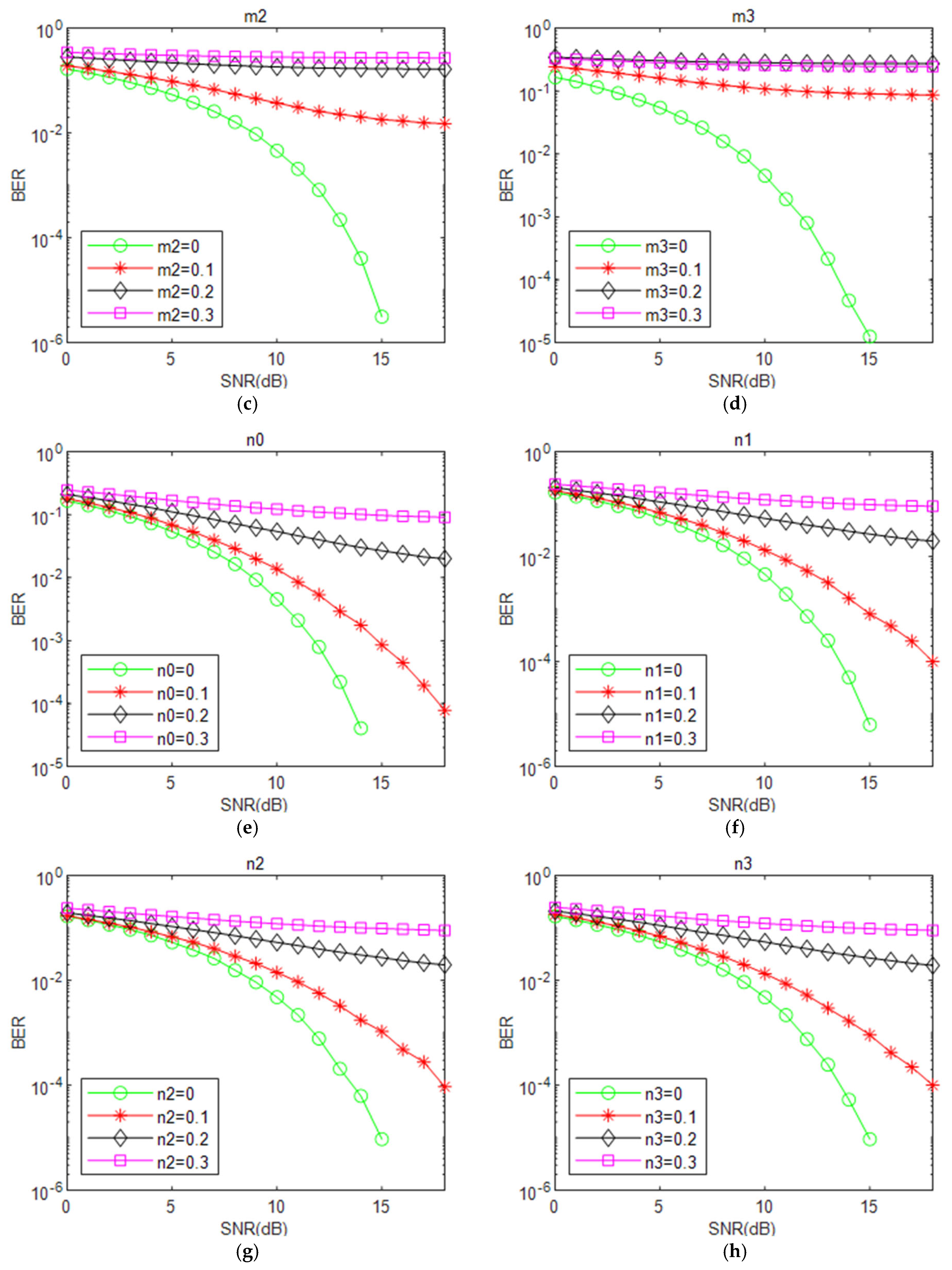
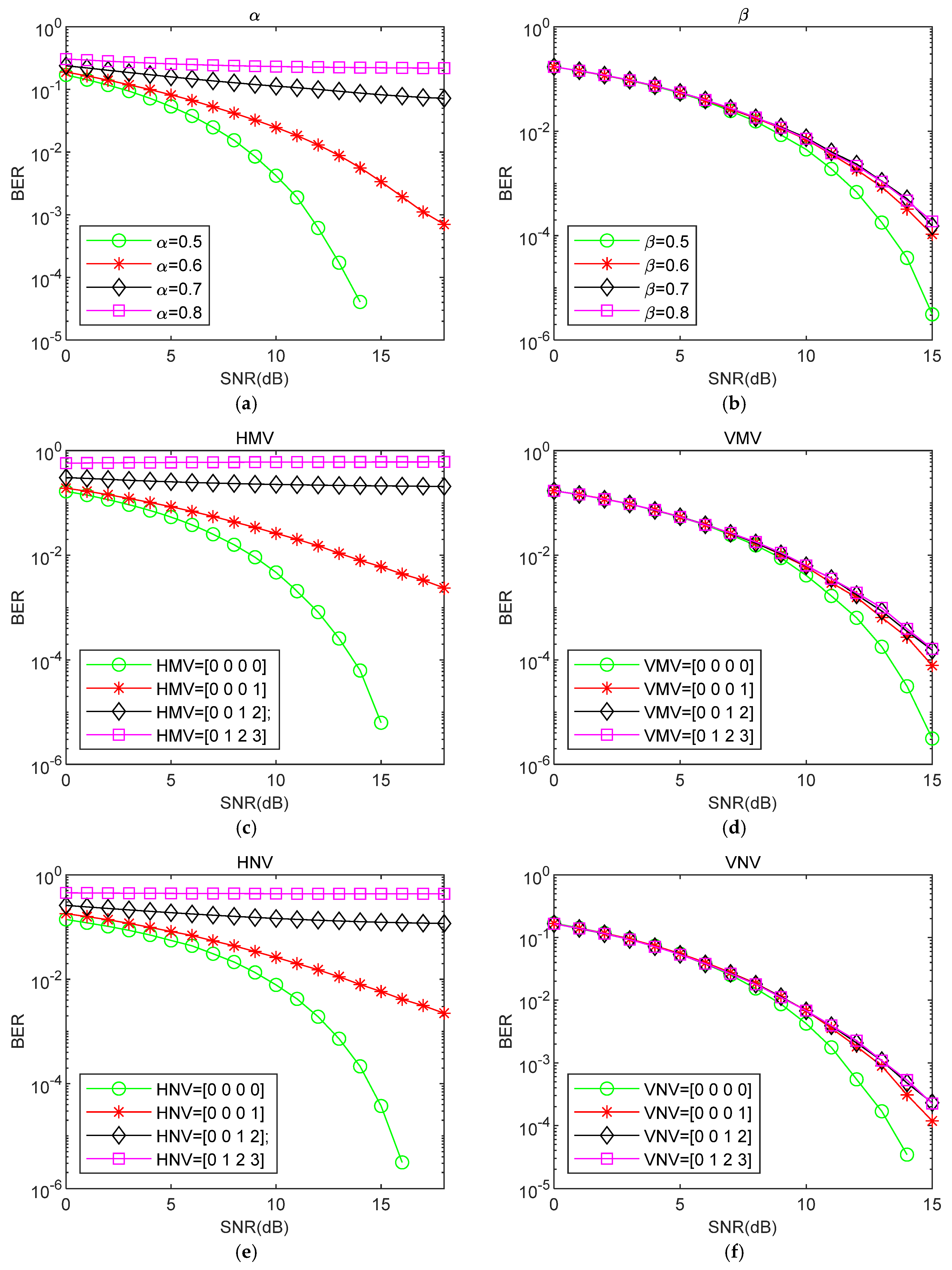
Firstly, the scanning characteristics of a single parameter in the scale vector are investigated for the VPAPM scheme, with the results presented in Figure 12. Secondly, under the same parameter scanning interval, the effects of MP-WFRFT parameter settings on the BER performance are explored in the cos γ and sin γ e j φ directions, and the results are illustrated in Figure 13a–f.
The following conclusions can be drawn from Figure 12:
(1)
Changing the parameter m 0 in the horizontal and vertical directions has no impact on the BER performance of the received signal, as shown in Figure 12a.
(2)
From Figure 12b–d, it is observed that the BER performance for receiver m 2 is the best, followed by m 3 , while m 4 has the worst performance.
(3)
The effects of parameters n 0 , n 1 , n 2 , and n 3 on the BER performance at the receiver are nearly the same, as shown in Figure 12e–h.
The analysis of Figure 13 reveals that the BER performance curves for α , M V 1 , and N V 1 in the cos γ direction change significantly, whereas those in the sin γ e j φ direction show only minor variations for β , M V 2 , and N V 2 , despite the same parameter scanning interval. Compared to the sin γ e j φ direction, the cos γ direction is more effective in enhancing the system’s anti-interception performance.
The above two sets of simulations demonstrate that the MP-WFRFT algorithm, when applied to the VPAPM scheme, exhibits robust parameter anti-detection capabilities. Even when the VPM method is known, there are still eighteen free parameter combinations that need to be scanned. If the interceptor is also unfamiliar with the signal transformation method, the difficulty of demodulating the intercepted signal becomes even more substantial.

4.4. Directional Variable Polarization Modulation with MP-WFRFT

To address the limitations of the current satellite communication systems, such as inadequate resistance to scanning, low secrecy rates, and weak decryption resistance, this paper proposes an enhanced approach by integrating the MP-WFRFT and DM algorithms based on the VPAPM scheme. The simulation parameters are configured as detailed in Table 4.
The simulation results are presented in Figure 14. Notably, an azimuth of 54 ° represents the desired receiver position. Meanwhile, the correct transformation orders of the MP-WFRFT cos γ and sin γ e j φ directions are respectively α = 0.5 and β = 0.5 . From the analyses in Figure 14, it is evident that the fusion algorithm of MP-WFRFT and DM significantly enhances the anti-interception performance compared to using a single secure transmission technique. Specifically, the BER is improved by at least an order of magnitude when the signal-to-noise ratio exceeds 10 dB, which demonstrates the robustness and effectiveness against interception.
When the azimuth angle in DM is set to a specific value, the BER curves for both the horizontal transformation order α ( α = 0.5, 0.6, 0.7, 0.8) and the vertical transformation order β ( β = 0.5, 0.6, 0.7, 0.8) over the same scanning interval are observed. Notably, alterations in the cos γ direction result in a marked improvement in the BER performance of the satellite communication system. In contrast, the BER curves for the sin γ e j φ direction exhibit a phenomenon characterized by clustering, which does not contribute to significant enhancement in the anti-interception performance. Furthermore, it is evident that random changes in the parameters of the MP-WFRFT algorithm, coupled with a substantial deviation of the DM azimuth from the ideal direction, can have a profound impact on the BER performance of the VPAPM modulation-based scheme.

5. Conclusions

The exploration of anti-jamming and anti-interception technologies has emerged as a pivotal area of focus within the realm of satellite communications, advancements in which are crucial in ensuring the highest level of security for the transmission of information. This paper delves into the MP-WFRFT algorithm, which is known to induce rotation, diffusion, and aliasing in two-dimensional and three-dimensional signal constellation maps. In comparison to the amalgamation of DM with conventional modulation techniques, the integration of PM and DM offers distinct advantages in bolstering information security. Building upon the VPAPM framework, the scale vector parameters of MP-WFRFT are evaluated and ranked from highest to lowest in terms of their resistance to interception: m 1 > m 2 > m 3 > m 4 , n 1 n 2 n 3 n 4 . Furthermore, based on an in-depth analysis of the simulation results, the cos γ direction is more effective for improving the anti-interception performance of satellite communications systems. More importantly, this paper proposes a secure satellite transmission technique via directional variable polarization modulation with MP-WFRFT.
The proposed scheme demonstrates superior performance over individual algorithms within a signal-to-noise ratio range of 0–10 dB. Beyond 10 dB, the anti-interception performance is improved by at least one order of magnitude. In summary, the scheme presented in this paper has the potential to significantly enhance spectral efficiency and electromagnetic countermeasures within the dynamic challenges of complex battlefield environments.

Author Contributions

Conceptualization, Z.H. and Z.L. (Zukun Lu); methodology, Z.H. and Z.L. (Zukun Lu); investigation, Z.H., Z.L. (Zukun Lu), and X.L. (Xiangjun Li); resources, X.Z. and Z.L. (Zongnan Li); writing—original draft preparation, Z.H.; writing—review and editing, Z.H., Z.L. (Zukun Lu), X.L. (Xiangjun Li), X.Z., Z.L. (Zongnan Li), and X.L. (Xiaohui Liu); visualization, Z.H. and X.L. (Xiaohui Liu); supervision, Z.L. (Zukun Lu) and X.L. (Xiaohui Liu). All authors have read and agreed to the published version of the manuscript.

Funding

This research was supported by the National Natural Science Foundation of China under Grant U20A20193.

Data Availability Statement

The data presented in this study are available on request from the corresponding author.

Conflicts of Interest

The authors declare no conflicts of interest.

References

  1. Kua, J.; Loke, S.W.; Arora, C.; Fernando, N.; Ranaweera, C. A survey of next-generation computing technologies in space-air-ground integrated networks. ACM Comput. Surv. 2023, 56, 1–40. [Google Scholar]
  2. He, J.; Cheng, N.; Yin, Z.; Zhou, C.; Zhou, H.; Quan, W.; Lin, X.-H. Service-oriented network resource orchestration in space-air-ground integrated network. IEEE Trans. Veh. Technol. 2024, 73, 1162–1174. [Google Scholar] [CrossRef]
  3. Reddy, Y.M.; Raj, V.H.; Thethi, H.P.; Gupta, S.; Maan, P.; Ghani, R.H. Low earth orbit satellite networks: A new era in global communication. In Proceedings of the 2023 10th IEEE Uttar Pradesh Section International Conference on Electrical, Electronics and Computer Engineering (UP CON), Gautam Buddha Nagar, India, 1–3 December 2023; Volume 10. [Google Scholar]
  4. Shen, Z.; Jin, J.; Tan, C.; Tagami, A.; Wang, S.; Li, Q.; Zheng, Q.; Yuan, J. Internet of things in space: A review of opportunities and challenges from satellite-aided computing to digitally-enhanced space living. Sensors 2021, 21, 8117. [Google Scholar]
  5. Chai, F.; Zhang, Q.; Yao, H.; Xin, X.; Gao, R.; Guizani, M. Joint multi-task offloading and resource allocation for mobile edge computing systems in satellite IOT. IEEE Trans. Veh. Technol. 2023, 72, 7783–7795. [Google Scholar] [CrossRef]
  6. Li, X.; Lu, Z.; Yuan, M.; Liu, W.; Wang, F.; Yu, Y.; Liu, P. Tradeoff of code estimation error rate and terminal gain in SCER attack. IEEE Trans. Instrum. Meas. 2024, 73, 8504512. [Google Scholar] [CrossRef]
  7. Shen, N.; Chen, L.; Liu, J.; Wang, L.; Tao, T.; Wu, D.; Chen, R. A review of global navigation satellite system (GNSS)-based dynamic monitoring technologies for structural health monitoring. Remote Sens. 2019, 11, 1001. [Google Scholar] [CrossRef]
  8. Giordani, M.; Zorzi, M. Satellite communication at millimeter waves: A key enabler of the 6g era. In Proceedings of the 2020 International Conference on Computing, Networking and Communications (ICNC), Big Island, HI, USA, 17–20 February 2020; pp. 383–388. [Google Scholar]
  9. Wang, J.; Jiang, C.; Kuang, L. High-mobility satellite-UAV communications: Challenges, solutions, and future research trends. IEEE Commun. Mag. 2022, 60, 38–43. [Google Scholar] [CrossRef]
  10. Tedeschi, P.; Sciancalepore, S.; Di Pietro, R. Satellite-based communications security: A survey of threats, solutions, and research challenges. Comput. Networks 2022, 216, 109246. [Google Scholar] [CrossRef]
  11. Zou, Y.; Zhu, J.; Wang, X.; Hanzo, L. A survey on wireless security: Technical challenges, recent advances, and future trends. Proc. IEEE 2016, 104, 1727–1765. [Google Scholar] [CrossRef]
  12. Mukherjee, A.; Fakoorian, S.A.A.; Huang, J.; Swindlehurst, A.L. Principles of physical layer security in multiuser wireless networks: A survey. IEEE CST 2014, 16, 1550–1573. [Google Scholar] [CrossRef]
  13. Namias, V. The fractional order Fourier transform and its application to quantum mechanics. IMA J. Appl. Math. 1980, 25, 241–265. [Google Scholar] [CrossRef]
  14. McBride, A.C.; Kerr, F.H. On Namias’s fractional Fourier transforms. IMA J. Appl. Math. 1987, 39, 159–175. [Google Scholar] [CrossRef]
  15. Lohmann, A.W. Image rotation, Wigner rotation, and the fractional Fourier transform. J. Opt. Soc. Am. A-Opt. Image Sci. Vision. 1993, 10, 2181–2186. [Google Scholar] [CrossRef]
  16. Shih, C.-C. Fractionalization of Fourier transform. Opt. Commun. 1995, 118, 495–498. [Google Scholar] [CrossRef]
  17. Mei, L.; Sha, X.; Zhang, N. Research on the application of 4-weighted fractional Fourier transform in communication system. Sci. China-Inf. Sci. 2010, 53, 1251–1260. [Google Scholar] [CrossRef]
  18. Ding, B.; Mei, L.; Sha, X. Secure communication system based on alterable-parameter 4-weighted fractional Fourier transform. Inf. Technol. J. 2010, 9, 158–163. [Google Scholar] [CrossRef]
  19. Fang, X.; Zhang, N.; Sha, X.; Chen, D.; Wu, X.; Shen, X. Physical layer security: A WFRFT-base cooperation approach. In Proceedings of the 2017 IEEE International Conference on Communications (ICC), Paris, France, 21–25 May 2017. [Google Scholar]
  20. Zhang, X.; Zhang, B.; Guo, D.; Wang, Y. Application of polarization modulation in satellite communication. In Proceedings of the 2017 First International Conference on Electronics Instrumentation Information Systems (EIIS), Harbin, China, 3–5 June 2017. [Google Scholar]
  21. Wei, D.; Feng, C.; Guo, C. A polarization-amplitude-phase modulation scheme for the power amplifier energy efficiency enhancement. In Proceedings of the 15th International Symposium on Wireless Personal Multimedia Communications, Taipei, Taiwan, 24–27 September 2012. [Google Scholar]
  22. Wei, D.; Zhang, M.; Fan, W.; Huang, W. A spectrum efficient polarized PSK/QAM scheme in the wireless channel with polarization dependent loss effect. In Proceedings of the 2015 22nd International Conference on Telecommunications, Sydney, NSW, Australia, 27–29 April 2015. [Google Scholar]
  23. Liu, F.; Wang, X.; Li, R.; Wang, B. Multilevel continuous polarization modulation with high spectral efficiency in the depolarization channels. IEEE Access. 2018, 6, 33002–33014. [Google Scholar] [CrossRef]
  24. Zhao, S.; Zeng, Z.; Feng, C.; Liu, F. Power amplifier energy efficiency enhancement via adaptive polarization-QAM modulation scheme in OFDM systems. IEEE Access. 2017, 5, 23751–23763. [Google Scholar] [CrossRef]
  25. DA, X.; Wang, H.; Luo, Z. Dual-polarized satellite security trans mission scheme based on double layer multi-parameter weighted-type fractional Fourier transform. J. Electron. Inf. Technol. 2019, 41, 1974–1982. [Google Scholar]
  26. Qiu, B.; Cheng, W.; Zhang, W. Decomposed and distributed directional modulation for secure wireless communication. IEEE Trans. Wirel. Commun. 2024, 23, 5219–5231. [Google Scholar] [CrossRef]
  27. Hafez, M.; Yusuf, M.; Khattab, T.; Elfouly, T.; Arslan, H. Secure spatial multiple access using directional modulation. IEEE Trans. Wirel. Commun. 2018, 17, 563–573. [Google Scholar] [CrossRef]
  28. Liu, F.; Wang, L.; Xie, J. Directional modulation technique for linear sparse arrays. IEEE Access. 2019, 7, 13230–13240. [Google Scholar] [CrossRef]
  29. Zhuang, Z.; Junshan, L.; Shilian, W.; Guojiang, X. Security-enhanced directional modulation based on two-dimensional M-WFRFT. China Commun. 2024, 21, 229–248. [Google Scholar] [CrossRef]
  30. Kalantari, A.; Soltanalian, M.; Maleki, S.; Chatzinotas, S.; Ottersten, B. Directional modulation via symbol-level precoding: A way to enhance security. IEEE J. Sel. Top. Signal Process. 2016, 10, 1478–1493. [Google Scholar] [CrossRef]
  31. Wang, W.-Q.; Zheng, Z. Hybrid MIMO and phased-array directional modulation for physical layer security in mmWave wireless communications. IEEE J. Sel. Areas Commun. 2018, 36, 1383–1396. [Google Scholar] [CrossRef]
  32. Shu, F.; Wu, X.; Li, J.; Chen, R.; Vucetic, B. Robust synthesis scheme for secure multi-beam directional modulation in broadcasting systems. IEEE Access. 2016, 4, 6614–6623. [Google Scholar] [CrossRef]
  33. Christopher, R.M.; Borah, D.K. Iterative convex optimization of multi-beam directional modulation with artificial noise. IEEE Commun. Lett. 2018, 22, 1712–1715. [Google Scholar] [CrossRef]
  34. Luo, Z.; Wang, H.; Lv, W. Directional polarization modulation for secure transmission in dual-polarized satellite MIMO systems. In Proceedings of the 2016 8th International Conference on Wireless Communications Signal Processing (WCSP), Yangzhou, China, 13–15 October 2016. [Google Scholar]
  35. Luo, Z.; Pei, Z.; Zou, B. Directional polarization modulation for secure dual-polarized satellite communication. In Proceedings of the 2019 International Conference on Communications, Information System and Computer Engineering (CISCE), Haikou, China, 5–7 July 2019. [Google Scholar]
  36. Collett, E. Field Guide to Polarization; SPIE Press: Bellingham, WA, USA, 2005. [Google Scholar]
  37. Brosseau, C. Fundamentals of Polarized Light: A Statistical Optics Approach; John Wiley: Hoboken, NJ, USA, 1998. [Google Scholar]
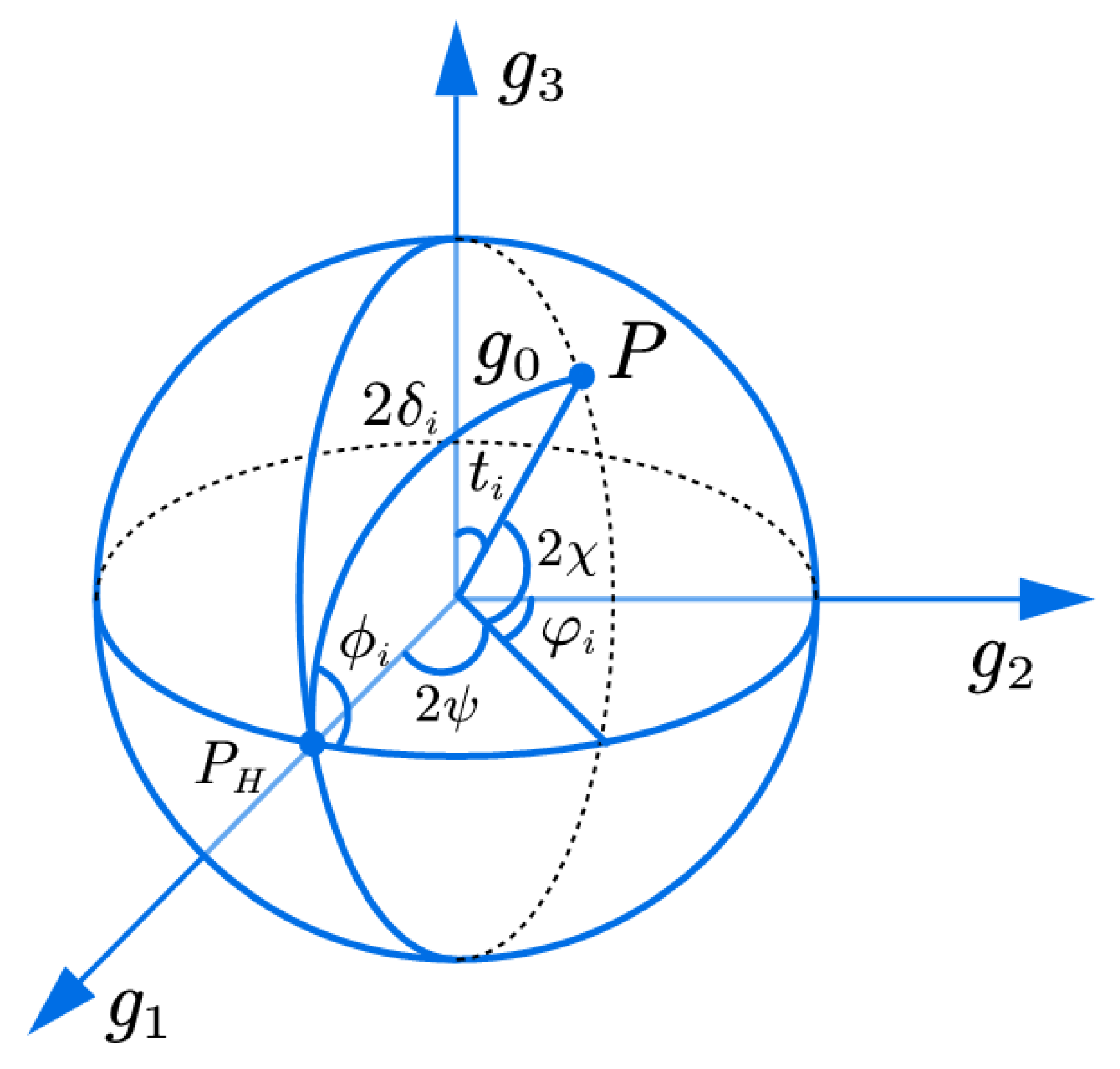
Figure 1. Poincare polarization sphere for Stokes parameter coordinate mapping.
Aerospace 12 00690 g001
Figure 2. Constellation point weight mapping.
Aerospace 12 00690 g002
Figure 3. Block diagram of PAPM transmitter.
Aerospace 12 00690 g003
Figure 4. Block diagram of PAPM receiver.
Aerospace 12 00690 g004
Figure 5. Model of antenna array.
Aerospace 12 00690 g005
Figure 6. Constellation diagrams of VPM.
Aerospace 12 00690 g006
Figure 7. Block diagram of directional polarization modulation transmitter based on MP-WFRFT.
Aerospace 12 00690 g007
Figure 8. Block diagram of directional variable polarization modulation transmitter based on MP-WFRFT.
Aerospace 12 00690 g008
Figure 9. Two-dimensional constellation diagram of QPSK signal after MP-WFRFT transformation.
Aerospace 12 00690 g009aAerospace 12 00690 g009b
Figure 10. Three-dimensional constellation diagram of 4-PM signal after MP-WFRFT transformation.
Aerospace 12 00690 g010aAerospace 12 00690 g010b
Figure 11. BER of hybrid modulation. (a) PM + DM. (b) QPSK + DM.
Aerospace 12 00690 g011
Figure 12. BER curves of scale vectors scanning characteristic of VPAPM scheme.
Aerospace 12 00690 g012aAerospace 12 00690 g012b
Figure 13. BER curves of cos γ (H) and sin γ e j φ (V) directions for VPAPM scheme.
Aerospace 12 00690 g013
Figure 14. Performance of the proposed algorithm. (a) cos γ direction (horizontal direction). (b) sin γ e j φ direction (vertical direction).
Aerospace 12 00690 g014
Table 1. Comparison of different physical layer security schemes.
TechniqueSecurity Domain(s)Key Space SizeAnti-Interception GainLimitations
(DM) [34,35]SpatialLow (direction)ModerateSusceptible to multi-antenna eavesdroppers
Artificial noise (AN) DM [26]SpatialModerate (direction + AN)HighReduces power efficiency; AN can interfere with legitimate users
WFRFT-based security [25]Time-frequency (TF)High (transform orders/vectors)HighNo spatial security; susceptible to frontal attack at the correct location
Our proposed schemeMulti-domain (spatial + TF Polarization)Very high (combined keys)Very high (synergistic)Increased system complexity
Table 2. MP-WFRFT parameter list of two-dimensional constellation map.
Positive α MVNVInverse
(b)0.05[0 0 0 0][0 0 0 0](a)
(c)0.20[0 0 0 0][0 0 0 0](a)
(d)2.90[0 0 1.3 0][0 0 0 4.7](a)
(e)1.95[0 0 1 0][3.5 0 0 0](a)
(f)0.05[6 5 0 0][0 0 4 3](a)
(g)1.00[6 5 4 0][0 4 3 2](a)
……………………(a)
(h)2.00[6 5 4 3][6 5 4 3](a)
Table 3. MP-WFRFT parameter list of three-dimensional constellation map.
Positive α MV1NV1 β MV2NV2Inverse
(b)0.05[0 0 0 0][0 0 0 0]0.05[0 0 0 0][0 0 0 0](a)
(c)0.20[0 0 0 0][0 0 0 0]0.20[0 0 0 0][0 0 0 0](a)
(d)0.30[6 0 0 0][0 5 0 0]0.30[6 0 0 0][0 5 0 0](a)
(e)0.40[6 5 0 0][0 0 4 3]0.40[6 5 0 0][0 0 4 3](a)
(f)1.00[6 5 4 0][0 4 3 2]1.00[6 5 4 0][0 4 3 2](a)
(g)1.50[6 5 4 3][6 5 4 3]1.50[6 5 4 3][6 5 4 3](a)
………………………………(a)
(h)2.00[0 0 0 0][0 0 0 0]2.00[0 0 0 0][0 0 0 0](a)
Table 4. Parameter list of fusion algorithm.
Situation α or β β or α Azimuth   (°)Curve
(a)0.500.5054°Green
(b)0.560.5054°Red
(c)0.580.5054°Yellow
(d)0.600.5054°Blue
(e)0.500.5060°Black
(f)0.560.5060°Purple
Disclaimer/Publisher’s Note: The statements, opinions and data contained in all publications are solely those of the individual author(s) and contributor(s) and not of MDPI and/or the editor(s). MDPI and/or the editor(s) disclaim responsibility for any injury to people or property resulting from any ideas, methods, instructions or products referred to in the content.