Abstract
This paper presents a preliminary investigation into the aeroelastic behavior of a tailless flying wing equipped with a rotating wingtip. Based on the configuration of Innovative Control Effectors (ICE) aircraft, an aeroelastic model of the tailless flying wing with a rotating wingtip has been developed. Both numerical simulation and wind tunnel tests (WTTs) are employed to study the aeroelastic characteristics of this unique design. The numerical simulation involves the coupling of computational fluid dynamics (CFD) and implicit dynamic approaches (IDAs). Using the CFD/IDA coupling method, aeroelastic response results are obtained under different flow dynamic pressures. The critical flutter dynamic pressure is identified by analyzing the trend of the damping coefficient, with a focus on its transition from negative to positive values. Additionally, the critical flutter velocity and flutter frequency are obtained from the WTT results. The critical flutter parameters, including dynamic pressure, velocity, and flutter frequency, are examined under different wingtip rotation frequencies and angles. These parameters are derived using both the CFD/IDA coupling method and WTT. The results indicate that the rotating wingtip plays a significant role in influencing the flutter behavior of aircraft with such a configuration. Research has shown that the rotation characteristics of the rotating wingtip are the primary factor affecting its aeroelastic behavior, and increasing both the rotation frequency and rotation angle can raise the flutter boundary and effectively suppress flutter onset.
1. Introduction
The tailless flying wing represents an unconventional aerodynamic configuration characterized by wing–body integration, absence of vertical and horizontal tails, and multiple control surfaces. This design features a flat, streamlined shape with the entire wing and fuselage functioning as a single lifting surface. By eliminating traditional control surfaces such as the vertical and horizontal tails, air resistance is minimized, and the lift-to-drag ratio is significantly improved, resulting in enhanced aerodynamic efficiency. Additionally, the absence of vertical tails and the high degree of wing–body integration lead to a substantial reduction in radar cross-section (RCS), thereby providing excellent stealth capability. In addition, the elimination of the tail structure contributes to a lighter overall structure. Compared to conventional aircraft layouts, tailless flying wing configurations offer superior aerodynamic efficiency, stealth performance, and structural weight reduction. To achieve the desired maneuverability in tailless flying wing aircraft, it is essential to identify an appropriate control surface that can provide yaw moment to compensate for the absence of vertical tails, thereby meeting high-maneuverability design requirements. Consequently, many researchers have proposed the aerodynamic layout of rotating wingtips. The rotating wingtip is positioned at the outermost ends of the wing. When activated on one side, it increases induced drag, thereby generating the necessary yaw moment for the aircraft. The tailless flying wing with rotating wingtips has many advantages, which are high aerodynamic efficiency, good maneuverability, and excellent stealth capability.
Some famous programs, institutions, and organizations have carried out a lot of research on the tailless flying wing with rotating wingtips. The Innovative Control Effectors (ICE) program is one of them. The ICE program was a joint research effort between Wright Laboratory and the Naval Air Warfare Center, aimed at exploring innovative aerodynamic control concepts for tailless flying wing aircraft [1]. The primary objective of this program was to develop, demonstrate, and validate innovative aerodynamic flight control effector suites for tailless flying wing aircraft [2]. The rotating wingtip was a key focus of the ICE program’s research efforts. Under the traction of this program, Lockheed Martin Aeronautics contributed significantly to developing a six-degree-of-freedom aerodynamic model, which featured a highly swept wing with a 65-degree sweep on the leading edge and 25-degree chevron shaping on the trailing edge [3]. The NATO task groups AVT-239 and AVT-350 have conducted extensive research work on control aspects related to ICE aircraft [4,5,6,7,8]. Some scholars have also researched rotating wingtips. The research by Yu et al. [9] revealed that the rotating wingtip holds significant potential as a yawing control surface, which is attributed to its superior yawing efficiency. Wang et al. [10] studied the triaxial augmentation ability of the active disturbance rejection control technique on the tailless layouts with rotating wingtips to achieve high control performance for supersonic tailless aircraft. All these studies aim to solve the control problem. Over the past few years, many researchers have focused on the aerodynamic performance and flow-field characteristics of wingtips. To solve the aerodynamic problem of Pitch-Break, Yuan et al. [11] adopted a rotating wingtip as an auxiliary aileron, which had minor fluctuations during the Pitch-Break zone compared with a conventional aileron. Zuo and Wang [12] investigated the aerodynamic characteristics and control effectiveness of a tailless flying wing with rotating wingtips by using experimental results. Nikolic [13,14] positioned the wing strakes at the main wingtips and also made them movable about an axis perpendicular to the main wing chord plane. This design aligns with the concept of rotating wingtips. He researched the aerodynamic characteristics and optimization of the movable wingtip strake. Chauhan and Martins [15] investigated the aerodynamic shape optimization of a wing with a wingtip using the CFD method. Wang et al. [16] provided an ideal vortex-center detection criterion for studying wingtip vortex instability or energy transfer characteristics associated with vortex wandering. Gao et al. [17] analyzed the aerodynamic interaction mechanisms of a wingtip using the reformulated vortex particle method. Zaccara et al. [18] focused on wingtip vortices and used experimental methods to investigate the effectiveness of synthetic jet actuation. Schröder et al. [19] presented results from a combined experimental and numerical investigation of the flow around a wingtip to generate a system of two closely spaced concentrated tip vortices. However, regarding the aeroelasticity, it appears that only the authors of this paper have conducted some research in this area, based on the available literature. Wang et al. [20,21] applied the CFD/CSD method and frequency method to analyze the divergence and flutter regularity of a tailless flying wing with a rotating wingtip. In the previous research stage, we focused solely on using simulation methods to investigate the aeroelastic problem and did not employ the WTT to verify the relevant results and conclusions.
This paper employs the ICE aircraft configuration and develops an aeroelastic model for a tailless flying wing with a rotating wingtip. Both numerical simulation and WTT are utilized to analyze the aeroelastic response and identify the critical flutter parameters. The aeroelastic characteristics of the rotating wingtip are investigated under various rotation frequencies and angles.
2. CFD/IDA Coupling Method
In the past three years, fluid–structure interaction (FSI) techniques have developed quickly. Many scholars have used the CFD/CSD coupling method to solve the aeroelastic problem [22,23,24]. The CFD/CSD coupling method relies on modal shapes and has a high requirement for the purity of the modal shapes. However, the CFD/IDA coupling method does not depend on the mode shapes and has good stability and reliability. The CFD/IDA coupling method was previously published by our team [25]. This paper applies this method to analyze the aeroelastic response of a tailless flying wing with a rotating wingtip. The CFD/IDA coupling strategy adopts a partitioned approach, which integrates available disciplinary algorithms. This strategy has been validated and used for solving many complicated fluid or structural problems [26]. This makes the solution result highly reliable, portable, and able to be parallelized.
The aerodynamic forces are calculated using the CFD method. The Navier–Stokes equations are the basic equations of the CFD method. The Navier–Stokes equations, which are derived using the three basic conservation laws of fluid mechanics [27], will be briefly described in the next section. Furthermore, the structural dynamic equation is derived from the d’Alembert principle, and the structural response is computed by the IDA.
2.1. Computational Fluid Dynamics
In CFD, the mass equation, momentum equation, and energy equation are three fundamental equations that describe the conservation of mass, the momentum of fluid, and the transfer and conservation of energy in a Newtonian fluid.
where is the air density, and is the flow velocity vector, with . u, v, and w are the flow velocities in Cartesian coordinate system directions, and is the normal direction of the boundary surface. p is the atmospheric pressure, , is the specific heat ratio, is the total energy, and is the viscous stress. is the coefficient of the thermal conductivity, and T is the temperature.
Combining Equations (1)–(3), the Navier–Stokes equations can be obtained in integral form as follows:
Equation (4) can be solved using the finite volume method. For transient simulations, it is necessary to discretize the governing equations in both space and time. Spatial discretization is achieved using a second-order upwind scheme. Temporal discretization involves integrating each term in the differential equations over a time step. It employs an implicit time integration scheme, ensuring stability and accuracy in the simulation of unsteady flows. To account for the complex effects of turbulence on aerodynamic forces, the Spalart–Allmaras (SA) turbulence model, which is a one-equation model [28] that solves a modeled transport equation for the kinematic turbulent viscosity, is utilized. The SA turbulence model is employed because of its validated accuracy of external aerodynamic flows, computational efficiency suited to large-scale unsteady simulations, and robust near-wall behavior on deforming meshes. The SA model has also been demonstrated to be successful in our previous work [25]. In both time-marching aeroelastic calculations, the mesh must be updated at each time step to reflect the dynamic changes in the flow field. This mesh deformation is accomplished using the spring method, which provides an efficient way to maintain the integrity of the computational grid while accommodating fluid–structure interactions.
2.2. Implicit Dynamic Approach
Implicit direct-integration dynamic analysis can be used to study the structural dynamic response or flutter. A brief introduction to the theoretical process of the IDA for solving flutter will be given. Flutter is a behavior that results from the coupling of the inertial force (), elastic force (), and unsteady aerodynamic force () [29]. In addition, the structural damping force () should be considered. The d’Alembert principle [30] is used to form the dynamic equilibrium equation (Equation (5)). The virtual work principle [31] is applied to rewrite the dynamic equilibrium equation (Equation (6)). Finite element approximation is based on interpolations, whereby the displacement, position, and other variables at any material point are defined by a finite number of nodal variables. Uppercase superscripts are used to refer to individual nodal variables or nodal vectors. Hence, the displacement field can be written as . So, the basic equations (Equations (7) and (8)) of the IDA can be derived.
where is a virtual velocity field; is the current density of the material at a given point; , , and are the displacement, velocity, and acceleration at the point, respectively; is the current damping of the structure at the point; is the frequency at the point; is a set of shape functions; is a set of nodal displacements; n is the index of the shape function; and m is the index of the nodal displacement.
Implicit operators available for the time integration of the dynamic problem include the Hilbert–Hughes–Taylor operator [32] and the backward Euler operator.
where is the sum of all the Lagrange multiplier forces associated with the degree of freedom (n). The operator definition is completed using the Newmark formula for displacement and velocity integration as follows:
where , , and . The IDA uses Equations (10) and (11) to calculate the displacement at time . The unsteady aerodynamic force terms ( and ) are obtained using Equation (4) at times t and .
3. Judgment Criteria
For the time solution of flutter, the convergence and divergence trends of the structural vibration response are usually applied to judge the equal-amplitude vibration under critical flutter states through artificial observation. However, during the process of using the CFD/IDA coupling method to calculate the critical flutter parameters, it is necessary to determine criteria to judge the critical flutter state by programming methods. Figure 1 shows the structural vibration response when the flow dynamic pressure is close to the critical flutter dynamic pressure. When the structural vibration response is convergent, the slope is less than 0; when the structural vibration response is divergent, the slope is greater than 0; when the structural vibration response is of equal amplitude, the slope is theoretically equal to 0. Therefore, it is necessary to fit the linear function expression of the upper envelope of the structural vibration response. The Hilbert transformation [33] is adopted to obtain the data points of the upper envelope of the structural vibration response, and the polynomial fitting method is used to fit these data points to obtain the linear function expression.
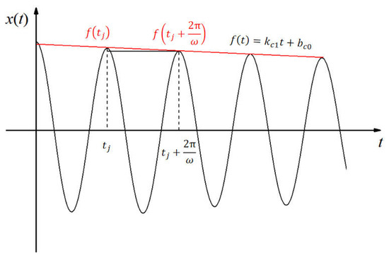
Figure 1.
Structural vibration response curve under critical flutter state.
Assume the linear function expression of polynomial fitting is as follows:
Take the natural logarithm on the right side of the above expression and use Taylor expansion.
Then, according to the definition of the decay rate, the decay rate can be obtained by a formula that involves the slope , the intercept , and the vibration angular frequency .
There is a relationship between the damping coefficient and the decay rate , .
4. Structure Configuration and Aeroelastic Model
The ICE aircraft is an all-wing, high-sweep, and tailless configuration. Figure 2 illustrates the configuration and geometrical data of the ICE aircraft. The aircraft is equipped with several control devices, including an all-moving wingtip (AMT), leading-edge flaps (LEFs), spoiler-slot deflectors (SSDs), and elevons. In this paper, the AMT is called a “rotating wingtip”, a term derived from the unique motion characteristics of this component. Given its descriptive accuracy, the term “rotating wingtip” is deemed more appropriate for use in this context. The leading edge has a 65-degree sweep angle. The wing span is 11.30 in. (287 mm), and the wing root chord is 8.50 in. (216 mm). The mean aerodynamic chord () is 12.17 in. (309 mm) and the moment reference point (MRP) is located at 0.46 .
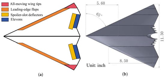
Figure 2.
The configuration and geometrical data of ICE aircraft [4,34]. (a) Configuration; (b) geometrical data.
According to the configuration and geometrical data, a tailless flying wing with a rotating wingtip has been designed in this paper. The configuration only retains the RWT while eliminating other control devices such as LEFs, SSDs, and elevons. This simplification is intended to focus solely on the aeroelastic behavior of the tailless flying wing with a rotating wingtip, isolating this single variable for research. The geometrical data, shown in Figure 2b, is a 1:37 scale model of the Lockheed Martin ICE-101 planform. However, using the 1:37 scale model would result in a size of the ICE that is too small to effectively study aeroelastic behavior. Therefore, through extensive calculations and optimizations, the size of the tailless flying wing with a rotating wingtip has been carefully determined. These calculations and optimizations are limited to the cross-section condition of the WTT, wind speed condition, and structural aeroelastic behavior. The test section cross-sectional dimensions are 1400 × 1200 mm, and the wind speed range is 6∼60 m/s. Figure 3 gives the structural configuration and data of the tailless flying wing with a rotating wingtip. The mid-span is 630 mm, the wing root chord is 1354 mm, and the rotating wingtip root chord is 228 mm. The rotation axis is positioned at the midpoint of the wingtip root chord.
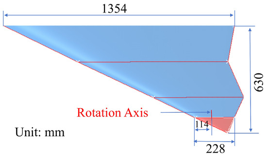
Figure 3.
Structural configuration and data of the tailless flying wing with a rotating wingtip.
The detailed structure of the aeroelastic model has been further designed based on the structural configuration and data of the tailless flying wing with a rotating wingtip. The aeroelastic model (Figure 4) comprises two main components: the main load-bearing structure and the aerodynamic shape structure. The main load-bearing structure contains a control mechanism, a dual-beam frame, and a rotating wingtip. The control mechanism consists of two bearing brackets, one rocking arm, one axle, one U-shaped spring, and one U-shaped spring bracket. One end of the axle features a 40 mm long thread for connecting the rotating wingtip, which is fixed by the nut preload. The thread and nut fastening design structure allows for easy adjustment of different deflection angles of the rotating wingtip. The aerodynamic shape structure has five wing boxes. A foam block is bonded to the leading and trailing edges to maintain the aerodynamic shape. Each wing box is connected to the dual-beam frame through a single-point binding connection. Heat-shrinkable skin is bonded to the edges of each wing box to provide a smooth surface. The aeroelastic model is mounted onto the wing tunnel turntable using a fastener component. Table 1 gives the material and mass of all the parts of the tailless flying with a rotating wingtip.
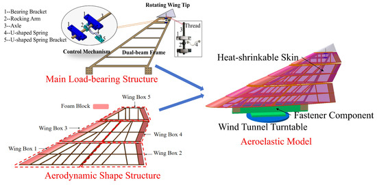
Figure 4.
The aeroelastic model of the tailless flying wing with a rotating wingtip.

Table 1.
The material and mass of the tailless flying wing with a rotating wingtip.
To enable the adjustment of different rotation frequencies of the rotating wingtip, four U-shaped springs are designed in this paper. During the WTT, one or more combinations of these U-shaped springs have been applied. Figure 5 shows the U-shaped spring used for the WTT.
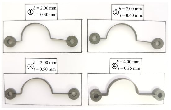
Figure 5.
The U-shaped springs (1–4) used for the WTT.
In this paper, both numerical simulation and a WTT are employed to analyze the aeroelastic response and identify the critical flutter parameters. In order to accomplish this, some numerical simulation models are established. The aerodynamic forces are calculated using the CFD method, while the structural response is computed through the IDA method. Both the fluid model and the finite element model, as shown in Figure 6, are developed for numerical simulation. For the WTT, a wind tunnel model is required, and Figure 7 shows the installation of the aeroelastic model in the wind tunnel.
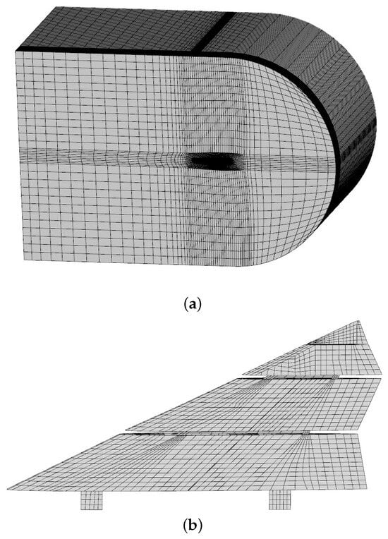
Figure 6.
The simulation models of the tailless flying wing with a rotating wingtip. (a) Fluid model; (b) finite element model.
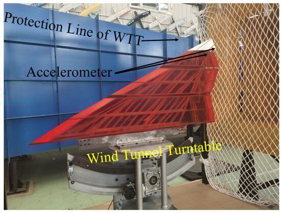
Figure 7.
The aeroelastic model of the WTT.
5. Experimental Instrumentation
This paper employed the GVT to identify the modal frequencies and shapes. The data-acquisition system is a Siemens LMS Simcenter SCADAS Mobile and Recorder. The manufacturer of the equipment is Siemens Industry Software B.V., a company based in Breda, The Netherlands. The equipment has 24 simultaneous channels for capturing multi-point signals. Miniature IEPE accelerometers are used, and their specifications are provided in Table 2.
Table 2.
Specification parameters of accelerometer.
The WTT is conducted to investigate the aeroelastic response of different flow velocities. The type is a low-speed, closed-circuit wind tunnel with overall dimensions of 21 m (length) × 7.5 m (width) × 4 m (height). As shown in Figure 8, the test section measures 1.4 m in width and 1.2 m in height. The wind speed can be regulated from 6 m/s to 60 m/s with an accuracy of ±0.3 m/s. The flow uniformity of the wind tunnel is approximately 0.5%, and the turbulence intensity is about 1.0%.
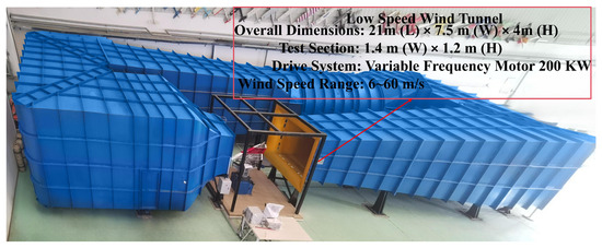
Figure 8.
Low-speed wind tunnel of Dalian University of Technology.
6. Results
The CFD/IDA coupling method is employed for numerical simulation, while the WTT is utilized for experimental validation. The aeroelastic response results under different rotation frequencies and rotation angles are investigated.
6.1. Simulation Results
6.1.1. Different Rotation Frequencies of the RWT
In order to study the aeroelastic behavior under different rotation frequencies, four types of rotation characteristics of the rotating wingtip with increasing frequency are defined. Figure 9 gives two key modes of the tailless flying wing with a rotating wingtip. The first mode (Mode 1) is the first bending mode of the wing. The second mode (Mode 2) is the rotating mode of the wingtip. The frequency of Mode 1 () is 3.02 Hz, and the frequencies of Mode 2 () are 3.31 Hz, 3.55 Hz, 3.82 Hz, and 4.13 Hz, respectively.
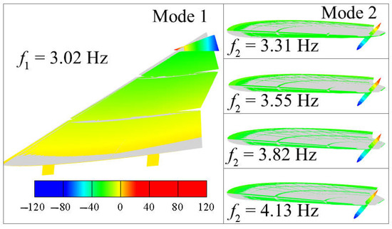
Figure 9.
The modal results of different rotation frequencies.
During aerodynamic simulation, the grid number directly affects the accuracy and efficiency of the calculation results. So, mesh independence analysis is required, and three aerodynamic meshes with different node numbers are established in Figure 10. The coarse grid has 146,301 nodes, the medium grid has 438,096 nodes, and the fine grid has 2,157,366 nodes.
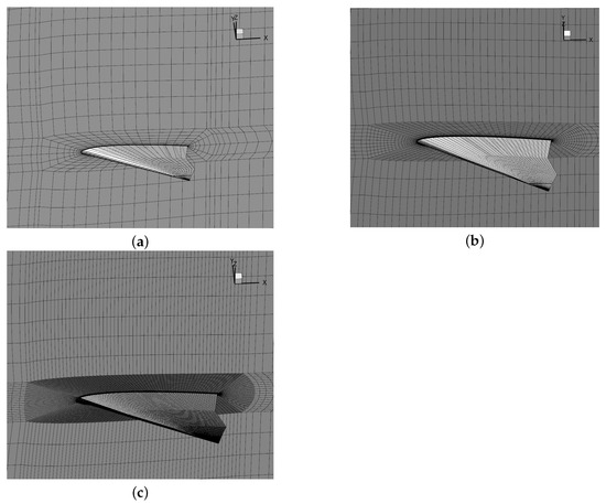
Figure 10.
Three aerodynamic meshes with different node numbers. (a) Coarse grid (146,301 nodes); (b) medium grid (438,096 nodes); (c) fine grid (2,157,366).
After conducting mesh independence analysis, the pressure coefficients are obtained. Figure 11 presents the pressure coefficients of three aerodynamic meshes. The RWT in the figure represents the rotating wingtip. From the figure, the pressure coefficients of the three meshes are essentially identical. To ensure both computational efficiency and accuracy, the medium grid is selected for the CFD/IDA coupling analysis process.
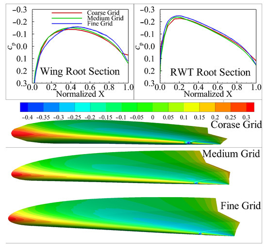
Figure 11.
The pressure coefficient of three aerodynamic meshes.
To observe the structural vibration response under different flow dynamic pressures, monitor points (Figure 12) are selected on the wing and rotating wingtip (RWT), and the two monitor points are also the positions of the acceleration sensors for the WTT. The monitor point of the wing is abbreviated as MPW, and the monitor point of RWT is abbreviated as MP-RWT.
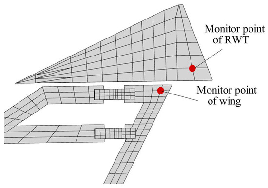
Figure 12.
The monitor points of the wing and RWT.
The CFD/IDA coupling method is applied to calculate the aeroelastic response results of the rotation frequencies 3.31 Hz, 3.55 Hz, 3.82 Hz, and 4.13 Hz. The Fourier transform is performed on the time–response data to gain the frequency domain results. Figure 13 shows the aeroelastic response results at a rotation frequency of 3.55 Hz. From the figure, the trend of structural vibration with increasing flow dynamic pressure can be obtained. The sign changes of the first-order term coefficient in the polynomial fitting, from negative to positive, characterize the critical flutter state. The corresponding damping coefficient under the critical flutter state can be obtained from Equation (15). The accompanying frequency–response curves yield the vibration frequencies under the different flow dynamic pressures. The results for 3.31 Hz and 3.82 Hz are listed in Figure A1 and Figure A2, respectively. To facilitate the determination of the critical flutter dynamic pressure and flutter frequency, the damping coefficients and vibration frequencies under various dynamic pressures have been summarized. Figure 14 shows the vibration frequencies and damping coefficients under different dynamic pressures calculated by using the vibration response results of the MPW and MP-RWT. The figure is a double ordinate diagram. The left vertical axis represents “frequency”, while the right vertical axis represents “damping coefficient”. The horizontal axis is divided into three sections, corresponding to the flow dynamic pressures at rotation frequencies of 3.31 Hz, 3.55 Hz, and 3.82 Hz, respectively. So, the flutter characteristics under different rotation frequencies are determined. Table 3 gives the flutter characteristics of different rotation frequencies. Collectively, these data support the conclusion that raising the rotation frequency of the wingtip enlarges the flutter boundary.
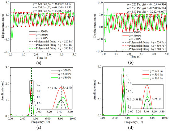
Figure 13.
Aeroelastic response results at the rotation frequency of 3.55 Hz. (a) Time–response curves of the MPW; (b) time–response curves of the MP-RWT; (c) frequency–response curves of the MPW; (d) frequency–response curves of the MP-RWT.
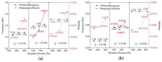
Figure 14.
Under different flow dynamic pressures, the vibration frequencies and damping coefficients of different rotation frequencies. (a) The results of the MPW; (b) the results of the MP-RWT.
Table 3.
Flutter characteristics of different rotation frequencies.
However, from Figure 15, as the flow dynamic pressure increases, the structural vibration response consistently remains in a convergent state. Once the rotation frequency of the wingtip exceeds a threshold, the flutter is completely suppressed, and the flutter behavior does not occur. Consequently, both the critical flutter dynamic pressure and flutter frequency increase with the increasing rotation frequency of the wingtip.
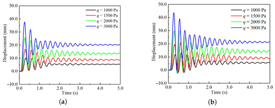
Figure 15.
Aeroelastic response results at the rotation frequency of 4.13 Hz. (a) Time–response curves of the MPW; (b) time–response curves of the MP-RWT.
This subsection investigated the aeroelastic regulation of different rotation frequencies. According to the aeroelastic response results, as the rotation frequency increases, the critical flutter dynamic pressure continues to rise until flutter no longer occurs, and the flutter frequency also increases.
6.1.2. Different Rotation Angles of the RWT
Based on the condition of the wingtip rotation frequency of 3.55 Hz, the aeroelastic response under different rotation angles is assessed. The modal frequencies of rotation angles and are 3.54 Hz, while the modal frequency of rotation angle 30° is 3.53 Hz. Figure 16 shows the modal results of different rotation angles. With an increase in the rotation angles, the rotation frequency changes only slightly, but the modal shape changes obviously.
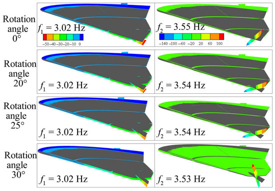
Figure 16.
The modal results of different rotation angles.
When the wingtip deflection angle is (Figure 11), the pressures on the upper and lower surfaces of the wing root section and the RWT root section are basically equal, with the surface pressure difference being nearly zero. When the RWT deflects, the turbulence generated at the wingtip propagates to both the upper and lower surfaces of the wing and wingtip itself, resulting in a significant pressure difference. Figure 17, Figure 18 and Figure 19 show the change in the pressure coefficient and pressure distribution under different RWT rotation angles. The figures of the pressure coefficient clearly reveal the pressure distribution of the tailless flying wing with a rotating wingtip when the RWT deflects. The primary cause of the pressure difference change is the airflow separation and the induced effect on the wing due to the deflection of RWT.
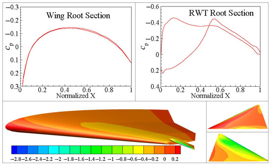
Figure 17.
The pressure coefficient at the rotation angle of .
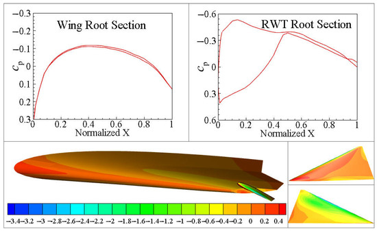
Figure 18.
The pressure coefficient at the rotation angle of .
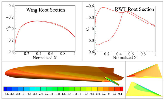
Figure 19.
The pressure coefficient at the rotation angle of .
Using the CFD/IDA coupling method and Fourier transform, the aeroelastic response results for rotation angles of and are provided in Figure A3 and Figure A4. Because the rotation angle of corresponds to the wingtip rotation frequency of 3.55 Hz, the results for are presented in Figure 13. The above results have been consolidated to produce Figure 20, which displays the vibration frequencies and damping coefficients under different dynamic pressures calculated from the MPW and MP-RWT responses for each rotation angle. In the figure, the horizontal axis is divided into three sections, corresponding to the flow dynamic pressures at rotation angles of 0°, 20°, and 25°, respectively. From the data, the derived flutter characteristics are listed in Table 4. The results show that as the wingtip rotation angle increases, the flutter velocity rises while the flutter frequency decreases.
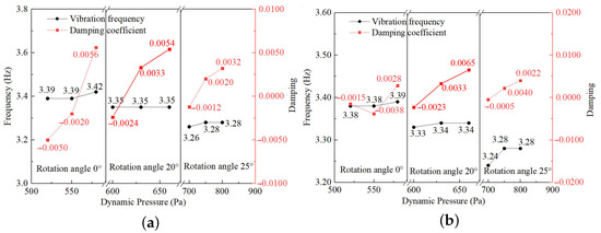
Figure 20.
Under different flow dynamic pressures, the vibration frequencies and damping coefficients for different rotation angles. (a) The results of the MPW; (b) the results of the MP-RWT.
Table 4.
Flutter characteristics of different rotation angles.
When the wingtip rotation angle is further increased to , the flutter phenomenon disappears. Figure 21 gives the aeroelastic response results when the rotation angle is . So, with an increase in flow dynamic pressure, the time response consistently remains in a convergent condition.
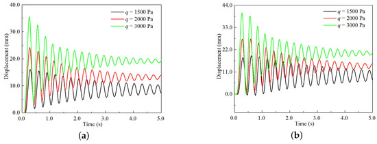
Figure 21.
Aeroelastic response results at the rotation angle of . (a) Time–response curves of the MPW; (b) time–response curves of the MP-RWT.
This subsection examines the flutter regulation of the RWT at various rotation angles. As the rotation angle increases, the critical flutter dynamic pressure rises slowly, while the flutter frequency decreases.
6.2. Experimental Results
The ground vibration test (GVT) and WTT under different wind velocities are carried out to study the aeroelastic behavior under different rotation frequencies and rotation angles of the tailless flying wing with a rotating wingtip. The modal test frequencies, acceleration response data, and auto-power spectrum are obtained through the GVT and WTT. The installation positions of the accelerometers are shown in Figure 7 and Figure 12.
6.2.1. Different Rotation Frequencies of the RWT
To control the rotation frequency of the wingtip, U-shaped springs with various widths b and thicknesses t are designed and manufactured. These springs are fabricated from 65Mn material and undergo heat treatment to achieve good strength and excellent elastic properties. Figure 5 illustrates the relevant U-shaped springs. The width of spring No. ① is 2.00 mm, and the thickness is 0.30 mm; the width of spring No. ② is 2.00 mm, and the thickness is 0.40 mm; the width of spring No. ③ is 2.00 mm, and the thickness is 0.50 mm; the width of spring No. ④ is 4.00 mm, and the thickness is 0.35 mm. During the WTT, either one or a combination of two of them is employed. Figure 22 gives the modal test results of different rotation frequencies for the RWT. All these modal test results are utilized in the WTT.
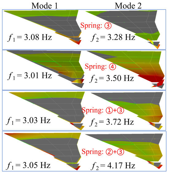
Figure 22.
The modal test results of different rotation frequencies, the number in circle is the U-shape spring’s No.
When the flow velocity reaches the flutter critical velocity, the vibration amplitude of the structure of the tailless flying wing with a rotating wingtip becomes visible to the naked eye. At this point, the acceleration response exhibits a distinct equal-amplitude phenomenon, and the single peak of the auto-power spectrum curve stabilizes. These characteristics indicate that the structure is experiencing flutter. Figure 23, Figure 24 and Figure 25 show the aeroelastic results of the WTT when the rotation frequencies of the RWT are 3.28 Hz, 3.50 Hz, and 3.72 Hz. From Table 5, the flutter velocities are 25.0 m/s, 28.0 m/s, and 38.0 m/s, respectively. Meanwhile, the flutter frequencies are 3.26 Hz, 3.41 Hz, and 3.50 Hz. This is consistent with the trend observed in the numerical simulation. As the wingtip rotation frequency increases, both the flutter critical velocity and the flutter frequency rise.
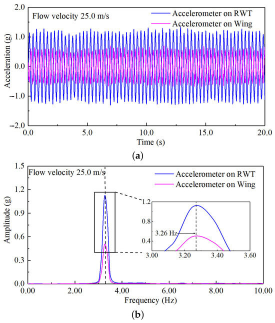
Figure 23.
The aeroelastic results of the WTT at the rotation frequency of 3.28 Hz. (a) Acceleration–response curves; (b) auto-power spectrum curves.
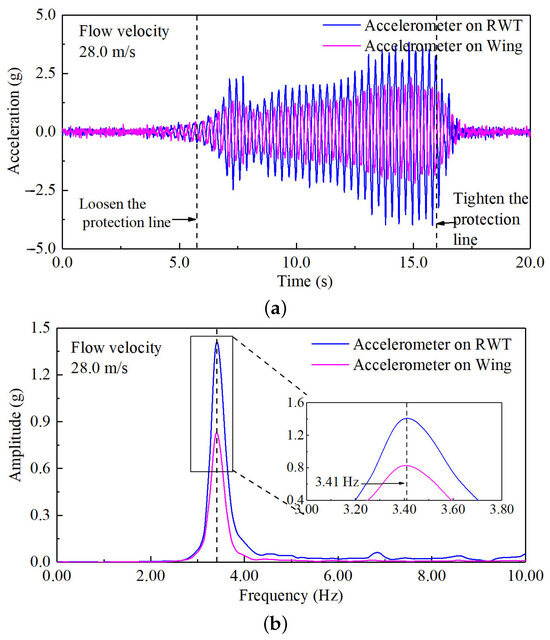
Figure 24.
The aeroelastic results of the WTT at the rotation frequency of 3.50 Hz. (a) Acceleration–response curves; (b) auto-power spectrum curves.
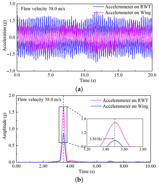
Figure 25.
The aeroelastic results of the WTT at the rotation frequency of 3.72 Hz. (a) Acceleration–response curves; (b) auto-power spectrum curves.
Table 5.
Experimental results of different rotation frequencies.
When the parallel combination of U-shaped springs No. ② and No. ③ is utilized, the structure does not exhibit flutter even when the flow velocity reaches 83% of the upper limit of the wind tunnel. To ensure the safety of the wind tunnel and the stability of the WTT, higher flow velocities were not tested. Figure 26 shows the results obtained at the highest tested flow velocity.
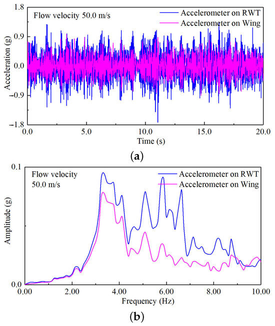
Figure 26.
The aeroelastic results of the WTT at the rotation frequency of 4.17 Hz. (a) Acceleration–response curves; (b) auto-power spectrum curves.
This subsection lists the results of the GVT and WTT. By adjusting the width and thickness of the U-shaped springs and combining them in parallel, four distinct structures with varying rotation frequencies of the RWT were obtained. Wind tunnel tests were then conducted on these structures to obtain their critical flutter speeds and frequencies. According to the experimental results, with an increase in the rotation frequency of the RWT, the critical flutter velocity and frequency increase.
6.2.2. Different Rotation Angles of the RWT
The WTT was conducted under various rotation angles, with the rotation frequency of 3.50 Hz serving as the reference condition. Figure 27 gives the modal results of different rotation angles. When the rotation angle is , the frequency of Mode 1 is 3.03 Hz and the frequency of Mode 2 is 3.50 Hz; when the rotation angle is , the frequency of Mode 1 is 3.02 Hz and the frequency of Mode 2 is 3.48 Hz; when the rotation angle is , the frequency of Mode 1 is 3.01 Hz and the frequency of Mode 2 is 3.51 Hz.
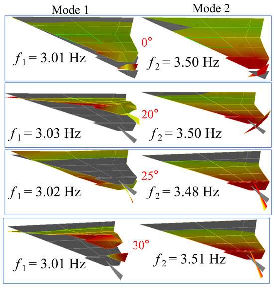
Figure 27.
The modal test results of different rotation angles.
Figure 28 and Figure 29 show the aeroelastic response results of rotation angles of and . The flutter velocities and the flutter frequencies are listed in Table 6. According to the experimental results, as the wingtip rotation angle increases, the flutter velocity rises while the flutter frequency decreases.
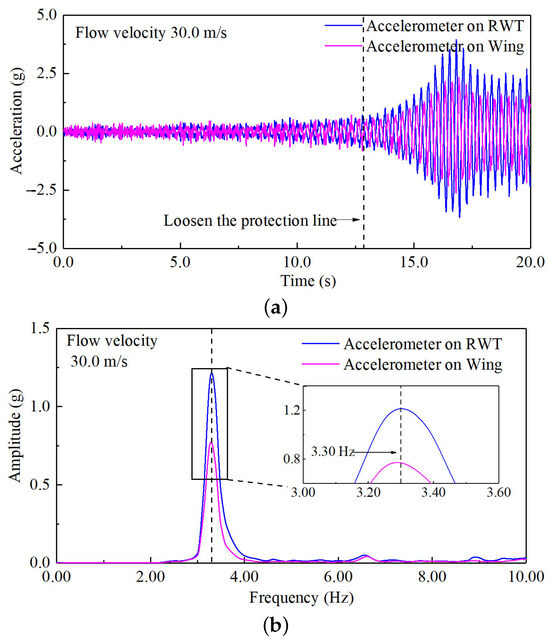
Figure 28.
The aeroelastic results of the WTT at the rotation angle of 20°. (a) Acceleration–response curves; (b) auto-power spectrum curves.
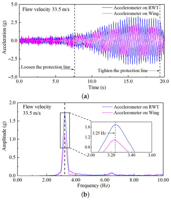
Figure 29.
The aeroelastic results of the WTT at the rotation angle of . (a) Acceleration–response curves; (b) auto-power spectrum curves.
Table 6.
Experimental results of different rotation angles.
Figure 30 gives the acceleration response curves and auto-power spectrum curves at the rotation angle of . The auto-power spectrum curve displays multiple chaotic peaks without any distinct single peak emerging. When the rotation angle of the RWT reaches , the flutter phenomenon does not occur in the structure at a flow velocity of 40.0 m/s.
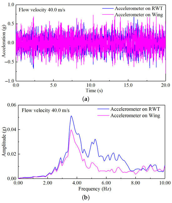
Figure 30.
The aeroelastic results of the WTT at the rotation angle of . (a) Acceleration–response curves; (b) auto-power spectrum curves.
This subsection presents the aeroelastic WTT conducted under different rotation angles of the RWT. The experimental results indicate that the flutter velocity increases as the rotation angle increases, but the flutter frequency decreases with an increase in the rotation angle.
7. Discussion
The aeroelastic behavior of the tailless flying wing with a rotating wingtip has been investigated by using both simulation and experimental methods. Aeroelastic response results have been obtained under different rotation frequencies and rotation angles. Subsequently, a comprehensive comparison of simulation and experimental results is discussed. Additionally, the vibration and flow field characteristics of the structure under the critical flutter condition are analyzed by observing the phenomena captured in both simulation and experiment.
7.1. Comprehensive Discussion of Simulation and Experimental Results
During the research process, different rotation frequencies of the RWT were determined through modal simulation analysis. To match these frequencies during testing, U-shaped springs with various widths and thicknesses were fabricated. After conducting numerous GVTs, the U-shaped spring size or combination that produced frequency results matching the simulation targets was identified. Table 7 gives the comparison of simulation and experimental modal frequencies. The simulation and experimental results for the two-order modal frequencies, which are the focus of this research, exhibit a very high degree of matching, with frequency errors being less than 5%. This indicates that the fundamental conditions of the simulation and experimental models are consistent. This provides a good foundation for subsequent aeroelastic research.
Table 7.
The comparison of simulation and experimental modal frequencies.
Table 8 shows the comparison of simulation and experimental flutter results for different rotation frequencies. The simulation and experimental results reveal that increasing the rotation frequencies of the RWT has a positive effect on enhancing the critical flutter velocity and frequency. This finding contributes to analyzing the flutter characteristics of the tailless flying wing with a rotating wingtip. The vibration characteristics of the RWT have an obvious impact on the critical flutter values. By studying these characteristics, the flutter characteristics of this aircraft configuration can be identified. This knowledge is essential for developing effective strategies to suppress flutter, thereby improving the overall stability and performance of the aircraft.
Table 8.
The comparison of simulation and experimental flutter results for different rotation frequencies.
Aeroelastic research was conducted under different rotation angles, and the basic condition is the rotation frequency of 3.55 Hz and the rotation angle of . Both simulation and experimental methods were employed to obtain the aeroelastic response results. Table 9 gives a comparison of simulation and experimental modal frequencies for different rotation angles. From the results, as the rotation angle of the RWT increases, the rotation frequency of the RWT remains essentially constant. This indicates that the rotation frequencies under different rotation angles are essentially the same, and the changes in aeroelastic characteristics are primarily due to aerodynamic factors.
Table 9.
The comparison of simulation and experimental modal frequencies for different rotation angles.
Table 10 gives a comparison of simulation and experimental flutter results for different rotation angles. The simulation and experimental results show that increasing the rotation angles of the RWT has a good effect on enhancing the critical flutter velocity. However, the flutter frequency is in a downward trend with an increase in the rotation angle. This shows that the deflection angle of the RWT has a positive effect on its flutter characteristics, and also provides a reference value for the aeroelastic design of such aircraft configurations.
Table 10.
The comparison of simulation and experimental flutter results for different rotation angles.
In summary, the detailed analysis of the rotation frequencies and angles of the aircraft under critical flutter conditions offers a comprehensive understanding of the underlying physics. This understanding is essential for designing more robust and efficient aeroelastic control systems. For instance, by manipulating the rotation frequency or modifying the rotation angle of the RWT, it can potentially delay the flutter onset or even eliminate it. The findings from this research not only highlight the significant role of wingtip rotation in the aeroelastic behavior of tailless flying wings but also pave the way for innovative approaches to flutter suppression. This work provides a solid foundation for further research and development in the field of aeroelasticity, particularly for unconventional aircraft configurations.
7.2. Discussion on Flutter Mechanism
The flutter mechanism is the internal factor for solving the structural flutter problem. It is only through a thorough grasp of the flutter mechanism of a structure that designers can uncover the underlying causes of flutter and provide valuable insights for its suppression.
Figure 31 gives the flutter vibration shapes in a cycle. During the critical flutter condition, the wing experiences elastic bending deformation due to the aerodynamic forces acting upon it. An elastic equilibrium state is then established as a result of the combined effects of aerodynamic, inertial, and elastic forces. Because of the unsteady aerodynamic forces, which are in a state of unsteady perturbation, the wing commences simple harmonic vibration around this equilibrium position. At time , both the bending deformation of the wing and the rotation deformation of the RWT reach their equilibrium position. During the interval from to , the unsteady aerodynamic forces are weaker than the elastic forces. Consequently, the wing and the RWT are restored from their equilibrium position to the peak–valley position, primarily driven by the elastic forces. At time , the deformation of the wing and RWT is nearly at the peak–valley position. Subsequently, in the to period, the unsteady aerodynamic forces surpass the elastic forces. Under the influence of the unsteady aerodynamic forces, the wing and the RWT elastic deformation move from the peak–valley position to the equilibrium position. At time , the bending deformation of the wing and the rotation deformation of the RWT attain their equilibrium position again. In the ensuing to period, the aerodynamic forces sustain action. At time , the deformation of the wing and the RWT reaches the peak-maximum position. From the time to , the elastic forces once again take precedence, and the wing and the RWT are then propelled back to the equilibrium position by the elastic forces. Under the continued influence of the aerodynamic forces, the deformation of the wing and the RWT moves from the equilibrium position back to the peak–valley and peak-maximum positions, and a new cycle of vibration commences. This cycle of vibration continues in the form of simple harmonic motion, which is characteristic of flutter.
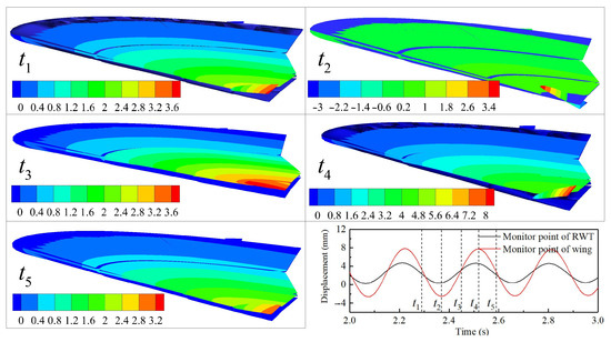
Figure 31.
The flutter vibration shapes in a cycle.
Figure 32 shows the change in aerodynamic pressure coefficient in a cycle. In the figure, the “Up” is the up surface of the RWT, and the “Down” is the down surface of the RWT. The structural vibration causes the pressure distribution on the upper and lower surfaces of the RWT to change significantly and exhibit a certain periodicity. This periodicity in the aerodynamic characteristics serves as an external factor that induces structural flutter.
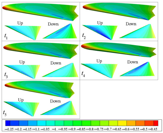
Figure 32.
The change in the pressure coefficient in a cycle.
Figure 33 depicts the phenomena captured during the WTT. These pictures are extracted from a recorded video, with each frame converted into an image. The selection of these images is performed manually to highlight representative moments; however, they do not constitute a complete cycle of vibration. In the figure, the flutter vibration shapes can be clearly observed.
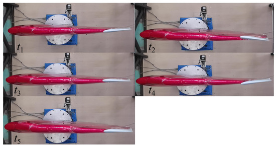
Figure 33.
The flutter vibration shapes of the WTT.
In summary, from the comprehensive analysis of the simulation cloud map and experimental phenomenon, it reveals that the flutter coupling mechanism of the tailless flying wing with a rotating wingtip is primarily established through the interaction between the RWT rotation vibration and the wing bending vibration. However, the rotation vibration of the RWT plays a more dominant role in this coupling process. In fact, it can be regarded as the main driving force behind the flutter phenomenon. Once the RWT rotation vibration is effectively disrupted or eliminated, the flutter issue ceases to exist. This finding highlights the critical importance of the RWT rotation vibration in the flutter mechanism of such aircraft configurations and suggests that targeted control or mitigation of this specific vibration mode could be a key strategy for addressing and preventing the flutter problem.
8. Conclusions
This paper has investigated the aeroelastic behavior of the tailless flying wing with a rotating wingtip. Based on the ICE configuration, an elastic model of the tailless flying wing with a rotating wingtip has been designed. The finite element models and fluid models have been established for numerical simulation analysis, and an aeroelastic model has been manufactured for wind tunnel testing. By using the simulation and experiment methods, the aeroelastic response results under different rotation frequencies and different rotation angles have been obtained. By comparing simulation and experiment results of the critical flutter state, the vibration shapes have been observed, and the flutter mechanism of such aircraft configuration has been explored. In summary, the conclusions are as follows:
- (1)
- As the rotation frequency and rotation angle increase, the critical flutter velocity continues to rise until flutter no longer occurs. But the flutter frequency increases with increasing rotation frequency and decreases with an increase in the rotation angle.
- (2)
- The flutter coupling type of the tailless flying wing with a rotating wingtip is characterized by the coupling motion of wing bending and RWT rotation. The RWT rotation motion plays a dominant role in the coupling mechanism. Disrupting the rotational vibration characteristics can raise the flutter boundary and even eliminate flutter altogether.
- (3)
- The internal factor is the stiffness characteristics of the RWT, while the external factor is the unsteady aerodynamic forces resulting from the RWT deflection. Increasing the rotation stiffness disrupts the balance between aerodynamic forces and elastic forces, thereby altering the flutter characteristics. Similarly, raising the rotation angle also changes the balance of the coupling mechanism. These two factors play an important role in the flutter phenomenon of the tailless flying wing with a rotating wingtip.
Author Contributions
Conceptualization, W.Q. and W.W.; methodology, W.W. and X.H.; software, W.W., C.H. and X.X.; validation, X.A. and Z.L.; formal analysis, W.W.; investigation, W.W., X.A., X.X. and X.H.; resources, W.W.; data curation, W.W.; writing—original draft preparation, W.W.; writing—review and editing, W.W. and X.A.; visualization, W.W. and X.X. All authors have read and agreed to the published version of the manuscript.
Funding
This research received no external funding.
Data Availability Statement
Data is contained within the article.
Conflicts of Interest
The authors declare no conflicts of interest.
Abbreviations
The following abbreviations are used in this manuscript:
| WTT | Wind tunnel test |
| GVT | Ground vibration test |
| IDA | Implicit dynamic approach |
| RWT | Rotating wingtip |
| MP-RWT | Monitor point of RWT |
| MPW | Monitor point of wing |
Appendix A. Simulation Results
The following figures present the aeroelastic response results obtained at wingtip rotation frequencies of 3.31 Hz and 3.82 Hz, and wingtip rotation angles of and .
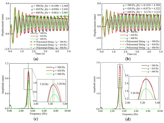
Figure A1.
Aeroelastic response results at the rotation frequency of 3.31 Hz. (a) Time–response curves of the MPW; (b) time–response curves of the MP-RWT; (c) frequency–response curves of the MPW; (d) frequency–response curves of the MP-RWT.
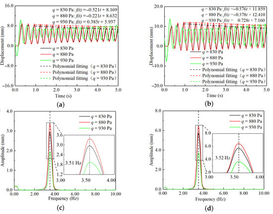
Figure A2.
Aeroelastic response results at the rotation frequency of 3.82 Hz. (a) Time–response curves of the MPW; (b) time–response curves of the MP-RWT; (c) frequency–response curves of the MPW; (d) frequency–response curves of the MP-RWT.
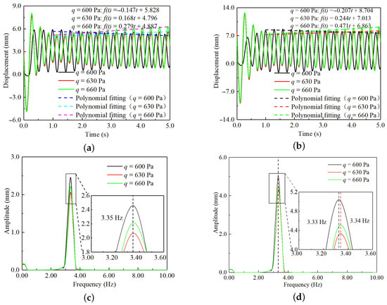
Figure A3.
Aeroelastic response results at the rotation angle of . (a) Time–response curves of the MPW; (b) time–response curves of the MP-RWT; (c) frequency–response curves of the MPW; (d) frequency–response curves of the MP-RWT.
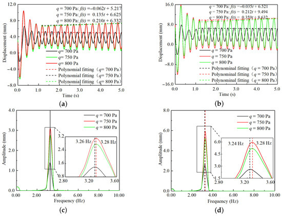
Figure A4.
Aeroelastic response results at the rotation angle of . (a) Time–response curves of the MPW; (b) time–response curves of the MP-RWT; (c) frequency–response curves of the MPW; (d) frequency–response curves of the MP-RWT.
References
- Gillard, W.; Dorsett, K. Directional Control for Tailless Aircraft Using All Moving Wing Tips. In Proceedings of the 22nd Atmospheric Flight Mechanics Conference, New Orleans, LA, USA, 11 August 1997; pp. 51–55. [Google Scholar] [CrossRef]
- Bowlus, J.; Multhopp, D.; Banda, J. Challenges and Opportunities in Tailless Aircraft Stability and Control. In Proceedings of the Guidance, Navigation, and Control Conference, New Orleans, LA, USA, 11–13 August 1977; pp. 1713–1718. [Google Scholar] [CrossRef]
- Niestroy, M.A.; Dorsett, K.M.; Markstein, K. A Tailless Fighter Aircraft Model for Control-Related Research and Development. In Proceedings of the AIAA Modeling and Simulation Technologies Conference, Grapevine, TX, USA, 9–13 January 2017; pp. 1–17. [Google Scholar] [CrossRef]
- Williams, D.R.; Seidel, J.; Osteroos, R.; McLaughlin, T.E. NATO AVT-239 Task Group: Flight Control Derivatives using Active Flow Control Effectors on the ICE/SACCON UAS Model. In Proceedings of the AIAA Scitech 2019 Forum, San Diego, CA, USA, 7–11 January 2019; pp. 1–9. [Google Scholar] [CrossRef]
- Niestroy, M.A.; Williams, D.R.; Seidel, J. ATO AVT-239 Task Group: Active Flow Control Simulation of the Tailless ICE Aircraft. In Proceedings of the AIAA Scitech 2019 Forum, San Diego, CA, USA, 7–11 January 2019; pp. 1–14. [Google Scholar] [CrossRef]
- Maines, B.H.; Miller, D.N. NATO AVT-239 Task Group: Air Vehicle Integration Considerations for Active Flow Control on a Future UAS. In Proceedings of the AIAA Scitech 2019 Forum, San Diego, CA, USA, 7–11 January 2019; pp. 1–7. [Google Scholar] [CrossRef]
- Niestroy, M.A. NATO AVT-350 Task Group: Active Flow Control Simulation of the Tailless ICE Aircraft; Landing Results. In Proceedings of the AIAA Scitech 2025 Forum, Orlando, FL, USA, 6–10 January 2025; pp. 1–13. [Google Scholar] [CrossRef]
- Forster, M.; Renals, Y.; Warsop, C. NATO AVT-350 Task Group: Assessment of Supercritical Coanda Based Circulation Control on the ICE Planform. In Proceedings of the AIAA Scitech 2025 Forum, Orlando, FL, USA, 6–10 January 2025; pp. 1–8. [Google Scholar] [CrossRef]
- Yu, C.; Wang, X.; Chen, P.; Su, X. Study of Control Characteristics for All Moving Wing Tips in Delta Wing Tailless Configuration. Acta Aeronaut. Astronaut. Sin. 2012, 33, 1975–1983. [Google Scholar]
- Wang, Z.; Hu, L.; Fei, W.; Zhou, D.; Yang, D.; Ma, C.; Gong, Z.; Wu, J.; Zhang, C.; Yang, Y. High-Performance Attitude Control Design of Supersonic Tailless Aircraft: A Cascaded Disturbance Rejection Approach. Aerospace 2023, 10, 198. [Google Scholar] [CrossRef]
- Yuan, C.; Ma, D.; Jia, Y.; Yang, M.; Zhang, L. Numerical Analysis of Pitch-break and All Moving Wingtip Aileron of Lambda Wing Configuration. Aerosp. Sci. Technol. 2023, 141, 108508. [Google Scholar] [CrossRef]
- Zuo, L.; Wang, J. Experimental Study of the Effect of AMT on Aerodynamic Performance of Tailless Flying Wing Aircraft. Acta Aerodyn. Sin. 2010, 28, 132–137. [Google Scholar]
- Nikolic, V.R. Movable Tip Strakes and Wing Aerodynamics. J. Aircr. 2005, 42, 1418–1426. [Google Scholar] [CrossRef]
- Nikolic, V.R. Optimal Movable Wing Tip Strake. J. Aircr. 2011, 48, 335–341. [Google Scholar] [CrossRef]
- Chauhan, S.S.; Martins, J.R.R.A. RANS-Based Aerodynamic Shape Optimization of a Wing with a Propeller in Front of the Wingtip. Aerospace 2024, 11, 512. [Google Scholar] [CrossRef]
- Wang, Z.; Pan, C.; Cheng, Z. Assessment of Prevalent Vortex-center Detection Criteria for the Compensation of Wandering Motion of Wingtip Vortices. Aerosp. Sci. Technol. 2025, 160, 110069. [Google Scholar] [CrossRef]
- Gao, Z.; Yue, H.; Shao, X.; Zhang, S.; Zeng, L.; Pan, D. Aerodynamic Interaction Mechanisms in Typical Wingtip-mounted Tractor Propeller Configurations. Phys. Fluids 2024, 36, 125126. [Google Scholar] [CrossRef]
- Zaccara, M.; Paolillo, G.; Cafiero, G.; Astarita, T.; Iuso, G.; Cardone, G.; Greco, C.S. Near Field Evolution of Wingtip Vortices under Synthetic-jet Based Control. Aerosp. Sci. Technol. 2024, 148, 109068. [Google Scholar] [CrossRef]
- Schröder, D.; Leweke, T.; Hörnschemeyer, R.; Stumpf, E. Generation of a Wingtip Vortex Pair Using a Pressure-side Fin. Aerosp. Sci. Technol. 2022, 130, 107860. [Google Scholar] [CrossRef]
- Wang, W.; Qian, W.; He, X.; Ai, X.; Chen, Z. Flutter Regularity of Flying Wing Configuration with All-Moving Wing Tip. Phys. Gases 2023, 8, 65–74. [Google Scholar] [CrossRef]
- Wang, W.; Qian, W.; Ai, X. Aeroelastic Divergence and Flutter Analysis of a Wing with All Moving Wing Tip. In Proceedings of the 2024 ICAS, Florence, Italy, 8–12 September 2024; pp. 1–5. [Google Scholar]
- Zhou, D.; Lu, W.; Wu, J.; Guo, T.; Lv, B.; Guo, H.; Xia, H. Numerical Simulation of Folding Tail Aeroelasticity Based on the CFD/CSD Coupling Method. Vibration 2024, 7, 705–721. [Google Scholar] [CrossRef]
- Zou, Z.; Xie, C.; An, C.; Yang, L.; Ni, Z. Development of Accelerated CFD/CSD Coupling Nonlinear Static Aeroelastic Algorithm Using Vortex Lattice Method. AIAA J. 2025, 63, 2568–2573. [Google Scholar] [CrossRef]
- Wang, S.; Cheng, Q. CFD-CSD Method for Rotor Aeroelastic Analysis with Free Wake Model. Aircr. Eng. 2023, 95, 132–144. [Google Scholar] [CrossRef]
- Wang, W.; Qian, W.; Chen, Z.; Ai, X. An Aeroelastic Solution Method Using an Implicit Dynamic Approach. Aerospace 2025, 12, 546. [Google Scholar] [CrossRef]
- Hou, G.; Wang, J.; Layton, A. Numerical Methods for Fluid-Structure Interaction—A Review. Commun. Comput. Phys. 2012, 12, 337–377. [Google Scholar] [CrossRef]
- Maliska, C.R. Fundamentals of Computational Fluid Dynamics: The Finite Volume Method; Springer International Publishing AG: Cham, Switzerland, 2023; pp. 15–31. [Google Scholar] [CrossRef]
- Moioli, M.; Breitsamter, C.; Sørensen-Libik, K. Spalart-Allmaras Turbulence Model Conditioning for Leading-Edge Vortex Flows. In Advanced Aircraft Understanding Via the Virtual Aircraft Model; Heinrich, R., Ed.; Springer International Publishing AG: Cham, Switzerland, 2024; pp. 129–135. [Google Scholar] [CrossRef]
- Balakrishnan, A. Aeroelasticity: The Continuum Theory; Springer: New York, NY, USA, 2012; pp. 269–323. [Google Scholar] [CrossRef]
- Sinha, R. Advanced Newtonian Rigid Dynamics; Springer: Singapore, 2023; pp. 127–248. [Google Scholar] [CrossRef]
- Benacquista, M.J.; Romano, J.D. Classical Mechanics; Springer International Publishing AG: Cham, Switzerland, 2018; pp. 49–51. [Google Scholar] [CrossRef]
- Hilber, H.M.; Hughes, T.J.R.; Taylor, R.L. Improved Numerical Dissipation for Time Integration Algorithms in Structural Dynamics. Earthq. Eng. Struct. Dyn. 1977, 5, 283–292. [Google Scholar] [CrossRef]
- Liu, X.; Yu, J.; Kurihara, T.; Wu, C.; Zhang, H. A Complex Neural Network Model by Hilbert Transform. Pattern Recognit. Lett. 2024, 186, 113–118. [Google Scholar] [CrossRef]
- Stam, N.; Visser, C.C. Adaptive Dynamic Incremental Nonlinear Control Allocation for Aircraft with Innovative Control Effectors. In Proceedings of the AIAA Scitech 2025 Forum, Orlando, FL, USA, 6–10 January 2025; p. 10. [Google Scholar] [CrossRef]
Disclaimer/Publisher’s Note: The statements, opinions and data contained in all publications are solely those of the individual author(s) and contributor(s) and not of MDPI and/or the editor(s). MDPI and/or the editor(s) disclaim responsibility for any injury to people or property resulting from any ideas, methods, instructions or products referred to in the content. |
© 2025 by the authors. Licensee MDPI, Basel, Switzerland. This article is an open access article distributed under the terms and conditions of the Creative Commons Attribution (CC BY) license (https://creativecommons.org/licenses/by/4.0/).