Review

Vapor Compression Refrigeration System for Aircrafts: Current Status, Large-Temperature-Range Challenges and Emerging Auto-Cascade Refrigeration Technologies

1
School of Energy and Environmental Engineering, University of Science and Technology Beijing, Beijing 100083, China
2
School of Aeronautic Science and Engineering, Beihang University, Beijing 100191, China
3
Avic Jincheng Nanjing Engineering Institute of Aircraft System, Nanjing 211106, China
4
Aviation Key Laboratory of Science and Technology on Aero Electromechanical System Integration, Nanjing 211106, China
*
Author to whom correspondence should be addressed.
Aerospace 2025, 12(8), 681; https://doi.org/10.3390/aerospace12080681
Submission received: 21 June 2025 / Revised: 28 July 2025 / Accepted: 28 July 2025 / Published: 30 July 2025
(This article belongs to the Special Issue Aerospace Human–Machine and Environmental Control Engineering)

Abstract

Modern aircraft increasingly utilizes highly integrated electronic equipment, driving continuously increasing heat dissipation demands. Vapor compression refrigeration systems demonstrate stronger alignment with future aircraft thermal management trends, leveraging their superior volumetric cooling capacity, high energy efficiency, and independence from engine bleed air. This paper reviews global research progress on aircraft vapor compression refrigeration systems, covering performance optimization, dynamic characteristics, control strategies, fault detection, and international development histories and typical applications. Analysis identifies emerging challenges under large-temperature-range cooling requirements, with comparative assessment establishing zeotropic mixture auto-cascade vapor compression refrigeration systems as the optimal forward-looking solution. Finally, recognizing current research gaps, we propose future research directions for onboard auto-cascade vapor compression refrigeration systems: optimizing refrigerant mixtures for flight conditions, achieving efficient gas-liquid separation during variable overloads and attitude conditions, and developing model predictive control with intelligent optimization to ensure reliability.

1. Introduction

The ongoing modernization of airborne weapon systems and proliferation of highly integrated avionics have imposed increasingly stringent requirements on thermal management system (TMS) performance in aircraft. Concurrently, thermal loads generated by propulsion systems, electrical power systems, and hydraulic systems continue to escalate. Furthermore, the prevailing trend toward integrated and compact airframe design confines multiple heat sources within restricted spatial envelopes. Consequently, thermal management has emerged as a pivotal core technology for modern aircraft [1,2,3,4].
A distinctive characteristic of airborne TMSs, compared to ground-based counterparts, lies in their unique gravitational environment. During flight, acceleration overload (G-load) and aircraft attitude vary continuously, where G-load is defined as the ratio of experienced load to normal gravity (1 G). To meet demanding maneuver requirements, both magnitude and direction of G-load undergo wide-range variations. For instance, carrier-based aircraft sustain horizontal G-loads of 4–6 G during landing deceleration, while fighter jets experience vertical G-loads reaching 6–7 G in specific training maneuvers [5]. Microgravity conditions during rapid descent also constitute a G-load state, specifically vertical G-load < 1 G. Regarding aircraft attitude, pitch, yaw, and roll angles change dynamically throughout flight [6]. The combined effects of G-load and attitude can be equivalently represented as an instantaneously variable gravitational effect, termed “time-varying gravity” (VG). This concept encompasses two essential aspects: gravity differs from conventional gravity, and it varies temporally. The VG impact on TMS manifests in two dimensions: G-load variations induce instantaneous changes in both gravitational magnitude and direction, whereas attitude alterations exclusively affect directional orientation.
Effective thermal management in aircraft necessitates systematic coordination of three core processes: heat acquisition from sources, heat transport via coolant circuits, and heat rejection to terminal sink [7,8]. As terminal sink temperature is often higher than heat source temperature, refrigeration cycle is necessary because active (with forced pump circulation) or passive (using two-phase heat conductors) systems can only transfer heat to lower temperature heat sink [9,10].
Consequently, the overall efficacy of Aircraft TMS is constrained by structural optimization of refrigeration systems and thermodynamic cycle efficiency. The implementation of high-efficiency refrigeration cycles directly governs precise thermal load regulation capabilities. Theoretically, the most effective refrigeration cycle is the Carnot refrigeration cycle (reverse Carnot cycle) [11], which assumes isentropic compression and expansion, as well as isothermal condensation and evaporation, achieving the highest refrigeration efficiency. However, in practical engineering, fully realizing the reverse Carnot cycle faces technical bottlenecks: for example, isothermal compression requires infinitely slow heat exchange, while isentropic expansion relies on complex and inefficient expanders. Therefore, the vapor compression refrigeration cycle, designed based on this theoretical prototype, has become the most widely used technical solution today, with a coefficient of performance (COP) up to 3~5 times that of traditional air cycle systems (ACS) [12,13]. The schematic diagram of a single-stage vapor compression system (VCS) is shown in Figure 1, and the specific process of the refrigeration cycle is as follows: First, the working fluid enters the compressor in a superheated vapor state at low pressure and low temperature, and is compressed into high-temperature and high-pressure gas in an extremely short time (Figure 1b, Process 1–2). Then, the high-temperature and high-pressure gas enters the condenser, where it releases heat to the environment under near-isothermal conditions and gradually condenses into high-pressure liquid (Figure 1b, Process 2–3). Next, the high-pressure liquid working fluid flows through the expansion valve, achieving pressure and temperature reduction through adiabatic throttling (Figure 1b, Process 3–4). Subsequently, in the evaporator, the working fluid absorbs heat from the medium to be cooled, completing vaporization through isothermal evaporation (approximately isothermal expansion similar to the reverse Carnot cycle), and exits in the form of superheated vapor at low pressure and low temperature (Figure 1b, Process 4–1), completing the cycle and returning to the initial state [14,15,16,17]. Therefore, vapor compression refrigeration technology has become a key development direction in modern aircraft thermal management due to its capacity and energy efficiency advantages brought by the latent heat of the working fluid phase change. Compared to traditional ACSs, this technology eliminates engine bleed air requirements, significantly reduces fuel compensation losses, and enhances aircraft maneuverability. It has now been successfully applied to multiple advanced fighter aircraft globally [18,19,20].
Table 1 summarizes and compares the differences between relevant literature and this paper. Existing literature provides a comprehensive description of VCSs in fields such as building environmental control and automotive thermal management, covering multiple technical aspects such as system optimization, energy efficiency improvement, and the application of new refrigerants. In contrast, review studies targeting aircraft applications are obviously insufficient, particularly those focusing on the design and performance optimization of aircraft VCSs for large-temperature-range requirements. Therefore, this paper reviews the latest advancements and current applications of aircraft vapor compression refrigeration technology in recent years, identifies the shortcomings of existing research, and outlines future development directions, providing a reference for scholars and researchers in related fields.

2. Research Progress

2.1. Experimental Research

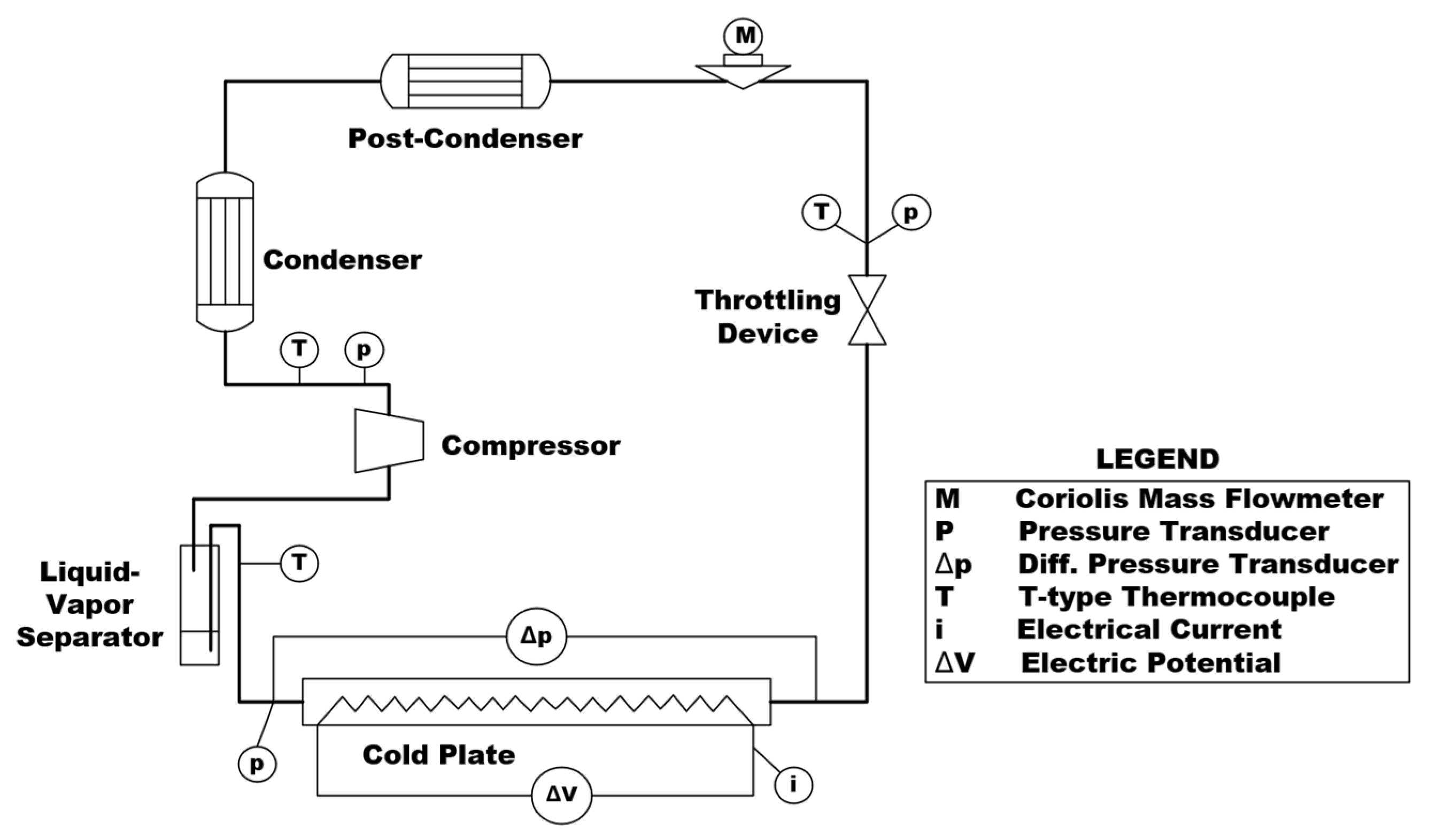
VCSs are an effective means to address the large heat dissipation requirements of some onboard electronic devices [27]. Currently, to cope with the increasing thermal load of avionics, VCSs need to achieve efficient cooling through component lightweighting and system integration, for example, the device proposed by Dooley et al. [28,29] for the integrated power and thermal management system, which optimizes volume by reducing the number of compressor components. In recent years, scholars have made significant breakthroughs in device-level vapor compression refrigeration technology through system optimization design and key component innovation, providing effective solutions for the growing heat dissipation demands of avionics. Qi et al. [30] established a VCS for aviation electronic devices and experimentally evaluated its performance and dynamic behavior. The working fluid was R134a, with a cold source temperature of 16–46 °C and a heat flux of 50–150 kW/m2. Under varying cold-source temperatures, the heating wall temperature and pressure drop in fixed-speed pump mode range from 33.7 to 60 °C and 78.0 to 119.6 kPa, respectively. In variable-speed pump mode, these parameters vary between 34.1–60 °C and 59.6–124.6 kPa. Compared to low-temperature startup, high-temperature startup resulted in lower wall temperatures and higher pressure drops. When the heat load jumped, regardless of the pumping mode, the wall temperature and pressure drop first rose before stabilizing. Mancin et al. [31] further expanded the performance boundaries of the system by experimentally studying a miniaturized VCS for onboard electronic device thermal management, as shown in Figure 2. The refrigerant was R134a, with a pressure ratio of 1.54–3.75, and the system achieved a cooling capacity of 37–374 W and a COP of 1.04–5.80, indicating that by optimizing cycle parameters, the energy efficiency of device-level systems has approached that of traditional large-scale refrigeration systems. In terms of system structural design, Erkinaci et al. [32] designed a compact VCS suitable for device-level applications and evaluated its performance through experiments and simulations. The working fluid was R134a, weighing 2.8 kg and measuring 600 mm × 400 mm × 250 mm, and it included a miniature refrigeration compressor. The system achieved a cooling capacity of 623 W at a 50 °C ambient temperature, with COP of 2.7, while maintaining the device temperature below or near the ambient temperature. This is an excellent solution for component-level thermal management of onboard electronic devices in harsh thermal environments, fully demonstrating the application potential of vapor compression refrigeration technology in extreme thermal conditions. Regarding innovations in critical components, the Lightweight Miniature Wankel Compressor developed by Zhi et al. [33] significantly advances device-level implementation of vapor compression refrigeration technology. The optimal charge of 220 g and a COP of 2.8 indicate that by improving the compressor configuration, the refrigerant demand can be significantly reduced. Additionally, after 600 h of testing, the compressor operated stably, demonstrating its reliability for long-duration missions and making it suitable for long-term use in aircraft.
Regarding the issue of refrigerant charge in system cooling in dynamic flight environments, Gao et al. [34] constructed an onboard quasi-two-stage vapor compression refrigeration experimental system, analyzed the influence patterns of refrigerant charge, high and low temperature onboard conditions, and relative charging rate on the system’s refrigeration performance. They determined the optimal refrigerant charging rate for the system and demonstrated that this value is universal across different onboard conditions and relative charging rates. Puntel et al. [35] addressed the control and management of refrigerant charge in onboard VCSs by developing a real-time measurement method for refrigerant charge and proposing a series of efficiency optimization techniques at the system’s dynamic operating points. Byrd et al. [36] discussed methods for determining appropriate refrigerant charge. To ensure safe and efficient operation of the VCS, they charged the system with refrigerant, analyzed performance variation with charge under static/dynamic conditions, and explained the impact of charge levels on VCSs.
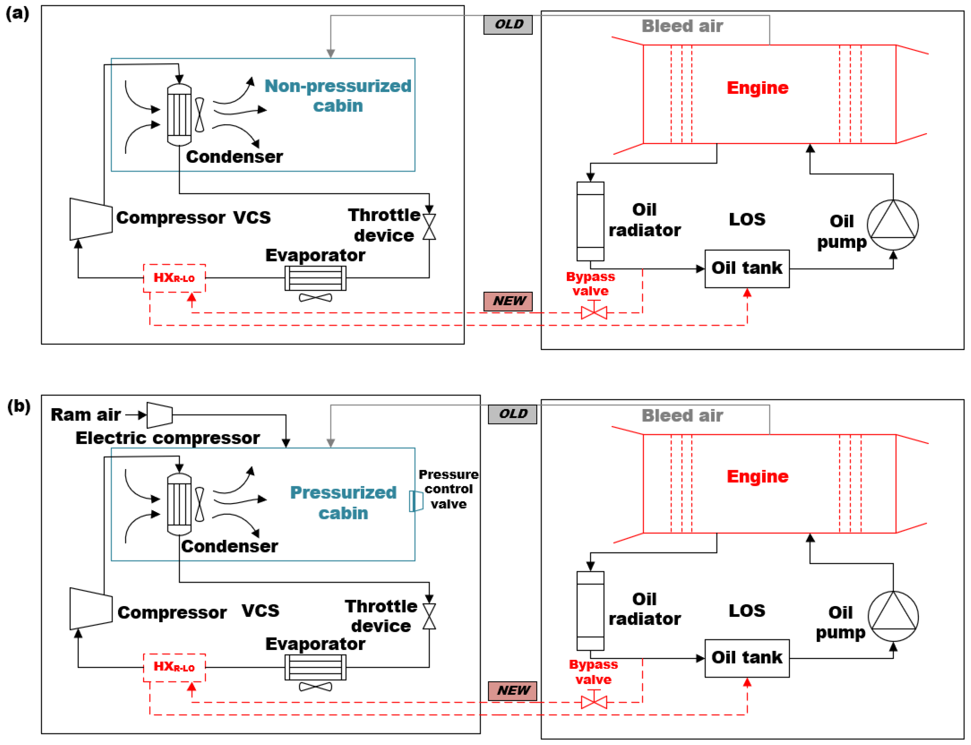
To improve the overall performance of the system, numerous scholars have conducted a series of studies from perspectives such as operating parameters, system configuration, and system components, gradually establishing a technical system adapted to the thermal management needs of aircraft. In the aspect of operating parameter optimization, Kang et al. [37] established an ACS and a VCS using R236fa as the refrigerant. By changing the compressor speed, evaporator air-side flow rate, condenser air-side flow rate, and temperature, they measured the system’s operating characteristics and revealed the impact of various system parameters on system performance. Wang et al. [38] focused on an onboard VCS based on a liquid-cooled evaporator as the research subject, finding that the impact of the cold source antifreeze inlet temperature on system performance was significantly higher than that of the cold source flow rate. These two studies collectively demonstrate that the dynamic response between system performance and various operating parameters exhibits a significant nonlinear characteristic, meaning that system performance can be improved by optimizing one or more key operating parameters. In terms of system configuration innovation, Fan et al. [39] constructed a ground steady-state test bench for a closed-loop environmental control system (ECS) consisting of two subsystems: vapor compression refrigeration and cooling fluid circulation. They conducted ground steady-state tests on key components such as the evaporator and condenser, and completed research on the heat transfer performance of the evaporator and condenser, validating and refining the established simulation model. Meanwhile, Sung et al. [40] designed a highly unique VCS that stacked a vane-type compressor, a film-type condenser, an expansion nozzle, and a microchannel evaporator. Based on this system, they proposed an empirical model and a robust control system [41], showcasing the high refrigeration capacity and excellent temperature tracking performance of the VCS. In addition, deep coupling design also reflects innovation in system configuration. For example, a system that couples a vapor compression system and a lubrication system (LOVCS), as shown in Figure 3, achieves coordinated regulation of waste heat recovery and cabin heating; the coupling of a compact loop heat pipe and a micro VCS demonstrates its potential and feasibility in typical onboard scenarios [42,43]; and the coupling of traditional compressed air architecture and vapor cycle loop addresses the increasing thermal load of avionics equipment compartments [37,44]. These system-level experiments collectively reveal the significant advantages of deep coupling architecture in energy efficiency improvement, operational robustness, and multi-physics field coordination. At the level of improving system components, Yang et al. [45] conducted performance calculations of the quasi-secondary compression vapor compression refrigeration theoretical cycle and product system performance tests, finding that compared to single-stage compression systems, this system can significantly reduce compressor speed and exhaust temperature while maintaining the same refrigeration power, improving compressor service life and reliability, and substantially reducing compressor power consumption under the same power, thereby reducing fuel consumption for aircraft ECSs. Yang et al. [46] adopted a two-stage parallel flow core stack technology for the condenser and implemented an optimization scheme with a two-stage core series structure, greatly reducing the mass and volume of the condenser while meeting the heat exchange performance requirements. The VCS, already applied to worldwide aircraft, has passed experimental and flight test verification.
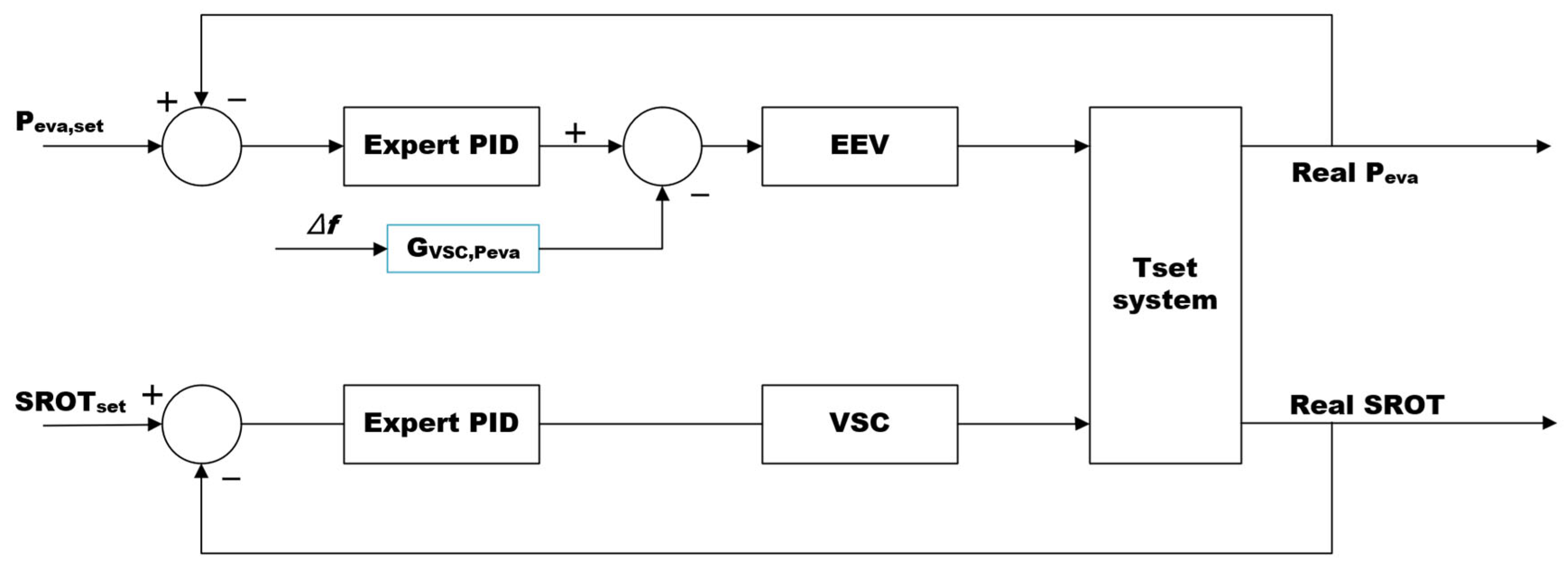
To optimize the control performance of the system, Wen et al. [47] compared methods of controlling the evaporating pressure of the VCS by adjusting the opening degree of the electronic expansion valve (EEV) and methods of controlling the superheat degree at the evaporator outlet. It was found that under severe environmental changes, the improved control strategy could achieve more stable control effects. This control strategy is shown in Figure 4, where the evaporating pressure is maintained at 420 ± 16 kPa, and the evaporating temperature can be kept at 20 ± 2 °C. Michalak et al. [48] proposed an alternating cycle-based strategy, modulating the compressor to control the saturation suction temperature and directly controlling the evaporator heat load outlet temperature by adjusting the expansion valve. Compared to controlling superheat and cooling capacity regulation, it achieved better control characteristics and COP. Byrd et al. [49] developed a two-phase thermal energy management system, integrating dual evaporators and EEVs, and developed a dynamic optimization control strategy. Experimental validation confirmed its stability in handling transient loads (thermal load fluctuations of 47–75%) in multi-evaporator VCS, achieving a COP of 2.39 and a system time constant of 13 s.
Fault detection of the system is key to ensuring its safe operation. Sun et al. [50] experimentally studied the problem of refrigerant charge faults in enhanced vapor injection VCSs with flash tanks on civil aircrafts, obtaining a hybrid segmented fault detection and diagnosis model combining three models for refrigerant charge faults in enhanced vapor injection onboard VCS with flash tanks. Gao et al. [34] built an onboard two-stage compression VCS based on technical specifications for onboard refrigeration systems, and conducted modal, random vibration, and thermal stress analysis of connected pipes based on ANSYS to determine potential failure points, comprehensively verifying the structural reliability of the system under onboard dynamic and static loads. Sun et al. [51] obtained the main failure modes affecting the safety and reliability of onboard VCSs through failure mode and effects analysis (FMEA). Based on this analysis, they experimentally simulated nine gradual faults that are relatively harmful to VCSs and developed an onboard VCS fault diagnosis reasoning model: Genetic Algorithm-Principal Component Analysis-Backpropagation (GA-PCA-BP). Liu et al. [52] established a fault diagnosis model for airborne VCSs based on the Particle Swarm Optimization-Support Vector Machine algorithm (PSO-SVM). They utilized the GUI module in MATLAB to design a visual interface for the model, developing software that enables training and testing of the fault diagnosis model, as well as diagnosing user-input system operational data. The reliability and accuracy of the software were validated through multiple sets of operational data. Yang et al. [53] took a specific type of onboard VCS as the research object, using model-based systems engineering (MBSE) methods to explain the causes of compressor start-up faults, proposing optimization and improvement measures for single-line communication based on this, and conducting bench tests to verify the effectiveness of the optimization and improvement measures. Finally, they validated through onboard flight tests. Against the backdrop of increasing requirements for power grid quality in helicopter electronic equipment, this research provides guidance for the design and application of VCSs on helicopters in the future.
In summary, facing continuously increasing performance requirements for aircraft TMSs, researchers have made persistent efforts from various research perspectives to improve vapor compression refrigeration technology for aircraft through experimental studies. Table 2 systematically summarizes these key research contents and their primary results.

2.2. Simulation Research

Many scholars establish corresponding models and conduct steady-state simulations based on specific flight missions or particular airborne environments, and further explore the relationships between system parameters or the possibilities of performance optimization. Scholars in the Matlab/Simulink simulation environment established various evaporative cycle cooling models, such as the airborne evaporative cycle cooling system model with liquid-to-liquid heat exchange, the megawatt-class aircraft turbo-electric propulsion system thermal management model, and the military aircraft ECS simulation model, etc. [54,55,56,57], analyzing the impact of various system parameters on the TMS performance of aircraft, and found that evaporating pressure, condensing pressure, and compressor speed are important factors affecting the system’s cooling capacity and COP. Based on the results, the system was optimized, among which the analysis results for the thermal management of the megawatt-class aircraft turbo-electric propulsion system were ultimately applied to the integrated thermal-electric cooperative design of the blended-wing-body aircraft. Wang et al. [58] studied a quasi-two-stage compression cycle system with an economizer, performing steady-state calculations with the evaporative cycle prototype requirements of a certain type of civil aircraft as input conditions, and found that the fuel compensation of the throttling system before the flash chamber is better than that of the single-machine system; under more severe operating conditions, its performance is significantly improved compared to the single-stage system. Peng et al. [59] established corresponding refrigeration system models based on the system and component parameters of a helicopter air conditioning system in VapCycr software, and found that under the same operating conditions, the COP values of R134a and R1234yf are invisibly different and are the highest, followed by R407C, while R32 and R410A have similar results with the lowest COP values; the cooling capacity from highest to lowest is R32, R410A, R407C, R134a, and R1234fa. Gupta et al. [60] simulated an evaporative cycle cooling system of a two-seat trainer aircraft, with the system using R134a as the refrigerant, achieving an average cabin temperature of 26 °C and a relative humidity of 50% and actual COP of 2.26 under environmental temperature conditions of 40 °C and flight Mach number of 0.4. Hu et al. [61] developed a steady-state simulation mathematical model to predict the performance of the evaporative cycle cooling cycle auxiliary system of civil aircraft, and experimentally verified the proposed simulation model, with the system’s cooling capacity, temperature, and pressure deviations within ±8%, ±8%, and ±10%, respectively. Ablanque et al. [62] developed a Modelica/Dymola library for simulating VCS with numerical stability, computational accuracy, and computational efficiency as the guiding principles, and integrated it into a representative aircraft ECS to replicate typical commercial aircraft flight missions. These simulation simulations are used to optimize system performance by analyzing the impact of various system parameters on system performance. In addition, some research uses simulation simulations to design and analyze new system architectures to improve system performance, such as closed-loop vapor cycles and hybrid systems [63]. Modern aircraft, such as Airbus A350, A380, and Boeing 787, all adopt this hybrid architecture.
Due to the complex and variable nature of the airborne environment, any dynamic parameter point of the evaporative cooling system determines whether the system can operate. Many scholars have conducted relevant research on the dynamic characteristics of the system. Peng et al. [64] utilized AMESim to establish models of the helicopter evaporative cooling system and the cabin, with both condensation and evaporation sides involving air heat exchange, obtaining the dynamic changes in cooling capacity and COP of the evaporative cooling system under ground and flight conditions. The maximum temperature span between the ambient temperature and cabin temperature is 23 °C, with the temperature span of condensation and evaporation temperatures not exceeding approximately 50 °C. Long et al. [65] analyzed the coupling relationships of various parameters in the airborne evaporative cooling system and established steady-state models of the compressor and expansion valve using lumped parameter methods, as well as dynamic models of the evaporator and condenser with both sides involving liquid heat exchange using the moving boundary method, thereby obtaining a system model with R142b as the working fluid and verifying the simulation results through experiments. The temperature span of condensation and evaporation is approximately 45 °C. Zhu et al. [66] established a helicopter onboard VCS model using the AMESim platform, where both the condenser and evaporator sides exchanged heat with air. They investigated the system’s dynamic characteristics under high-temperature and high-humidity environments and evaluated the impact of such conditions on system performance. The maximum temperature difference between the ambient temperature and the cabin temperature was 27 °C, while the corresponding temperature difference between the condensation temperature and evaporation temperature remained below approximately 55 °C. Wang et al. [67] established a quasi-two-stage compression evaporative cooling system model based on Matlab/Simulink and obtained the dynamic parameters of the airborne quasi-two-stage evaporative cooling cycle under various parameter changes such as compressor speed, heat sink, and cooling load. Li et al. [68] obtained the dynamic response characteristics of the system by discretizing the model equations using the control volume method in the Matlab/Simulink system simulation environment. The simulation results show that when the compressor speed, expansion valve opening, and refrigerant flow undergo step changes, the dynamic response characteristics of various thermal performance parameters of the evaporative cooling system are different. Ablanque et al. [69] proposed a Modelica library for simulating vapor compression cycles under steady and transient conditions, which offers advantages such as high computational efficiency, good prediction accuracy, and numerical stability. Liu et al. [70] proposed a dynamic simulation method based on a vapor cycle response surface model for aircraft thermal management. By constructing a second-order response surface model through Monte Carlo experiments, they simplified the thermodynamic calculations of the VCS and analyzed the coupling relationships of thermal parameters and fuel/ram air flow optimization strategies for the F-22 during different flight stages.
To discuss the impact of variable gravity environments in aircraft on the system and corresponding strategies, Dexter et al. [71] discussed the centrifuge built by the Armstrong Laboratory for simulating flight dynamic environments and used it to simulate various flight loads, researching the component design of the evaporative cooling system in variable gravity environments. Watts et al. [72] further used the aforementioned centrifuge to simulate the dynamic environment during flight and tested the onboard evaporative cooling system, with the results indicating that the system can withstand up to 4Gx, 4Gy, 9Gz gravitational tests. A reasonable numerical control system is the condition for ensuring its stable operation under variable gravity fields.
To address control issues in complex dynamic airborne environments, Zhou et al. [73] established a simulation model of the airborne VCS. They numerically studied the coupled response of system parameters to changes in internal component parameters and external disturbance variables, as well as the variation patterns of the COP. This provided a theoretical foundation for research on control methods under multi-disturbance conditions. They also proposed a decoupling control method based on a backpropagation (BP) neural network, which effectively improved control performance. The principle is shown in Figure 5. Li et al. [74] established a dynamic simulation model of the auxiliary cooling system for civil aircraft and conducted dynamic simulation calculations during the cruise phase. The results showed a condensing temperature of 28.39–31.33 °C and an evaporating temperature of −17.93 to −10.71 °C, meeting the design range of 30 ± 5 °C and −15 ± 5 °C. This indicates good consistency between the model and the actual system characteristics. Based on the developed model, control optimization was performed to eliminate temperature fluctuations. After optimization, the maximum temperature deviation of the system after startup decreased from 0.4004 K to 0.0019 K, demonstrating the feasibility of optimizing control methods based on the developed dynamic simulation model. Adelia et al. [75] modeled the VCS for reconnaissance aircraft. By adjusting the compressor speed to influence system capacity, they adapted it to the heat flux of 10 kW–70 kW required by reconnaissance aircraft systems. On this basis, they designed an optimized control strategy for the compressor. Daniel et al. [76] developed a linear model predictive controller to address temperature regulation and disturbance suppression issues of the airborne VCS under large transient heat loads. This controller successfully regulated multiple load temperatures, handled different load sensitivities and constraints, and could take predictive measures to suppress large disturbances. Zhao et al. [77,78] established a model of the airborne VCS for a specific aircraft flight profile using AMESim, and performed system performance simulation with the superheat degree at the condenser outlet and the subcooling degree at the evaporator outlet as target functions. They developed a dual-control strategy that meets external flight conditions requirements, and subsequently proposed a helicopter TMS based on liquid cooling and vapor compression refrigeration, verifying the effectiveness of the control strategy under extreme conditions. Jackson et al. [79] proposed a nonlinear modeling and linearization method based on the ATTMO toolbox for the VCS under transient heat loads, and designed a linear quadratic Gaussian (LQG) controller. Simulation results confirmed that it could effectively suppress pulse heat disturbances compared to traditional PI control, maintaining stable temperatures of the evaporator and condenser.
In summary, facing the ever-increasing performance requirements for aircraft TMSs, scholars have made dedicated efforts from various research perspectives to improve vapor compression refrigeration technology for aircraft through simulation. Table 3 systematically summarizes these key research contents and their main achievements.

3. Current Application

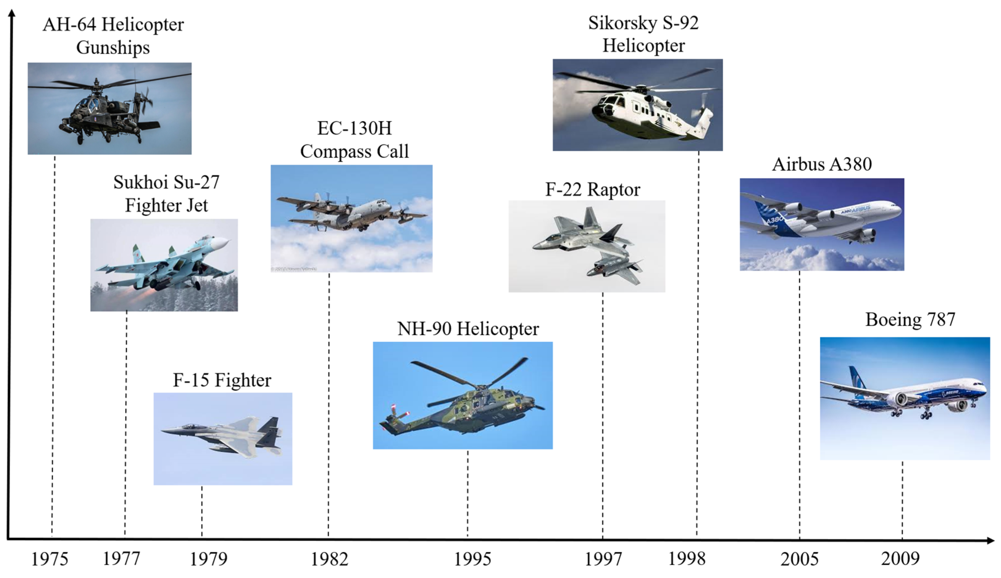
In 1948, the Boeing B877 aircraft was equipped with an evaporative cooling system, marking the first application of evaporative cooling in aircraft within the aviation field. However, limited by the technological conditions of that time, the evaporative cooling system failed to achieve sustained development in practical applications due to issues such as excessive weight, high volume occupation, and insufficient reliability. It wasn’t until the mid-1970s that the application of evaporative cooling in aircraft regained attention, as electronic devices saw an increase in power density and the technology of evaporative cooling advanced rapidly. Subsequently, leveraging its advantages in efficiency and lightweight, evaporative cooling technology quickly expanded to multiple scenarios in the aviation field, including ECSs and equipment cooling for military and civilian aircraft. The application history is illustrated in Figure 6.
In the field of aviation, the structure and performance of airborne evaporative cooling systems have become increasingly refined. Aircraft such as the Lantian electronic pod, EC-130H electronic reconnaissance aircraft, and F-22 fighter have widely adopted various forms of evaporative cooling systems, with performance continuously being upgraded. These systems are primarily developed and produced by Honeywell and Hansen. These evaporative cooling systems and their components are designed with excellence, featuring compact structures and high integration. Table 4 summarizes the parameters of some typical VCSs currently in use.
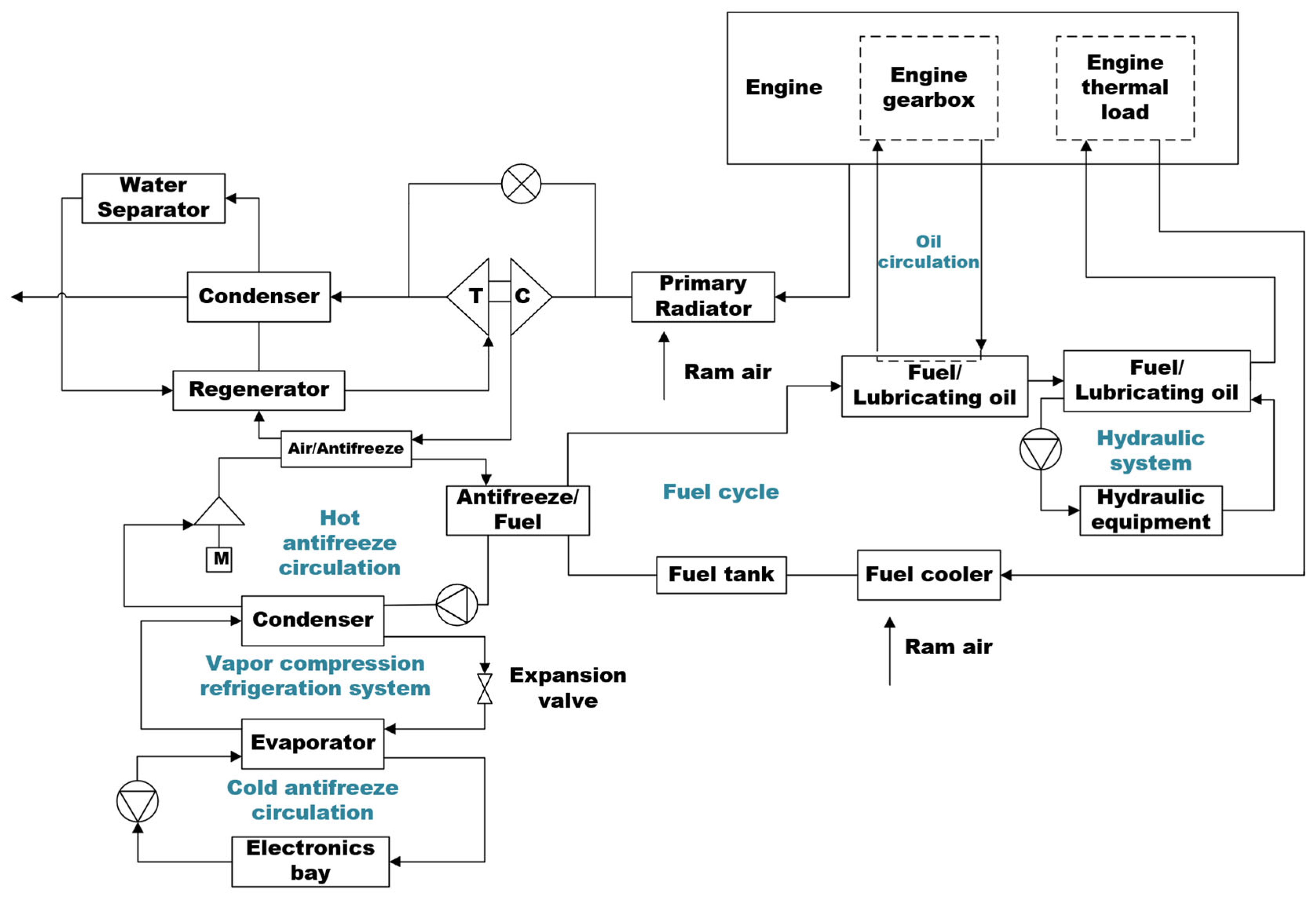
Taking the F-22 fighter as an example, its ECS/TMS is a fully integrated ECS, as illustrated in Figure 7 [34]. This system provided thermal regulation for both the pilot and avionics equipment across the entire flight envelope. Within this architecture, the cold PAO system and the hot PAO system interface with the evaporator section to form a liquid cooling loop. This integrated subsystem delivered refrigeration capacity to primary electronic equipment and supports air cycle cooling, with fuel serving as the ultimate heat sink.
The ECS of the LANTIRN pod employed an independent, high-efficiency VCS to ensure reliable operation of its onboard equipment. The pod’s ECS cools the liquid refrigerant (Coolanal 25) by evaporating Freon R114 in the evaporator, and then uses the cooled liquid refrigerant to absorb the thermal load of electronic equipment inside the pod. The condenser uses ram air as the cold source. When the ambient air temperature is low, the compressor can be controlled to shut down, and the bypass cooling loop is opened, allowing the refrigerant to directly dissipate the thermal load into the ram air through the condenser/bypass heat exchanger. Within the pod’s flight envelope and during ground operation, the pod’s thermal load is 0.2 to 3.3 kW, requiring the supply temperature of the refrigerant to the electronic equipment to be controlled within the range of 4 to 29 °C [80].
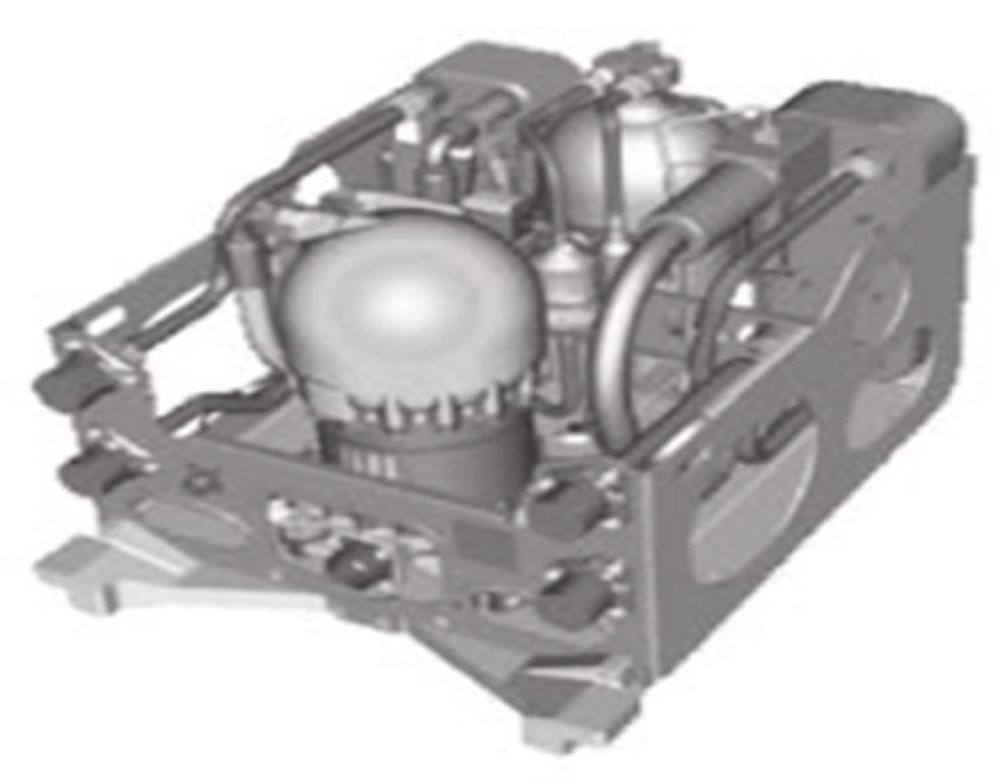
The Boeing 787 passenger aircraft utilized a VCS as an auxiliary cooling unit to provide refrigeration for aircraft galleys while delivering subcooling capacity to the cabin air conditioning system, as shown in Figure 8. This integrated vapor compression refrigeration module, installed in the rear cargo compartment bulk area, featured its condenser cooled by Power Conversion System coolant and transferred evaporator cooling output through integrated refrigerant circulation. The unit operated as a quasi-two-stage VCS weighing 76 kg with a rated cooling capacity of 35 kW.
The auxiliary cooling system of the Airbus A380 aircraft also applies an VCS, which can provide cooling for the kitchen, drinking water, and electronic equipment. The system is mainly composed of cooling and refrigeration units (CRU), air conditioning units (ACU), pump units, liquid main lines, and other components. In the CRU, the refrigerant generates cooling through a single-stage vapor compression refrigeration cycle. The generated cooling is pumped to the ACU via the liquid main line and then used to cool areas such as the kitchen. Among them, the compressor used in the CRU is a rolling rotor compressor, with a speed that can be adjusted by frequency conversion within the range of 2250 rpm~8000 rpm. The condenser and evaporator are both aluminum alloy plate-fin type, with an evaporating temperature of −9 °C, a refrigerating capacity of 15 kW, and a single CRU unit weighing 83 kg [34].

4. New Challenges Under Large-Temperature-Range Refrigeration Demand

In recent years, the contradiction between the rapidly increasing thermal load on board and the limited available heat sink has become increasingly prominent. While the speed of aircraft is increasing, flight times are extending, and high-energy weapons are continuously developing [81], the total amount of fuel available as a heat sink is limited, causing the aircraft’s fuel heat sink temperature to rise. In the latter half of the flight, it has already reached a high-temperature state, which requires a higher condensing temperature. On the other hand, new weapons require a lower temperature control compared to existing electronic equipment [82]. Based on these two points, the onboard refrigeration cycle will face a larger temperature difference for cooling. However, existing systems generally use a single-stage. In the CRU, the refrigerant generates cooling through a single-stage vapor compression refrigeration cycle, allowing a very limited range of working temperature differences (the difference between the condensing temperature and the evaporating temperature), resulting in very low efficiency or even failure to operate under large temperature differences.
Therefore, future onboard VCSs need to have a wider operating temperature span range and high efficiency under large temperature spans, which has become one of the prominent bottlenecks in the field of aircraft thermal management. Developing onboard large-temperature-range refrigeration technology is of great scientific significance for the development of aeronautical science and technology and is also an important support for the thermal management of next-generation advanced fighter jets.
Table 5 summarizes the inherent characteristics and advantages and disadvantages of various VCSs. From the perspective of adapting to new air-launched weapon cooling and high fuel heat sink temperatures during long endurance, both dual-circuit cascade vapor compression refrigeration and mixed refrigerant auto-cascade vapor compression refrigeration meet the requirements to achieve operation under a large temperature span of 80–100 °C.
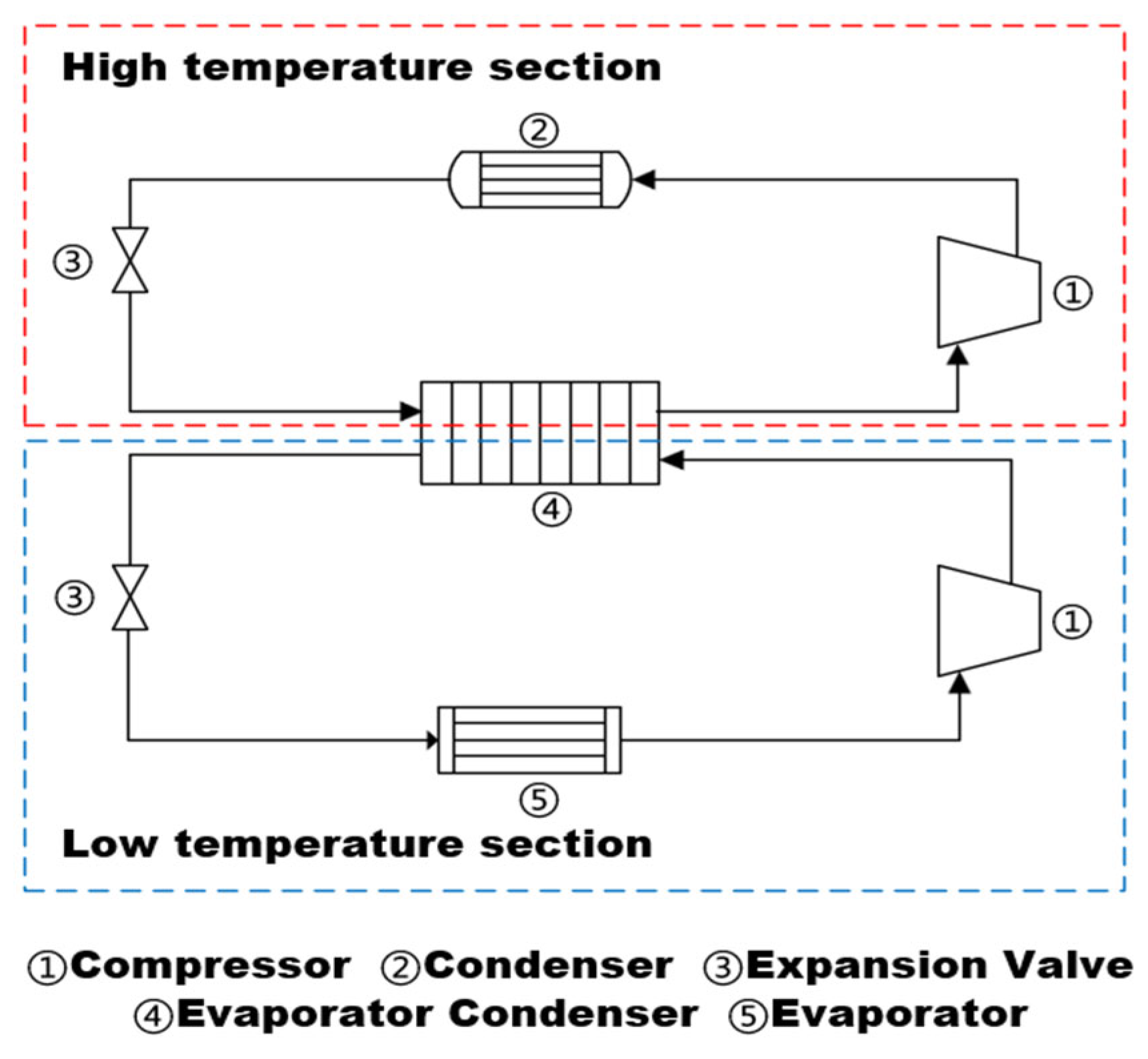
As shown in Figure 9, the dual-circuit cascade system employs two independent refrigeration circuits, each using refrigerants with different boiling points, and couples heat exchange through a condensing-evaporating heat exchanger. In the high-temperature circuit, the high-temperature refrigerant circulates under the drive of a high-temperature compressor, providing cooling to the low-temperature circuit through the condensing-evaporating heat exchanger while releasing heat to the environment in the condenser. In the low-temperature circuit, the low-temperature refrigerant, driven by a low-temperature compressor, absorbs cooling provided by the high-temperature circuit and enters the evaporator to produce low temperatures. The main advantage of the dual-circuit cascade system is that by using refrigerants with lower normal boiling points in the low-grade circuit, it can achieve lower evaporation temperatures at moderate (i.e., near atmospheric) evaporation pressures [83,84].
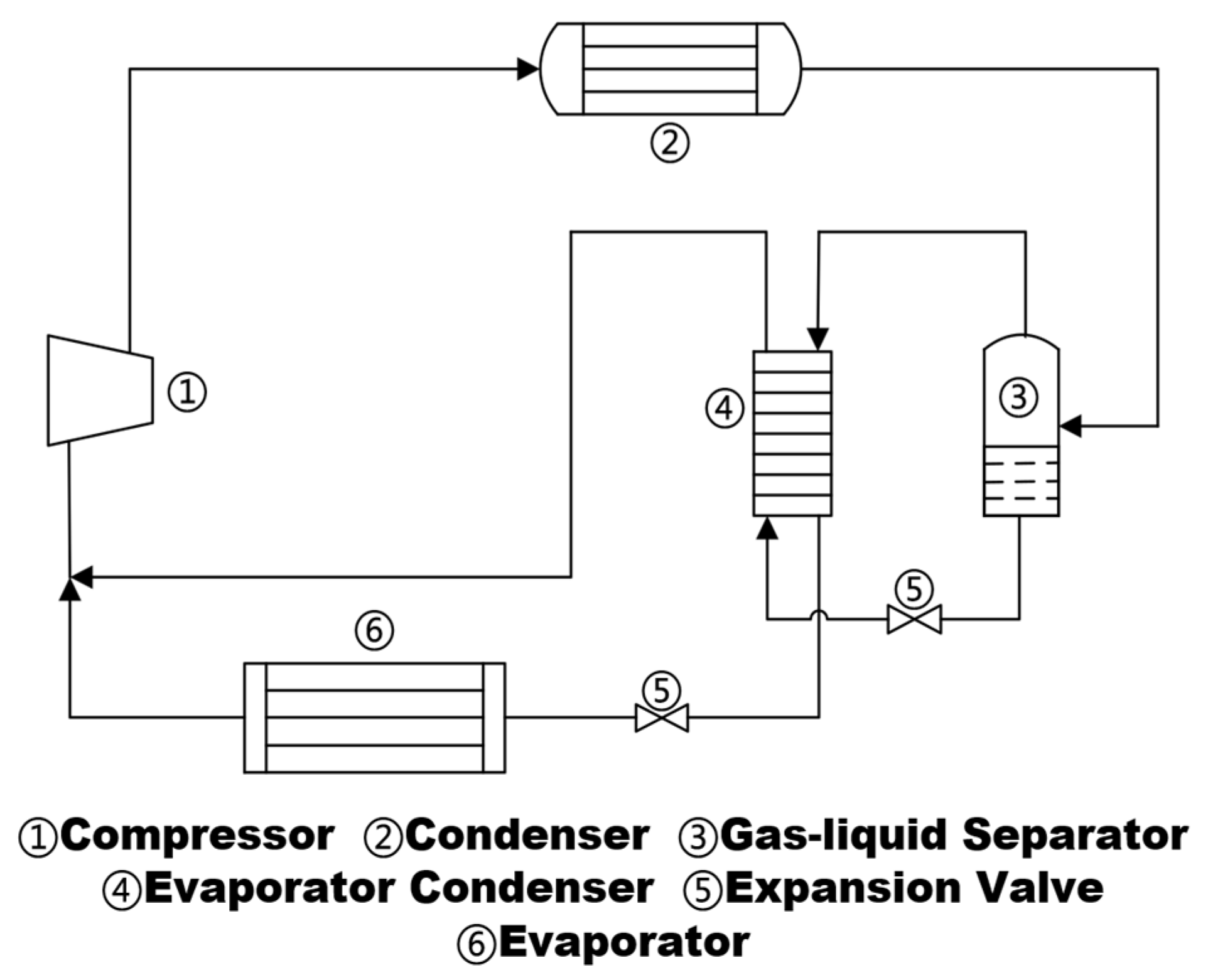
The auto-cascade refrigeration system uses a mixed refrigerant and achieves multi-stage cascade through a single compressor, greatly simplifying the refrigeration system [85,86]. As shown in Figure 10, the high-temperature, high-pressure mixed refrigerant vapor discharged from the compressor enters the condenser to release heat and condense. Due to the different boiling points of the mixed refrigerant, most of the high-boiling-point refrigerant and a small amount of low-boiling-point refrigerant condense into liquid in the condenser, while most of the low-boiling-point refrigerant remains in a gaseous state. The mixed refrigerant enters the gas-liquid separator, where it is divided into two streams: one is a liquid mixed refrigerant rich in high-boiling-point refrigerant, which is throttled by a expansion valve and enters the condensing-evaporating heat exchanger to absorb heat and evaporate; the other is a gaseous mixed refrigerant rich in low-boiling-point refrigerant, which condenses into liquid in the condensing-evaporating heat exchanger, then passes through an expansion valve into the evaporator to absorb heat from the cooled substance, achieving refrigeration. Finally, the vapor rich in low-boiling-point refrigerant is mixed with the vapor rich in high-boiling-point refrigerant and then drawn into and compressed by the compressor, thus completing the entire cycle [87,88,89,90,91].
Due to the more complex structure of the dual-circuit cascade vapor compression refrigeration system, which has two compressors, while the mixed refrigerant auto-cascade VCS only requires one compressor, the weight and retrofitting difficulty are significantly reduced. Therefore, compared to the dual-circuit cascade VCS, the mixed refrigerant auto-cascade VCS is a more preferred solution [92].
However, the application of the mixed refrigerant auto-cascade vapor compression refrigeration under airborne conditions still requires the following research:
First, compared to pure refrigerant VCSs, the performance of auto-cascaded refrigeration systems using mixed refrigerants is significantly influenced by the refrigerant composition. Pure refrigerant cycles consist of only one substance; once the refrigerant type is determined, there is no issue of composition affecting performance. However, for auto-cascaded refrigeration systems with mixed refrigerants, different refrigerant mixtures exhibit entirely distinct heat transfer and pressure characteristics, leading to variations in startup performance and energy efficiency. Understanding the concentration changes of mixed refrigerants under optimal cycle conditions is essential to grasp the system’s dynamic operating characteristics and thereby improve the thermodynamic performance of auto-cascaded systems. Nevertheless, current research on component optimization for auto-cascaded refrigeration systems within the target temperature range of this project is notably scarce. Existing studies primarily involve simulation analyses, with a near absence of experimental data for reference. Therefore, it is highly necessary to conduct combined experimental and simulation research on mixed refrigerant composition optimization for auto-cascaded systems, considering the specific environmental conditions of airborne applications.
Second, the gas-liquid separation effect in the gas-liquid separator of the mixed refrigerant auto-cascade refrigeration system significantly affects the reliable operation of the system, and ensuring good gas-liquid separation of its gas-liquid separator in the aircraft environment is highly challenging. This is because, due to different boiling points, the mixed refrigerant auto-cascade VCS causes gas and liquid phases to enrich separately in the gas-liquid separator. The evaporation heat absorption in the evaporator depends on the low-boiling-point refrigerant, so only efficient gas-liquid separation can ensure sufficient low-boiling-point refrigerant in the evaporator, i.e., effective gas-liquid separation is crucial for the refrigeration effect in the evaporator. Meanwhile, compared to the gas-liquid separation issues in ground-based single-refrigerant systems, the gas-liquid separator in this system involves a mixture of two working fluids, and the influence of overloading and tilt angles in the aircraft environment makes this separation problem more complex and challenging. Currently, research and applications of quasi-secondary systems similar to auto-cascade refrigeration, which rely on gas-liquid separation for efficient cooling, have demonstrated the feasibility of efficient gas-liquid separation in the aviation field, such as the gas-liquid separator on the B787. Additionally, worldwide simulation research on gas-liquid separators under aircraft conditions [47] has also confirmed their feasibility. However, there is still a lack of research on the gas-liquid separation characteristics of mixed refrigerants under aircraft conditions. Through technical breakthroughs in the internal flow of gas-liquid separators under varying overloading conditions and the optimization design of gas-liquid separators, it is essential to address this challenge. Therefore, studying the effects of aircraft overloading and attitude changes, as well as the non-azeotropic properties of mixed refrigerants on the two-phase flow and separation process in gas-liquid separators, and achieving efficient gas-liquid separation under these conditions are key to the application of mixed refrigerant auto-cascade refrigeration in aircraft environments.
Third, as shown in the research on control strategies by relevant scholars [52,53,73,74,75,76,77,78,79] in the previous sections, the current control methods for aircraft VCSs are still relatively traditional and limited. There is a lack of dedicated research on control methods specifically for aircraft VCSs. The existing control feedback strategies for aircraft VCSs can only meet basic control requirements, but they struggle to resolve the temperature control lag caused by thermal inertia under unpredictable disturbances. The auto-cascade VCS has two throttle valves, and during actual operation, the two throttle valves need to be coordinated to achieve optimal performance, which is more complex compared to the single-stage VCS with only one throttle valve. Rapid response and precise control under the coordination of two throttle valves involve achieving both dynamic and steady-state performance of the system, which are key technologies for ensuring energy efficiency and reliable operation. Therefore, to significantly improve the response speed, accuracy, and predictive capability of existing controls, developing control technologies based on model prediction and intelligent optimization is a core technology that needs to be broken through for aircraft VCSs in future aircraft environments.

5. Conclusions

This paper provides a review of worldwide research progress on vapor compression refrigeration technology for aircraft, elaborating on the experimental and simulation research conducted by scholars worldwide on performance optimization, dynamic characteristics, and control strategies in airborne vapor compression refrigeration cycles, and introduces the development history and typical applications of foreign airborne VCSs. The main conclusions are as follows:
Regarding the research on vapor compression refrigeration technology for aircraft, significant progress has been made in recent years. At the equipment level, performance boundaries have been pushed through lightweight and compact design, enabling micro refrigeration systems to achieve COPs of 1.04 to 5.80 approaching those of larger systems. In terms of refrigerant, the universal applicability of the optimal refrigerant charge amount has been established, providing support for efficiency optimization under dynamic operating conditions. However, there are still many shortcomings: In terms of dynamic characteristics, existing models are mostly based on laboratory environments or simplified assumptions, making it difficult to accurately predict system performance fluctuations under extreme conditions such as high-altitude cruise, rapid ascent, and emergency descent. There is a lack of in-depth exploration of the response mechanisms and modeling accuracy for unsteady conditions; In terms of control strategies, most research still relies on traditional PID control algorithms, showing insufficient adaptability to complex dynamic conditions. Although intelligent algorithms such as fuzzy control and neural networks have been introduced in recent years, practical applications still face challenges of insufficient data and real-time performance; In terms of system performance, current performance optimization research primarily focuses on improvements to individual components, lacking systematic collaborative optimization.
In recent years, the cooling requirements for new airborne weapons and long-endurance operations under high thermal loads have placed higher demands on the refrigeration efficiency of airborne VCSs across large temperature ranges. The maximum temperature difference between the condensation temperature and evaporation temperature for current single-stage VCSs for aircrafts is approximately limited to 55 °C. The issue of poor performance or even failure of existing systems under large temperature ranges urgently needs to be addressed. Among the solutions to meet this demand, auto-cascade vapor compression refrigeration has become the most preferred option due to its ability to meet large temperature range requirements, low weight, and ease of modification. For the application of auto-cascade VCSs in airborne environments, the core technologies that need to be broken through in the future include the optimization technology of mixed refrigerant composition under airborne conditions, the efficient gas-liquid separation technology of mixed refrigerant under varying overload and attitude conditions, and the high-efficiency and reliable control technology based on model prediction and intelligent optimization. In the future, auto-cascade refrigeration is expected to play a greater role in the thermal management field of aircraft.

Funding

The authors gratefully thank the financial support from Aeronautical Science Fund (No. 20240028074001).

Conflicts of Interest

The authors declare no conflict of interest.

Abbreviations

The following abbreviations are used in this manuscript:
ACAlternating current
ACS Air cycle system
ACUAir conditioning unit
BPBackpropagation
COP Coefficient of performance
CRUCooling and refrigeration unit
DCDirect current
ECSEnvironmental control system
EEV Electronic expansion valve
evaEvaporator
FMEAFailure mode and effects analysis
GA-PCAGenetic Algorithm-Principal Component Analysis
LOVCSVapor compression system and a lubrication system
LQGLinear quadratic Gaussian
MBSEModel-based system engineering
PPressure
PSO-SVMParticle swarm optimization-support vector machine
sEntropy
setSet value
SROTSecondary refrigerant outlet temperature
TMSThermal management system
TTemperature
VSC Variable speed compressor
VGTime-varying gravity
VCSVapor compression system

References

  1. Coutinho, M.; Bento, D.; Souza, A.; Cruz, R.; Afonso, F.; Lau, F.; Suleman, A.; Barbosa, F.R.; Gandolfi, R.; Affonso, W.; et al. A Review on the Recent Developments in Thermal Management Systems for Hybrid-Electric Aircraft. Appl. Therm. Eng. 2023, 227, 120427. [Google Scholar] [CrossRef]
  2. Xu, J.; Tan, H.; Wu, J.; Han, J.; Su, S.; Lyu, H. Optimization Method of Heat Transfer Architecture for Aircraft Fuel Thermal Management Systems. Chin. J. Aeronaut. 2025, 38, 103452. [Google Scholar] [CrossRef]
  3. Wang, R.; Dong, S.; Jiang, H.; Li, P.; Zhang, H. Parameter-Matching Algorithm and Optimization of Integrated Thermal Management System of Aircraft. Aerospace 2022, 9, 104. [Google Scholar] [CrossRef]
  4. Tu, M.; Yuan, G.; Xue, F.; Wang, X. Application of Integrated Thermal Management in the Development of Advanced Fighter Systems. Acta Aeronaut. Astronaut. Sin. 2020, 41, 136–146. (In Chinese) [Google Scholar]
  5. Zhu, X.; Zhu, W.; Zhu, L.; Huang, Z.; Wen, J.; He, X.; Meng, X.; Dai, N.; Xiong, G. Research the effects of high +Gz exposure on the kidney tissue and function of pilots. J. Hunan Norm. Univ. (Med. Ed.) 2021, 18, 93–95. (In Chinese) [Google Scholar]
  6. Bao, W. Research on Fighter Dynamics Modeling and Maneuver Decision Making for Aerial Threat Targets. Master’s Thesis, Huazhong University of Science and Technology, Wuhan, China, 2021. (In Chinese). [Google Scholar]
  7. Ouyang, Z.; Nikolaidis, T.; Jafari, S. Integrated Power and Thermal Management Systems for Civil Aircraft: Review, Challenges, and Future Opportunities. Appl. Sci. 2024, 14, 3689. [Google Scholar] [CrossRef]
  8. Pal, D.; Severson, M. Liquid Cooled System for Aircraft Power Electronics Cooling. In Proceedings of the 2017 16th IEEE Intersociety Conference on Thermal and Thermomechanical Phenomena in Electronic Systems (ITherm), Orlando, FL, USA, 30 May–2 June 2017; pp. 800–805. [Google Scholar] [CrossRef]
  9. Bukar, A.M.; Almerbati, A.; Shuja, S.Z.; Zubair, S.M. Enhancing Solar PV Panel Performance Through Active and Passive Cooling Techniques: A Comprehensive Review. Renew. Sustain. Energy Rev. 2025, 216, 115611. [Google Scholar] [CrossRef]
  10. Rashid, F.L.; Al-Obaidi, M.A.; Azziz, H.N.; Abdalrahem, M.K.; Ameen, A.; Eleiwi, M.A.; Homod, R.Z.; Kadhim, S.A.; Agyekum, E.B.; Bouabidi, A. Enhancing Heat Pipe Performance: The Influence of Nanofluids on Thermal Management Technologies—A Comprehensive Review. Int. J. Thermofluids 2025, 28, 101311. [Google Scholar] [CrossRef]
  11. Jain, N.; Alleyne, A.G. Thermodynamics-Based Optimization and Control of Vapor-Compression Cycle Operation: Optimization Criteria. In Proceedings of the 2011 American Control Conference, San Francisco, CA, USA, 29 June–1 July 2011; IEEE: San Francisco, CA, USA, 2011; pp. 1352–1357. [Google Scholar] [CrossRef]
  12. Mahindru, D.V.; Mahendru, P. Environmental Control System for Military and Civil Aircraft. Glob. J. Res. Eng. 2011, 11, 1–7. [Google Scholar]
  13. Pérez-Grande, I.; Leo, T.J. Optimization of a Commercial Aircraft Environmental Control System. Appl. Therm. Eng. 2002, 22, 1885–1904. [Google Scholar] [CrossRef]
  14. Chaturvedi, S.; Sharma, N.K.; Ranganayakulu, C. Exergy Analysis and Performance Evaluation of a Vapor Compression Refrigeration System Using R-134a, R-600a, and R-125. Int. J. Refrig. 2025, 175, 74–84. [Google Scholar] [CrossRef]
  15. Biru, F.; Tafesse, G.; Nigussie, S.; Zanj, A. Experimental Investigation of Phase Change Material Integrated Vapor Compression Refrigeration System. Appl. Therm. Eng. 2025, 270, 126118. [Google Scholar] [CrossRef]
  16. Jiang, J.; Yang, Q.; Yin, T.; Zheng, Z.; Zhao, Y.; Liu, G.; Li, L. Comparative Thermodynamic Study of CO2 Transcritical Supermarket Booster Refrigeration System Combined with Vapor Injection and Parallel Compression. Int. J. Refrig. 2025, 170, 70–84. [Google Scholar] [CrossRef]
  17. Salim, M.S.; Kim, M.-H. Multi-Objective Thermo-Economic Optimization of a Combined Organic Rankine Cycle and Vapour Compression Refrigeration Cycle. Energy Convers. Manag. 2019, 199, 112054. [Google Scholar] [CrossRef]
  18. Sheng, J.; Zhang, H.; Wu, Z.; Lei, J. Current Status of Refrigeration and Air Conditioning Technology in Aircraft Environmental Control Systems. J. Refrig. 2020, 41, 22–23. (In Chinese) [Google Scholar]
  19. Affonso, W.; Gandolfi, R.; Dos Reis, R.J.N.; Da Silva, C.R.I.; Rodio, N.; Kipouros, T.; Laskaridis, P.; Chekin, A.; Ravikovich, Y.; Ivanov, N.; et al. Thermal Management Challenges for HEA—FUTPRINT 50. IOP Conf. Ser. Mater. Sci. Eng. 2021, 1024, 012075. [Google Scholar] [CrossRef]
  20. Affonso, W.; Tavares, R.; Barbosa, F.R.; Gandolfi, R.; Dos Reis, R.J.N.; Da Silva, C.R.I.; Kipouros, T.; Laskaridis, P.; Enalou, H.B.; Chekin, A.; et al. System Architectures for Thermal Management of Hybrid-Electric Aircraft—FutPrInt50. IOP Conf. Ser. Mater. Sci. Eng. 2022, 1226, 012062. [Google Scholar] [CrossRef]
  21. Van Heerden, A.S.J.; Judt, D.M.; Jafari, S.; Lawson, C.P.; Nikolaidis, T.; Bosak, D. Aircraft Thermal Management: Practices, Technology, System Architectures, Future Challenges, and Opportunities. Prog. Aerosp. Sci. 2022, 128, 100767. [Google Scholar] [CrossRef]
  22. Merzvinskas, M.; Bringhenti, C.; Tomita, J.T.; De Andrade, C.R. Air Conditioning Systems for Aeronautical Applications: A Review. Aeronaut. J. 2020, 124, 499–532. [Google Scholar] [CrossRef]
  23. Silva-Romero, J.C.; Belman-Flores, J.M.; Aceves, S.M. A Review of Small-Scale Vapor Compression Refrigeration Technologies. Appl. Sci. 2024, 14, 3069. [Google Scholar] [CrossRef]
  24. Alsouda, F.; Bennett, N.S.; Saha, S.C.; Salehi, F.; Islam, M.S. Vapor Compression Cycle: A State-of-the-Art Review on Cycle Improvements, Water and Other Natural Refrigerants. Clean Technol. 2023, 5, 584–608. [Google Scholar] [CrossRef]
  25. Asli, M.; König, P.; Sharma, D.; Pontika, E.; Huete, J.; Konda, K.R.; Mathiazhagan, A.; Xie, T.; Höschler, K.; Laskaridis, P. Thermal Management Challenges in Hybrid-Electric Propulsion Aircraft. Prog. Aerosp. Sci. 2024, 144, 100967. [Google Scholar] [CrossRef]
  26. Frey, A.C.; Bosak, D.; Madrid, E.; Stonham, J.; Sangan, C.M.; Pountney, O.J. Thermal Management in High Temperature Proton Exchange Membrane Fuel Cells for Aircraft Propulsion Systems. Prog. Aerosp. Sci. 2025, 153, 101052. [Google Scholar] [CrossRef]
  27. Homitz, J.; Scaringe, R.; Cole, G. Evaluation of a Vapor-Compression Thermal Management System for Reliability While Operating Under Thermal Transients; SAE Technical Paper 2010-01-1733; SAE: Warrendale, PA, USA, 2010. [Google Scholar] [CrossRef]
  28. Newman, R.W.; Dooley, M.; Lui, C. Efficient Propulsion, Power, and Thermal Management Integration. In Proceedings of the 49th AIAA/ASME/SAE/ASEE Joint Propulsion Conference, San Jose, CA, USA, 14–17 July 2013. [Google Scholar] [CrossRef]
  29. Lui, C.; Dooley, M. Electric Thermal Management Architectures. In Proceedings of the SAE 2013 AeroTech Congress & Exhibition, Montréal, QC, Canada, 24–26 September 2013; SAE International: Warrendale, PA, USA, 2013. [Google Scholar] [CrossRef]
  30. Qi, S.; Xu, Z.; Wang, J.; Xu, Y. Dynamic Characteristics of a Two-Phase Mechanically Pumped Cooling Loop for Avionics. Case Stud. Therm. Eng. 2025, 67, 105830. [Google Scholar] [CrossRef]
  31. Mancin, S.; Zilio, C.; Righetti, G.; Rossetto, L. Mini Vapor Cycle System for High Density Electronic Cooling Applications. Int. J. Refrig. 2013, 36, 1191–1202. [Google Scholar] [CrossRef]
  32. Erkinaci, T.; Coskun, F.; Cotur, A.; Onler, R.; Serincan, M.F. Experimental and Numerical Investigation of a Compact Vapor Compression Refrigeration System for Cooling of Avionics in Harsh Environments. Appl. Therm. Eng. 2024, 236, 121663. [Google Scholar] [CrossRef]
  33. Zhi, R.; Ma, R.; Zhang, D.; Wu, Y. Experimental Research on a Lightweight Miniature Wankel Compressor for a Vapor Compression Refrigeration System in Aerospace. Sustainability 2023, 15, 8826. [Google Scholar] [CrossRef]
  34. Gao, F. Experimental and Refrigerant Charge Research on Aircraft Evaporative Cycle Refrigeration System. Master’s Thesis, Nanjing University of Aeronautics and Astronautics, Nanjing, China, 2019. (In Chinese). [Google Scholar]
  35. Puntel, A.; Emo, S.; Michalak, T.E.; Ervin, J.; Byrd, L.; Tsao, V.; Reitz, T. Refrigerant Charge Management and Control for Next-Generation Aircraft Vapor Compression Systems; SAE International: Warrendale, PA, USA, 2013; SAE Technical Paper 2013-01-2241. [Google Scholar] [CrossRef]
  36. Byrd, L.; Cole, A.; Emo, S.; Ervin, J.; Michalak, T.E.; Tsao, V. In-Situ Charge Determination for Vapor Cycle Systems in Aircraft; SAE International: Warrendale, PA, USA, 2012; SAE Technical Paper 2012-01-2187. [Google Scholar] [CrossRef]
  37. Kang, H.; Heo, J.; Kim, Y. Performance Characteristics of a Vapor Compression Cooling Cycle Adopting a Closed-Loop Air-Circulation System for Avionic Reconnaissance Equipment. Int. J. Refrig. 2012, 35, 785–794. [Google Scholar] [CrossRef]
  38. Wang, R.; Gao, Z.; Yang, H.; Hu, W.; Zhan, H. The Impact of Aircraft Refrigeration Source Parameters on the Performance of Evaporative Cycle Systems. J. Chem. Ind. Eng. 2020, 71 (Suppl. S1), 212–219. (In Chinese) [Google Scholar]
  39. Fan, J.; Pang, L.; Liu, D.; Zhang, H.; Zhao, M. Test Performance of Key Components in Helicopter Liquid Cooling/Evaporative Refrigeration Combined System. J. Chem. Ind. Eng. 2020, 71 (Suppl. S2), 80–84. (In Chinese) [Google Scholar]
  40. Sung, T.; Lee, D.; Kim, H.S.; Kim, J. Development of a Novel Meso-Scale Vapor Compression Refrigeration System (mVCRS). Appl. Therm. Eng. 2014, 66, 453–463. [Google Scholar] [CrossRef]
  41. Sung, T.; Kim, Y.J.; Kim, H.S.; Kim, J. Empirical Modeling and Robust Control of a Novel Meso-Scale Vapor Compression Refrigeration System (mVCRS). Int. J. Refrig. 2017, 77, 99–115. [Google Scholar] [CrossRef]
  42. Xu, Y.; Yan, Z.; Xia, W. A Novel System for Aircraft Cabin Heating Based on a Vapor Compression System and Heat Recovery from Engine Lubricating Oil. Appl. Therm. Eng. 2022, 212, 118544. [Google Scholar] [CrossRef]
  43. Zilio, C.; Righetti, G.; Mancin, S.; Hodot, R.; Sarno, C.; Pomme, V.; Truffart, B. Active and Passive Cooling Technologies for Thermal Management of Avionics in Helicopters: Loop Heat Pipes and Mini-Vapor Cycle System. Therm. Sci. Eng. Prog. 2018, 5, 107–116. [Google Scholar] [CrossRef]
  44. Price, D.C. Thermal Management of Military Fighter Aircraft Electro-Optics Pod: An Invited Paper. In Ninteenth Annual IEEE Semiconductor Thermal Measurement and Management Symposium; IEEE: Piscataway, NJ, USA, 2003; pp. 341–350. [Google Scholar] [CrossRef]
  45. Yang, G.; Xia, W.; Zhang, X. Aircraft Quasi-Two-Stage Compression Evaporative Cycle Refrigeration Technology. J. Nanjing Univ. Aeronaut. Astronaut. 2017, 49 (Suppl. S1), 35–39. (In Chinese) [Google Scholar]
  46. Yang, B.; Zhang, X. Optimal Design of Condenser for Aircraft Evaporative Cycle System. Henan Sci. Technol. 2021, 40, 21–23. (In Chinese) [Google Scholar]
  47. Wen, T.; Zhan, H.; Zhang, D.; Lu, L. Development of Evaporation Pressure-Capacity Control Strategy for Aircraft Vapor Cycle System. Int. J. Refrig. 2017, 83, 14–22. [Google Scholar] [CrossRef]
  48. Michalak, T.; Emo, S.; Ervin, J. Control Strategy for Aircraft Vapor Compression System Operation. Int. J. Refrig. 2014, 48, 10–18. [Google Scholar] [CrossRef]
  49. Byrd, L.; Cole, A.; Cranston, B.; Emo, S.; Ervin, J.; Michalak, T.E. Two Phase Thermal Energy Management System; SAE: Warrendale, PA, USA, 2011; SAE Technical Paper 2011-01-2584. [Google Scholar] [CrossRef]
  50. Sun, C.; Wang, H.; Jiang, Y.; Gao, Z.; Wang, J. A Hybrid Piecewise FDD Strategy for Refrigeration Charge Fault of Airborne Vapor-Compression Cycle System. Int. J. Refrig. 2022, 135, 164–173. [Google Scholar] [CrossRef]
  51. Sun, C. Research on Physical Integration and Health Management Technology of Aircraft Evaporative Cycle Refrigeration System. Ph.D. Thesis, Nanjing University of Aeronautics and Astronautics, Nanjing, China, 2022. (In Chinese). [Google Scholar]
  52. Liu, X.; Sun, C.; Jiang, Y.; Zheng, W.; Gao, Z. Research on Fault Diagnosis and Visualization Software of Aircraft Refrigeration System. Refrig. Air Cond. 2019, 33, 457–461. (In Chinese) [Google Scholar]
  53. Yang, B.; Zhang, X. Optimal Design of Aircraft Evaporative Cycle System Based on MBSE. China Sci. Technol. Inf. 2022, 29–30. (In Chinese) [Google Scholar] [CrossRef]
  54. Cao, H.; Zhao, J. Steady-State Simulation of Aircraft Evaporative Refrigeration Cycle. Comput. Simul. 2007, 40–42. (In Chinese) [Google Scholar] [CrossRef]
  55. Li, Y.; Liu, Z.; Shi, G.; Shi, H.; Cheng, D. Simulation Study on Aircraft Evaporative Cycle Refrigeration System. World Sci. Technol. Res. Dev. 2012, 34, 398–402. (In Chinese) [Google Scholar]
  56. Kim, J.; Kwon, K.; Roy, S.; Garcia, E.; Mavris, D.N. Megawatt-Class Turboelectric Distributed Propulsion, Power, and Thermal Systems for Aircraft. In Proceedings of the 2018 AIAA Aerospace Sciences Meeting, Kissimmee, FL, USA, 8–12 January 2018; American Institute of Aeronautics and Astronautics: Kissimmee, FL, USA, 2018. [Google Scholar] [CrossRef]
  57. Shetty, J.; Lawson, C.P.; Shahneh, A.Z. Simulation for Temperature Control of a Military Aircraft Cockpit to Avoid Pilot’s Thermal Stress. CEAS Aeronaut. J. 2015, 6, 319–333. [Google Scholar] [CrossRef]
  58. Wang, J.; Gao, Z.; Li, S.; Wang, Q. Research on Aircraft Evaporative Cycle Refrigeration System with Economizer. Aeronaut. Sci. Technol. 2016, 27, 60–67. (In Chinese) [Google Scholar]
  59. Peng, X.; Feng, S.; Li, C.; Wang, C.; Liu, W. Impact of Refrigerant Type on the Performance of Aircraft Evaporative Cycle System. J. Nanjing Univ. Aeronaut. Astronaut. 2020, 52, 478–484. (In Chinese) [Google Scholar]
  60. Gupta, P.; Khapli, R.P.; Huliraj, R.V. Designing of Vapour Cycle Cooling System of Twin Seater Basic Trainer Aircraft. In Proceedings of the 2019 International Conference on Cutting-Edge Technologies in Engineering (ICon-CuTE), Uttar Pradesh, India, 14–16 November 2019; pp. 16–21. [Google Scholar] [CrossRef]
  61. Hu, H.; Sun, H.; Wu, C.; Wang, X.; Lv, Z. A Steady-State Simulation Model of Supplemental Cooling System Integrated with Vapor Compression Refrigeration Cycles for Commercial Airplane. Appl. Therm. Eng. 2020, 166, 114692. [Google Scholar] [CrossRef]
  62. Ablanque, N.; Torras, S.; Rigola, J.; Oliet, C. Dynamic Model of Vapor Compression Systems for Aircraft Environmental Control Systems. J. Aircr. 2024, 61, 1387–1396. [Google Scholar] [CrossRef]
  63. Sielemann, M.; Giese, T.; Oehler, B.; Gräber, M. Optimization of an Unconventional Environmental Control System Architecture. SAE Int. J. Aerosp. 2011, 4, 1263–1275. [Google Scholar] [CrossRef]
  64. Peng, X.; Jiang, H.; Li, C.; Feng, S.; Liu, W. Dynamic Simulation of Helicopter Aircraft Evaporative Cycle System Based on AMESim. J. Nav. Aeronaut. Astronaut. Univ. 2018, 33, 452–458. (In Chinese) [Google Scholar]
  65. Long, H.; Zhu, C. Dynamic Simulation of Aircraft Evaporative Cycle System. Aircr. Des. 2012, 32, 53–57. (In Chinese) [Google Scholar]
  66. Zhu, Z.; Xu, Y.; Zheng, W.; Meng, F.; Xia, W. Dynamic Characteristics of Aircraft Evaporative Cycle System in High Temperature and Humidity Environment. J. Nav. Aeronaut. Astronaut. Univ. 2020, 35, 277–284. (In Chinese) [Google Scholar]
  67. Wang, L.; Jiang, Y.; Sun, C. Dynamic Simulation of Aircraft Quasi-Two-Stage Compression Evaporative Refrigeration System. Refrig. Air Cond. 2018, 32, 235–241. (In Chinese) [Google Scholar]
  68. Li, Y.; Pan, Q.; Liu, Z.; Liu, J. Dynamic Simulation of Aircraft Evaporative Cycle Refrigeration System. J. Nanjing Univ. Sci. Technol. 2013, 37, 127–132. (In Chinese) [Google Scholar]
  69. Ablanque, N.; Torras, S.; Oliet, C.; Rovira, J.; Pérez-Segarra, C.D. Vapor Compression System Modelica Library for Aircraft ECS. In Proceedings of the 2018 Purdue Conferences. 17th International Refrigeration and Air-Conditioning Conference at Purdue, West Lafayette, IN, USA, 9–12 July 2018. [Google Scholar]
  70. Liu, H.; Jiang, H.; Dong, S.; Xue, L.; Liu, Y.; Wu, J. Simulation of an Aircraft Thermal Management System Based on Vapor Cycle Response Surface Model. Chin. J. Aeronaut. 2024, 37, 64–77. [Google Scholar] [CrossRef]
  71. Dexter, P.F.; Martinez, M.I.; Maxwell, G.C.; Watts, R.J. Centrifuge Test of an Aircraft Vapor Cycle Environmental Control System; SAE Technical Paper 922051; SAE: Warrendale, PA, USA, 1992. [Google Scholar]
  72. Watts, R.J.; Martinez, M.; Gruesbeck, W.; Skowronski, V. Test Evaluation of an Affordable Fighter Aircraft Vapor Cycle System. In Aerospace Atlantic Conference & Exposition; SAE: Warrendale, PA, USA, 1994. [Google Scholar]
  73. Zhou, H. Research on Intelligent Control Methods of Aircraft Evaporative Cycle Refrigeration System. Master’s Thesis, Nanjing University of Aeronautics and Astronautics, Nanjing, China, 2020. (In Chinese). [Google Scholar]
  74. Li, Y.; Hu, H.; Lei, R. Dynamic Modelling of Supplemental Cooling Systems with Vapor Compression Refrigeration Units in Civil Aircrafts. Appl. Therm. Eng. 2024, 248, 123285. [Google Scholar] [CrossRef]
  75. Drego, A.D.; Andersson, D.; Staack, I. Parameter Tuning of a Vapor Cycle System for a Surveillance Aircraft. Aerospace 2024, 11, 66. [Google Scholar] [CrossRef]
  76. Pollock, D.T.; Williams, M.A.; Hencey, B.M. Model Predictive Control of Temperature-Sensitive and Transient Loads in Aircraft Vapor Compression Systems. In 2016 American Control Conference (ACC); IEEE: Boston, MA, USA, 2016; pp. 575–580. [Google Scholar] [CrossRef]
  77. Zhao, M.; Liping, P. Dynamic Numerical Investigation of Airborne Vapor Cycle Cooling System. In Proceedings of the CSAA/IET International Conference on Aircraft Utility Systems (AUS 2018), Guiyang, China, 19–22 June 2018. [Google Scholar]
  78. Zhao, M.; Pang, L.; Liu, M.; Yu, S.; Mao, X. Control Strategy for Helicopter Thermal Management System Based on Liquid Cooling and Vapor Compression Refrigeration. Energies 2020, 13, 2177. [Google Scholar] [CrossRef]
  79. Jackson, S.D.; Palazotto, A.N.; Pachter, M.; Niedbalski, N. Control of Vapor Compression Cycles under Transient Thermal Loads. In AIAA Scitech 2019 Forum; American Institute of Aeronautics and Astronautics: San Diego, CA, USA, 2019. [Google Scholar] [CrossRef]
  80. Godecker, W.J.; Lentz, J.C.; Parme, C.B.; Wigmore, D.B.; Winans, K.B. Vapor Cycle System for a Fighter Aircraft—The Lantirn ECU Lessons Learned. SAE Trans. 1992, 101, 609–617. [Google Scholar]
  81. Wu, B.; Zhang, F.; Yang, M.; Ren, Z. Progress in the Application of Phase Change Thermal Energy Storage Technology in Thermal Management of High-Energy Aircraft Weapons. Mech. Res. Appl. 2020, 33, 197–199. (In Chinese) [Google Scholar]
  82. Sun, Z.; Liu, M.; Qiao, S.; Gao, Z.; Meng, F. Performance Simulation Study on Hundred Kilowatt-Level Phase Change Thermal Energy Storage Heat Exchanger for Aircraft. Aircr. Des. 2024, 44, 53–58. (In Chinese) [Google Scholar]
  83. Barbosa, J.R. Recent Developments in Vapor Compression Technologies for Small Scale Refrigeration Applications. In Proceedings of the ASME 2011 9th International Conference on Nanochannels, Microchannels, and Minichannels, Edmonton, AB, Canada, 19–22 June 2011; ASMEDC: Edmonton, AB, Canada, 2011; Volume 2, pp. 459–471. [Google Scholar] [CrossRef]
  84. Ji, S.; Liu, Z. Thermodynamic and Economic Performance Comparison Between Reverse Brayton Cycles and Cascade Refrigeration Cycles with Eco-Friendly Refrigerants. Appl. Therm. Eng. 2025, 261, 125163. [Google Scholar] [CrossRef]
  85. Shi, R.; Bai, T.; Wan, J. Performance Analysis of a Dual-Ejector Enhanced Two-Stage Auto-Cascade Refrigeration Cycle for Ultra-Low Temperature Refrigeration. Appl. Therm. Eng. 2024, 240, 122152. [Google Scholar] [CrossRef]
  86. Ye, W.; Liu, Y.; Zhou, Z.; Hu, L.; Liu, Y. Performance Prediction of an Auto-Cascade Refrigeration System Using Multiple-Algorithmic Approaches. Energy 2025, 314, 134197. [Google Scholar] [CrossRef]
  87. Rodríguez-Jara, E.Á.; Sánchez-de-la-Flor, F.J.; Expósito-Carrillo, J.A.; Salmerón-Lissén, J.M. Thermodynamic Analysis of Auto-Cascade Refrigeration Cycles, with and without Ejector, for Ultra Low Temperature Freezing Using a Mixture of Refrigerants R600a and R1150. Appl. Therm. Eng. 2022, 200, 117598. [Google Scholar] [CrossRef]
  88. Karacayli, I.; Altay, L.; Hepbasli, A. Auto-Cascade Refrigeration Systems: A Key Review with Energetic and Exergetic Perspectives. Appl. Therm. Eng. 2025, 258, 124568. [Google Scholar] [CrossRef]
  89. Li, Y.; Jing, D.; Liu, G.; Yan, G. Study of the Migration Behavior of Mixed Refrigerants and Energy Efficiency During Actuators Action Process in Auto-Cascade Refrigeration Systems. Appl. Therm. Eng. 2025, 274, 126548. [Google Scholar] [CrossRef]
  90. Liu, J.; Liu, Y.; Yan, G.; Yu, J. Thermodynamic Analysis on a Modified Auto-Cascade Refrigeration Cycle with a Self-Recuperator. Int. J. Refrig. 2022, 137, 117–128. [Google Scholar] [CrossRef]
  91. Karacayli, I.; Altay, L.; Hepbasli, A. Comparative Analysis of a Modified Cascade Refrigeration Cycle Including an Auto-Cascade Refrigeration Cycle Using Different Zeotropic Refrigerant Mixtures for Reducing the Environmental Impact. Process Saf. Environ. Prot. 2025, 193, 976–989. [Google Scholar] [CrossRef]
  92. Li, Y.; Liu, G.; Chen, Q.; Yan, G. Progress of Auto-Cascade Refrigeration Systems Performance Improvement: Composition Separation, Shift and Regulation. Renew. Sustain. Energy Rev. 2023, 187, 113664. [Google Scholar] [CrossRef]
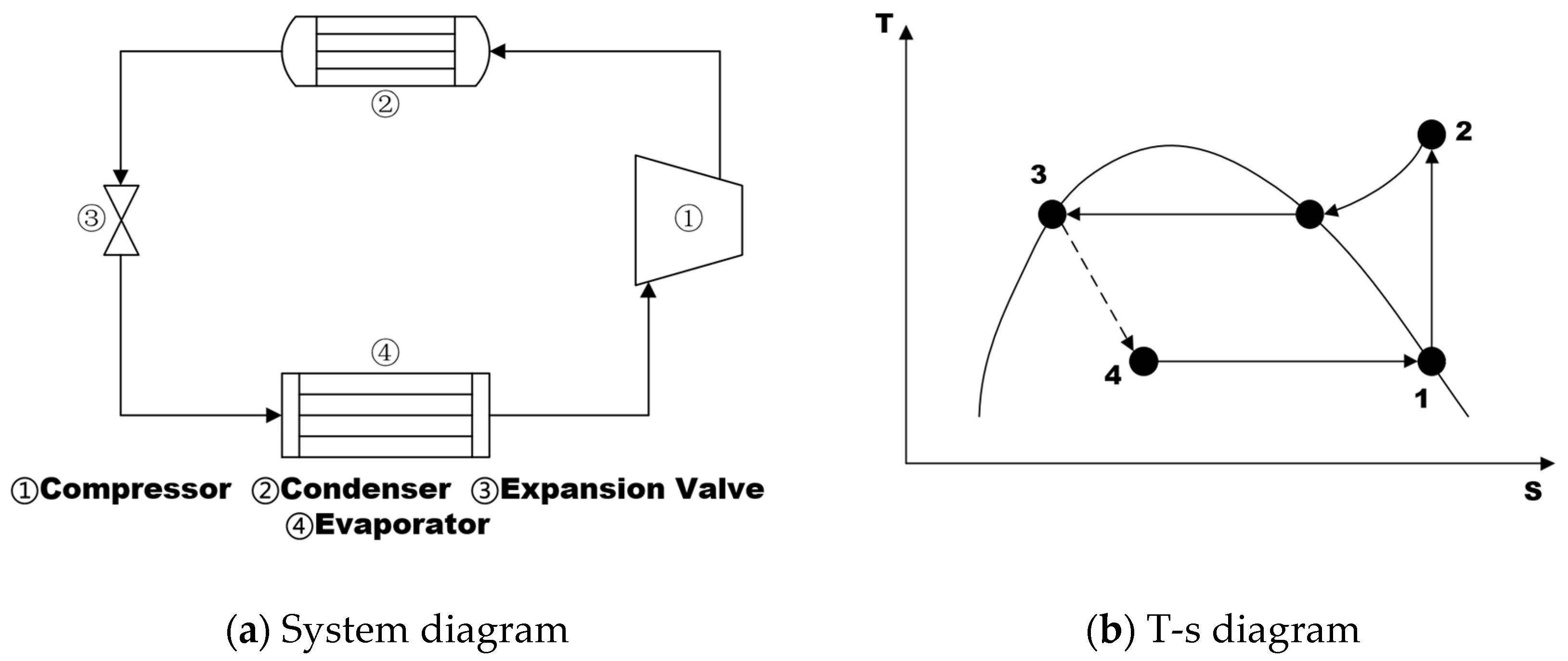
Figure 1. Schematic diagram of a single-stage VCS.
Aerospace 12 00681 g001
Figure 2. The mini-VCS designed by Mancin et al. [31].
Aerospace 12 00681 g002
Figure 3. LOVCS proposed by Xu et al. [42]. (a) For non-pressurized cabin; (b) For pressurized cabin.
Aerospace 12 00681 g003
Figure 4. An improved control strategy proposed by Wen et al. [47].
Aerospace 12 00681 g004
Figure 5. Schematic diagram of BP neural network decoupling control proposed by Zhou et al. [73].
Aerospace 12 00681 g005
Figure 6. History of Airborne VCS Application.
Aerospace 12 00681 g006
Figure 7. F-22 ECS/TMS Schematic [34].
Aerospace 12 00681 g007
Figure 8. B-787 evaporative cycle auxiliary refrigeration unit [51].
Aerospace 12 00681 g008
Figure 9. Dual- circuit cascade refrigeration cycle diagram.
Aerospace 12 00681 g009
Figure 10. Schematic diagram of auto-cascade refrigeration system.
Aerospace 12 00681 g010
Table 1. Relevant reviews on the research of VCSs compared with our review.
ReferenceResearch
Progress
of VCS
Research
Progress on
VCS for Aircraft
Application of VCS for AircraftDevelopment Trends of VCS for Aircraft Under Large-Temperature-Range Challenges
Coutinho
et al. [1]
Aerospace 12 00681 i001Aerospace 12 00681 i001Aerospace 12 00681 i002Aerospace 12 00681 i003
Affonso
et al. [19]
Aerospace 12 00681 i001Aerospace 12 00681 i001Aerospace 12 00681 i002Aerospace 12 00681 i003
Van Heerden
et al. [21]
Aerospace 12 00681 i001Aerospace 12 00681 i002Aerospace 12 00681 i002Aerospace 12 00681 i003
Merzvinskas
et al. [22]
Aerospace 12 00681 i002Aerospace 12 00681 i002Aerospace 12 00681 i002Aerospace 12 00681 i001
Silva-Romero
et al. [23]
Aerospace 12 00681 i002Aerospace 12 00681 i001Aerospace 12 00681 i001Aerospace 12 00681 i003
Alsouda
et al. [24]
Aerospace 12 00681 i002Aerospace 12 00681 i003Aerospace 12 00681 i001Aerospace 12 00681 i003
Asli
et al. [25]
Aerospace 12 00681 i001Aerospace 12 00681 i001Aerospace 12 00681 i001Aerospace 12 00681 i003
Frey
et al. [26]
Aerospace 12 00681 i002Aerospace 12 00681 i001Aerospace 12 00681 i003Aerospace 12 00681 i001
Current
review
Aerospace 12 00681 i002Aerospace 12 00681 i002Aerospace 12 00681 i002Aerospace 12 00681 i002
Aerospace 12 00681 i002—The topic was addressed in detail, Aerospace 12 00681 i001—The topic was mentioned, but further research is needed, Aerospace 12 00681 i003—The topic has not been addressed.
Table 2. Summary of Experimental Research Progress on Vapor Compression Refrigeration Technology for Aircraft.
Research
Perspective
AuthorResearch
Content
Main Results/Conclusions
Equipment Level
Vapor
Compression
Refrigeration
Qi
et al. [30]
Experimental study on VCS for aviation electronic equipmentAnalyzed changes in heated wall temperature and pressure drop under variable cold source temperature conditions for both fixed and variable pump modes; Identified impacts of low-temperature startup and heat load jumps
Mancin
et al. [31]
Experimental study on
micro VCS for airborne electronic equipment
Obtained a system with cooling capacity of 37~374 W and COP of 1.04~5.80. System design shown in Figure 2
Erkinaci
et al. [32]
Experimental study on equipment-level compact VCSAchieved 623 W cooling capacity, COP of 2.7, maintaining component temperature below ambient temperature; Suitable for harsh thermal environments
Zhi
et al. [33]
Development of lightweight miniature Wankel compressorDetermined optimal charge amount as 220 g, COP reached 2.8, verified 600-h operational reliability
Refrigerant Charge AmountGao
et al. [34]
Impact of refrigerant charge amount on system performanceDetermined the optimal refrigerant charge amount based on changes in COP, and verified its universality
Puntel
et al. [35]
Control and management issues of refrigerant charge amountDeveloped real-time refrigerant charge measurement technology and proposed a dynamic operating point optimization strategy
Byrd
et al. [36]
Method for determining appropriate refrigerant charge amountCharge amount significantly affects system performance; Analyzed system performance under static and dynamic conditions as a function of refrigerant charge
Operating Characteristics and
System
Form
Innovation
Kang
et al. [37]
Testing experiment on ACS and VCSMeasured system operating characteristics under different compressor speeds, evaporator air-side flow rates, condenser air-side flow rates, and temperatures; Optimized system performance via parameter adjustment
Wang
et al. [38]
Characteristic test of airborne VCS based on liquid-cooled evaporatorCold source inlet temperature significantly affects compressor superheat and heat source outlet temperature, but cold source flow rate impact is not significant
Fan
et al. [39]
Helicopter ECS and key component heat transfer performance testCompleted heat exchanger performance tests for evaporator and condenser, validated simulation model effectiveness, and performed parameter correction
Xu
et al. [42]
Ground experiment on vapor compression refrigeration and lubrication coupled systemAchieved heat recovery from lubricating oil and utilized it for cabin heating
Zilio
et al. [43]
Development and experiment of a novel electronic cooling systemThis system couples a loop heat pipe with a micro VCS; Experiments verified its application potential in airborne scenarios
Yang
et al. [45]
Performance test of quasi-two-stage compression VCSQuasi-two-stage system can reduce compressor speed and discharge temperature, extending lifespan and improving COP; Reduces power consumption and fuel consumption under the same power output
Control
Methods
Yang
et al. [46]
Experimental optimization Experimental study on condenser two-stage parallel flow core optimization technologySignificantly reduced condenser mass and volume by adopting an optimized series structure design; Met heat exchange requirements and passed flight test assessment
Wen
et al. [47]
Comparison and improvement of evaporation pressure control strategiesProposed an improved control strategy that can stably control evaporation pressure (420 ± 16 kPa) and temperature (20 ± 2 °C) under severe environmental conditions
Michalak
et al. [48]
Experimental study on compressor control strategy based on alternating cyclesEnhanced control characteristics and COP by modulating compressor and expansion valve
Byrd
et al. [49]
Dynamic control of multi-evaporator VCSDeveloped an optimized control strategy; System COP reached 2.39, with fast dynamic response (time constant 13 s); Supports fault detection and thermal model validation
Fault
Detection
Sun
et al. [51]
Fault mode analysis and diagnostic model (GA-PCA-BP) development for airborne VCSIdentified main fault modes based on FMEA; Experimentally simulated 9 types of gradual faults and developed corresponding diagnostic models
Liu
et al. [52]
Construction of PSO-SVM fault diagnosis model and MATLAB visualization interface designDeveloped the PSO-SVM model and GUI software; Verified its accuracy and reliability using multiple datasets
Yang
et al. [53]
Compressor startup fault analysis and communication optimization based on MBSEProposed a single-wire communication improvement scheme; Validated effectiveness through bench tests and flight tests; Has guiding significance for helicopter system design
Table 3. Summary of Simulation Research Progress on Vapor Compression Refrigeration Technology for Aircraft.
Research
Perspective
AuthorResearch ContentMain Results/Conclusions
Performance
under
Specific
Flight
Missions/
Onboard
Environments
Cao
et al. [54]
Dynamic characteristics of onboard VCS with bilateral liquid heat exchangeRefrigerant flow rate changes affect COP and superheat degree; Model effectively supports dynamic characteristic analysis
Li
et al. [55]
Optimization of VCS with bilateral liquid heat exchangeEvaporation pressure, condensation pressure, and compressor speed are key factors affecting system cooling capacity and COP
Kim
et al. [56]
Analysis of megawatt-level aircraft thermal management architectureHybrid architecture has optimal weight but high power demand; Requires increased compressor power density (P/W) and optimized refrigerant circulation for feasible design
Shetty
et al. [57]
Development of simulation model for military aircraft ECSQuantified impact of flight parameters on cockpit thermal balance; Determined required bleed air flow rate and temperature control valve modulation strategy to maintain thermal comfort index
Wang
et al. [58]
Steady-state calculation of quasi-two-stage compression cycle system with economizerFlash tank pre-throttle system offers better fuel penalty compensation than single-stage system; COP improvement rate is significant under harsh conditions
Peng
et al. [59]
Impact of refrigerants on helicopter air conditioning system performanceR134a and R1234yf have the highest COP; Cooling capacity ranking: R32 > R410A > R407C > R134a > R1234fa
Gupta
et al. [60]
Simulation of VCS for two-seater trainer aircraftVerified cabin temperature and humidity regulation capability under high temperature and high Mach number conditions (40 °C, Mach 0.4), with the actual COP of 2.26
Hu
et al. [61]
Development of steady-state simulation model for civil aircraft auxiliary refrigeration systemThe model can predict performance of civil aircraft vapor cycle refrigeration auxiliary system; Prediction errors for cooling capacity, temperature, and pressure are within acceptable range
Ablanque
et al. [62]
Development of Modelica/Dymola library for simulating onboard VCSsModel excels in numerical stability, computational efficiency, and accuracy; Can be integrated into commercial aircraft systems
System
Dynamic
Characteristics
Peng
et al. [64]
Dynamic characteristics of helicopter air heat exchange VCSMaximum temperature spans between environment and cabin are 23 °C and 50 °C; Dynamic simulation reveals variation patterns of system parameters with operating conditions
Long
et al. [65]
Dynamic model establishment using lumped parameter method and moving boundary methodTemperature span between condensation temperature and evaporation temperature is approximately 45 °C; Model reliability was verified through experiments
Zhu
et al. [66]
Dynamic characteristics of air heat exchange helicopter systemAmbient humidity significantly affects COP; Maximum temperature span between environment and cabin is 27 °C, corresponding to temperature span between condensation temperature and evaporation temperature not exceeding approximately 55 °C
Wang
et al. [67]
Dynamic response to parameter changes in quasi-two-stage compression systemParameter step changes induce dynamic response of thermodynamic parameters; The model can capture multivariable coupling effects
Li
et al. [68]
Analysis of step change impact on system dynamic responseRevealed dynamic response patterns of system parameters to step disturbances in compressor speed, expansion valve opening, and refrigerant flow rate
Ablanque
et al. [69]
Proposal of Modelica library for transient simulation of onboard vapor compression refrigerationThe model supports high-efficiency and high-precision transient simulation, suitable for complex flight mission scenarios
Liu
et al. [70]
Aircraft thermal management dynamic simulation tool based on response surface modelConstructed efficient VCS response surface model; Determined optimal total fuel flow balance point; Proposed adaptive allocation strategy for fuel and ram air flow
Gravity
Impact
Watts
et al. [72]
Impact of variable gravity environment on system and corresponding control strategiesThe system can withstand 4Gx/4Gy/9Gz gravity load; Digital control system is key to stable operation
Complex
Dynamic
Control
Zhou
et al. [73]
Proposal of decoupling control method based on BP neural networkNeural network decoupling control significantly improves system control effectiveness; Provides theoretical basis for dynamic environmental control
Li
et al. [74]
Establishment of dynamic model for civil aircraft auxiliary cooling systemAfter optimization, maximum temperature deviation decreased from 0.4004 K to 0.0019 K; Proves dynamic model can be used for control optimization
Adelia
et al. [75]
Design of control strategy to adapt to dynamic changes in thermal loadSpeed adjustment can effectively regulate system capacity; Optimized control strategy enhances system adaptability
Daniel
et al. [76]
Development of linear model predictive controllerThe controller successfully achieves multi-load temperature regulation and possesses predictive disturbance rejection capability
Zhao
et al. [77]
Design of dual control strategy to optimize subcooling and superheat degreesDual-control strategy effectively improves system performance and satisfies external flight condition constraints
Zhao
et al. [78]
Helicopter thermal management control strategy based on liquid cooling and vapor compressionThis control strategy can ensure stability of helicopter TMS under extreme weather conditions
Jackson
et al. [79]
Design of LQG controller for vapor compression refrigeration cycleLQG controller is significantly better than PI control under transient thermal loads; Maintains temperature constraints and avoids overshoot; Verifies robustness of model predictive control
Table 4. Parameters of Typical VCSs.
Aircraft ModelVCRS & Compressor Configuration
F-22 RaptorEmployed a 50 kW refrigeration capacity system powered by 270 V high-voltage DC, featuring a hermetic two-stage centrifugal compressor
EC-130H Compass callUtilized a 62 kW refrigeration capacity system powered by 115 V, 400 Hz AC, equipped with a screw compressor
Warfare AircraftOperated an average 1.8 kW refrigeration capacity system powered by 115 V, 400 Hz AC, incorporating a sliding vane compressor
Lantian Electronic PodImplemented a 35 kW refrigeration capacity system using a quasi-two-stage architecture
Table 5. Comparison of Adaptability of Vapor Compression Refrigeration Technology Under Aircraft Conditions.
NamePrincipleWorking
Medium
Whether it Can Adapt to a Large-Temperature-RangeWeightImproving Manufacturing Ease on Single-Stage Systems
Single-stage vapor compression (conventional subcritical)Single compressionSingle
refrigerants
NoSmall (Single Compressor)/
Single-stage vapor compression refrigeration (CO2 transcritical)Single compressionSingle
refrigerants
No Large
(High operating pressure)
Relatively difficult, requires redeveloping compressors and heat exchangers
Quasi-secondary vapor compression refrigerationEnthalpy increase through air injection via the compressor’s air-injection portSingle
refrigerants
No Small (Single Compressor)Relatively difficult, requires redeveloping compressors
Two-stage
vapor compression refrigeration
Using two compressions instead of oneSingle
refrigerants
No Large (two compressors)Difficult, requiring the use of two compressors
Dual-circuit cascade vapor compression refrigerationTwo independent systems connected in series via a heat exchangerTwo or more
refrigerants
Yes Large (two compressors)Difficult, requiring the use of two compressors
Mixed refrigerant auto-cascade vapor compression refrigerationUtilizing the auto-cascade characteristics of non-azeotropic refrigerants
Mixing two or more
refrigerants
YesSmall (Single Compressor)Easy, can use ordinary single-stage compressor
Disclaimer/Publisher’s Note: The statements, opinions and data contained in all publications are solely those of the individual author(s) and contributor(s) and not of MDPI and/or the editor(s). MDPI and/or the editor(s) disclaim responsibility for any injury to people or property resulting from any ideas, methods, instructions or products referred to in the content.