Neural Network Adaptive Attitude Control of Full-States Quad Tiltrotor UAV


Abstract
1. Introduction
- (1)
- Aiming at the problem of control redundancy of quad tiltrotor UAVs, the manipulation strategy under different flight modes is constructed, and the weight matrix is introduced to integrate the helicopter manipulation strategy with the aircraft manipulation strategy, and the control allocation under the transition mode is constructed to solve the problem of control redundancy during the flight of quad tiltrotor UAV.
- (2)
- The RBF neural network is applied to the identification process of the controlled system, and the Jacobi information of the controlled system is obtained. Combined with the parameter update rules, the parameters of the ADRC control module are dynamically updated, which enhances the robustness and anti-disturbance ability of the controller.
- (3)
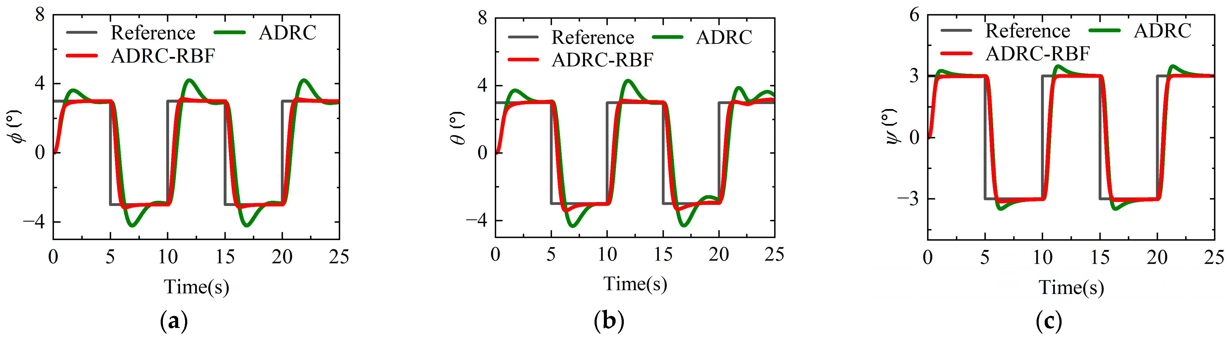
- The attitude control system of the quad tiltrotor UAV is constructed by a combined ADRC-RBF controller. Under the condition of external disturbance, the attitude control system can stabilize the aircraft, and the anti-disturbance performance can be significantly improved. At the same time, it can realize the smooth transition and flight of the attitude in the full-flight mode.
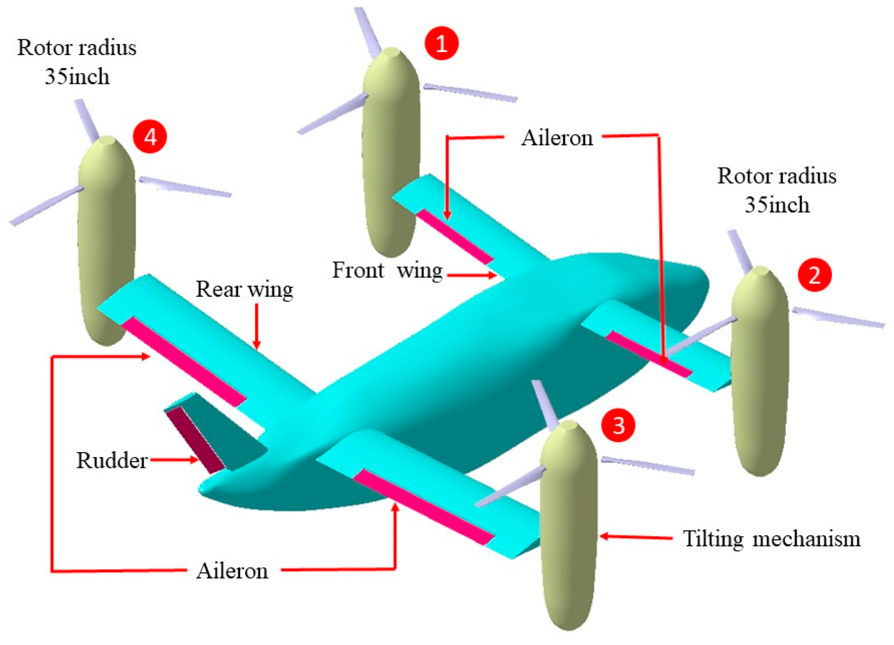
2. Quad Tiltrotor UAV Modeling
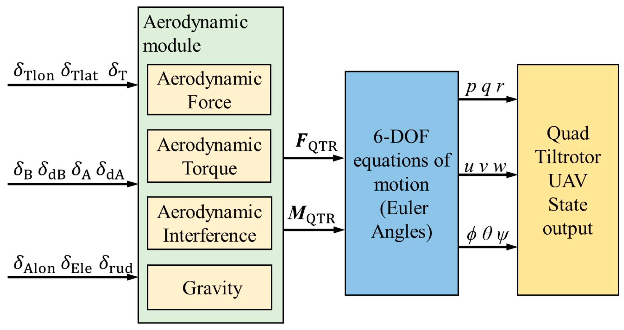
2.1. Flight Dynamics Model
2.2. Manipulation Strategy and Control Allocation
3. ADRC-RBF Adaptive Controller
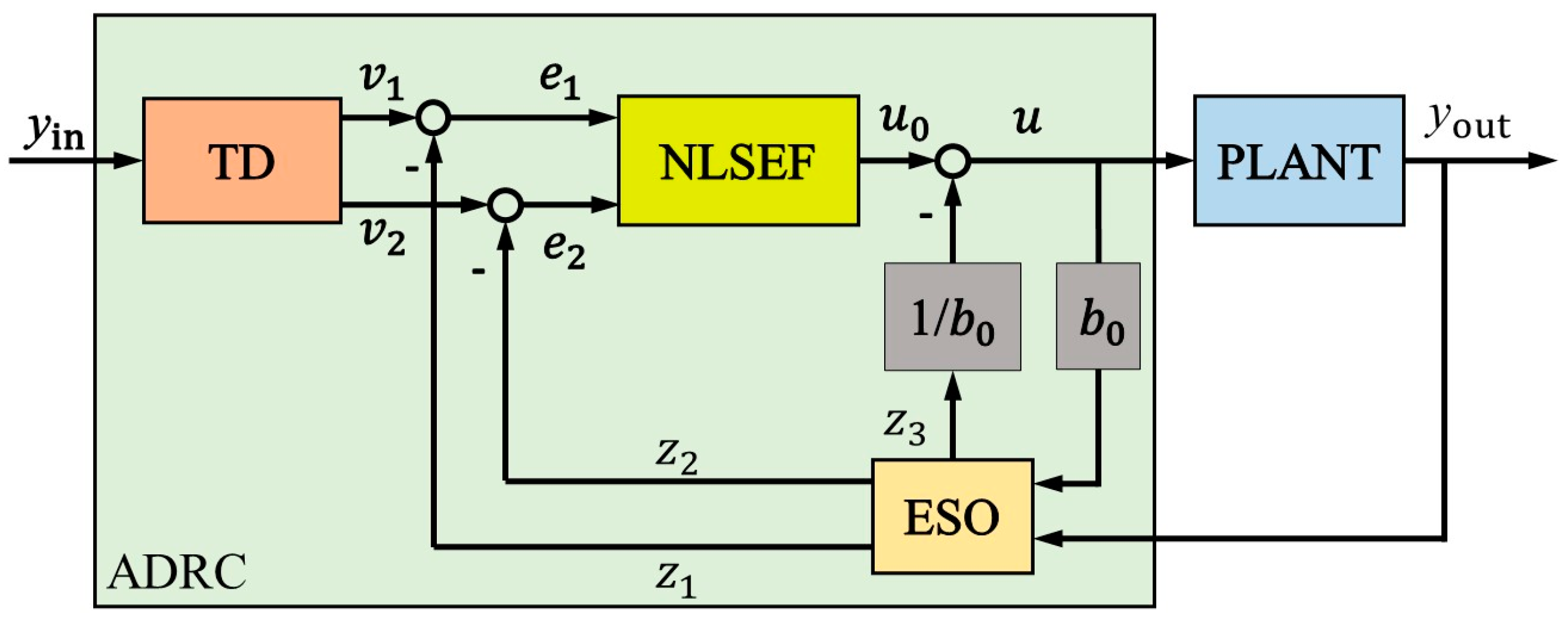
3.1. Structure of the ADRC Controller
3.1.1. Tracking Differentiator (TD)
3.1.2. Extended State Observer (ESO)
3.1.3. Nonlinear State Error Feedback (NLSEF)
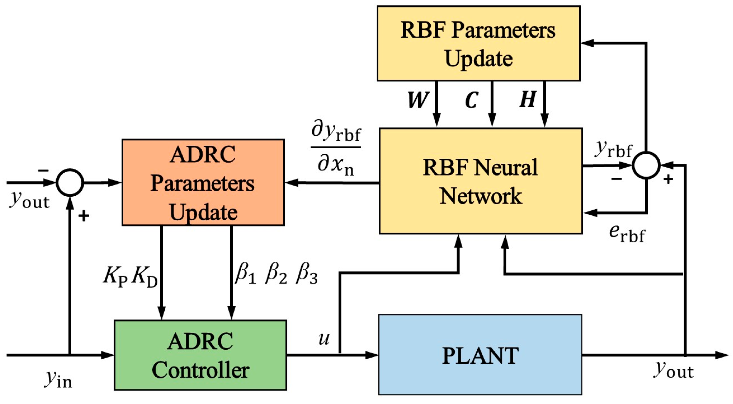
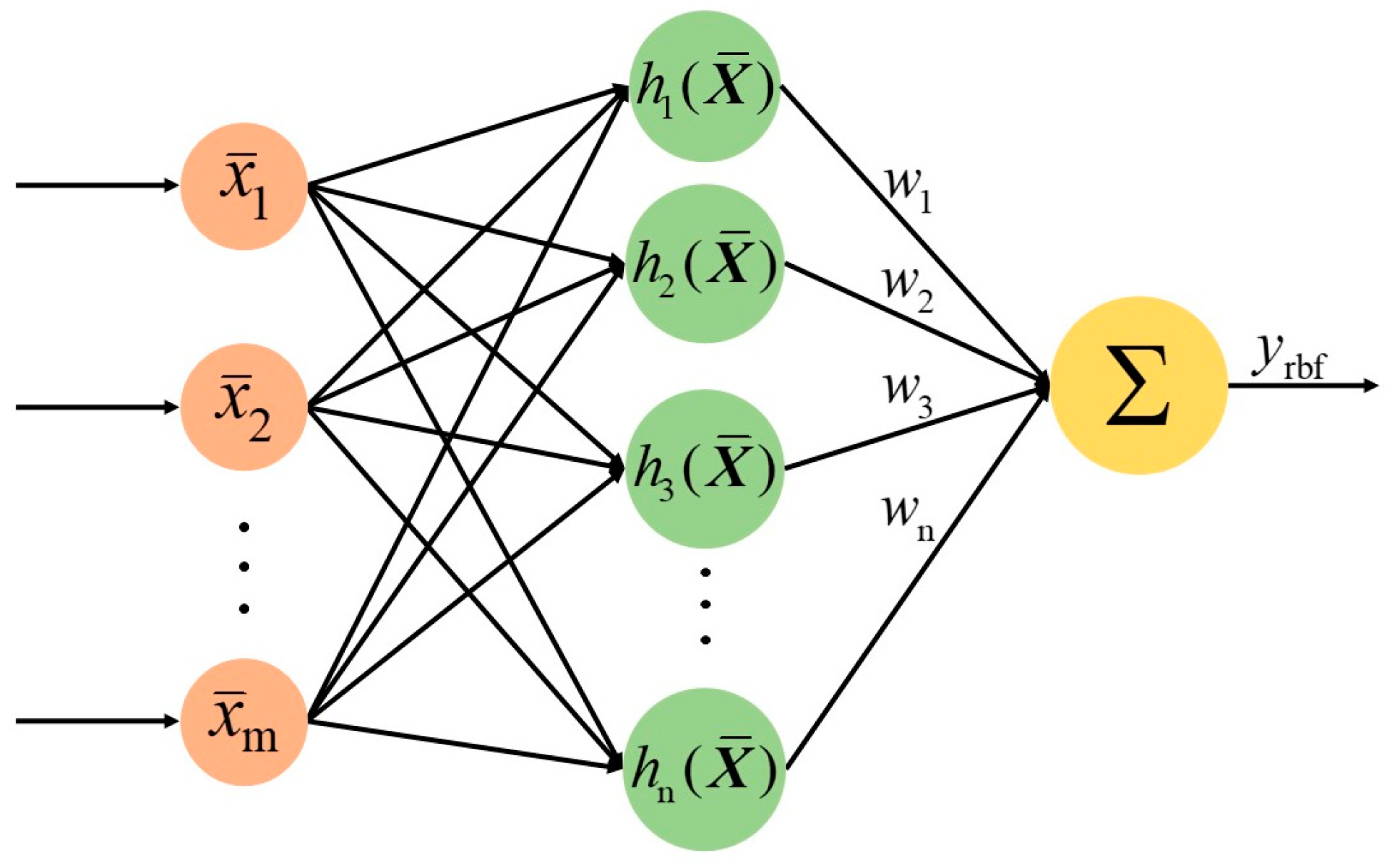
3.2. RBF Neural Network
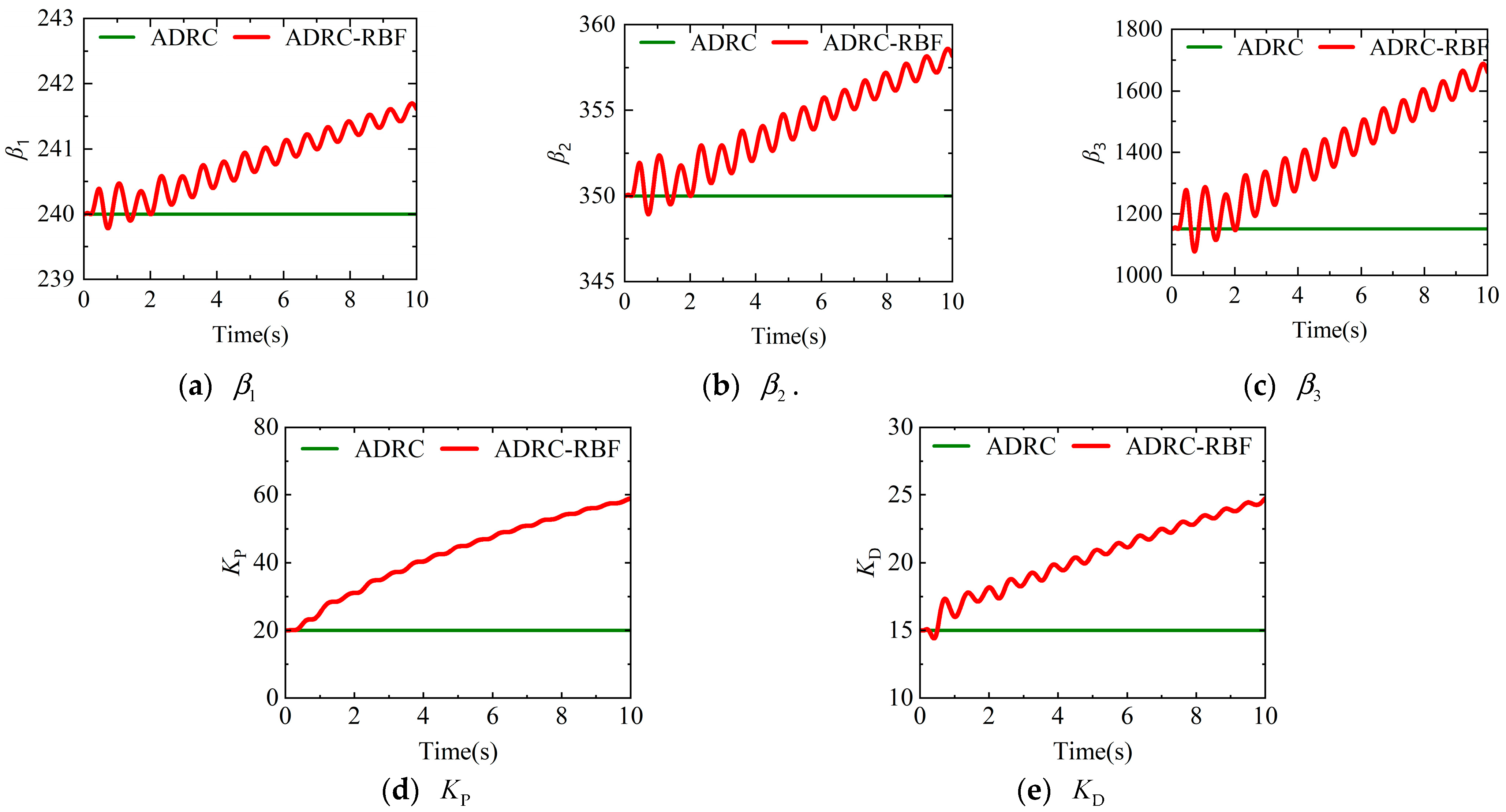
3.3. ADRC Parameter Update
- (a)
- Initialize the ADRC neural network parameters and RBF neural network parameters, set the simulation duration , start the system operation, and then proceed to step b.
- (b)
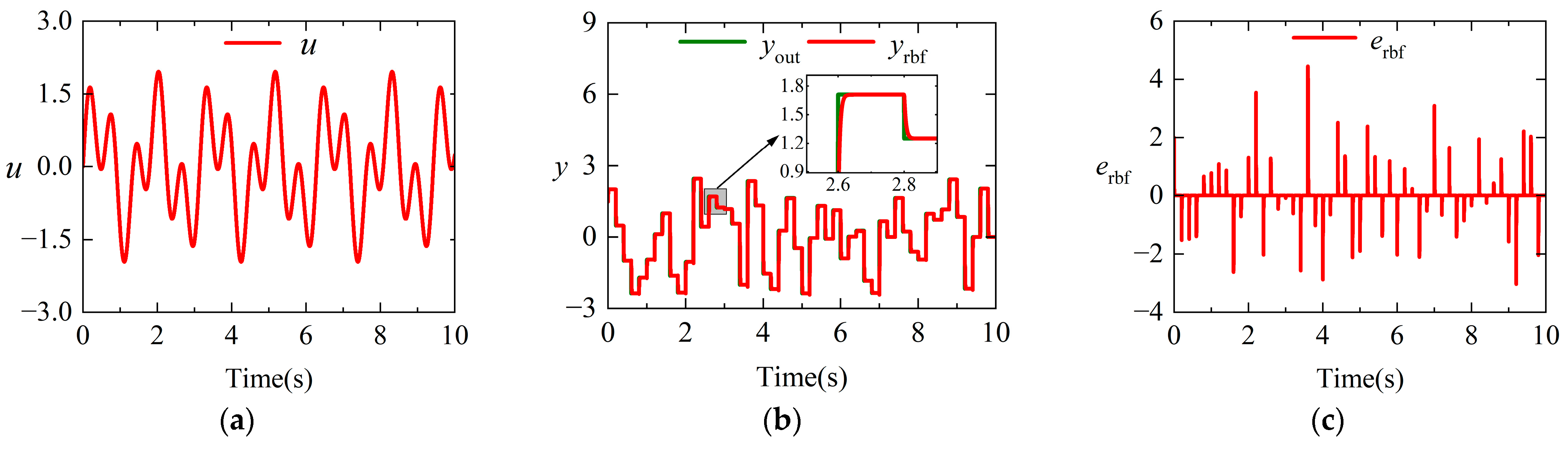
- At time , acquire the controlled system’s control input variable , state output variable , and RBF neural network identification error . Then, the RBF neural network carries out forward propagation to compute the neural network output variable and the controlled system’s Jacobian information , then proceeds to step c.
- (c)
- Determine whether the system operation time satisfies the condition . If the condition is satisfied, proceed to step d; otherwise execute step g.
- (d)
- The RBF neural network executes back propagation to compute increments for the updatable parameters, updates parameters , , and in the neural network based on Equation (19), then proceeds to step e.
- (e)
- Obtain the output response error of the controlled system, and determine whether the system’s output state error satisfies the condition . If the condition is satisfied, proceed to step b for the next iteration; if not satisfied, proceed to step f.
- (f)
- The output response error of the controlled system, the Jacobian information from the RBF neural network output, and the function of ESO and NLSEF. The ADRC controller parameters are then updated according to Equation (23), after which the process proceeds to step b for the next iteration cycle.
- (g)
- The simulation execution is terminated.
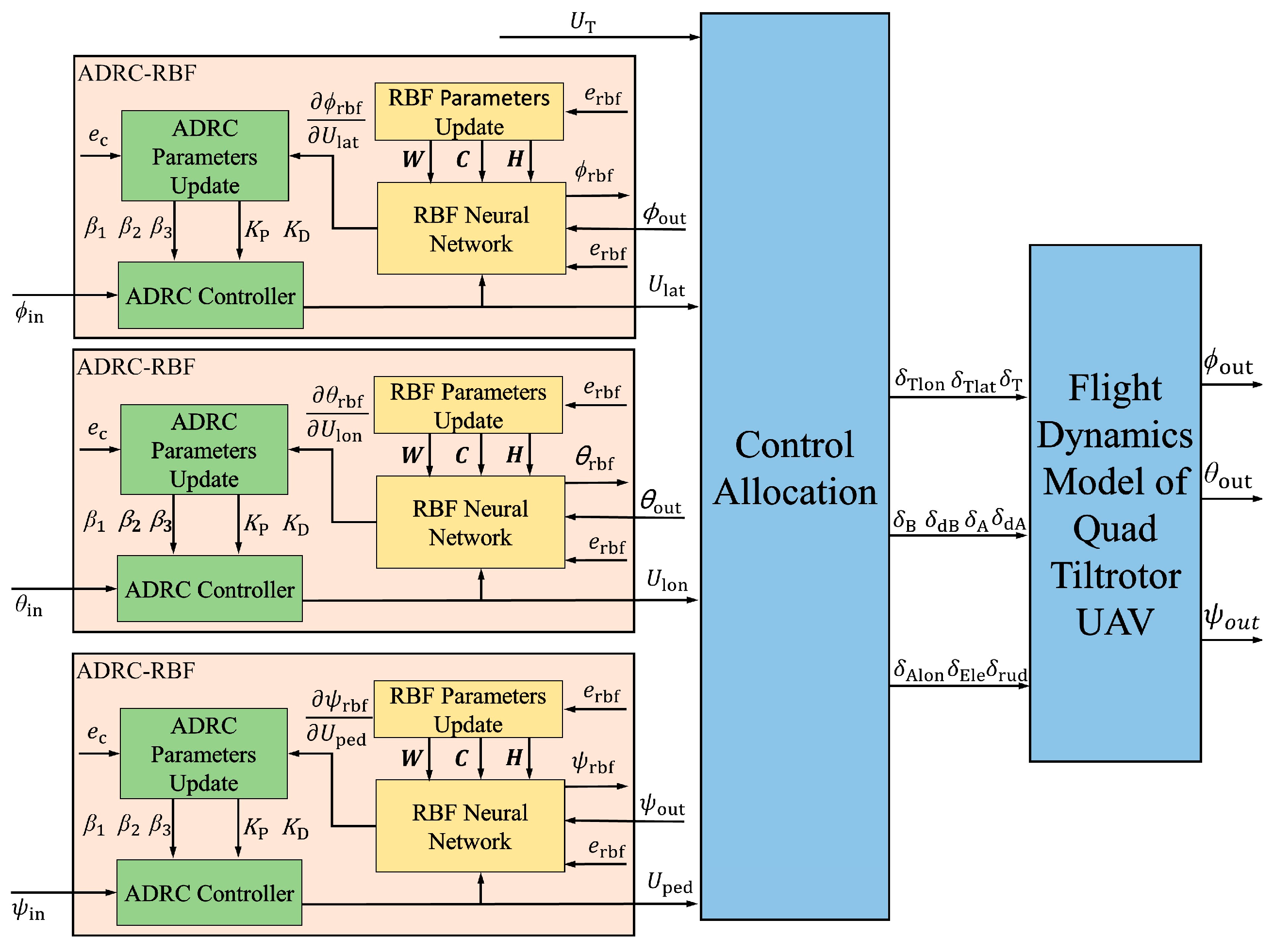
3.4. ADRC-RBF Attitude Control System for Quad Tiltrotor UAV
4. Simulation Results
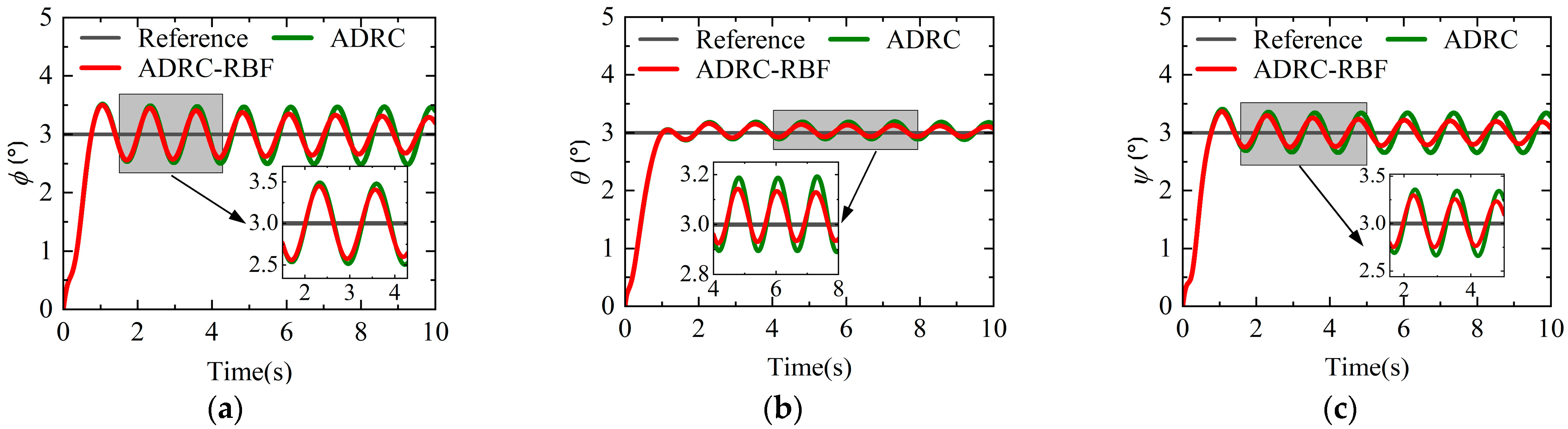
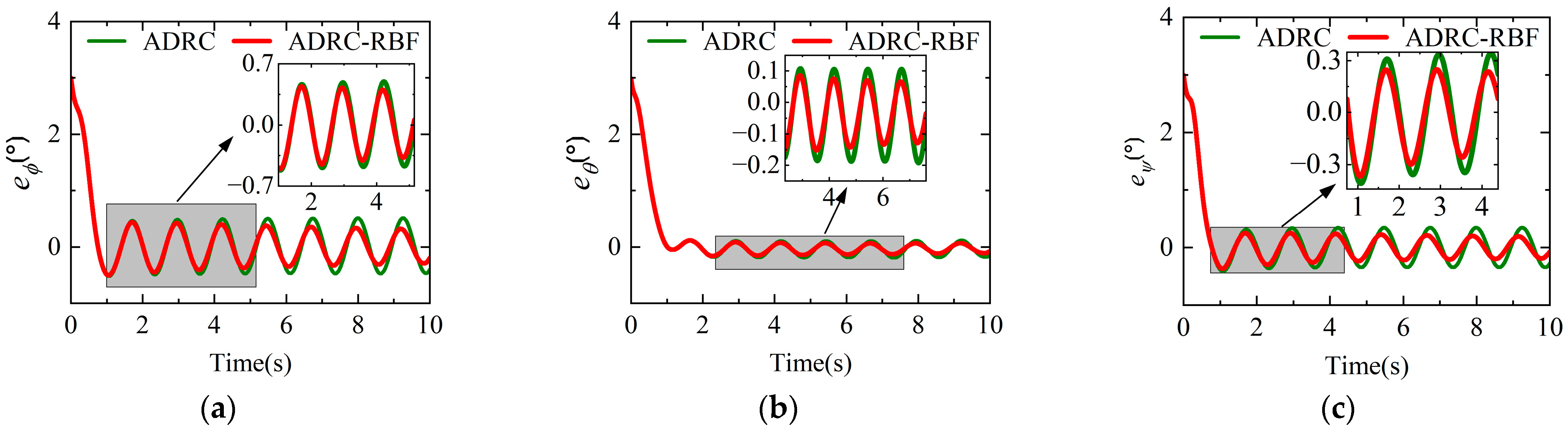
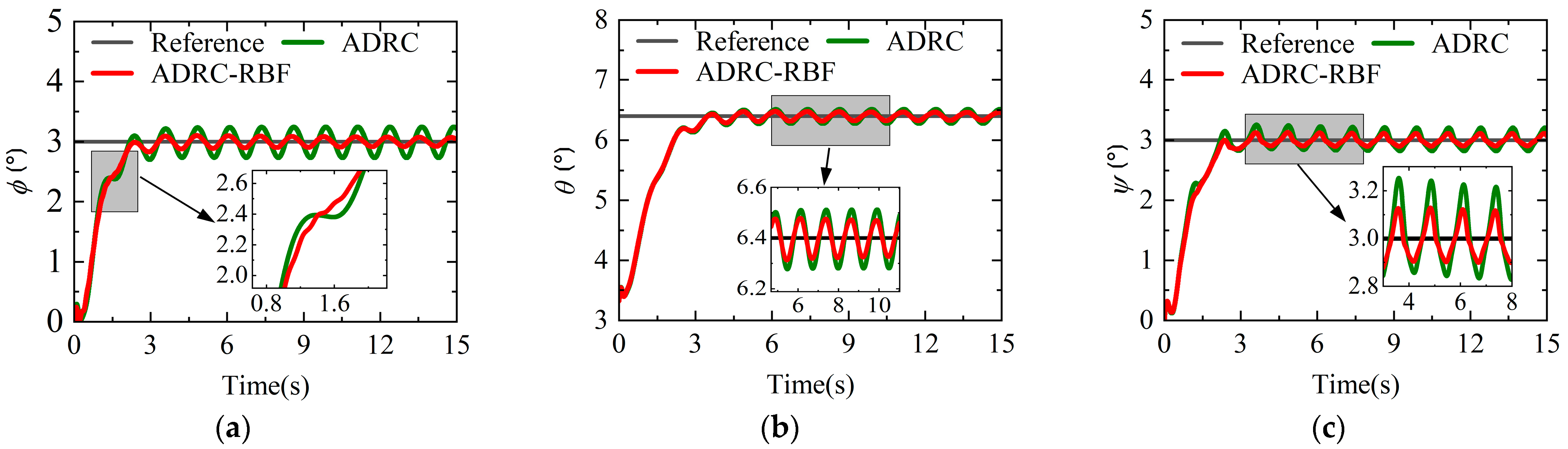
4.1. Helicopter Mode
4.2. Airplane Mode
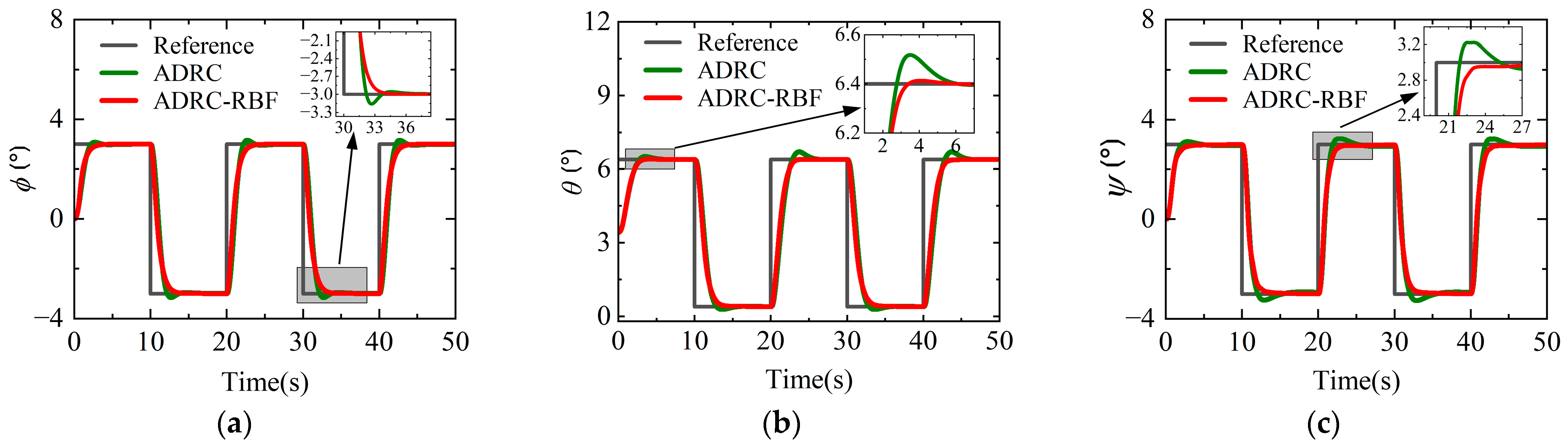
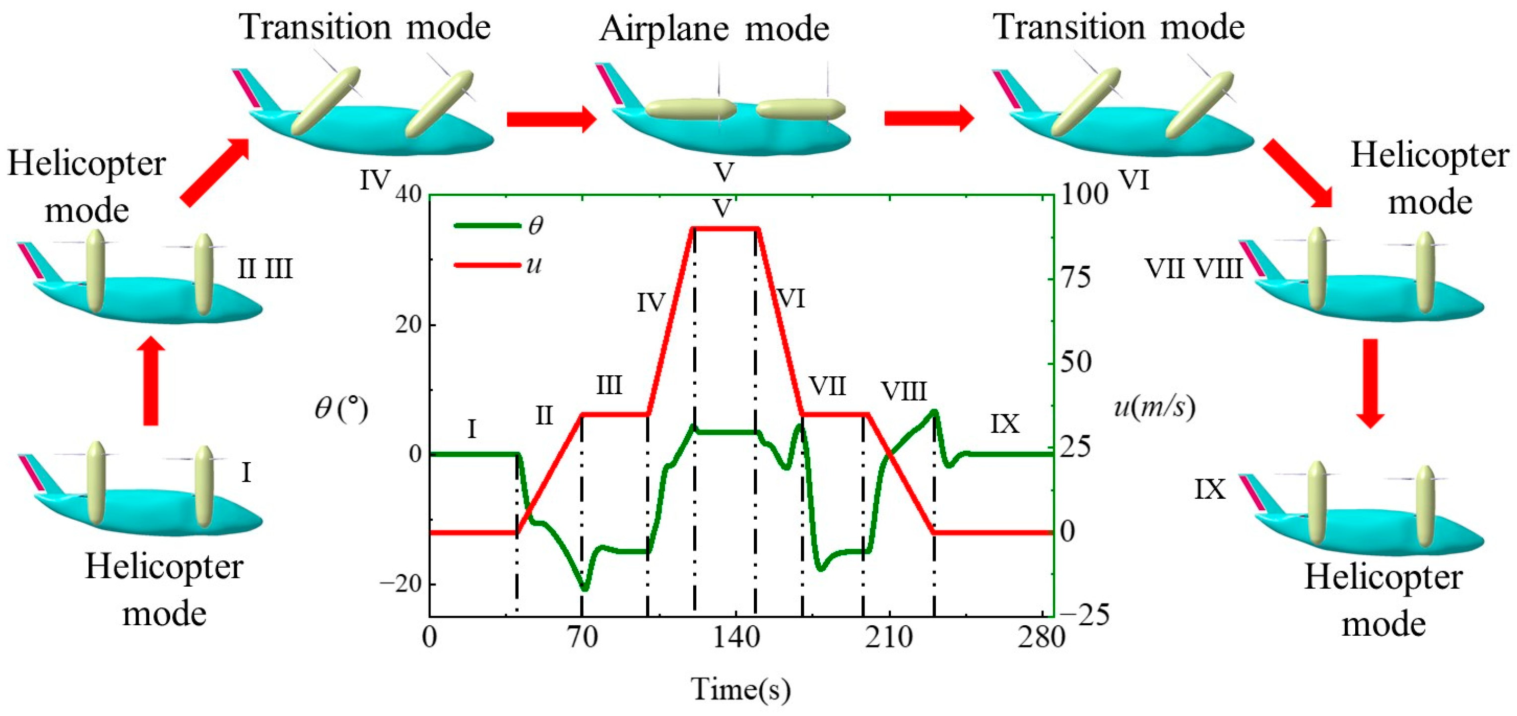
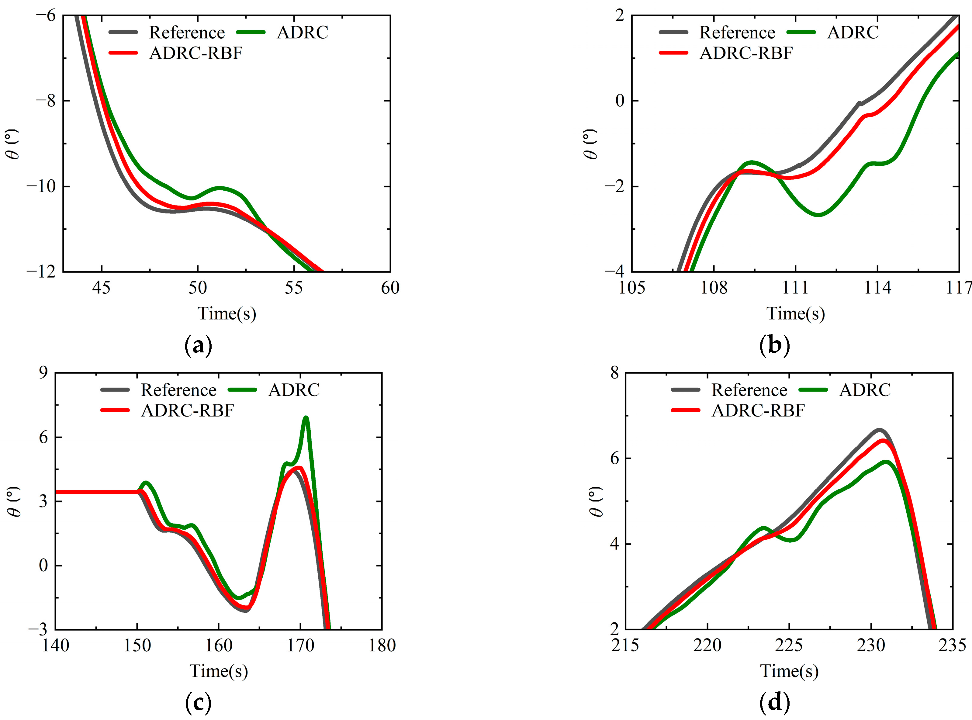
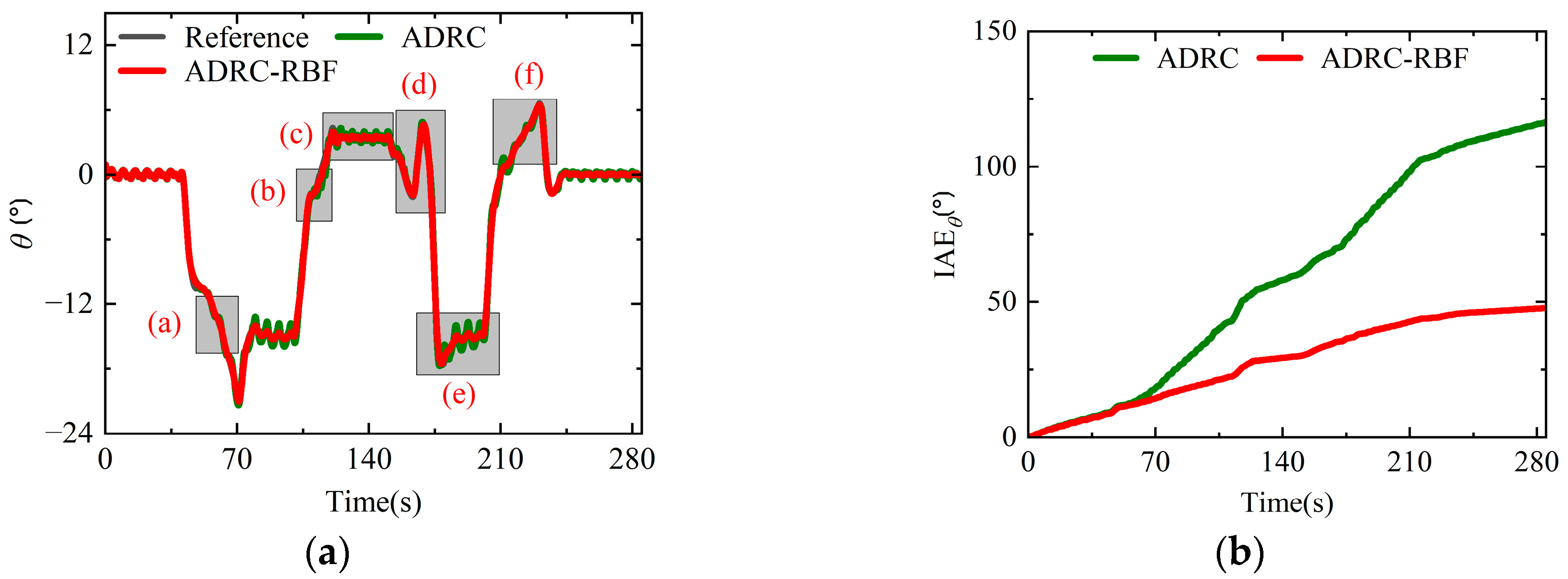
4.3. Full-States Mode
5. Conclusions
Author Contributions
Funding
Data Availability Statement
Conflicts of Interest
Abbreviations
| ADRC | Active Disturbance Rejection Control |
| RBF | Radial Basis Function |
| ESO | Extended State Observer |
| NLSEF | Nonlinear State Error Feedback |
| IAE | Integral Of Absolute Error |
| VTOL | Take-Off and Landing |
| UAV | Unmanned Aerial Vehicle |
| PD | Proportional-Derivative |
| PSO | Particle Swarm Optimization |
| PID | Proportional-Integral-Derivative |
| QRAV | Quadrotor Air Vehicles |
| LQR | Linear Quadratic Regulator |
| INDI | Incremental Nonlinear Dynamic Inversion |
| MPC | Model Predictive Control |
| NNC | Neural Network-Based Control |
| ANN | Adaptive Neural Network |
| RNN | Recurrent Neural Network |
| TD | Tracking Differentiator |
References
- Chen, Z.H. Based on intelligent attack and defense command technology system for multi-rotor tilting vertical takeoff and landing swarm uavs. In Proceedings of the 2023 IEEE International Conference on E-Business Engineering, Sydney, 4–6 November 2023; pp. 276–280. [Google Scholar]
- Hamrouni, A.; Ghazzai, H.; Menouar, H.; Massoud, Y. Multi-Rotor uavs in crowd management systems: Opportunities and challenges. IEEE Internet Things Mag. 2023, 6, 74–80. [Google Scholar] [CrossRef]
- Rejeb, A.; Rejeb, K.; Simske, S.J.; Treiblmaier, H. Drones for supply chain management and logistics: A review and research agenda. Int. J. Logist. Res. Appl. 2023, 26, 708–731. [Google Scholar] [CrossRef]
- Chen, H.; Lan, Y.; Fritz, B.K.; Hoffmann, W.C.; Liu, S. Review of agricultural spraying technologies for plant protection using unmanned aerial vehicle (UAV). Int. J. Agric. Biol. Eng. 2021, 14, 38–49. [Google Scholar] [CrossRef]
- Joo, S.; Kim, H.; Son, H. Multiobjective design optimization of hybrid-powered multirotors for enhanced endurance and payload capacity. IEEE/ASME Trans. Mechatron. 2024, 30, 1959–1970. [Google Scholar] [CrossRef]
- Sasane, A.; Borkar, S.; Majety, P. Optimizing endurance in fixed wing uavs. In International Conference on Smart Computing and Communication; Springer: Singapore, 2024; pp. 219–229. [Google Scholar]
- Liu, Y.; Wang, Y.; Li, H. Runway-free recovery methods for fixed-wing uavs: A comprehensive review. Drones 2024, 8, 463. [Google Scholar] [CrossRef]
- Rojo-Rodriguez, E.U.; Rojo-Rodriguez, E.G.; Araujo-Estrada, S.A. Design and performance of a novel tapered wing tiltrotor UAV for hover and cruise missions. Machines 2024, 12, 653. [Google Scholar] [CrossRef]
- Liu, Z.Q.; He, Y.; Yang, L. Control techniques of tilt rotor unmanned aerial vehicle systems: A review. Chin. J. Aeronaut. 2017, 30, 135–148. [Google Scholar] [CrossRef]
- Sheng, H.; Zhang, C.; Xiang, Y. Mathematical modeling and stability analysis of tiltrotor aircraft. Drones 2022, 6, 92. [Google Scholar] [CrossRef]
- Tran, S.A.; Lim, J.W. Interactional aerodynamics of the xv-15 tiltrotor aircraft during conversion maneuvers. J. Am. Helicopter Soc. 2022, 67, 56–68. [Google Scholar] [CrossRef]
- Lu, K.; Tian, H.; Zhen, P. Conversion flight control for tiltrotor aircraft via active disturbance rejection control. Aerospace 2022, 9, 155. [Google Scholar] [CrossRef]
- El, G.N.; Mjahed, M.; El, K.A. Particle swarm optimization based proportional-derivative parameters for unmanned tilt-rotor flight control and trajectory tracking. Automatika 2020, 61, 189–206. [Google Scholar]
- Wang, Z.; Yuan, Q.; Zhu, Y. Fast and intelligent Proportional—Integral—Derivative (PID) attitude control of quadrotor and dual-rotor coaxial unmanned aerial vehicles (UAVs) based on all-true composite motion. Drones 2024, 8, 747. [Google Scholar] [CrossRef]
- Elshafei, M.E.A.; Elfeky, M.A.; Saif, A.W.A.A. System and Method for Control of Quadrotor Air Vehicles with Tiltable Rotors. U.S. Patent Application No. 14/269,322, 5 May 2014. [Google Scholar]
- Cheng, X.; Wang, Y.; Zhao, J.; Liu, N. ESO-based fuzzy adaptive control of tiltrotor UAV against wind disturbance. Trans. Inst. Meas. Control. 2025. [Google Scholar] [CrossRef]
- Kumar, T.; Kothari, M.; Bhattacharya, R. H∞ Robust Control of a Quadrotor Biplane Tailsitter UAV. In Proceedings of the AIAA SCITECH 2024 Forum, Orlando, FL, USA, 8–12 January 2024; p. 0318. [Google Scholar]
- Dharmawan, A.; Ashari, A.; Putra, A.E. Translation movement stability control of quad tiltrotor using LQR and LQG. Int. J. Intell. Syst. Appl. 2018, 10, 10–21. [Google Scholar] [CrossRef]
- Liu, S.X.; Lin, Z.H.; Liu, W. Control scheme for transition mode of tiltrotor UAV based on INDI. Acta Aeronaut. Astronaut. Sin. 2024, 45, 236–250. [Google Scholar]
- Bauersfeld, L.; Spannagl, L.; Ducard, G. MPC flight control for a tilt-rotor VTOL aircraft. IEEE Trans. Aerosp. Electron. Syst. 2021, 57, 2395–2409. [Google Scholar] [CrossRef]
- Dalwadi, N.; Deb, D.; Kothari, M. Disturbance observer-based backstepping control of tail-sitter UAVs. Actuators 2021, 10, 119. [Google Scholar] [CrossRef]
- Ducard, G.; Carughi, G. Neural network design and training for longitudinal flight control of a tilt-rotor hybrid vertical takeoff and landing unmanned aerial vehicle. Drones 2024, 8, 727. [Google Scholar] [CrossRef]
- Han, J.Q. From PID to active disturbance rejection control. IEEE Trans. Ind. Electron. 2009, 56, 900–906. [Google Scholar] [CrossRef]
- Gao, J.; Gao, S.; Chen, Y. Research on Anti-wind Disturbance Controller of Tiltrotor UAV Based on ADRC. In Proceedings of the 2024 IEEE 4th International Conference on Data Science and Computer Application (ICDSCA), Dalian, China, 22–24 November 2024; pp. 842–848. [Google Scholar]
- Deng, B.; Xu, J.; Yuan, X. Active disturbance rejection flight control and simulation of unmanned quad tilt rotor eVTOL based on adaptive neural network. Drones 2024, 8, 560. [Google Scholar] [CrossRef]
- Ren, B.W.; Du, S.L.; Cui, Z.Z. High-precision trajectory tracking control of helicopter based on ant colony optimization-slime mould algorithm. Chin. J. Aeronaut. 2025, 38, 103172. [Google Scholar] [CrossRef]
- Shen, S.; Xu, J. Attitude active disturbance rejection control of the quadrotor and its parameter tuning. Int. J. Aerosp. Eng. 2020, 2020, 8876177. [Google Scholar] [CrossRef]
- Liu, N.J.; Cai, Z.H.; Jiang, Z. Predictor-based model reference adaptive roll and yaw control of a quad-tiltrotor UAV. Chin. J. Aeronaut. 2020, 33, 282–295. [Google Scholar] [CrossRef]
- Saif, A.W.A. Feedback linearization control of quadrotor with tiltable rotors under wind gusts. Int. J. Adv. Appl. Sci. 2017, 4, 150–159. [Google Scholar] [CrossRef]
- Wang, Z.; Li, J.; Duan, D. Manipulation strategy of tilt quad rotor based on active disturbance rejection control. J. Aerosp. Eng. 2020, 234, 573–584. [Google Scholar] [CrossRef]
- Elfeky, M.; Elshafei, M.; Saif, A.W.A.; Al-Malki, M.F. Quadrotor with tiltable rotors for manned applications. In Proceedings of the 2014 IEEE 11th International Multi-Conference on Systems, Castelldefels, Spain, 11–14 February 2014; pp. 1–5. [Google Scholar]
- Hua, C.; Wang, K.; Chen, J.N. Tracking differentiator and extended state observer-based nonsingular fast terminal sliding mode attitude control for a quadrotor. Nonlinear Dyn. 2018, 94, 343–354. [Google Scholar] [CrossRef]
- Liang, Z.; Fan, L.; Wen, G.; Xu, Z. Design, modeling, and control of a composite tilt-rotor unmanned aerial vehicle. Drones 2024, 8, 102. [Google Scholar] [CrossRef]
- Sharkawy, A.N. Principle of neural network and its main types. J. Adv. Appl. Comput. Math. 2020, 7, 8–19. [Google Scholar] [CrossRef]
- Haykin, S. Neural Networks: A Comprehensive Foundation; Prentice Hall: Upper Saddle River, NJ, USA, 1994; pp. 409–412. [Google Scholar]
- Ding, H.; Liu, S.; Wang, Z. An ADRC parameters self-tuning controller based on RBF neural network for multi-color register system. Machines 2023, 11, 320. [Google Scholar] [CrossRef]
- Jie, L.; Yuanqing, X. On stability analysis of nonlinear ADRC-based control system with application to inverted pendulum problems. J. Syst. Eng. Electron. 2024, 35, 1563–1573. [Google Scholar]
- Li, J.; Qi, X.; Xia, Y. Research on linear/nonlinear active disturbance rejection switching control method. Acat Autom. Sin. 2016, 42, 202–212. [Google Scholar]


| Parameter | Unit | Value |
|---|---|---|
| Quality | kg | |
| Rotor speed | ||
| Numbers of blades | ||
| Length of front wing | ||
| Length of rear wing | ||
| Parameter | (°) | Value | Parameter | (°) | Value |
|---|---|---|---|---|---|
| Parameter | ADRC/ADRC-RBF (No Disturbance) | ADRC/ADRC-RBF (Disturbance) |
|---|---|---|
| Parameter | ADRC/ADRC-RBF (No Disturbance) | ADRC/ADRC-RBF (Disturbance) |
|---|---|---|
| Parameter | ADRC/ADRC-RBF (No Disturbance) | ADRC/ADRC-RBF (Disturbance) |
|---|---|---|
Disclaimer/Publisher’s Note: The statements, opinions and data contained in all publications are solely those of the individual author(s) and contributor(s) and not of MDPI and/or the editor(s). MDPI and/or the editor(s) disclaim responsibility for any injury to people or property resulting from any ideas, methods, instructions or products referred to in the content. |
© 2025 by the authors. Licensee MDPI, Basel, Switzerland. This article is an open access article distributed under the terms and conditions of the Creative Commons Attribution (CC BY) license (https://creativecommons.org/licenses/by/4.0/).
Share and Cite
He, J.; Ren, B.; Xu, Y.; Zhao, Q.; Du, S.; Wang, B. Neural Network Adaptive Attitude Control of Full-States Quad Tiltrotor UAV. Aerospace 2025, 12, 684. https://doi.org/10.3390/aerospace12080684
He J, Ren B, Xu Y, Zhao Q, Du S, Wang B. Neural Network Adaptive Attitude Control of Full-States Quad Tiltrotor UAV. Aerospace. 2025; 12(8):684. https://doi.org/10.3390/aerospace12080684
Chicago/Turabian StyleHe, Jiong, Binwu Ren, Yousong Xu, Qijun Zhao, Siliang Du, and Bo Wang. 2025. "Neural Network Adaptive Attitude Control of Full-States Quad Tiltrotor UAV" Aerospace 12, no. 8: 684. https://doi.org/10.3390/aerospace12080684
APA StyleHe, J., Ren, B., Xu, Y., Zhao, Q., Du, S., & Wang, B. (2025). Neural Network Adaptive Attitude Control of Full-States Quad Tiltrotor UAV. Aerospace, 12(8), 684. https://doi.org/10.3390/aerospace12080684