Abstract
The aerodynamic optimization of airfoil shapes remains a critical research area for enhancing aircraft performance under various flight conditions. In this study, the RAE 2822 airfoil was selected as a benchmark case to investigate and compare the effectiveness of surrogate-based methods under an Efficient Global Optimization (EGO) framework and an adjoint-based approach in both single-point and multi-point optimization settings. Prior to optimization, the computational fluid dynamics (CFD) model was validated against experimental data to ensure accuracy. For the surrogate-based methods, Kriging (KRG), Kriging with Partial Least Squares (KPLS), Gradient-Enhanced Kriging (GEK), and Gradient-Enhanced Kriging with Partial Least Squares (GEKPLS) were employed. In the single-point optimization, the GEK method achieved the highest drag reduction, outperforming other approaches, while in the multi-point case, GEKPLS provided the best overall improvement. Detailed comparisons were made against existing literature results, with the proposed methods showing competitive and superior performance, particularly in viscous, transonic conditions. The results underline the importance of incorporating gradient information into surrogate models for achieving high-fidelity aerodynamic optimizations. The study demonstrates that surrogate-based methods, especially those enriched with gradient information, can effectively match or exceed the performance of gradient-based adjoint methods within reasonable computational costs.
1. Introduction
Aerodynamic shape optimization has gained increasing attention in complex engineering fields such as aerospace, automotive, and energy industries. Although aerodynamic optimization can be computationally expensive due to the evaluation of cost functions, it is often preferred because it leads to more efficient systems overall. Methods, techniques, and algorithms developed for this purpose are primarily driven by leading research institutes and industrial R&D centers. Today, these approaches are widely adopted and continue to attract interest from a growing number of users, companies, and researchers.
The AIAA Aerodynamic Design Optimization Discussion Group (ADODG) [1] proposes various benchmark cases with different flow conditions to guide researchers working in aerodynamic optimization. In this study, the results and performance of a surrogate-based optimization framework are investigated for the ADODG’s Test Case 2, which focuses on drag minimization of the RAE 2822 airfoil under transonic flow conditions. One of the main reasons for selecting surrogate-based methods is their high potential for application in aerospace engineering, combined with their flexibility and adaptability.
Table 1 and Table 2 present literature reviews on the single-point optimization of the RAE 2822 airfoil, focusing based on gradient-based and gradient-free methods, respectively. Similarly, Table 3 presents a literature review on the multi-point optimization of the RAE 2822 airfoil. In these tables, references that strictly follow the ADODG-defined test case setup are marked as “Yes”, while those adopting different conditions are marked as “No” (i.e., although the conditions of these studies are slightly different than ADODG Test Case 2, they do not reflect the exact conditions as this case). Furthermore, these tables are updated with the corresponding results and the achieved improvements, as will be discussed in the Results section.

Table 1.
Single-point gradient-based optimization literature review for RAE 2822 airfoil.
Table 2.
Single-point gradient-free optimization literature review for RAE 2822 airfoil.
Table 3.
Multi-point optimization literature review for RAE 2822 airfoil.
Adjoint-based methods have traditionally been the backbone of gradient-based aerodynamic shape optimization due to their ability to compute gradients efficiently, particularly when dealing with a large number of design variables. This capability has made them the preferred approach in several studies focusing on the RAE 2822 airfoil, especially with the ADODG Test Case 2. Numerous studies have utilized the SU2 open-source CFD suite in conjunction with adjoint solvers [3,4,8,9], while others have applied industrial solvers such as elsA [5]. Despite their theoretical elegance, these methods are not without limitations. Challenges such as the sensitivity of gradient accuracy to shock-separation interactions [6], difficulties in optimization convergence due to non-unique flow solutions [7], and the complexity of robust parameterization [5] have been frequently reported. For instance, Poole et al. [2] employed a gradient-based FSQP optimizer with a control point-based deformation strategy and demonstrated reasonable performance with a modest number of design variables. Yang et al. [3] compared two different geometry parameterization approaches and highlighted their insensitivity to parameterization settings. Abergo [4] presented a robust adjoint-based optimization in his thesis and acknowledged that while the final result was not the best, it was comparable to existing benchmarks. Other works have echoed similar concerns: Carrier et al. [5] emphasized that achieving both robustness and efficiency in adjoint methods is nontrivial and often dependent on best-practice consolidation; He et al. [6] noted sensitivity to shock-induced instabilities, while Lee et al. [7] demonstrated that mesh resolution and deformation method can significantly impact convergence behavior. These accumulated challenges underscore the growing interest in alternative strategies such as surrogate-based optimization methods. In contrast to adjoint techniques, surrogate models—particularly those embedded in global optimization frameworks—offer robustness against numerical instabilities, flexibility in handling multi-fidelity or multi-point problems, and a natural capacity for global exploration without requiring gradient information. The gradient-free methods require a lot of computational resources when scanning globally. This is indeed a general disadvantage of gradient-free methods. The present study leverages this potential by adopting an EGO [22] framework enhanced with gradient-informed surrogate models to address the limitations encountered in adjoint-based approaches, especially in transonic, multi-point aerodynamic design.
Surrogate-based optimization strategies have increasingly been explored as robust alternatives to gradient-based methods, especially in aerodynamic shape optimization problems involving costly CFD simulations. These methods aim to reduce computational expenses by approximating the true objective function using inexpensive surrogate models. Notably, Zhang et al. [10] compared a multi-round surrogate-based optimization strategy with adjoint-based methods for the RAE 2822 airfoil and demonstrated competitive performance. Neural-network-based surrogate approaches have also gained attention: Nagawkar et al. [11] utilized multifidelity neural networks and further enhanced them through gradient-enriched versions (GENN). While promising, such black-box surrogates often lack interpretability and can suffer from instability in high-gradient regions. A more systematic class of approaches, centered on Kriging and Gaussian Process Regression (GPR), have formed the foundation of many EGO frameworks. For example, Wang et al. [12], Zhang et al. [13], and Koratikere et al. [20] employed EGO variants, often coupled with Expected Improvement (EI) criteria or neural network surrogates. However, standard Kriging models can face challenges when handling high-dimensional (high number of design variables) or ill-conditioned design spaces, and typically lack built-in mechanisms to account for gradient information. To mitigate these issues, more advanced surrogate formulations have been proposed. Xue et al. [15] incorporated automatic kernel construction to adaptively improve GPR models, while Özkaya and Gauger [18] proposed a gradient-informed aggregation strategy. Still, many of these methods remain limited in their ability to generalize across multi-point or high-fidelity design requirements, or to effectively integrate gradient data in a stable manner. In contrast, the present study adopts and systematically compares four advanced surrogate models KRG, KPLS, GEK, and GEKPLS within an EGO framework. These models offer complementary strengths: KPLS enhances Kriging’s scalability in high-dimensional spaces through dimensionality reduction; GEK exploits available gradient data to increase local accuracy; and GEKPLS combines both strategies for improved robustness and convergence efficiency. By incorporating these advanced surrogates into a unified optimization framework, this study aims to bridge the gap between global exploration and local refinement, addressing limitations observed in earlier surrogate-based efforts. This structured approach forms the cornerstone of the proposed methodology and highlights the novelty of the current contribution in the aerodynamic shape optimization of transonic airfoils.
While surrogate-based methods have shown promise in single-point aerodynamic optimization, their extension to multi-point scenarios remains relatively underexplored, largely due to increased modeling complexity, conflicting design requirements, and the need for global consistency across multiple operating conditions. Only a limited number of studies have attempted to address the multi-point optimization of the RAE 2822 airfoil. For instance, Koratikere and Leifsson [20] extended their cEGO-based single-point framework to accommodate three flight regimes by varying the Mach number, representing takeoff, cruise, and landing. Their approach remained confined to a neural-network surrogate and did not explicitly address the scalability and generalizability issues associated with more physically-informed surrogate models. Nagawkar et al. [14], on the other hand, employed manifold mapping under Euler assumptions to reduce computational costs, but the lack of viscous effects and gradient exploitation limits the practical applicability and local accuracy of the resulting designs. Similarly, Toal and Keane [21] applied Kriging models to multi-point problems, but scalability with respect to increasing design variables and the integration of gradient information remained unresolved.
The design framework employed in this study incorporates EGO [23] along with EI as the infill sampling criterion [23,24]. Initially, the surrogate model within EGO was integrated with the Kriging method [25], one of the most frequently encountered surrogate models in literature [21,26,27]. However, there are concerns about the performance limitations of Kriging, and several studies aim to address and improve its capabilities [28,29]. Bouhlel et al. [30] proposed the Kriging with Partial Least Squares (KPLS) method, integrating PLS with Kriging to enable optimization with higher numbers of design variables, although their validation was limited to mathematical analytic functions.
Despite its advantages, Kriging has been reported to suffer from issues such as slow convergence and limited accuracy [31]. To improve Kriging’s accuracy, GEK [32] was developed, which incorporates gradient information during surrogate model construction. Finally, Bouhlel et al. [33] proposed the Gradient-Enhanced Kriging with Partial Least Squares (GEKPLS) method, addressing challenges associated with inverting large gradient-augmented datasets by combining the benefits of KPLS and GEK. Although still relatively new and less widely adopted in the literature, GEKPLS theoretically combines the advantages of PLS in reducing the number of Kriging hyperparameters and the enhanced accuracy of GEK through gradient information, making it particularly effective for high-dimensional optimization problems.
In light of the limitations observed in both adjoint-based and surrogate-based aerodynamic optimization approaches—particularly in the context of multi-point problems—this study aims to advance the state-of-the-art by developing and evaluating a unified surrogate-based optimization framework with gradient-enhancement. The framework is applied to the RAE 2822 airfoil for both single-point and multi-point transonic viscous flow conditions. The proposed approach systematically integrates advanced surrogate models with robust geometry parameterization and CFD-based gradient information, offering a scalable and physically grounded design methodology. The novelty and key contributions of this study can be summarized as follows:
- Gradient-informed surrogate modeling: Implementation and comparison of four surrogate types—KRG, KPLS, GEK, and the combined GEKPLS under a single framework—to enable more accurate local approximations and global search.
- Multi-point optimization in viscous transonic regime: Extension of the surrogate-based EGO framework to a multi-point setup, addressing multiple operating conditions with viscous CFD, a task rarely attempted in the literature.
- Consistent parameterization and FFD-based shape control: Use of a stable and flexible geometry control mechanism compatible with high-fidelity solvers, ensuring robustness across diverse flight regimes.
- Systematic evaluation and benchmarking: Direct comparison of surrogate strategies under identical CFD settings and design objectives, offering practical insights into model performance and reliability in realistic aerodynamic scenarios.
- These contributions not only address key gaps in previous works but also demonstrate the feasibility of reliable and efficient aerodynamic shape optimization in complex, multi-point design environments.
- Extensive comparisons with benchmark literature results are provided to validate the methodology and highlight the competitiveness of the proposed surrogate-assisted strategies in drag reduction.
2. Methods
2.1. FFD Box View and Mesh Deformation
An important step in aerodynamic shape optimization is the parametrization of the design to be modified. Once the boundary of the design is mathematically represented by a set of parameters using various methods, these parameters are then passed to the subsequent steps of the optimization process. Free-Form Deformation (FFD) is the shape parametrization technique employed in this study and is frequently used in aerodynamic shape optimization due to the flexibility it provides [34,35].
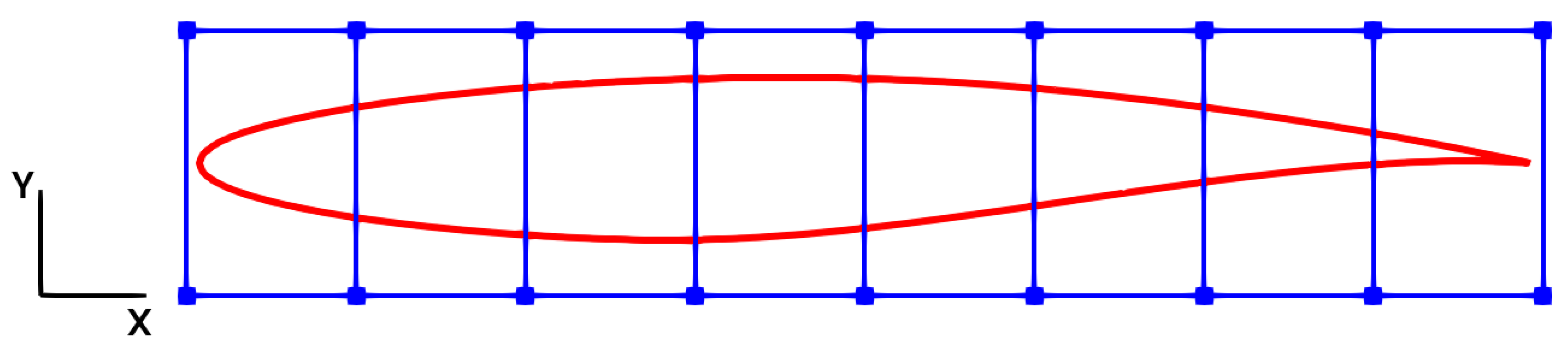
More specifically, FFD allows smooth and continuous deformations of the surface by manipulating a set of control points placed around the design boundary. This enables the generation of a wide variety of shape modifications while maintaining control over the number of design parameters. An illustration of these details can be seen in Figure 1. In this figure, the baseline geometry of an airfoil and its surrounding FFD box are depicted. The FFD box includes 18 control points, shown in blue, which are referred to as either control points or design variables, while the baseline geometry is highlighted in red. Although the design variables are, in principle, allowed to move in both the x and y directions, in this study their motion is restricted to the y direction, allowing only upward and downward movements. In this particular case, since the all corners of the FFD box are defined as fixed, in total there are 14 design variables.

Figure 1.
A two dimensional FFD box (blue lines) example around baseline geometry (red line).
Following shape modification via FFD, the volume mesh surrounding and covering the design boundary must also be deformed to ensure consistency between the shape and the mesh. This deformation is critical for maintaining the accuracy of the aerodynamic analysis. In this method, where an inverse volume-based mesh deformation technique is adopted, the computational mesh is modeled as a fully elastic solid, and the linear elasticity equation is solved over this domain. The modulus of elasticity for each cell in the mesh is assigned inversely proportional to its volume, such that smaller cells experience less deformation and larger cells undergo greater deformation.
2.2. Surrogate-Based Methods
2.2.1. Kriging (KRG)
Kriging is a powerful surrogate-based modeling technique commonly used to approximate unknown functions, particularly in computationally expensive engineering design problems. The Kriging model provides not only predictions of function values but also an estimate of the uncertainty associated with these predictions. These capabilities offer a significant advantage when selecting new sampling points. The Kriging model [36] can be expressed as shown in Equation (1).
where is the predicted function value, is a constant mean, and is a Gaussian process with zero mean, constant variance, and a specified covariance structure. The correlation between two sample points is generally defined as shown in Equation (2).
where d is the number of design variables, and are the correlation parameters. The prediction at a new point is calculated as shown in Equation (3).
where is the correlation vector between and the existing samples, is the correlation matrix among the existing samples, is the vector of existing outputs, and is a vector consisting entirely of ones. The predicted variance (uncertainty) is expressed as shown in Equation (4).
where is the process variance estimated by the model. The Kriging model is an efficient tool for achieving high accuracy with a low number of samples and is widely used in various fields such as optimization, design exploration, and uncertainty quantification.
2.2.2. Kriging with Partial Least Squares (KPLS)
The Kriging with Partial Least Squares (KPLS) method is an enhanced approach developed to overcome the performance challenges faced by classical Kriging models in high-dimensional problems. Specifically, when the design space is highly dimensional and the dataset is relatively small, the accuracy and computational cost of traditional Kriging models can be significantly impacted [33]. The KPLS method employs the Partial Least Squares (PLS) algorithm to identify the most influential combinations of input variables, similar to principal component analysis. As a result, the Kriging model is constructed over a lower-dimensional subspace rather than the original high-dimensional space [30]. In the PLS step, the latent directions that maximize the covariance between the input and output variables are identified, and subsequently, the Kriging model is built upon this reduced-dimensional representation. With the KPLS method, the number of hyperparameters is reduced from d to h, where , providing significant improvement in computational time. As shown in Equation (5), this reduction can be easily observed when compared to the formulation described in Equation (2).
The general structure of the KPLS algorithm consists of the following steps [30]:
- Input and output data are collected.
- The input space is projected onto a lower-dimensional space by applying the PLS method.
- A Kriging model is constructed on the reduced input space.
This approach enhances model accuracy while reducing the computational burden in high-dimensional problems. It has proven to be particularly effective in complex engineering applications such as aerodynamic shape optimization. In this study, alongside the conventional Kriging method, the KPLS method is also investigated, and its results are incorporated into the optimization problem.
2.2.3. Gradient-Enhanced Kriging (GEK)
The Gradient-Enhanced Kriging (GEK) model aims to construct a more accurate surrogate model by incorporating not only function values but also gradient information into the modeling process, unlike classical Kriging [37]. In engineering applications, gradients obtained through techniques such as adjoint methods or automatic differentiation (AD) can significantly improve the model’s predictive accuracy [38]. The primary advantage of GEK is its ability to achieve high accuracy even with a limited number of sample points, as gradient information provides direct insight into the local behavior of the function, thereby enabling the model to better learn its global characteristics [39]. In the GEK model, for input variables and an objective function , the dataset can be extended as shown in Equation (6).
where represents the d-dimensional gradient vector of the function.
The GEK correlation matrix R consists of three main components: namely, correlations between function values, correlations between function values and gradients, and correlations between gradients.
For instance, the correlation between two points is defined as:
The gradient correlations are derived from the derivatives of the correlation function with respect to the partial derivatives of the function:
where denotes the Kronecker delta function. Consequently, by integrating both the function values and gradient information, the GEK model constructs a richer dataset and typically achieves faster and more accurate convergence compared to the classical Kriging model.
2.2.4. Gradient-Enhanced Kriging with Partial Least Squares (GEKPLS)
The Gradient-Enhanced Kriging with Partial Least Squares (GEKPLS) method leverages the strengths of both GEK and Partial Least Squares (PLS) to address high-dimensional optimization problems that incorporate gradient information [33]. In this approach, a PLS-based projection is first applied to the input space to reduce its dimensionality by emphasizing directions most influential on the objective function and its derivatives [40]. This dimensionality reduction helps overcome the challenges typically associated with high-dimensional surrogate modeling—known as the curse of dimensionality (typically encountered in GEK)—by enabling the construction of more accurate models using fewer sample points. Through the integration of gradient information and dimension reduction techniques, GEKPLS achieves high-fidelity surrogate models for problems with a large number of design variables while maintaining computational efficiency.
2.3. Adjoint Method
In this study, adjoint optimization is performed using the SU2 code. The steps involved in adjoint optimization include: shape parametrization, flow analysis, adjoint solution, gradient computation, and mesh deformation. The Sequential Least Squares Programming (SLSQP) [2] algorithm and a gradient-based optimization method are available in SU2. For the gradient of the selected objective function required by SLSQP, the Discrete Adjoint method is employed. The shape parametrization is carried out using Free-Form Deformation (FFD), and to maintain consistency with surrogate-based methods, the same design variables (control points on the FFD box) are used. The optimization termination criteria include two options: namely, satisfying the Karush–Kuhn–Tucker (KKT) conditions [2] or reaching the maximum number of design iterations. Although both are defined as input parameters, in alignment with the surrogate-based methods, the optimization process adopted here is terminated upon reaching the predefined maximum number of design iterations.
2.4. EGO, DoE, and Infill Sampling
Efficient Global Optimization (EGO) is an optimization algorithm specifically developed for identifying the global optimum in nonlinear problems that exhibit multi-modality, and it is particularly well-suited for use with surrogate-based models such as Kriging [22]. In EGO, the surrogate model not only provides an accurate approximation of the cost function but also offers a meaningful estimation of the associated uncertainty, where an acquisition function effectively balances exploration of the design space and exploitation of promising regions near the potential optimum. Given the high computational cost associated with design stages involving CFD, which is one of the main focuses of this study, the use of EGO becomes a necessity. Furthermore, EGO serves as a fundamental component of the aerodynamic shape optimization framework developed herein.
As will be discussed in more detail in the description of the framework, the EGO algorithm consists of two main stages: Design of Experiments (DoE) and Infill Sampling. The DoE phase involves the selection of sample points and the construction of an initial dataset to build the surrogate model. Various methods are available for sample selection; in this study, Latin Hypercube Sampling (LHS) is employed due to its advantages such as providing high randomness and a strong capability for obtaining information across the design space [41].
Once the surrogate model is constructed via the DoE phase, it requires updating in accordance with the EGO process. During the Infill Sampling phase, the model is enriched using a pre-defined acquisition function. The Expected Improvement (EI) criterion is selected as the acquisition function, enabling the surrogate model to perform efficient and guided search strategies within each optimization cycle. The methodologies described here are examined in further detail through the developed flowchart.
2.5. Framework and Its Elements: SU2, SMT, and Flowchart
In this section, the proposed framework will be presented by first introducing its constituent elements and then detailing the operations illustrated in the framework flowchart. Due to the combination of components included within the developed framework, the acronym HEGOPLS (Hybrid Efficient Global Optimization with Partial Least Squares) has been adopted, and henceforth, the framework will be referred to as HEGOPLS.
A framework intended for aerodynamic shape optimization must incorporate the following essential components: computational fluid dynamics (CFD), geometric parametrization, mesh deformation, design of experiments (DoE), sampling, and optimization. The following open-source codes are utilized here to address these components: SU2 (Stanford University Unstructured) and the Surrogate Modeling Toolbox (SMT).
Briefly introducing these codes, SU2 is an open-source, multi-physics simulation suite developed primarily for computational aerodynamic analysis and optimization problems in the aerospace field [42]. With its Python (version 3.13) interface and flexible configuration system, SU2 provides users with a high degree of customization. It also offers practical features for flow constraints, shape parametrization techniques, and mesh deformation methods, all of which are employed in this study.
On the other hand, SMT is an open-source Python library developed to build surrogate models across various engineering disciplines for design and optimization purposes [43,44]. Additionally, SMT provides a wide range of surrogate modeling methods, including regression techniques and artificial neural networks.
All modules of the framework are based on open-source codes and libraries. The coordination between input/output exchanges and process transitions is managed via Python scripting. HEGOPLS is equipped to solve both 2D and 3D external and internal viscous flows. An overview of the HEGOPLS optimization framework is presented in Figure 2.
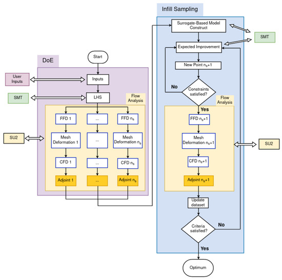
Figure 2.
Flowchart of the HEGOPLS optimization framework.
2.6. Single and Multi-Point Optimization
Many aerodynamic shape optimization studies in the literature typically consider a single flight condition, which, although not always explicitly named, can generally be categorized as single-point optimization. In contrast, optimization cases that incorporate multiple flight conditions are referred to as multi-point optimization. Studies involving multiple flight envelopes are relatively rare due to the significant increase in computational cost and the heightened complexity of the problem [14,20,21].
In this study, the RAE 2822 drag optimization case is investigated under both single-point and multi-point optimization settings. As mentioned, multi-point optimization involves multiple flight conditions. The outcomes of both single- and multi-point optimizations are analyzed and compared with each other, as well as with results available in the literature, in the Results section.
3. Case Definitions and CFD Validation
3.1. ADODG Test Case 2 Definition
To test the proposed optimization framework, Test Case 2 from the Aerodynamic Design Optimization Discussion Group (ADODG) benchmark cases has been selected for this study [1]. This two-dimensional case is widely adopted by researchers and research groups working in aerodynamic shape optimization and represents a transonic, viscous, single-point optimization problem. The baseline shape for this case is the RAE 2822 airfoil, and the optimization objective is defined as minimizing drag while satisfying constraints on the lift coefficient, moment coefficient, and surface area.
The flight conditions and the optimization problem definition for the single-point optimization setup are summarized in Equations (10)–(15). Additionally, a literature review table, which includes whether each study addresses the ADODG Test Case 2 and the corresponding cell size, is presented in the Results section along with the optimization results. Furthermore, for the multi-point optimization conducted in this study, the selected flight conditions and the problem definition are summarized in Equations (16)–(18). For the multi-point optimization case, no definition has been provided by the ADODG group; however, such a definition is available in the work of Koratikere and Leifsson [20]. The literature review table is updated accordingly by incorporating the flight conditions, and the comparisons are discussed in the Results section.
ADODG Test Case 2 (RAE 2822 airfoil single-point optimization) flow conditions and optimization definition can be expressed as follows:
where is Mach number, is Reynolds number, is drag coefficient, is lift coefficient, is moment coefficient, A is the surface area.
The conditions and corresponding weights (w) of the multi-point optimization are listed in Equations (16)–(18) and Table 4, respectively.
Table 4.
Flight conditions and corresponding weights (w) for the multi-point optimization.
3.2. Design Variables and DoE
The optimization components of the framework were implemented using the SMT code. For the Design of Experiment (DoE) phase, 20 samples were selected, while 80 design iterations were used for Infill Sampling. The correlation function was chosen as the Squared Exponential (Gaussian), with initial hyperparameter set as 0.01 with lower and upper bounds for defined as and 20, respectively. The design space is specified with lower and upper bounds of −0.01 and 0.01, respectively.
3.3. Three Mesh Levels and Comparison
In this section, the goal is to investigate the flow physics around the RAE 2822 airfoil under the specified flight conditions using three different mesh levels and to determine the appropriate mesh level for the subsequent optimization studies. The different mesh levels were generated using the Gmsh open-source software [45]. All meshes are O-type grids, featuring a boundary layer mesh near the airfoil to accurately capture the flow behavior close to the surface, followed by an unstructured mesh in the farfield region.
Table 5 summarizes the key characteristics of each mesh level, including the number of elements, the elapsed time for the CFD simulation in seconds (s), the obtained value in drag counts (, i.e., 1 drag count is equal to a of ), and the corresponding value, which represents a dimensionless wall distance used to assess the resolution quality of the near-wall mesh.
Table 5.
Mesh levels and corresponding CFD performance indicators.
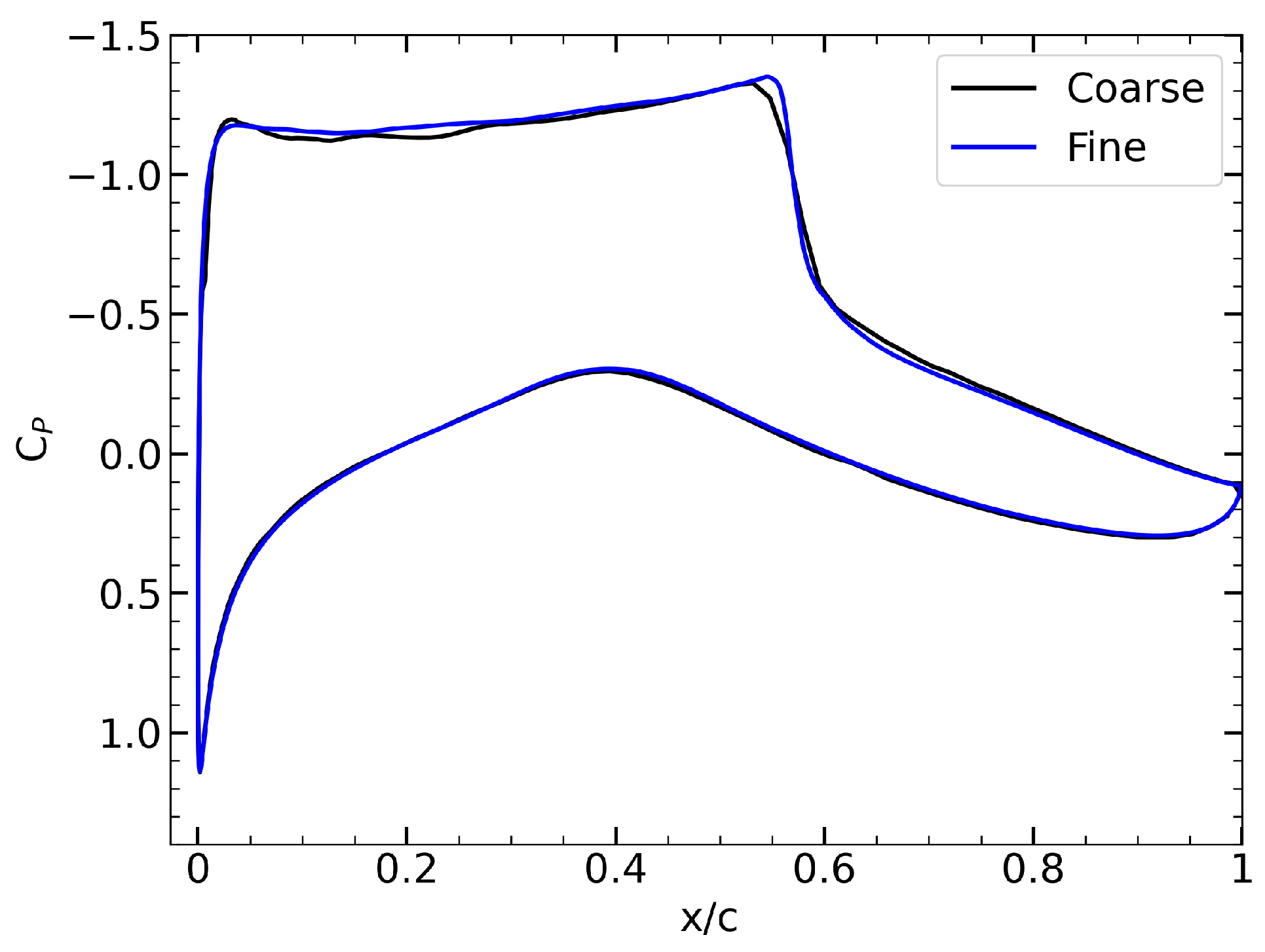
By evaluating the overall values, it is observed that the differences among the three mesh levels are negligible when considering the associated computational costs. The pressure coefficient distributions around the airfoil for the coarse, medium, and fine mesh levels are examined, the coarse and medium mesh levels resemble each other. The coarse and fine mesh levels are plotted in Figure 3, demonstrating very close agreement between the two.
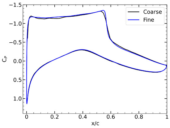
Figure 3.
Pressure coefficient distributions of the coarse (black line) and fine (blue line) mesh levels.
Given the good agreement with the fine mesh and the significant computational cost savings, the coarse mesh level is selected as the baseline mesh for the optimization studies conducted in this work.
For a more detailed visualization of the selected mesh, the mesh structure around the airfoil, including both the farfield region and the vicinity of the airfoil, is illustrated in Figure 4.
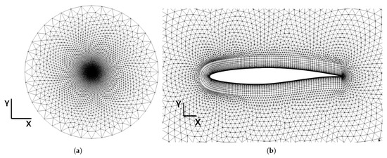
Figure 4.
The mesh structure around the airfoil: (a) The farfield region. (b) The vicinity of the airfoil.
3.4. CFD Validation with Experiment
In the study conducted by Cook et al. [46], experimental tests were performed around the RAE 2822 airfoil under the flight conditions listed in Table 6 to investigate the flow physics.
Table 6.
Flow conditions for experiment.
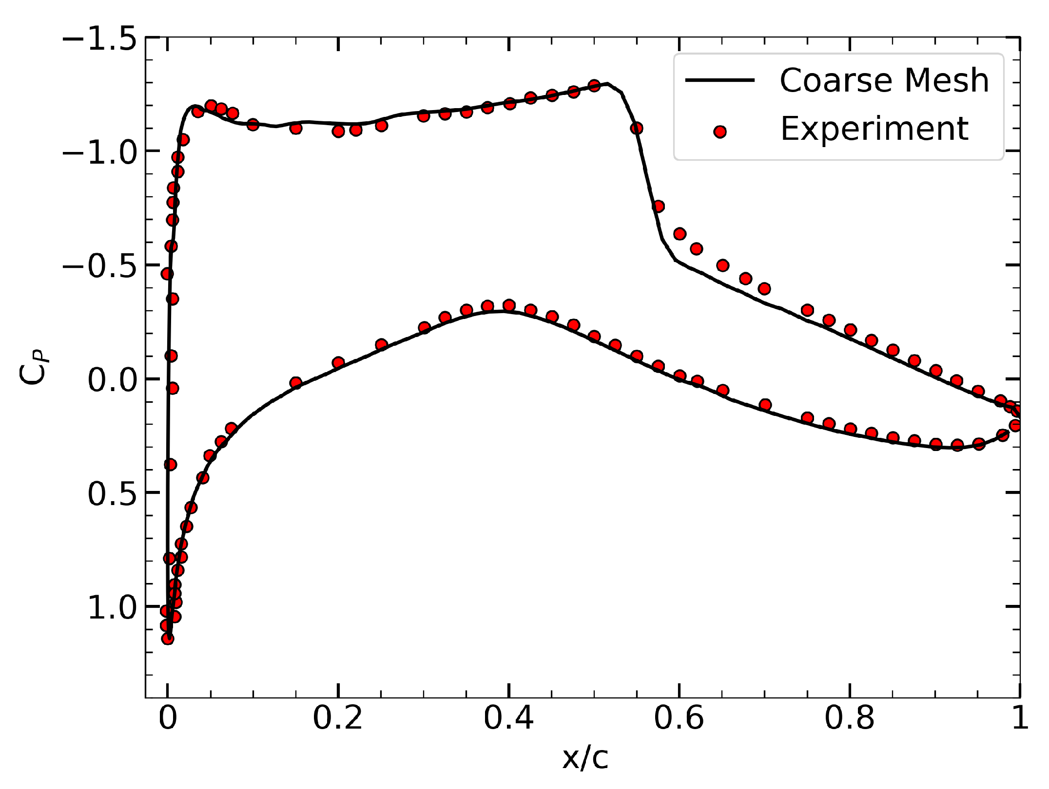
CFD simulations were carried out here using the coarse mesh under the same experimental conditions, and the results were compared with the experimental data provided by Cook et al. [46] to validate the accuracy of the mesh.
The comparison is visualized in Figure 5. Upon examining Figure 5, it can be observed that the CFD results obtained with the coarse mesh are in very good agreement with the experimental data, thus confirming that the selected coarse mesh is an appropriate choice for the optimization studies.
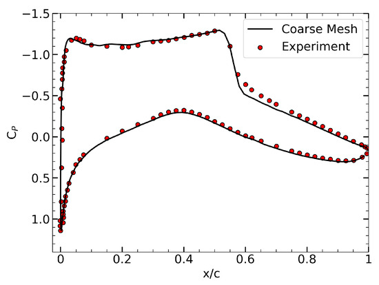
Figure 5.
Comparison of the pressure coefficient distribution between the coarse mesh and experimental data for the RAE 2822 airfoil.
3.5. Constraint in SU2
This section briefly explains how the lift coefficient () constraint, mentioned in the optimization problem definition, is handled in this work. One of the advantages of using the SU2 code is the constraint mechanism, which is implemented as follows. To achieve the target lift coefficient before the solution, the angle of attack of the object under investigation is adjusted during the CFD simulation by varying it within a predefined range. This process is summarized in Equation (19).
where is the current angle of attack, is the target lift coefficient, is the current lift coefficient, and is the fixed angle increment, which has been set to 0.2.
4. Results
4.1. Single-Point Optimization Results and Evaluation
The flight conditions and optimization problem definition for the single-point optimization of the RAE 2822 airfoil were provided in Equations (10)–(15). In this section, the results obtained from the single-point optimization studies based on this definition are evaluated. The current study was conducted using 14 design variables, the distribution of which is illustrated in Figure 1.
As shown in Table 7, the results obtained from the single-point optimization are presented. In this table, the drag coefficients in drag counts, the percentage improvements compared to the baseline RAE 2822 airfoil, the corresponding angles of attack, lift coefficients, and elapsed times in minutes are provided for the optimum airfoils obtained using the surrogate-based optimization methods and the adjoint-based method discussed within the scope of this study. Based on the table, it is observed that the highest improvement was achieved using the GEK method with 50.47%. This can be explained by the enrichment of the GEK method’s dataset with gradient information alongside y values, leading to superior performance compared to the other methods. The second-best performance was achieved using the GEKPLS method with an improvement of 49.41%. A similar explanation regarding the use of gradient information can be made for the GEKPLS method as well. The KRG method yielded an improvement of 43.74%, while the adjoint-based method achieved a 35.79% improvement, indicating that, for this particular case, surrogate-based methods outperformed the gradient-based approach.
Table 7.
Single-point optimization results comparison of drag coefficients (in drag counts) obtained using different optimization methods for RAE 2822 airfoil.
While Table 7 provides an overview of the drag coefficient values and improvements, a more detailed examination of the optimization results and the underlying physics can be performed by referring to Figure 6. The figure on the left shows the shapes of the optimum airfoils, whereas the figure on the right visualizes the distributions over the optimum airfoils obtained using each method. Upon inspecting the distributions, it is evident that each optimization method significantly improved the pressure distributions compared to the baseline geometry, particularly by weakening the shock wave near . It can also be interpreted that the GEK method was more effective in spreading the abrupt drop over the airfoil surface compared to the other methods.
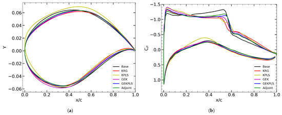
Figure 6.
Comparison of (a) the airfoil shapes and (b) pressure coefficients obtained from single-point optimization results using different optimization methods, both with the baseline and among each other.
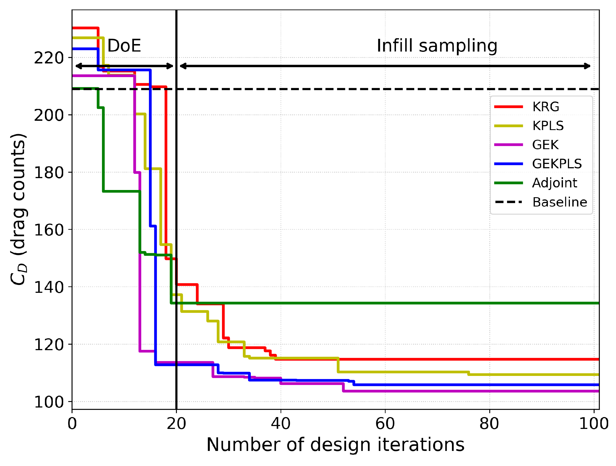
Figure 7 presents the design iteration versus evolution for each optimization method. This plot illustrates how the objective function, , evolved throughout the design optimization process. The graph is plotted by drawing the best minimum value obtained so far at each iteration, often referred to as a “staircase plot” in some studies. It is observed that for the surrogate-based methods, the first 20 iterations correspond to the Design of Experiments (DoE) phase, while the remaining 80 iterations are used for infill sampling. As expected, improvements continue after the DoE phase for surrogate-based methods. In contrast, for the gradient-based adjoint method, a rapid initial improvement is seen; however, it eventually gets stuck at a local minimum.
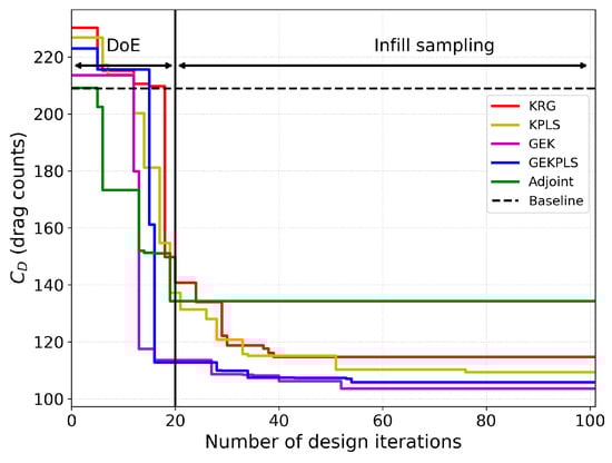
Figure 7.
Drag coefficient history during optimization process for different optimization methods for single-point optimization.
Table 8 and Table 9 share the results from the present study along with those from the literature that also focused on RAE 2822 airfoil optimization through single-point optimization. Some of the cases adopted the ADODG Test Case 2 conditions, which were previously specified in Table 1 and Table 2. In these tables, each study’s baseline drag coefficient, optimum drag coefficient in drag counts, the corresponding improvement percentage, and the number of design variables (DV) used are reported.
Table 8.
Single-point gradient-based optimization comparison of drag coefficients (in drag counts) with results reported in the literature for RAE 2822 airfoil.
Table 9.
Single-point gradient-free optimization comparison of drag coefficients (in drag counts) with results reported in the literature for RAE 2822 airfoil.
As stated in the Introduction section in Table 1 and Table 2, the results are classified into two groups: gradient-based and gradient-free methods. A similar classification is made here for evaluation. The adjoint results from the present study and the best surrogate-based result obtained using the GEK method are compared against the literature. When examining the gradient-based results first, it is observed that most studies used more than 16 design variables, achieving improvements of over 30%. On the other hand, when reviewing the gradient-free methods, it is noted that the number of design variables used is generally lower than in gradient-based studies, except for the study by Özkaya and Gauger [18], which utilized 38 design variables but only achieved an 18.14% improvement, which is relatively low compared to others. Other studies employing gradient-free approaches generally achieved improvements over 40% with fewer design variables. It can be concluded that the GEK method in the present study, achieving a 50.47% improvement, demonstrated strong performance compared to the literature.
To sum up, the single-point optimization results reveal that surrogate-based optimization methods, particularly those enriched with gradient information such as GEK and GEKPLS, outperform the classical gradient-based adjoint method in terms of drag reduction for the RAE 2822 airfoil under the ADODG Test Case 2 conditions. The GEK method achieved the highest improvement with a 50.47% reduction in drag counts, followed closely by GEKPLS with 49.41%, whereas the adjoint method yielded a 35.79% improvement. The analysis of distributions and design iteration histories further substantiates these findings, showing a more effective shock control and smoother optimization convergence for surrogate-based methods. Additionally, the comparative review with literature results demonstrates that the performance achieved in this study is highly competitive, even when compared with studies employing a greater number of design variables. These outcomes underline the capability and efficiency of the proposed HEGOPLS framework for aerodynamic shape optimization tasks.
4.2. Multi-Point Optimization Results
In this section, the results obtained from the multi-point optimization studies are analyzed using 14 design variables, and comparisons with similar studies in the literature are discussed. First, the outcomes obtained by applying the proposed methods to the problem defined in Equations (16)–(18) are summarized in Table 10. This table presents the total , the individual and values for each flight condition (point), as well as the corresponding values and the total elapsed time in minutes for each method.
Table 10.
Multi-point optimization results comparison obtained by different optimization methods for RAE 2822 airfoil.
Upon examining Table 10, it is observed that the GEKPLS and GEK methods demonstrate strong performances with overall drag reduction improvements of 43.92% and 41.58%, respectively. Similar to the single-point results, the presence of gradient information enhances the performance of these two methods. It is also seen that the KPLS method achieves a 42.80% improvement, ranking just behind GEKPLS, while the KRG method provides a comparable performance with a 41.27% improvement. Meanwhile, the adjoint-based optimization results in a 34.84% drag reduction, indicating that it lags behind the surrogate-based methods in this case.
A point-by-point analysis reveals that for all methods, the highest drag coefficient is observed at Point 3, whereas lower drag coefficients are achieved for the other points. This is mainly attributed to the higher Mach number at Point 3. Although the conditions at Point 2 are similar to those in the single-point case, the performance is slightly lower in the multi-point setup, reflecting the increased complexity due to the larger number of conditions to be satisfied. As for the elapsed times, it is noted that the KRG and KPLS methods complete the optimization faster than the gradient-enhanced methods, as they are constructed without using gradient information.
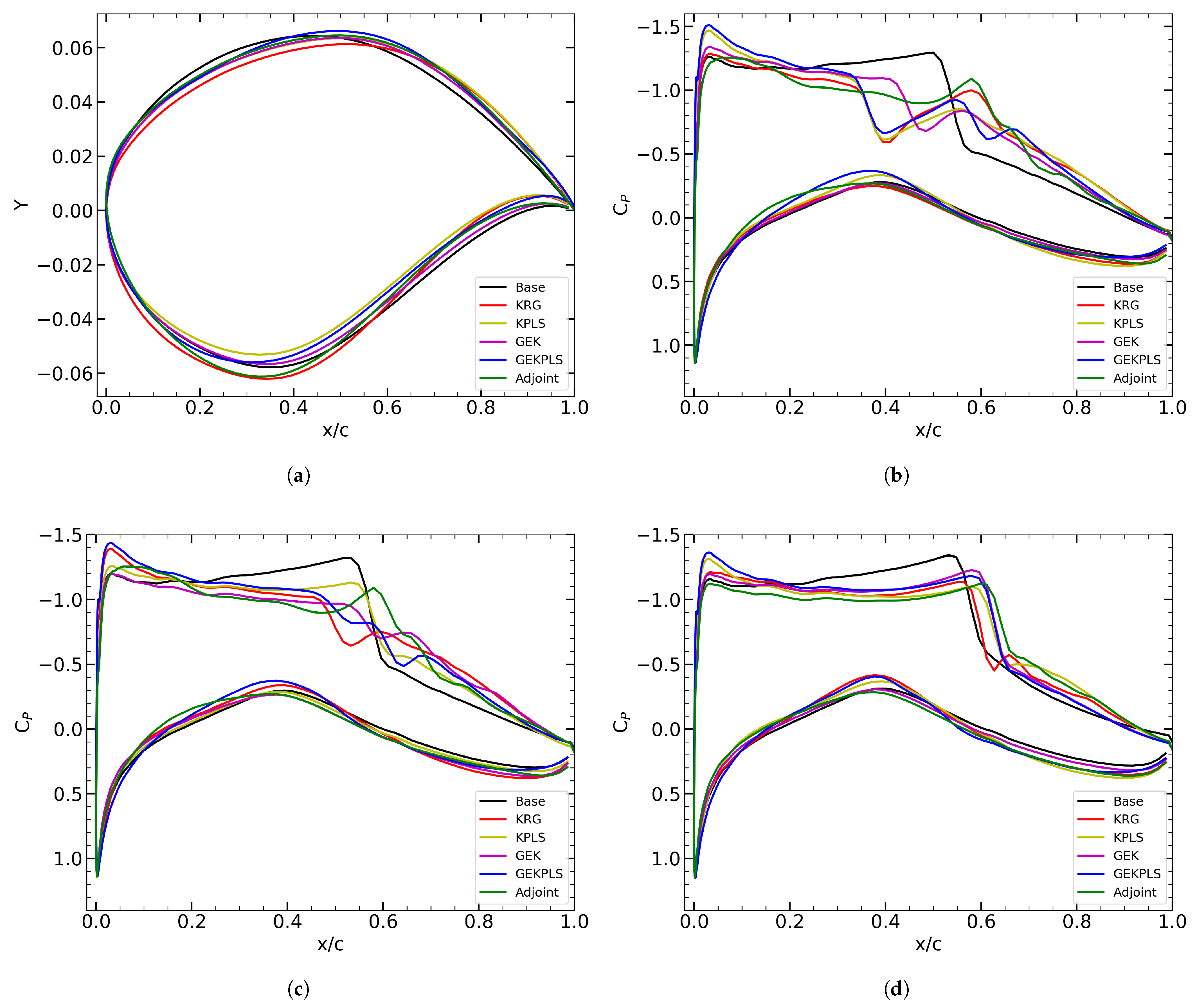
Figure 8 illustrates the optimum shapes obtained after multi-point optimization compared to the baseline shape, as well as the distributions over the airfoils for each point. From the distributions, a noticeable decrease in the shock wave strength is evident, which aligns with the improvements reflected in the overall results.
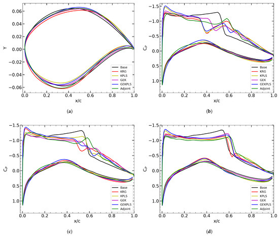
Figure 8.
Comparison of (a) the optimized airfoil shapes obtained using different optimization methods and the baseline geometry; Pressure coefficient distributions for (b) Point 1, (c) Point 2, and (d) Point 3, comparing the optimized airfoils with the baseline.
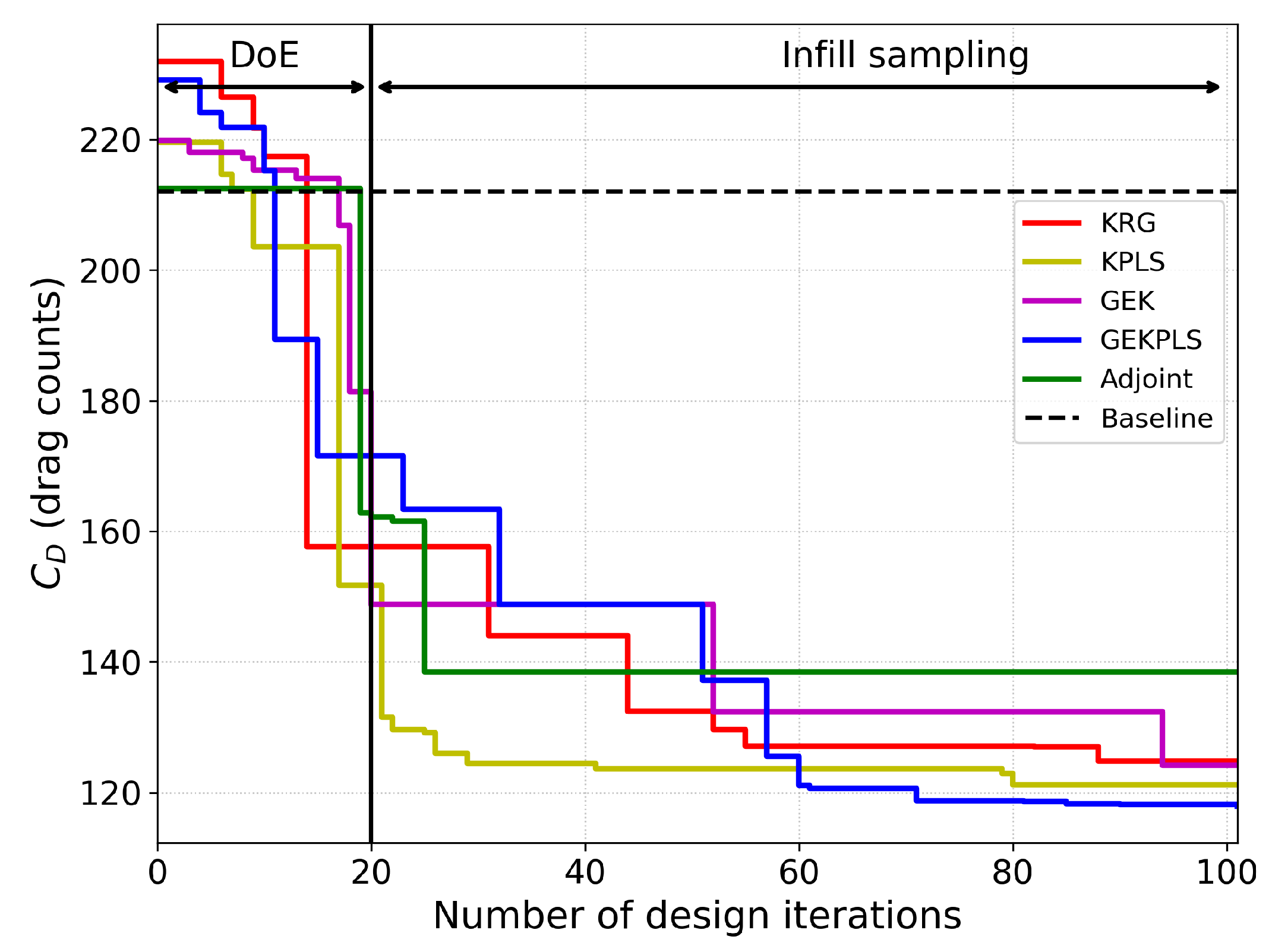
Figure 9 shows the evolution of over design iterations for each optimization method. It is observed that after the Design of Experiments (DoE) phase, the surrogate-based methods continue to achieve drag reductions as the process proceeds, whereas the gradient-based adjoint method experiences a rapid initial improvement followed by limited further gains.
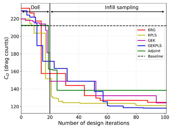
Figure 9.
Drag coefficient history during optimization process for different optimization methods for multi-point optimization.
Finally, Table 11 compares the present study results obtained by the GEKPLS method with three different references from the literature. As mentioned in Table 3 in the Introduction, Nagawkar et al. [14] focused on an Euler flow problem, while the other references dealt with transonic and viscous flow cases. The number of design variables (DVs) used across these studies are similar. In the table, it is noted that the present study, Koratikere and Leifsson [20], and Nagawkar et al. [14] use the same Mach numbers and weights, whereas Toal and Keane [21] prioritize a higher weight for . Regarding improvements, Nagawkar et al. [14] report a very high drag reduction of 80.33%, which can be attributed to the inviscid nature of their Euler-based case. In contrast, the present study, achieving 43.92% improvement with GEKPLS, demonstrates highly competitive performance compared to the other viscous flow cases in the literature.
Table 11.
Multi-point optimization comparison with results reported in the literature for RAE 2822 airfoil.
Multi-point optimization studies were conducted by considering the problem defined in Equations (16)–(18). Among the investigated methods, the GEKPLS method achieved the highest overall drag reduction with an improvement of 43.92%, closely followed by KPLS (42.80%) and GEK (41.58%). The KRG method also showed a comparable performance with a 41.27% improvement. In contrast, the adjoint-based approach achieved a 34.84% drag reduction, indicating the superior performance of the surrogate-based methods for this case.
distribution analyses revealed that the optimized designs successfully weakened the shock strength compared to the baseline, especially at higher Mach numbers. Design iteration plots indicated steady improvements beyond the DoE phase for surrogate-based methods, whereas the adjoint method showed rapid initial convergence followed by stagnation.
Compared with the literature, the present study using GEKPLS demonstrated strong competitiveness, achieving a 43.92% drag reduction for viscous flow conditions, outperforming most similar works under comparable optimization setups.
5. Discussion
The present study assessed the performance of surrogate-based and gradient-based optimization methods for aerodynamic shape optimization using the RAE 2822 airfoil as a benchmark case. Validation against experimental data confirmed the CFD setup’s ability to capture critical flow features, providing a solid foundation for subsequent optimization. In single-point optimization, surrogate-based methods incorporating gradient information (GEK and GEKPLS) significantly outperformed KRG and KPLS approaches and the adjoint-based method, consistent with prior findings that highlight the advantages of gradient-enriched models. Similarly, in multi-point optimization, the GEKPLS method demonstrated strong performance under transonic, viscous flow conditions, achieving results comparable to or exceeding those reported in the literature.
These results reinforce the hypothesis that incorporating gradient information into surrogate models improves both optimization efficiency and final design quality. The performance gap observed between surrogate-based and gradient-based methods also suggests that, for problems involving complex flow phenomena and multiple operating conditions, surrogate models can provide not only competitive but also more robust solutions with controlled computational resources.
Comparison with literature studies further validated the competitiveness of the present methods, particularly under viscous flow conditions. These results highlight the advantages of incorporating gradient information into surrogate modeling and confirm the robustness of the proposed strategies for both single and multi-point aerodynamic optimizations.
In a broader context, the findings suggest that hybrid frameworks leveraging both surrogate modeling and gradient information can be critical for future high-fidelity aerodynamic optimizations. Future research may explore extensions to three-dimensional configurations, unsteady flows, and the integration of physics-informed machine learning approaches to further enhance surrogate model capabilities and optimization robustness across a wider range of aerodynamic design problems.
6. Conclusions
This study has presented a comprehensive evaluation of surrogate-based and gradient-based aerodynamic shape optimization approaches applied to the RAE 2822 airfoil under both single-point and multi-point conditions. Validation against experimental data confirmed the accuracy of the CFD setup, providing confidence in the optimization results. Surrogate-based methods, particularly those enriched with gradient information (GEK and GEKPLS), consistently outperformed traditional KRG, KPLS and adjoint-based methods in terms of drag reduction and computational efficiency. These findings highlight the value of combining surrogate modeling with gradient information to achieve robust and efficient optimizations, especially in complex aerodynamic design spaces. Work to extend these methodologies to three-dimensional and unsteady flow problems to further test their scalability and effectiveness is underway.
Author Contributions
Conceptualization, N.Ş., H.U.A., and Ş.Y.; methodology, N.Ş.; software, N.Ş.; validation, N.Ş.; formal analysis, N.Ş.; investigation, N.Ş.; resources, N.Ş.; data curation, N.Ş.; writing—original draft preparation, N.Ş.; writing—review and editing, N.Ş., H.U.A. and Ş.Y.; visualization, N.Ş.; supervision, H.U.A. and Ş.Y. All authors have read and agreed to the published version of the manuscript.
Funding
This research received no external funding.
Data Availability Statement
The original contributions presented in this study are included in the article. Further inquiries can be directed to the corresponding author.
Acknowledgments
The authors would like to acknowledge the Turkish Aerospace company for providing the computational resources that supported this research. Their contribution was instrumental in enabling the numerical simulations and optimization studies presented in this work.
Conflicts of Interest
Authors Niyazi Şenol and Şahin Yiğit were employed by the Turkish Aerospace Company. The remaining authors declare that the research was conducted in the absence of any commercial or financial relationships that could be construed as a potential conflict of interest.
Abbreviations
The following abbreviations are used in this manuscript:
| EGO | Efficient global optimization |
| RAE | Royal Aircraft Establishment |
| CFD | Computational fluid dynamics |
| KRG | Kriging |
| KPLS | Kriging with partial least squares |
| GEK | Gradient-enhanced Kriging |
| GEKPLS | Gradient-enhanced Kriging with partial least squares |
| ADODG | AIAA Aerodynamic Design Optimization Discussion Group |
| SU2 | Stanford University Unstructured |
| FSQP | Feasible sequential quadratic programming |
| RSM | Response surface models |
| MLO | Multi-level optimization |
| EI | Expected improvement |
| MFEI | Multi-fidelity expected improvement |
| MHK | Multi-level hierarchical Kriging |
| NN | Neural network |
| MM | Manifold mapping |
| GPR | Gaussian process regression |
| AKC | Automatic kernel construction |
| cEGO | Constrained efficient global optimization |
| FFD | Free-form deformation |
| AD | Automatic differentiation |
| DoE | Design of experiments |
| LHS | Latin hypercube sampling |
| HEGOPLS | Hybrid efficient global optimization with partial least squares |
| SMT | Surrogate Modeling Toolbox |
| DV | Design variable |
References
- Aerodynamic Design Optimization Discussion Group (ADODG). AIAA Aerodynamic Design Optimization Discussion Group Benchmark Problems; McGill University Computational Aerodynamics Group: Montreal, QC, Canada, 2022; Available online: https://sites.google.com/view/mcgill-computational-aerogroup/adodg (accessed on 18 April 2025).
- Poole, D.J.; Allen, C.B.; Rendall, T. Control point-based aerodynamic shape optimization applied to AIAA ADODG test cases. In Proceedings of the 53rd AIAA Aerospace Sciences Meeting, Kissimmee, FL, USA, 5–9 January 2015; p. 1947. [Google Scholar]
- Yang, G.; Da Ronch, A. Aerodynamic Shape Optimisation of Benchmark Problems Using SU2. In Proceedings of the 2018 AIAA/ASCE/AHS/ASC Structures, Structural Dynamics, and Materials Conference, Kissimmee, FL, USA, 8–12 January 2018; p. 0412. [Google Scholar]
- Abergo, L. Aerodynamic Optimization Based on a Discrete Adjoint Framework and Radial Basis Function Mesh Deformation in SU2. Master’s Thesis, Politecnico di Milano, Milano, Italy, 2021. [Google Scholar]
- Carrier, G.; Destarac, D.; Dumont, A.; Meheut, M.; Salah El Din, I.; Peter, J.; Pestana, M. Gradient-Based Aerodynamic Optimization with the elsA Software. In Proceedings of the 52nd Aerospace Sciences Meeting, National Harbor, MD, USA, 13–17 January 2014; p. 568. [Google Scholar]
- He, X.; Li, J.; Mader, C.A.; Yildirim, A.; Martins, J.R. Robust Aerodynamic Shape Optimization—From a Circle to an Airfoil. Aerosp. Sci. Technol. 2019, 87, 48–61. [Google Scholar] [CrossRef]
- Lee, C.; Koo, D.; Telidetzki, K.; Buckley, H.; Gagnon, H.; Zingg, D.W. Aerodynamic Shape Optimization of Benchmark Problems Using Jetstream. In Proceedings of the 53rd AIAA Aerospace Sciences Meeting, Kissimmee, FL, USA, 5–9 January 2015; p. 0262. [Google Scholar]
- Ren, J.; Thelen, A.S.; Amrit, A.; Du, X.; Leifsson, L.T.; Tesfahunegn, Y.; Koziel, S. Application of Multifidelity Optimization Techniques to Benchmark Aerodynamic Design Problems. In Proceedings of the 54th AIAA Aerospace Sciences Meeting, San Diego, CA, USA, 4–8 January 2016; p. 1542. [Google Scholar]
- Marques, S.; Hewitt, P. Aerofoil Optimisation Using CST Parameterisation in SU2. In Proceedings of the Royal Aeronautical Society Applied Aerodynamics Group Conference, Bristol, UK, 23–25 June 2014. [Google Scholar]
- Zhang, Y.; Han, Z.H.; Shi, L.; Song, W.P. Multi-Round Surrogate-Based Optimization for Benchmark Aerodynamic Design Problems. In Proceedings of the 54th AIAA Aerospace Sciences Meeting, San Diego, CA, USA, 4–8 January 2016; p. 1545. [Google Scholar]
- Nagawkar, J.R.; Leifsson, L.T.; He, P. Aerodynamic Shape Optimization Using Gradient-Enhanced Multifidelity Neural Networks. In Proceedings of the AIAA SciTech 2022 Forum, San Diego, CA, USA, 3–7 January 2022; p. 2350. [Google Scholar]
- Wang, Y.; Han, Z.H.; Zhang, Y.; Song, W.P. Efficient Global Optimization Using Multiple Infill Sampling Criteria and Surrogate Models. In Proceedings of the 2018 AIAA Aerospace Sciences Meeting, Kissimmee, FL, USA, 8–12 January 2018; p. 0555. [Google Scholar]
- Zhang, Y.; Han, Z.H.; Song, W.P. Multi-Fidelity Expected Improvement Based on Multi-Level Hierarchical Kriging Model for Efficient Aerodynamic Design Optimization. Eng. Optim. 2024, 56, 2408–2430. [Google Scholar] [CrossRef]
- Nagawkar, J.; Ren, J.; Du, X.; Leifsson, L.; Koziel, S. Single- and Multipoint Aerodynamic Shape Optimization Using Multifidelity Models and Manifold Mapping. J. Aircraft 2021, 58, 591–608. [Google Scholar] [CrossRef]
- Xue, Y.; Yang, Y.; Yao, S.; Zhao, W.; Chen, L. Optimizing Aerodynamic Shape of Benchmark Problems Using an Improved Gaussian Process Regression Algorithm. Eng. Appl. Comput. Fluid Mech. 2025, 19, 2456500. [Google Scholar] [CrossRef]
- Han, Z.H.; Zhang, K.S. Surrogate-Based Optimization. In Real-World Applications of Genetic Algorithms; Springer: Berlin, Germany, 2012; pp. 343–362. [Google Scholar]
- Tesfahunegn, Y.A.; Koziel, S.; Gramanzini, J.R.; Hosder, S.; Han, Z.H.; Leifsson, L. Application of Direct and Surrogate-Based Optimization to Two-Dimensional Benchmark Aerodynamic Problems: A Comparative Study. In Proceedings of the 53rd AIAA Aerospace Sciences Meeting, Kissimmee, FL, USA, 5–9 January 2015; pp. 5–9. [Google Scholar]
- Özkaya, E.; Gauger, N.R. Global Aerodynamic Design Optimization via Primal-Dual Aggregation Method. In New Results in Numerical and Experimental Fluid Mechanics XII: Contributions to the 21st STAB/DGLR Symposium, Darmstadt, Germany, 2018; Springer International Publishing: Berlin/Heidelberg, Germany, 2020; pp. 48–57. [Google Scholar]
- Koratikere, P. Efficient Sequential Sampling for Neural Network-Based Surrogate Modeling. Master’s Thesis, Purdue University, West Lafayette, IN, USA, 2023. [Google Scholar]
- Koratikere, P.; Leifsson, L.T. Multi-Point Airfoil Shape Optimization Using Neural Network-Based Sequential Sampling. In Proceedings of the AIAA SCITECH 2024 Forum, Orlando, FL, USA, 8–12 January 2024; p. 2234. [Google Scholar]
- Toal, D.J.; Keane, A.J. Efficient Multipoint Aerodynamic Design Optimization via Cokriging. J. Aircr. 2011, 48, 1685–1695. [Google Scholar] [CrossRef]
- Jones, D.R.; Schonlau, M.; Welch, W.J. Efficient Global Optimization of Expensive Black-Box Functions. J. Glob. Optim. 1998, 13, 455–492. [Google Scholar] [CrossRef]
- Zhang, Y.; Han, Z.H.; Zhang, K.S. Variable-Fidelity Expected Improvement Method for Efficient Global Optimization of Expensive Functions. Struct. Multidiscip. Optim. 2018, 58, 1431–1451. [Google Scholar] [CrossRef]
- Wang, K.; Han, Z.; Zhang, K.; Song, W. Efficient Global Aerodynamic Shape Optimization of a Full Aircraft Configuration Considering Trimming. Aerospace 2023, 10, 734. [Google Scholar] [CrossRef]
- Krige, D.G. A Statistical Approach to Some Basic Mine Valuation Problems on the Witwatersrand. J. S. Afr. Inst. Min. Metall. 1951, 52, 119–139. [Google Scholar]
- Jeong, S.; Obayashi, S.; Yamamoto, K. Aerodynamic Optimization Design with Kriging Model. Trans. Jpn. Soc. Aeronaut. Space Sci. 2005, 48, 161–168. [Google Scholar] [CrossRef]
- Laurenceau, J.; Meaux, M.; Montagnac, M.; Sagaut, P. Comparison of Gradient-Based and Gradient-Enhanced Response-Surface-Based Optimizers. AIAA J. 2010, 48, 981–994. [Google Scholar] [CrossRef]
- Zhang, Y.; Han, Z.H.; Leifsson, L.T. Surrogate-Based Optimization Applied to Benchmark Aerodynamic Design Problems. In Proceedings of the 35th AIAA Applied Aerodynamics Conference, Denver, CO, USA, 5–9 June 2017; p. 4367. [Google Scholar]
- Zhang, W.; Gao, Z.; Wang, C.; Xia, L. Kriging-Based Space Exploration Global Optimization Method in Aerodynamic Design. Int. J. Aerosp. Eng. 2023, 2023, 4493349. [Google Scholar] [CrossRef]
- Bouhlel, M.A.; Bartoli, N.; Otsmane, A.; Morlier, J. Improving Kriging Surrogates of High-Dimensional Design Models by Partial Least Squares Dimension Reduction. Struct. Multidiscip. Optim. 2016, 53, 935–952. [Google Scholar] [CrossRef]
- Özkaya, E.; Rottmayer, J.; Gauger, N.R. Gradient Enhanced Surrogate Modeling Framework for Aerodynamic Design Optimization. In Proceedings of the AIAA SCITECH 2024 Forum, Orlando, FL, USA, 8–12 January 2024; p. 2670. [Google Scholar]
- Song, C.; Han, Z.; Zhang, Y. A New Formulation of Gradient-Enhanced Surrogate Model and Application to Aerodynamic Design. In Proceedings of the 34th AIAA Applied Aerodynamics Conference, Washington, DC, USA, 13–17 June 2016; p. 3869. [Google Scholar]
- Bouhlel, M.A.; Martins, J.R. Gradient-Enhanced Kriging for High-Dimensional Problems. Eng. Comput. 2019, 35, 157–173. [Google Scholar] [CrossRef]
- Chauhan, D.; Chandrashekarappa, P.; Duvigneau, R. Wing Shape Optimization Using FFD and Twist Parameterization. In Proceedings of the 12th Aerospace Society of India CFD Symposium, Bangalore, India, 10–11 August 2010. [Google Scholar]
- Masters, D.A.; Taylor, N.J.; Rendall, T.C.S.; Allen, C.B.; Poole, D.J. Geometric Comparison of Aerofoil Shape Parameterization Methods. AIAA J. 2017, 55, 1575–1589. [Google Scholar] [CrossRef]
- Sacks, J.; Welch, W.J.; Mitchell, T.J.; Wynn, H.P. Design and Analysis of Computer Experiments. Stat. Sci. 1989, 4, 409–423. [Google Scholar] [CrossRef]
- Han, Z.H.; Görtz, S.; Zimmermann, R. Improving Variable-fidelity Surrogate Modeling via Gradient-enhanced Kriging and a Generalized Hybrid Bridge Function. Aerosp. Sci. Technol. 2013, 25, 177–189. [Google Scholar] [CrossRef]
- Forrester, A.I.; Keane, A.J. Recent Advances in Surrogate-Based Optimization. Prog. Aerosp. Sci. 2009, 45, 50–79. [Google Scholar] [CrossRef]
- Chung, H.S.; Alonso, J. Using Gradients to Construct Cokriging Approximation Models for High-dimensional Design Optimization Problems. In Proceedings of the 40th AIAA Aerospace Sciences Meeting & Exhibit, Reno, NV, USA, 14–17 January 2002; p. 317. [Google Scholar]
- Cao, F.; Tang, Z.; Zhu, C.; Zhao, X. An Efficient Hybrid Multi-Objective Optimization Method Coupling Global Evolutionary and Local Gradient Searches for Solving Aerodynamic Optimization Problems. Mathematics 2023, 11, 3844. [Google Scholar] [CrossRef]
- Li, C.; Brezillon, J.; Görtz, S. A Framework for Surrogate-Based Aerodynamic Optimization. In Proceedings of the 29th AIAA Applied Aerodynamics Conference, Honolulu, HI, USA, 27–30 June 2011. [Google Scholar]
- Palacios, F.; Alonso, J.; Duraisamy, K.; Colonno, M.; Hicken, J.; Aranake, A.; Taylor, T. Stanford University Unstructured (SU2): An Open-Source Integrated Computational Environment for Multi-Physics Simulation and Design. In Proceedings of the 51st AIAA Aerospace Sciences Meeting Including the New Horizons Forum and Aerospace Exposition, Grapevine, TX, USA, 7–10 January 2013; p. 287. [Google Scholar]
- Bouhlel, M.A.; Hwang, J.T.; Bartoli, N.; Lafage, R.; Morlier, J.; Martins, J.R. A Python Surrogate Modeling Framework with Derivatives. Adv. Eng. Softw. 2019, 135, 102662. [Google Scholar] [CrossRef]
- SMT Developers. SMT: Surrogate Modeling Toolbox; GitHub Repository. 2024. Available online: https://github.com/SMTorg/smt (accessed on 18 April 2025).
- Gmsh: 3D Finite Element Mesh Generator. Available online: https://gmsh.info/ (accessed on 18 April 2025).
- Cook, P.H.; McDonald, M.A.; Firmin, M.C.P. Aerofoil RAE 2822—Pressure Distributions, and Boundary Layer and Wake Measurements. In Experimental Data Base for Computer Program Assessment, No. 138, AGARD Advisory Report; AGARD: Neuilly-sur-Seine, France, 1979; pp. A6-1–A6-77. [Google Scholar]


Disclaimer/Publisher’s Note: The statements, opinions and data contained in all publications are solely those of the individual author(s) and contributor(s) and not of MDPI and/or the editor(s). MDPI and/or the editor(s) disclaim responsibility for any injury to people or property resulting from any ideas, methods, instructions or products referred to in the content. |
© 2025 by the authors. Licensee MDPI, Basel, Switzerland. This article is an open access article distributed under the terms and conditions of the Creative Commons Attribution (CC BY) license (https://creativecommons.org/licenses/by/4.0/).