
Printability Optimization of LDPE-Based Composites for Tool Production in Crewed Space Missions: From Numerical Simulation to Additive Manufacturing


Abstract
1. Introduction
2. Materials and Methods
2.1. Numerical Simulation
2.1.1. Simulation Workflow
- , , = normal stresses acting along the x, y, and z axes, respectively;
- , , = shear stresses acting on the faces of the material element.
2.1.2. Description of Analyzed Geometries
2.1.3. Development of a Custom Material Model
2.1.4. Investigation of Printing Parameter Variation in FFF Technique
2.2. Three-Dimensional Printing of LDPE/PAL Composites
3. Results
3.1. Numerical Simulation
3.2. Three-Dimensional Printing of Parts
4. Conclusions
Author Contributions
Funding
Data Availability Statement
Conflicts of Interest
Abbreviations
| AM | Additive manufacturing |
| CELSS | Controlled Ecological Life Support System |
| CTE | Coefficient of thermal expansion |
| DED | Directed Energy Deposition |
| DSC | Differential Scanning Calorimetry |
| DMA | Dynamic mechanical analysis |
| ESA | European Space Agency |
| FFF | Fused filament fabrication |
| ISRU | In situ resource utilization |
| ISS | International Space Station |
| LCA | Life Cycle Assessment |
| LDPE | Low-density polyethylene |
| LEO | Low Earth orbit |
| MBCS | Multi-Bag Compaction System |
| NASA | National Aeronautics and Space Administration |
| PAL | PET-aluminum-LDPE |
| PVA | Polyvinyl alcohol |
| SEM | Scanning electron microscopy |
| SC-DW | Solvent-Cast Direct-Write |
| STL | Standard Tessellation Language |
| TCPS | Trash Compaction and Processing System |
| TUI | Tethers Unlimited Inc. |
Appendix A

| Square Specimen—Simulation Results | |||||
|---|---|---|---|---|---|
| Run | Infill Pattern | Printing Speed [mm/s] | Bed Temperature [°C] | Residual Stress (von Mises) [MPa] | Total Warpage [mm] |
| 1. | Zig Zag | 50 | 60 | 1.204 | 1.741 |
| 2. | Triangles | 50 | 60 | 1.205 | 1.74 |
| 3. | Grid | 50 | 60 | 1.212 | 1.74 |
| 4. | Tri-Hexagon | 50 | 60 | 1.205 | 1.741 |
| 5. | Concentric | 50 | 60 | 1.198 | 1.74 |
| 6. | Concentric | 20 | 60 | 2.389 | 1.761 |
| 7. | Concentric | 30 | 60 | 1.802 | 1.751 |
| 8. | Concentric | 40 | 60 | 1.452 | 1.744 |
| 9. | Concentric | 50 | 70 | 1.198 | 1.74 |
| 10. | Concentric | 50 | 80 | 1.198 | 1.74 |
| 11. | Concentric | 50 | 90 | 1.198 | 1.74 |
| Wrench—Simulation Results | |||||
|---|---|---|---|---|---|
| Run | Infill Pattern | Printing Speed [mm/s] | Bed Temperature [°C] | Residual Stress (von Mises) [MPa] | Total Warpage [mm] |
| 1. | Zig Zag | 50 | 60 | 2.821 | 3.044 |
| 2. | Triangles | 50 | 60 | 2.898 | 3.106 |
| 3. | Grid | 50 | 60 | 2.851 | 3.107 |
| 4. | Tri-Hexagon | 50 | 60 | 2.984 | 3.106 |
| 5. | Concentric | 50 | 60 | 2.68 | 3.07 |
| 6. | Concentric | 20 | 60 | 5.34 | 3.12 |
| 7. | Concentric | 30 | 60 | 3.997 | 3.095 |
| 8. | Concentric | 40 | 60 | 3.205 | 3.08 |
| 9. | Concentric | 50 | 70 | 2.68 | 3.07 |
| 10. | Concentric | 50 | 80 | 2.68 | 3.07 |
| 11. | Concentric | 50 | 90 | 2.68 | 3.07 |
| Wheel—Simulation Results | |||||
|---|---|---|---|---|---|
| Run | Infill Pattern | Printing Speed [mm/s] | Bed Temperature [°C] | Residual Stress (von Mises) [MPa] | Total Warpage [mm] |
| 1. | Zig Zag | 50 | 60 | 3.172 | 1.624 |
| 2. | Triangles | 50 | 60 | 3.185 | 1.624 |
| 3. | Grid | 50 | 60 | 3.227 | 1.624 |
| 4. | Tri-Hexagon | 50 | 60 | 3.196 | 1.624 |
| 5. | Concentric | 50 | 60 | 3.137 | 1.624 |
| 6. | Concentric | 20 | 60 | 6.205 | 1.653 |
| 7. | Concentric | 30 | 60 | 4.663 | 1.639 |
| 8. | Concentric | 40 | 60 | 3.747 | 1.63 |
| 9. | Concentric | 50 | 70 | 3.137 | 1.624 |
| 10. | Concentric | 50 | 80 | 3.137 | 1.624 |
| 11. | Concentric | 50 | 90 | 3.137 | 1.624 |
References
- Russo, G.; Ciamarra, M.P.; Messidoro, P.; Voto, C.; Moronese, V.; Paudice, F.; Pederbelli, D.; Minichini, R.; D’Iorio, M.; Salvato, M. Cislunar City: The Outpost of Humankind Expansion into Space. In For Nature/With Nature: New Sustainable Design Scenarios; Springer Nature: Cham, Switzerland, 2024; pp. 999–1038. [Google Scholar]
- Sanders, G.B.; Kleinhenz, J.E.; Hilburger, M.W. Using ISRU and Surface Construction to Define Long-Term Lunar Infrastructure Needs. In Proceedings of the AIAA Aviation Forum and Ascend 2024, Las Vegas, NV, USA, 29 July–2 August 2024; p. 4840. [Google Scholar]
- Lachman, N.S. The Selene Mission: Paving the Way for a Large-Scale Commercial Moon Colony and a Multi-Trillion-Dollar Lunar Economy. Acceleron Aerosp. J. 2024, 2, 295–299. [Google Scholar] [CrossRef]
- Mukundan, A.; Patel, A.; Shastri, B.; Bhatt, H.; Phen, A.; Wang, H.C. The Dvaraka initiative: Mars’s first permanent human settlement capable of self-sustenance. Aerospace 2023, 10, 265. [Google Scholar] [CrossRef]
- Milakis, D. Beyond rockets: Transport planning for permanent space settlements. Transp. Rev. 2024, 44, 1–7. [Google Scholar] [CrossRef]
- Sawik, B. Space mission risk, sustainability and supply chain: Review, multi-objective optimization model and practical approach. Sustainability 2023, 15, 11002. [Google Scholar] [CrossRef]
- Boretti, A. Hydrogen economy key to a sustainable Martian colony. Int. J. Hydrogen Energy 2025, 109, 1314–1320. [Google Scholar] [CrossRef]
- Fogtman, A.; Baatout, S.; Baselet, B.; Berger, T.; Hellweg, C.E.; Jiggens, P.; La Tessa, C.; Narici, L.; Nieminen, P.; Sabatier, L.; et al. Towards sustainable human space exploration—Priorities for radiation research to quantify and mitigate radiation risks. NPJ Microgravity 2023, 9, 8. [Google Scholar] [CrossRef]
- Miraux, L.; Wilson, A.R.; Calabuig, G.J.D. Environmental sustainability of future proposed space activities. Acta Astronaut. 2022, 200, 329–346. [Google Scholar] [CrossRef]
- Sanders, G.B. (NASA Johnson Space Center, Houston, TX, USA) Space Resource Utilization: Near-Term Missions and Long-Term Plans for Human Exploration. In Proceedings of the Annual Joint PTMSS/SRR (Planetary & Terrestrial Mining Sciences Symposium/Space Resources Roundtable), Montréal, QC, Canada, 10–13 May 2015. No. JSC-CN-33116. [Google Scholar]
- Zhang, P.; Dai, W.; Niu, R.; Zhang, G.; Liu, G.; Liu, X.; Bo, Z.; Wang, Z.; Zheng, H.; Liu, C.; et al. Overview of the lunar in situ resource utilization techniques for future lunar missions. Space Sci. Technol. 2023, 3, 0037. [Google Scholar] [CrossRef]
- Veismann, M.; Tosi, L.P. Evaluation of low-pressure mechanical compression for Martian atmospheric CO2 capture: Implications for in-situ resource utilization. Acta Astronaut. 2025, 228, 769–791. [Google Scholar] [CrossRef]
- Ellery, A. Sustainable in-situ resource utilization on the moon. Planet. Space Sci. 2020, 184, 104870. [Google Scholar] [CrossRef]
- Mane, S. Sustainability, Sanitation and Recycling for Long Duration Space Missions. Int. J. Enhanc. Res. Sci. Technol. Eng. 2024, 13, 33–37. [Google Scholar]
- McKinley, M.K.; Ewert, M.K.; Borrego, M.A.; Fink, P.; Sepka, S.; Richardson, J.; Pitts, R.; Meier, A.; Hill, C. Logistics Reduction Advancements and Future Plans for NASA’s Exploration Missions. In Proceedings of the 53rd International Conference on Environmental Systems (ICES), Louisville, KY, USA, 21–25 July 2024. No. ICES-2024-073. [Google Scholar]
- Linne, D.L.; Palaszewski, B.A.; Gokoglu, S.A.; Balasubramaniam, B.; Hegde, U.G.; Gallo, C. Waste management options for long-duration space missions: When to reject, reuse, or recycle. In Proceedings of the 7th Symposium on Space Resource Utilization, National Harbor, MD, USA, 13–17 January 2014; p. 0497. [Google Scholar]
- Etlin, S.; Bielski, L.; Rose, J.; Morales, K.; Belman, A.; Alexander, E.; Li, E.; Lin, R.; Patel, K.; Rakhmonova, S.; et al. Enhanced astronaut hygiene and mission efficiency: A novel approach to in-suit waste management and water recovery in spacewalks. Front. Space Technol. 2024, 5, 1391200. [Google Scholar] [CrossRef]
- Klopotic, J.; Wyman, D.; Petrie, Z.; Wetzel, J. Design of a Trash Compaction & Processing System (TCPS) for Waste Management and Logistics Reduction in Long Duration Spaceflight. In Proceedings of the 2023 International Conference on Environmental Systems, Calgary, AB, Canada, 16–20 July 2023. [Google Scholar]
- Rini, E.; Ewert, M.; Chen, T. Integrated Waste Trade Study: Lunar Surface to Deep Space. In Proceedings of the 53rd International Conference on Environmental Systems (ICES), Louisville, KY, USA, 21–25 July 2024. [Google Scholar]
- Mohammad, K. Advancing Sustainability in Space: Innovations in Life Support Systems, Resource Utilization, and Waste Management for Long-Duration Space Missions. In Proceedings of the AIAA Aviation Forum and Ascend 2024, Las Vegas, NV, USA, 21–25 July 2025; p. 4868. [Google Scholar]
- Ai, W.; Deng, Y.; Wu, C.; Yang, J.; Tang, Y.; Zhang, L.; Yu, Q.; Li, Y. Solid waste management and resource recovery during the 4-crew 180-day CELSS integrated experiment. Life Sci. Space Res. 2025, 44, 90–98. [Google Scholar] [CrossRef] [PubMed]
- Pitts, R.P.; Kelley, M.D.; Smith, J.L. Extraction of Aluminum from Astronaut Waste Food Packaging for In-Space Manufacturing. In Proceedings of the 53rd International Conference on Environmental Systems, Louisville, KY, USA, 21–25 July 2024. [Google Scholar]
- Clinton, R.G., Jr. In Space Manufacturing and Extraterrestrial Construction: How Did We Get Here? Where Are We? Where Should We Be Going? The Challenge: Establish the Foundation for Mission Readiness. In Proceedings of the DARPA NOM4D Phase 3 Kick-off Meeting, Huntsville, AL, USA, 29 January 2025. [Google Scholar]
- Fateri, M.; Kaouk, A.; Cowley, A.; Siarov, S.; Palou, M.V.; González, F.G.; Marchant, R.; Cristoforetti, S.; Sperl, M. Feasibility study on additive manufacturing of recyclable objects for space applications. Addit. Manuf. 2018, 24, 400–404. [Google Scholar] [CrossRef]
- Kong, H.; Qu, P.; Li, X.; Kong, D.; Guo, A.; Wang, S.; Wan, Y.; Takahashi, J. An investigation into mechanical properties of a 3D printed two-matrix continuous fiber composites with multi-cavity structure. J. Mater. Res. Technol. 2023, 26, 4365–4386. [Google Scholar] [CrossRef]
- Jadhav, B. 3D Printing in Microgravity: Evaluating the Feasibility of In-Space Manufacturing for Long-Duration Space Exploration. In Proceedings of the 3rd Advanced Manufacturing Student Conference (AMSC23), Chemnitz, Germany, 13–14 July 2023; Volume 13, p. 49. [Google Scholar]
- Huang, A.; Zhu, Z.H. An experimental investigation of microgravity conditions on FDM-based in-space polymer additive manufacturing. Acta Astronaut. 2025, 228, 886–899. [Google Scholar] [CrossRef]
- Risdon, D. In-Space Manufacturing (ISM) ISS Refabricator Technology Demonstration. In Proceedings of the Recycling and Sustainable Acquisition (RSA) Workshop, Huntsville, AL, USA, 2 May 2019. No. MSFC-E-DAA-TN68285. [Google Scholar]
- Roberts, C.; Hill, C.W.; Stott, J.E.; Ledbetter, F.E.; Blanchard, A.J. In Space Manufacturing Portfolio Overview. In Proceedings of the Space Servicing, Assembly, and Manufacturing Workshop, Greenbelt, MD, USA, 17–18 October 2022. [Google Scholar]
- De Rosa, F.; Palmeri, F.; Laurenzi, S. Recycling Space Beverage Packaging into LDPE-Based Composite Materials. Aerospace 2024, 11, 957. [Google Scholar] [CrossRef]
- De Rosa, F.; Minnella, A.; Laurenzi, S. Recycling of space food packaging for production of polyethylene tools by additive manufacturing. In Proceedings of the International Astronautical Congress: IAC Proceedings, International Astronautical Federation, IAF, Milan, Italy, 14–18 October 2024; pp. 191–199. [Google Scholar]
- Singh, P.; Singari, R.M.; Mishra, R.S. A review of study on modeling and simulation of additive manufacturing processes. Mater. Today Proc. 2022, 56, 3594–3603. [Google Scholar] [CrossRef]
- Digimat 2021.1—User’s Manual. Available online: https://nexus.hexagon.com/documentationcenter/en-US/bundle/Digimat_2021.1_User_Manual/ (accessed on 9 January 2025).
- Nexus by Hegaxon. Available online: https://nexus.hexagon.com/home/ (accessed on 9 January 2025).
- Ultimaker 3—Installation and User Manual. Available online: https://um-support-files.ultimaker.com/manuals/user-manual/UM3/Ultimaker%203%20-%20User%20manual%20EN%20v1.4.pdf (accessed on 15 February 2025).
- Autodesk Inventor Professional (Version 2025). Available online: https://www.autodesk.com/it/products/inventor/ (accessed on 18 February 2025).
- FreeCAD 1.0.1. Available online: https://www.freecad.org (accessed on 30 May 2025).
- Mehmet, D. The history of polyethylene In 100+ Years of Plastics: Leo Baekeland and Beyond; Strom, E.T., Rasmussen, S.C., Eds.; American Chemical Society: Washington, DC, USA, 2011; Volume 1080, pp. 115–145. [Google Scholar]
- Sangkhawasi, M.; Remsungnen, T.; Vangnai, A.S.; Poo-Arporn, R.P.; Rungrotmongkol, T. All-atom molecular dynamics simulations on a single chain of PET and PEV polymers. Polymers 2022, 14, 1161. [Google Scholar] [CrossRef]
- Asay, J.R.; Urzendowski, S.R.; Guenther, A.H. Ultrasonic and Thermal Studies of Selected Plastics, Laminated Materials, and Metals; Air Force Weapons Laboratory (Kirtland Air Force Base): Albuquerque, NM, USA, January 1968. [Google Scholar]
- Bikiaris, D.N.; Karayannidis, G.P. Thermomechanical analysis of chain-extended PET and PBT. J. Appl. Polym. Sci. 1996, 60, 55–61. [Google Scholar] [CrossRef]
- Smith, C.W.; Dole, M. Specific heat of synthetic high polymers. VII. Polyethylene terephthalate. J. Polym. Sci. 1956, 20, 37–56. [Google Scholar] [CrossRef]
- Eiermann, K.; Hellwege, K.X. Thermal conductivity of high polymers from −180 °C. to 90 °C. J. Polym. Sci. 1962, 57, 99–106. [Google Scholar] [CrossRef]
- Bunaziv, I.; Akselsen, O.M.; Ren, X.; Nyhus, B.; Eriksson, M.; Gulbrandsen-Dahl, S. A review on laser-assisted joining of aluminium alloys to other metals. Metals 2021, 11, 1680. [Google Scholar] [CrossRef]
- Dorigato, A.; Pegoretti, A.; Kolařík, J. Nonlinear tensile creep of linear low density polyethylene/fumed silica nanocomposites: Time-strain superposition and creep prediction. Polym. Compos. 2010, 31, 1947–1955. [Google Scholar] [CrossRef]
- Nikam, M.; Pawar, P.; Patil, A.; Patil, A.; Mokal, K.; Jadhav, S. Sustainable fabrication of 3D printing filament from recycled PET plastic. Mater. Today Proc. 2024, 103, 115–125. [Google Scholar] [CrossRef]
- Williams, J.P.; Paige, D.A.; Greenhagen, B.T.; Sefton-Nash, E. The global surface temperatures of the Moon as measured by the Diviner Lunar Radiometer Experiment. Icarus 2017, 283, 300–325. [Google Scholar] [CrossRef]
- Heiken, G.; Vaniman, D.; French, B.M. (Eds.) Lunar Sourcebook: A User’s Guide to the Moon; No. 1259; Cambridge University Press: Cambridge, UK, 1991. [Google Scholar]
- Kerekes, T.W.; Lim, H.; Joe, W.Y.; Yun, G.J. Characterization of process–deformation/damage property relationship of fused deposition modeling (FDM) 3D-printed specimens. Addit. Manuf. 2019, 25, 532–544. [Google Scholar]
- Yadav, A.; Rohru, P.; Babbar, A.; Kumar, R.; Ranjan, N.; Chohan, J.S.; Kumar, R.; Gupta, M. Fused filament fabrication: A state-of-the-art review of the technology, materials, properties and defects. Int. J. Interact. Des. Manuf. (IJIDeM) 2023, 17, 2867–2889. [Google Scholar] [CrossRef]
- Bakhtiari, H.; Aamir, M.; Tolouei-Rad, M. Effect of 3D printing parameters on the fatigue properties of parts manufactured by fused filament fabrication: A review. Appl. Sci. 2023, 13, 904. [Google Scholar] [CrossRef]
- Alzyod, H.; Ficzere, P. Correlation between printing parameters and residual stress in additive manufacturing: A numerical simulation approach. Prod. Eng. Arch. 2023, 29, 279–287. [Google Scholar] [CrossRef]
- Ultimaker Cura. Available online: https://ultimaker.com/it/software/ultimaker-cura/ (accessed on 18 February 2025).
- Olesik, P.; Godzierz, M.; Kozioł, M. Preliminary characterization of novel LDPE-based wear-resistant composite suitable for FDM 3D printing. Materials 2019, 12, 2520. [Google Scholar] [CrossRef] [PubMed]
- Silva, B.M.; Tegon, C.C.; Soares, M.M.; Gonçalves, R.L.P.; Oliveira, A.A.; Couto, A.A.; Massi, M. Development and performance of graphene oxide reinforced LDPE nanocomposite polymers for 3D printing. REM-Int. Eng. J. 2024, 77, e230059. [Google Scholar] [CrossRef]
- Dalloul, F.; Mietner, J.B.; Navarro, J.R. Production and 3D printing of a nanocellulose-based composite filament composed of polymer-modified cellulose nanofibrils and high-density polyethylene (HDPE) for the fabrication of 3D complex shapes. Fibers 2022, 10, 91. [Google Scholar] [CrossRef]
- Schirmeister, C.G.; Hees, T.; Licht, E.H.; Mülhaupt, R. 3D printing of high density polyethylene by fused filament fabrication. Addit. Manuf. 2019, 28, 152–159. [Google Scholar] [CrossRef]
- Rendas, P.; Figueiredo, L.; Machado, C.; Mourão, A.; Vidal, C.; Soares, B. Mechanical performance and bioactivation of 3D-printed PEEK for high-performance implant manufacture: A review. Prog. Biomater. 2023, 12, 89–111. [Google Scholar] [CrossRef]
- Vaes, D.; Coppens, M.; Goderis, B.; Zoetelief, W.; Van Puyvelde, P. The extent of interlayer bond strength during fused filament fabrication of nylon copolymers: An interplay between thermal history and crystalline morphology. Polymers 2021, 13, 2677. [Google Scholar] [CrossRef]
- Zaccardi, F.; Toto, E.; Santonicola, M.G.; Laurenzi, S. 3D printing of radiation shielding polyethylene composites filled with Martian regolith simulant using fused filament fabrication. Acta Astronaut. 2022, 190, 1–13. [Google Scholar] [CrossRef]


| Component | Poisson Ratio (ν) |
|---|---|
| LDPE matrix | 0.44 [45] |
| PAL filler | 0.41 [45,46] |
| Build Plate Temperature [°C] | Printing Speed [mm/s] |
|---|---|
| 60 | 20 |
| 70 | 30 |
| 80 | 40 |
| 90 | 50 |
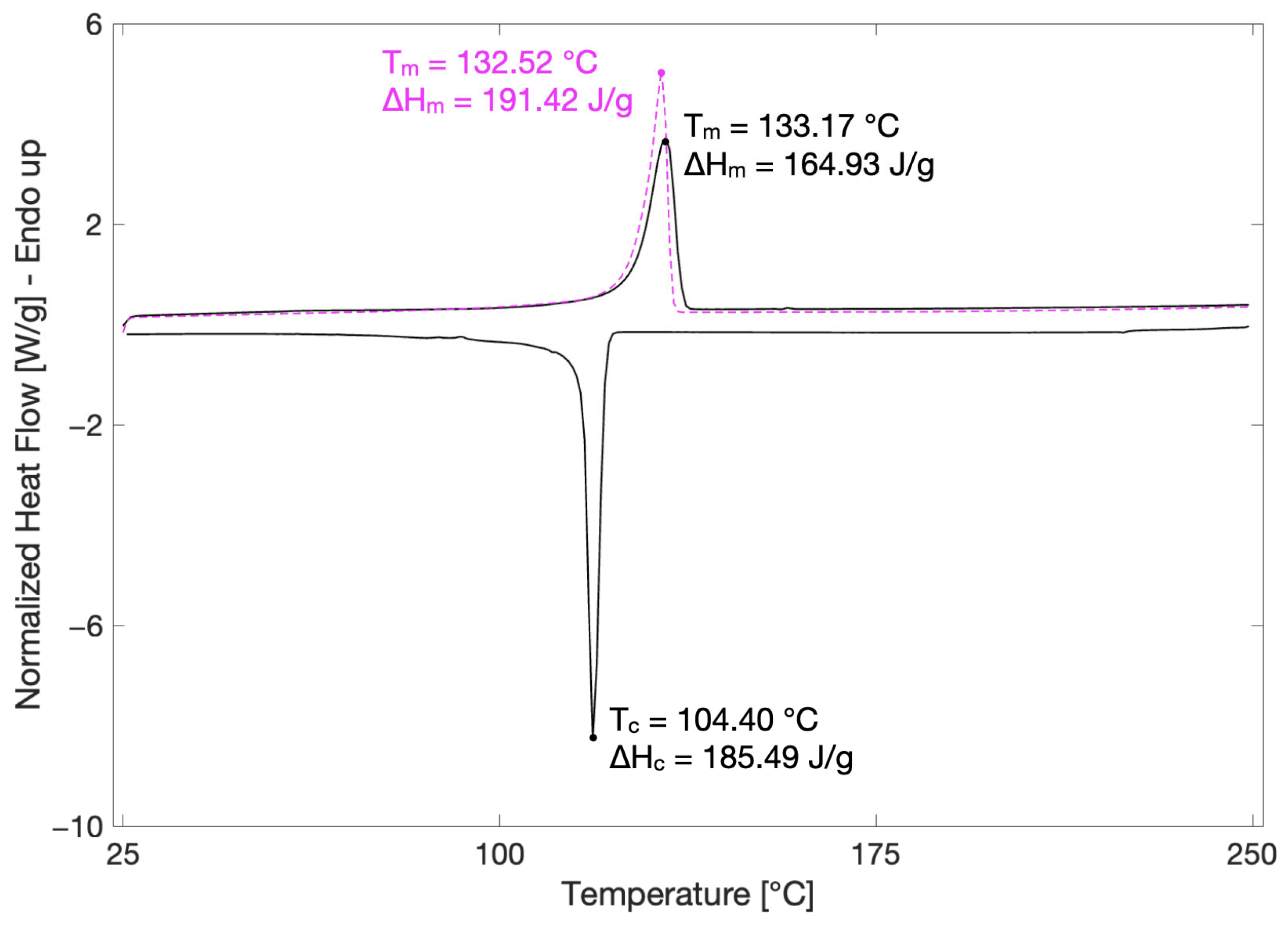
| Transition | Temperature [°C] | Enthalpy [J/g] |
|---|---|---|
| Melting peak—1st heating | 133.17 ± 0.68 | 164.93 ± 12.08 |
| Melting peak—2nd heating | 132.52 ± 0.44 | 191.42 ± 6.75 |
| Crystallization peak | 104.40 ± 0.56 | 185.49 ± 4.26 |
| Process Parameter | Value |
|---|---|
| Printing temperature | 230 °C |
| Build plate temperature | 60 °C |
| Printing speed | 50 mm/s |
| Infill pattern | Concentric |
| Infill density | 10% |
| Layer thickness | 0.2 mm |
Disclaimer/Publisher’s Note: The statements, opinions and data contained in all publications are solely those of the individual author(s) and contributor(s) and not of MDPI and/or the editor(s). MDPI and/or the editor(s) disclaim responsibility for any injury to people or property resulting from any ideas, methods, instructions or products referred to in the content. |
© 2025 by the authors. Licensee MDPI, Basel, Switzerland. This article is an open access article distributed under the terms and conditions of the Creative Commons Attribution (CC BY) license (https://creativecommons.org/licenses/by/4.0/).
Share and Cite
De Rosa, F.; Laurenzi, S. Printability Optimization of LDPE-Based Composites for Tool Production in Crewed Space Missions: From Numerical Simulation to Additive Manufacturing. Aerospace 2025, 12, 530. https://doi.org/10.3390/aerospace12060530
De Rosa F, Laurenzi S. Printability Optimization of LDPE-Based Composites for Tool Production in Crewed Space Missions: From Numerical Simulation to Additive Manufacturing. Aerospace. 2025; 12(6):530. https://doi.org/10.3390/aerospace12060530
Chicago/Turabian StyleDe Rosa, Federica, and Susanna Laurenzi. 2025. "Printability Optimization of LDPE-Based Composites for Tool Production in Crewed Space Missions: From Numerical Simulation to Additive Manufacturing" Aerospace 12, no. 6: 530. https://doi.org/10.3390/aerospace12060530
APA StyleDe Rosa, F., & Laurenzi, S. (2025). Printability Optimization of LDPE-Based Composites for Tool Production in Crewed Space Missions: From Numerical Simulation to Additive Manufacturing. Aerospace, 12(6), 530. https://doi.org/10.3390/aerospace12060530