Article

Study of Space Micro Solid Thruster Using 3D-Printed Short Glass Fiber Reinforced Polyamide

1
School of Mechanical Engineering, Nanjing University of Science and Technology, Nanjing 210094, China
2
China Academy of Launch Vehicle Technology, Beijing 100076, China
3
Xi’an Institute of Optics and Precision Mechanics of CAS, Xi’an 710119, China
*
Author to whom correspondence should be addressed.
Aerospace 2025, 12(8), 663; https://doi.org/10.3390/aerospace12080663 (registering DOI)
Submission received: 25 June 2025 / Revised: 18 July 2025 / Accepted: 22 July 2025 / Published: 26 July 2025

Abstract

To meet the rapid maneuverability and lightweight demands of micro-nano satellites, a space micro solid thruster using 3D-printed short glass fiber reinforced polyamide 6 (PA6GF) composites was developed. Thruster shells with wall thicknesses of 4, 3, and 2.5 mm were designed, and ground ignition tests were conducted to monitor chamber pressure and shell temperature. Compared with conventional metallic thrusters, PA6GF composites have exhibited excellent thermal insulation and sufficient mechanical strength. Under 8 MPa and 2773 K ignition conditions, the shell thickness was reduced to 2.5 mm and could withstand pressures up to 10.37 MPa. These results indicate that PA6GF composites are well-suited for space micro solid thrusters with inner diameters of 15–70 mm, offering new possibilities for lightweight space propulsion system design.

1. Introduction

In recent years, the number of launches of micro-nano satellites has increased dramatically, driven by the advantages of small size, light weight, low cost, and short development cycle [1,2]. At the same time, the performance, lifetime, functional density, and maneuverability of micro-nano satellites have also been significantly improved, and the complexity of the tasks they perform has also increased. Some micro-nano satellites require fast maneuverability to cope with the increasingly complex on-orbit missions. Solid propulsion is simple, responsive, reliable, and suitable for the rapid maneuvering needs of micro-nano satellites [3,4].
Micro-nano satellites have stringent requirements on the spatial layout and quality control of internal subsystems, and the lightweight design of their structures is a critical research focus [5]. Currently, micro-nano space solid thrusters developed domestically and internationally primarily utilize metallic materials [6,7,8,9], and there are two reasons for this status. One is that space micro solid thrusters generally have a short working time, and safety can be ensured by increasing the shell thickness without the need for thermal insulation design when using metallic material design. The second is that space micro solid thrusters are usually small in size and low in aspect ratio, and the application of fiber-wound composites as the shell is costly with little gain in weight reduction.
Metallic material design solutions have a simple design process and reliable products. However, due to the large shell thickness, the metal material design solution will bring large negative mass. In the field of lightweight design of small-scale structures, 3D printing technology has special advantages. 3D printing technology enables the fabrication of models with complex geometrical features [10] and has increasingly become a primary method for producing critical complex structures in the aerospace field in recent years [11]. Whitmore et al. used FDM technology to print ABS structures that serve as both fuel and solid-liquid thruster structures, and the results of the experimental tests showed that four 3D-printed ABS fuel hybrid rocket thrusters could provide a velocity increment of about 90 m/s for a three-unit CubeSat [12,13]. Hui et al. used SLS technology to 3D print nylon 12/glass bead reinforced composites (PA12GB) and developed a small solid thruster. Ground test results demonstrated that under ignition conditions of 12 MPa, 2773 K, and a total operation time of 70 ms, the thruster shell thickness could be reduced to as thin as 2mm [14,15]. The 3D printing technology combined with new materials provides a new design idea for solid propulsion in space.
Selective laser sintering (SLS) printing technology is one of the most popular 3D printing technologies, which is not only compatible with the processing of polymers and metals, but also the quality of the printed structures is superior [16]. Compared to metal materials, short glass fiber reinforced polyamide 6 (PA6GF) composites have lower costs and can be produced using SLS technology to manufacture complex internal parts. Compared to the PA12 composites used in references [14,15], PA6GF has better strength and excellent thermal insulation performance. In this work, a space micro solid thruster design is proposed using PA6GF composites, and the application space of PA6GF composites is investigated by combining the ignition experiment results of thrusters with different shell thicknesses and the design process.

2. Design and Experiment

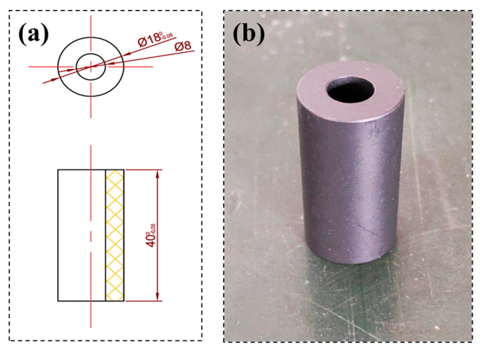
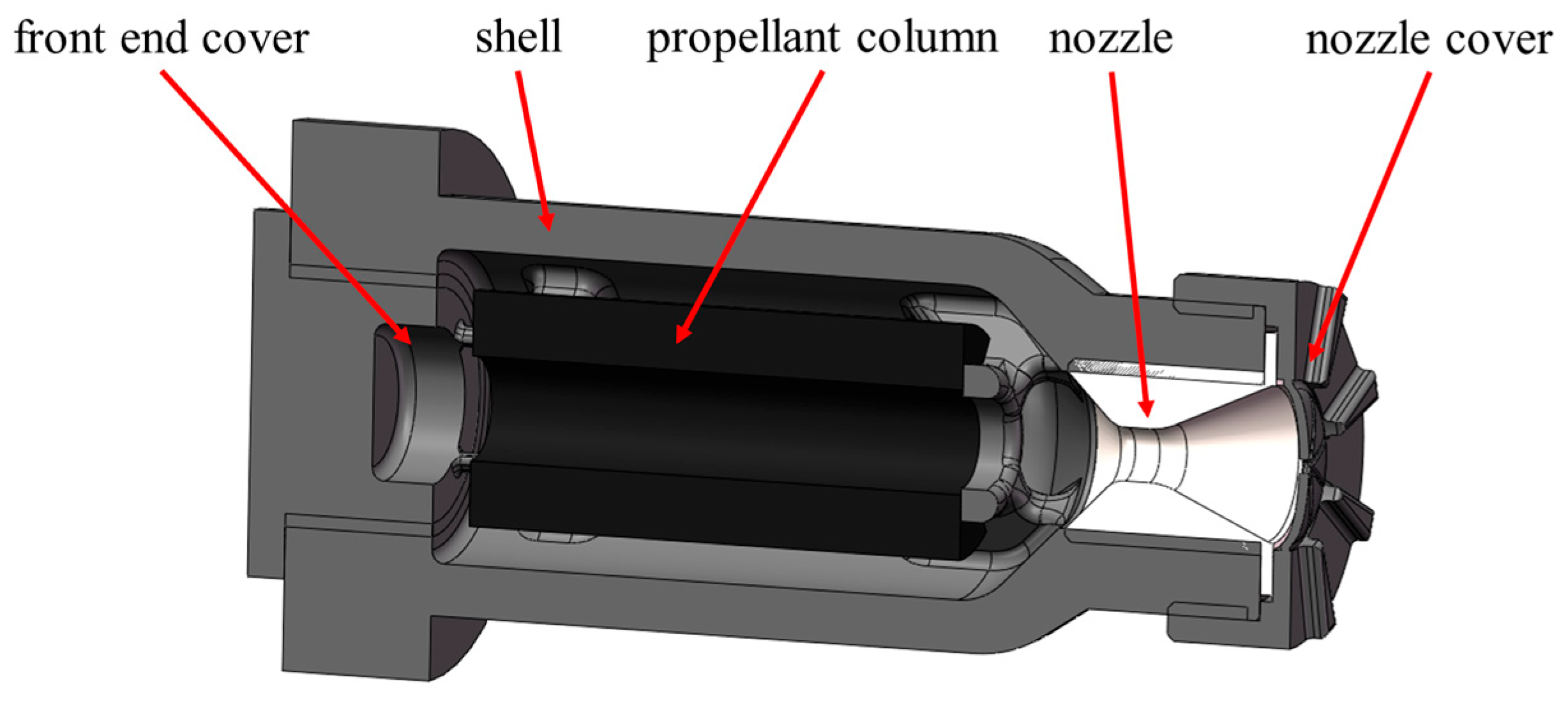
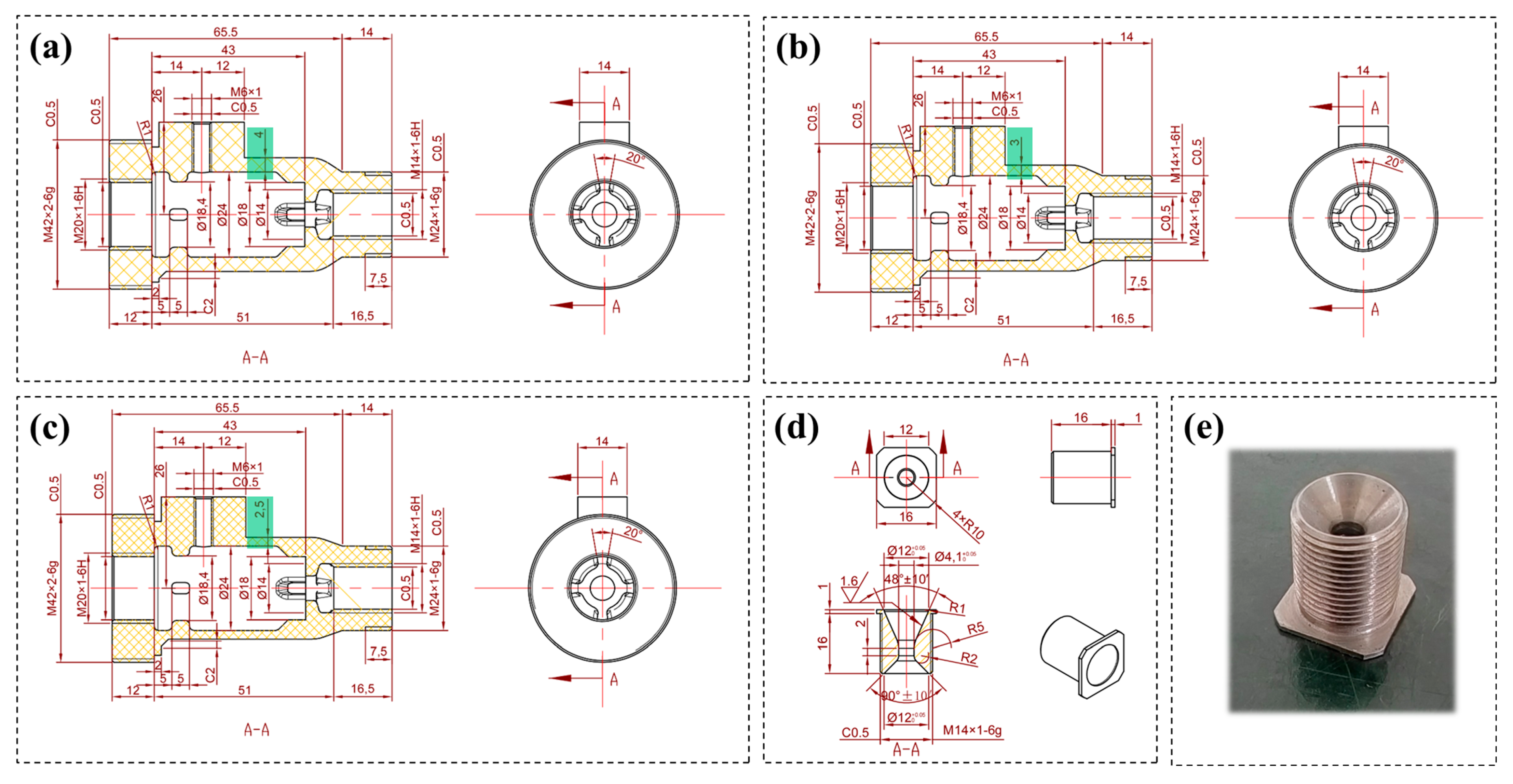
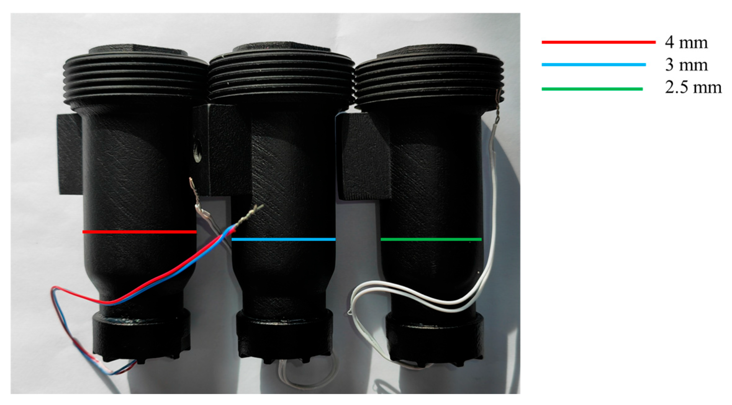
2.1. Solid Thruster Design

The material of the main structure of the thruster is PA6GF composite. Selected material parameters are shown in Table 1. The raw material powder of PA6GF composite material comes from Farsoon Technologies Co., Ltd. (Changsha, China), and the SLS process 3D printer model is Farsoon HT403P. The SLS printing parameters of the equipment are as follows: layer thickness of 0.1 mm, laser power of 140 W, scanning speed of 20 m/s, printing temperature of 186 °C, and piston temperature of 150 °C. Double cobalt-2 was chosen as the solid propellant for the thruster prototype, and the dimensions and physical appearance are shown in Figure 1. The designed space micro solid thruster consists of a front-end cover, shell, propellant column, nozzle, and nozzle cover, as shown in Figure 2. The material of the nozzle manufactured by conventional machining is 30CrMnSiA steel. All other parts were fabricated from PA6GF composite material by the SLS technique.
A schematic of some of the parts is shown in Figure 3. The shell serves as the main structure connecting the other parts to the fixture, where 6 mm threaded holes are used to connect the pressure sensors and 42 mm threaded holes are used to connect the fixture. The threads were obtained by machining the 3D-printed blanks. In this study, the shell wall thickness is the decisive parameter for the safety of the thruster. The wall thickness of the solid thruster can be calculated by Equations (1)–(3) [17].
δ m i n p m r i 2   σ 3 p m 2 2 p m r i 2.3   σ   p m
p m = K p p m
σ = σ s / n
In the above equation, p m is the combustion chamber jump pressure; r i is the inner radius of the combustion chamber shell, which is 12 mm; σ is the material allowable stress; σ s is the maximum tensile strength of the material, which is 67.5 MPa; n is the factor of safety, in this article to take 1.15; K p is the pressure jump coefficient, caused by the charge and parts of the manufacturing tolerance, the general take the value of 1.1 ~ 1.2, in this article to take 1.2; p m is the maximum working pressure, in this article to take 8 MPa. Substituting the data to calculate the minimum thickness of the PA6GF composite shell is 1.83 mm. PA6GF composites produced by SLS technology usually have microscopic pores. Considering the safety of solid thrusters, the solid thrusters in this work are designed with three shell thicknesses of 4 mm, 3 mm and 2.5 mm.

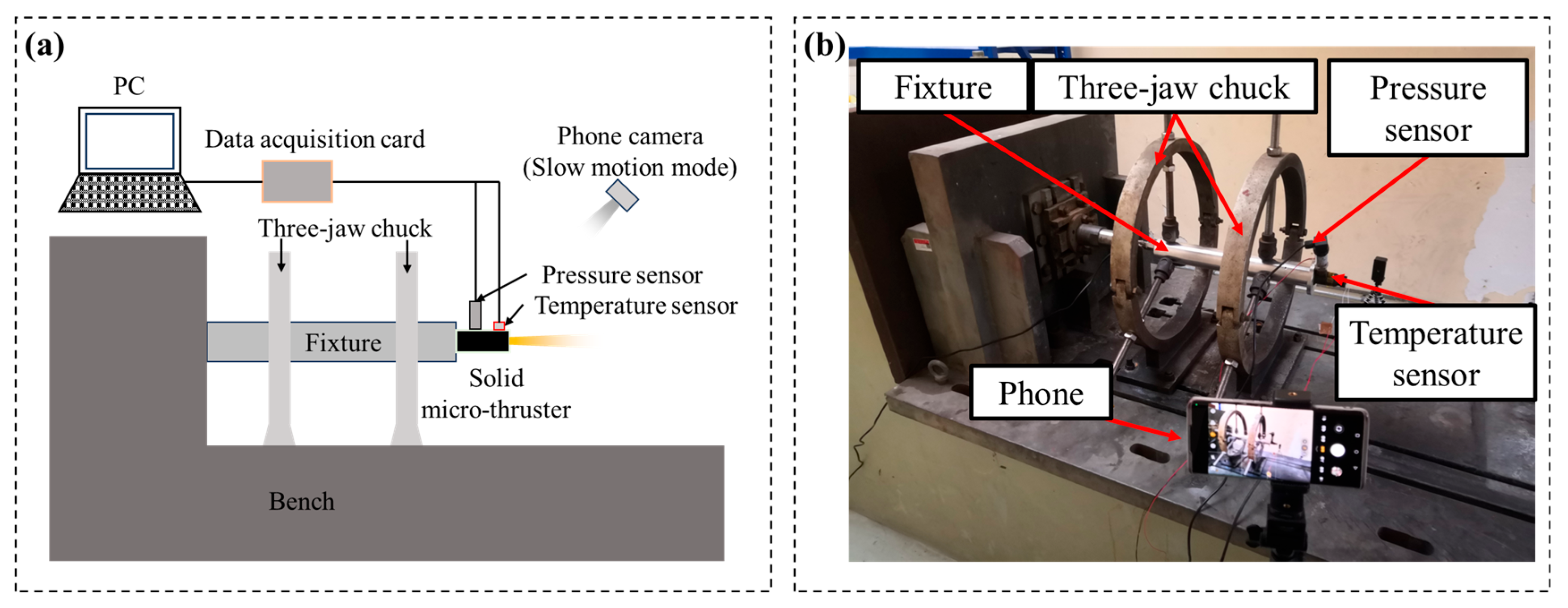
2.2. Experimental Techniques

The space solid thruster ground ignition experiment system is shown in Figure 4, which mainly includes three parts: horizontal thrust experiment bench, experiment thruster, and measurement and acquisition system. The horizontal thrust experiment bench uses two three-jaw chucks to hold the fixture in the center of the chuck, and the experiment thruster is installed at the end of the fixture; the test and acquisition system mainly includes a pressure sensor, video recording equipment, thermal resistance, a data acquisition card, and a computer. The model of the pressure sensor is LU-THG09PC10U1, with a range of 15 MPa. It is fixed on the thruster through the mechanical interface and adapter reserved in the combustion chamber. The thermal resistor model is PT1000, which is attached to the outer wall of the combustion chamber and covered with vacuum silicon insulation cotton to minimize the influence of the ignition gas plume on the outer shell temperature data.
A total of six space micro solid thrusters were used in the experiment, which were divided into three groups according to the shell thickness of the combustion chambers, with two in each group. The first group had a shell thickness of 4 mm, the second group had a shell thickness of 3 mm, and the third group had a shell thickness of 2.5 mm. Figure 5 shows the three groups of thrusters, and their average mass after assembly was 89 g, 86 g, and 83 g. Based on engineering experience [9], the first and second groups were ignited with 0.5 g of black powder, while the third group was ignited with 0.5 g of ignition powder and 1.0 g of ignition powder, and the 1.0 g of ignition powder thrusters were designed to increase the ignition pressure for testing the ultimate performance of the 2.5 mm shell thickness combustion chambers. By analyzing the three sets of tests against each other, the design law and the effect of shell thickness on the thermal insulation performance are explored. It is worth noting that the composite structure of the thruster took only 8 days from ordering to the completion of thread machining, which significantly improved the production efficiency. The total manufacturing cost of a single thruster was accounted to be about ¥ 800, demonstrating good economics.

3. Results and Discussion

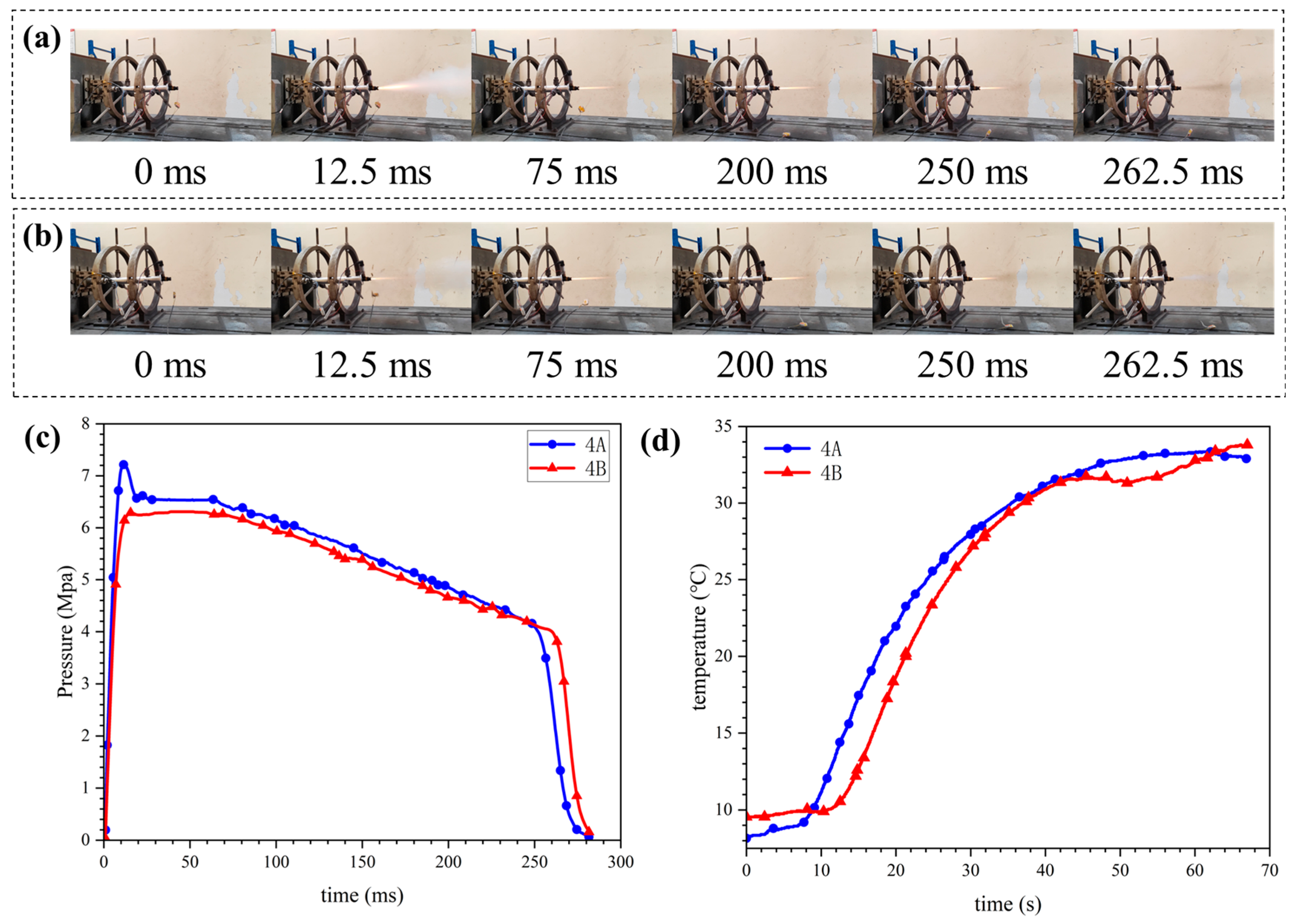
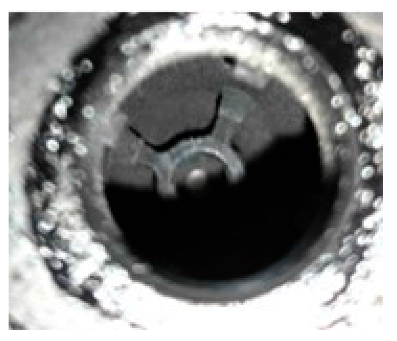
3.1. 4 mm Shell Thickness Solid Thruster Ignition Experiment

Two PA6GF composite thrusters with a wall thickness of 4 mm are numbered 4A and 4B. The ignition experiment process is shown in Figure 6a,b. From the 12.5 ms image, it can be seen that the 4A thruster has a higher ignition pressure. After ignition, the tail flame of the 4A and 4B thrusters is stable during operation, and the working time is similar. The pressure curves during the test are shown in Figure 6c, with the maximum combustion chamber internal pressure of 7.286 MPa for the 4A thruster and 6.448MPa for the 4B thruster, and the operating time of both thrusters is around 280 ms. The outer shell surface temperatures of the thrusters during the ignition period are shown in Figure 6d, and the hottest temperatures of the shells after ignition are both around 33 °C. The states of the front-end cover and the propellant support structure in the combustion chamber after ignition are shown in Figure 7. The inner surface of the front-end cap experienced more severe gas scouring, and the propellant column fixing legs were not completely burned. The integrated support structure overhanging the inner shell of the combustion chamber is still clearly recognizable by its geometric features.

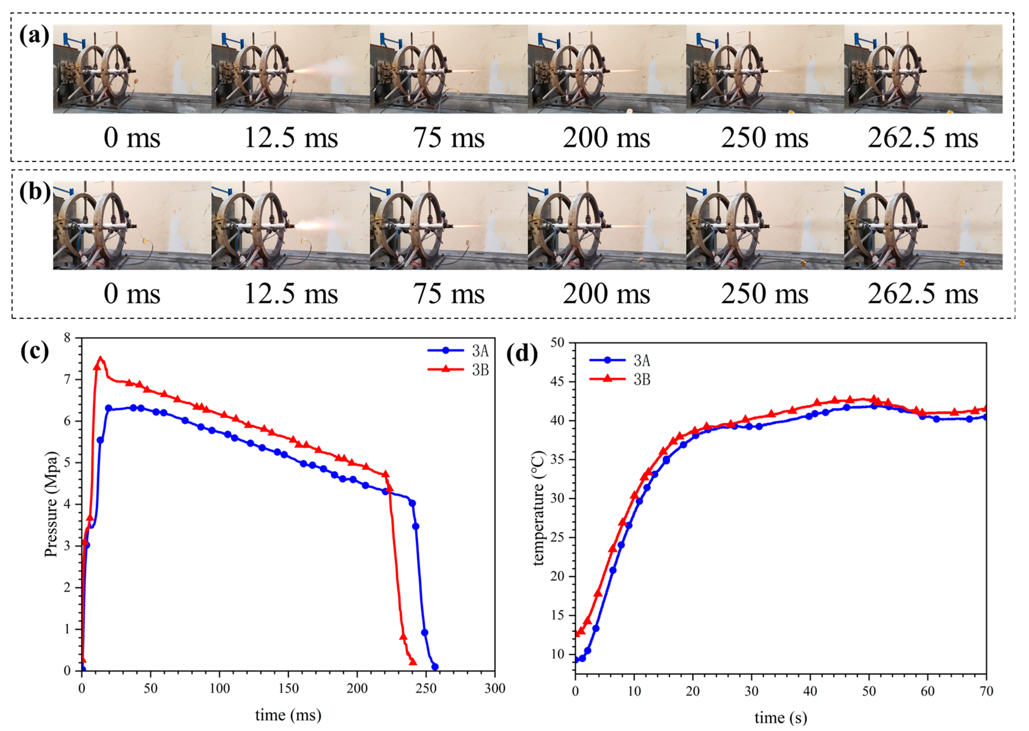
3.2. 3 mm Shell Thickness Solid Thruster Ignition Experiment

Two PA6GF composite thrusters with a wall thickness of 4mm are numbered 3A and 3B. The ignition experiment process is shown in Figure 8a,b. From the 12.5 ms image, it can be seen that the ignition flame of the 3B thruster is larger and the ignition pressure is higher. From the 250 ms image, it can be seen that due to the higher ignition pressure, the working time of the 3B thruster is shorter. The pressure profiles during the test are shown in Figure 8c, with the maximum combustion chamber internal pressure of 6.44 MPa for the 3A thruster and 7.54 MPa for the 3B thruster. The operating time of the 3A thruster was around 280 ms, and that of the 3B thruster was around 265 ms. The temperatures of the outer shell surface of the thrusters during the ignition period are shown in Figure 8d. The highest temperatures of the shells after ignition are around 42 °C, which is higher than 33 °C for the 4-mm shell thickness thruster, but the temperatures of the outer shell surfaces are almost unchanged in the same operating moment. A 3-mm shell thickness of the PA6GF composite combustion chamber is sufficient to withstand the short-term high-force thermal load impact brought by the gas. The maximum temperature of the outer shell surface after ignition increased significantly after the shell thickness was reduced.

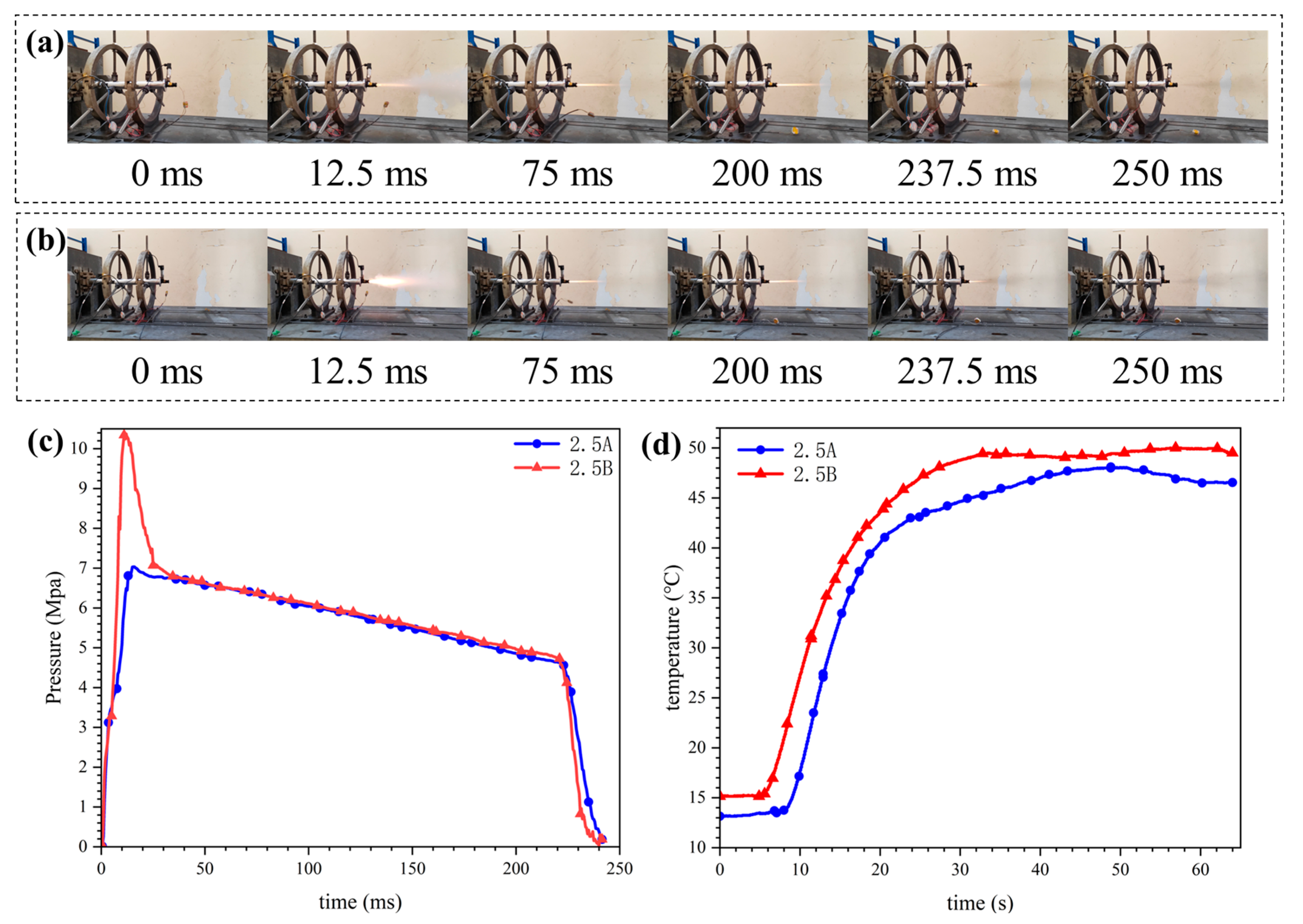
3.3. 2.5 mm Shell Thickness Solid Thruster Ignition Experiment

Two PA6GF composite thrusters with a wall thickness of 4mm are numbered 2.5A and 2.5B The ignition package inside the 2.5B thruster uses 1 g of black powder to investigate the ultimate pressure-bearing performance of the PA6GF composite combustion chamber. The ignition experiment process is shown in Figure 9a,b. From the 12.5 ms image, it can be seen that the ignition flame of the 2.5B thruster is very bright, and some ignition powder failed to ignite in the combustion chamber, resulting in ignition energy loss. The working time of the 2.5A and 2.5B thrusters is basically the same. The pressure curves during the test are shown in Figure 9c, with the maximum combustion chamber internal pressure of 7.11 MPa for the 2.5A thruster and 10.37 MPa for the 2.5B thruster. The operating time of both is around 240 ms. The temperatures of the outer shell surface of the thrusters during the ignition time are shown in Figure 9d, and the highest temperatures of the shells after ignition are both around 50 °C, which are higher than those of the thrusters with shell thicknesses of 4 mm and 3 mm, but the temperatures of the outer shell surfaces are almost unchanged at the operating instant. There is a correlation between the shell thickness and the maximum temperature of the outer shell surface at the end of ignition. The 2.5B thruster has been subjected to 10.37 MPa, and the inner shell surface after ignition is shown in Figure 10, which can be seen to be like the state of the inner shell surface in Figure 7a. Under the internal ballistic conditions in this work, the 2.5 mm shell thickness PA6GF composite shell is also able to withstand the short-duration, high-force thermal load impact from the gas, corresponding to a design safety factor of 1.4.

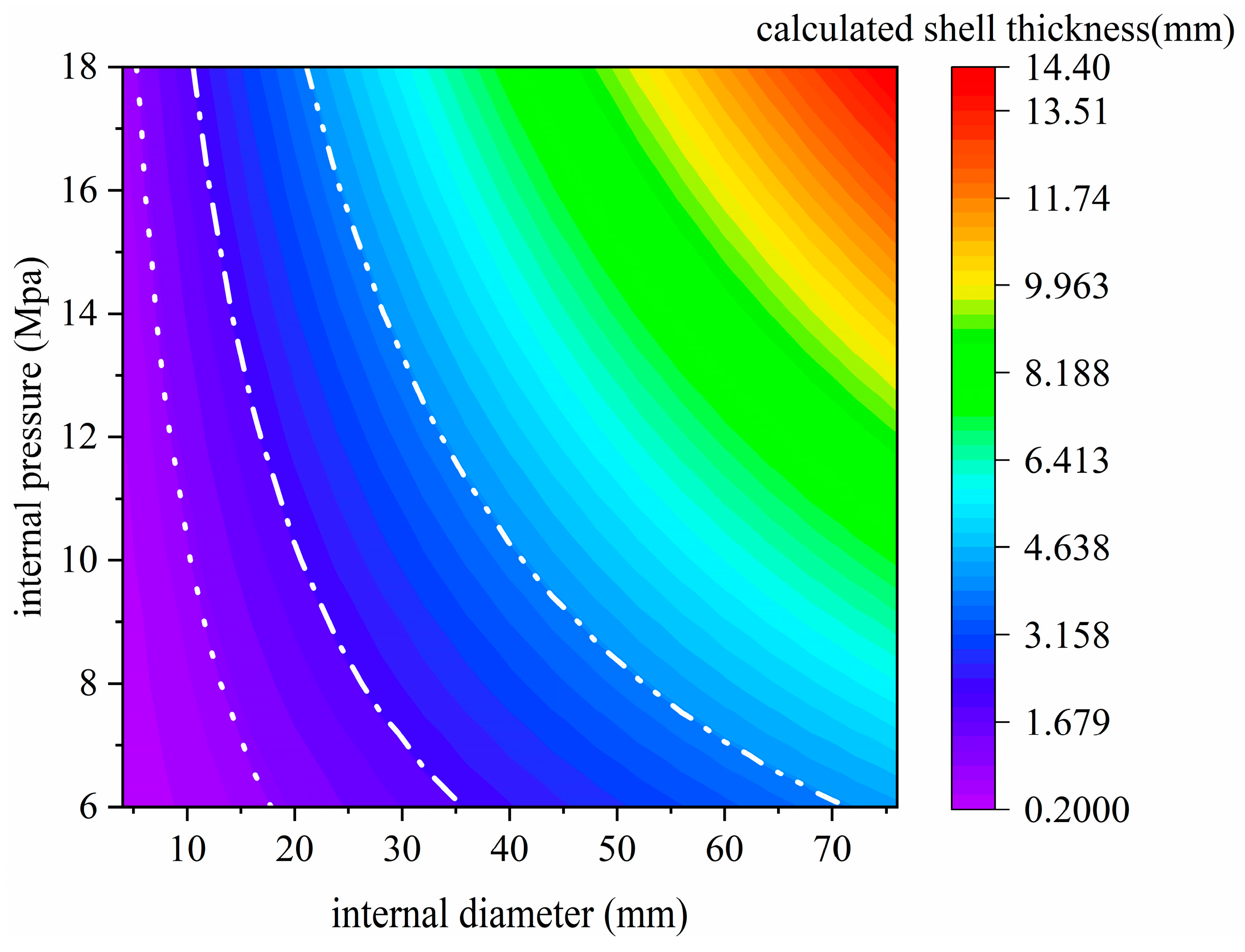
3.4. PA6GF Composite Material Applicable Design Range

In the literature [12], the SLS process PA12GB composite solid booster was designed with an inner diameter of 10.5 mm and a maximum ignition pressure of 12.15 MPa. According to the official data of HP, the maximum tensile ultimate strength of PA12GB composite is 33 MPa. By substituting the thruster’s inner diameter, internal pressure, and material parameters into Equations (1)–(3), it can be concluded that only when both the safety factor and the pressure fluctuation coefficient are set to 1 does the calculated wall thickness reach 2 mm. This shows that the polyamide composite thruster can still work reliably under extreme design conditions. In actual engineering, considering the errors in the production process and the unexpected situation in the solid propellant combustion, it is more adventurous to take these two parameters as 1 for the design, so a safer design range is needed.
In this study, the 2.5 mmPA6GF composite thruster combustion chamber has a safety coefficient of 1.15 and a pressure jump coefficient of 1.2 at an internal pressure of 10.37 MPa. If these two coefficients are taken to be 1, the calculated shell thickness is only 1.8 mm, and the actual shell thickness is greater than the limiting calculated shell thickness of 0.7 mm. The results of the ignition experiment show that the highest temperature of the outer shell surface of the thrusters after ignition is only 50 °C and the geometric features of the charge support structure made in one piece on the inner shell surface of the chamber are clearly visible, and the actual ablation rate is very low. The geometrical characteristics of the charge support structure made in one piece on the inner shell are clearly visible, and the actual ablation rate is very low. These results lead to the conclusion that PA6GF composites have excellent thermal insulation capabilities and are somewhat resistant to ablation. For space micro solid thruster with very short operating time, if PA6GF composites are used as the shell material, the design shell thickness only needs to be taken slightly increase to meet the thermal insulation requirement of the space solid thruster.
Metallic space micro solid thrusters also utilize increased design shell thickness to meet the thermal insulation needs of space solid thrusters. However, due to the good thermal conductivity of metal materials, there is a significant increase in the design wall thickness. Taking the study in literature [8] as an example, the designed space solid thruster has a maximum internal pressure of 15.1 MPa, an inner diameter of 28 mm in the combustion chamber, a safety factor of 1.15, and a pressure jump factor of 1.2, the calculated shell thickness is only 0.29 mm by Equations (1)–(3). However, the final design shell thickness of the actual program is 2 mm, which is inversely solved to a safety factor of 7.5.
The above analysis indicates that when designing space micro solid thrusters using metallic materials, the design wall thickness must be several times greater than the calculated thickness. Only then can the combustion chamber made of metal safely withstand the thermo-mechanical loads induced by the combustion gases during thruster operation. When a polyamide composite design is used, the polyamide composite combustion chamber can safely carry the force-heat loads from the gas during thruster operation with only a slight increase in the design shell thickness. The comprehensive design process of the shell thickness selection process and polyamide composite materials work with thermal shock impact thickness, which can be seen when the safety factor is 1.15 and the pressure jump coefficient is 1.2 when the calculated shell thickness is greater than the safety factor of 1 and the pressure jump coefficient is 1 when the limit of the shell thickness of the value is larger. The extra thickness can be used as the “slightly increased” design shell thickness to meet the thermal insulation requirements of the thruster, increase the strength of the entire combustion chamber structure, and ensure the reliability and safety of the solid thruster. The polyamide composite structure can satisfy the strength and thermal insulation requirements of the thruster at the same time.
The following combines the design formula to compare the weight reduction effect of PA6 composites. The safety coefficient is taken as 1.15, and the pressure jump coefficient is taken as 1.2, and the inner pressure of 8 MPa and inner diameter of 24 mm are taken as the design index of the thruster in this work. As shown in Table 2, if we use LC4 aluminum alloy, TC6 titanium alloy, and 30CrMnSiA steel to carry out the combustion chamber design work, the calculated shell thicknesses of the three metal materials are 0.3 mm, 0.135 mm, and 0.131 mm, respectively. Based on the experience of the design of the solid metal material thrusters without a heat insulation layer, the actual shell thickness selection is greater than the calculated value. The wall thickness of the TC6 thruster will be around 0.8 mm. Under the conditions of this section, the wall thickness of the LC4 and 30CrMnSiA thrusters needs to be larger, here taken as 2 mm and 1.5 mm. The middle part of the combustion chamber is similar to a hollow cylinder, and only calculating the mass of the 45 mm cylinder section of the combustion chamber, we get that the LC4 shell is 20.6 g, the TC6 shell is 12.7 g, and the 30CrMnSiA shell is 42.18 g. The 2 mm shell thickness of the PA6GF composite shell is 10.3 g. PA6GF composites are able to be used in the design of solid thrusters without a heat insulation layer, and the shell thickness is 0.131 mm. PA6GF composites can be used in the case of higher shell thicknesses than titanium alloy TC6, and at twice the shell thickness of metal shells, i.e., between 2 mm and 5 mm, PA6GF shells with cylindrical segments reduce weight by 18.8% compared to TC6 and 75.5% compared to 30CrMnSiA. The PA6GF composites have obvious gains in weight reduction. Meanwhile, the test results show that PA6GF composites have excellent thermal insulation performance. If the space solid thruster configuration for more than one ignition unit composed of an array, PA6GF composite materials manufactured by a single ignition unit in the ignition of the neighboring ignition unit after the impact will be less than the metal materials manufactured by the ignition unit array.
Different combustion chamber materials, internal diameters, and pressures can lead to different calculated shell thicknesses. Solid propulsion mode is different according to the type of charge; the internal pressure of the combustion chamber ranges from 6 MPa to 18 MPa, and the diameter envelope size of space micro solid thrusters is usually required to be less than 100 mm. According to this information and the tensile ultimate strength of PA6GF composite material, the safety factor is taken to be 1.15, and the pressure jump coefficient is taken to be 1.2, and a series of relationships among the internal pressure, the internal diameter, and the shell thickness can be obtained from Equations (1)–(3) The specific situation is shown in Figure 11. The horizontal and vertical coordinates in the figure are the internal diameter and internal pressure, and the color corresponds to the calculated shell thickness on the legend, so you can visualize the correspondence between these three values. 3D printing process, smaller geometric feature error, and quality are difficult to ensure. The minimum feature size of the SLS process is recommended to be 0.8 mm, so the design of the combustion chamber shell thickness should not be too low. The dotted line in the figure is the calculated shell thickness 1 mm contour, the single-dotted line is the calculated shell thickness 2 mm contour, and the double-dotted line is the calculated shell thickness 4 mm contour. From Figure 11, it was found that PA6GF composites are more suitable for the space micro solid thruster with an inner diameter of less than 70 mm. When the inner diameter of the thruster is less than 35 mm, the pressure can be adjusted in a wide range. When the inner diameter is further reduced to less than 15 mm, the calculated shell thickness will be less than 1 mm, which is unfavorable for the actual part manufacturing.

4. Conclusions

This work provides new ideas for the lightweight design of space micro solid thrusters by designing the space micro solid thruster using 3D-printed PA6GF composite materials and conducting ignition experiment analysis and research with different shell thicknesses, and the main conclusions are as follows:
(1) PA6GF composites fabricated using 3D printing technology can be applied to the design and development of space micro solid thrusters. The thruster design proposed in this study can withstand an ignition pressure of 10.37 MPa and an ignition gas temperature of 2773 K. Under the design specifications of 8 MPa internal pressure in the combustion chamber, 2300 K gas temperature, and 300 ms operating time, there is still a certain safety margin to reduce the shell thickness of the thruster to 2.5 mm.
(2) PA6GF composite material has excellent thermal insulation performance; in the external temperature conditions of 10 °C, 2.5 mm thrusters in the ignition of the outer shell surface temperature go up to only 50 °C. PA6GF composite material also has a certain degree of resistance to erosion; the front cover and the combustion chamber shell surface after ignition of the geometric features are still clearly distinguishable.
(3) In a certain working time and geometry, the 3D printing PA6GF composite material program proposed in this work has obvious advantages. Combined with the test results and the design process, it can be seen that PA6GF composites are more suitable for space micro solid thrusters within the range of 15~70 mm inner diameter, while the working time should not be too long. Compared with the traditional metal material space micro solid thruster scheme, the 3D-printed PA6GF composite material scheme proposed in this work reduces the mass and improves structural integration.

Author Contributions

Conceptualization, H.Y.; methodology, X.Y.; software, X.Y.; validation, X.Y., C.X. and H.D.; formal analysis, X.Y.; investigation, X.Y.; resources, H.Y.; data curation, X.Y.; writing—original draft preparation, H.Y. and X.Y.; writing—review and editing, Z.C., C.X. and H.D.; visualization, X.Y. and C.X.; supervision, H.Y.; project administration, H.Y. All authors have read and agreed to the published version of the manuscript.

Funding

This research received no external funding.

Data Availability Statement

The original contributions presented in the study are included in the article.

Acknowledgments

Thanks to the Micro-nano Satellite Research Center of Nanjing University of Science and Technology for their support and help in this exploratory project.

Conflicts of Interest

The authors declare no conflicts of interest.

Abbreviations

The following abbreviations are used in this manuscript:
PA6GFShort glass fiber reinforced polyamide 6 composites
PA12GBNylon 12 reinforced whit glass bead reinforced composites
FDM3D print technology, fused deposition modeling
SLS3D print technology, selective laser sintering

References

  1. Poghosyan, A.; Golkar, A. CubeSat evolution: Analyzing CubeSat capabilities for conducting science missions. Prog. Aerosp. Sci. 2017, 88, 59–83. [Google Scholar] [CrossRef]
  2. Shkolnik, E.L. On the verge of an astronomy CubeSat revolution. Nat. Astron. 2018, 2, 374–378. [Google Scholar] [CrossRef]
  3. Krejci, D.; Lozano, P. Space propulsion technology for small spacecraft. Proc. IEEE 2018, 106, 362–378. [Google Scholar] [CrossRef]
  4. Holler, M. Coping with space environment: Testing solid propellants for in-orbit use. Int. J. Energetic Mater. Chem. Prop. 2023, 22, 45–66. [Google Scholar] [CrossRef]
  5. Liao, W.; Dai, N. Development and challenge of lightweight design and manufacturing technology for aerospace structures. J. Nanjing Univ. Aeronaut. Astronaut. 2023, 55, 347–360. [Google Scholar]
  6. Okninski, A. Solid rocket propulsion technology for de-orbiting spacecraft. Chin. J. Aeronaut. 2022, 35, 128–154. [Google Scholar] [CrossRef]
  7. Faber, D.; Overlack, A.; Welland, W.; van Vliet, L.; Wieling, W.; Tata Nardini, F. Nanosatellite Deorbit Motor. 2013. Available online: https://digitalcommons.usu.edu/smallsat/2013/all2013/51/ (accessed on 1 July 2025).
  8. Nowakowski, P.; Pakosz, M.; Okninski, A.; Rysak, D.; Kaniewski, D.; Marciniak, B.; Surmacz, P.; Kasztankiewicz, A.; Szczepanik, M.; Matlok, A. Design of a solid rocket motor for controlled deorbitation. In Proceedings of the 53rd AIAA/SAE/ASEE Joint Propulsion Conference, Atlanta, GA, USA, 10–12 July 2017. [Google Scholar]
  9. Bi, Y. Design and Research of Solid Thruster Array for Micro/Nano Satellite. Master’s Thesis, Nanjing University of Science & Technology, Nanjing, China, 2021. [Google Scholar]
  10. Ngo, T.D.; Kashani, A.; Imbalzano, G. Additive manufacturing (3D printing): A review of materials, methods, applications and challenges. Compos. Part B Eng. 2018, 143, 172–196. [Google Scholar] [CrossRef]
  11. Pant, M.; Pidge, P.; Nagdeve, L. A Review of Additive Manufacturing in Aerospace Application. J. Compos. Adv. Mater. Rev. Compos. Matériaux Avancés 2021, 31, 109. [Google Scholar] [CrossRef]
  12. Whitmore, S.A. Consumable spacecraft structures with integrated, 3-D printed ABS thrusters. In Proceedings of the 53rd AIAA/SAE/ASEE Joint Propulsion Conference, Atlanta, GA, USA, 10–12 July 2017. [Google Scholar]
  13. Whitmore, S.A. Additively manufactured acrylonitrile-butadiene-styrene–nitrous-oxide hybrid rocket motor with electrostatic igniter. J. Propuls. Power 2015, 31, 1217–1220. [Google Scholar] [CrossRef]
  14. Hui, W.; Hu, Y.; Liu, Y.; Cai, Q.; Zhao, W. Ablation characteristics research in solid rocket motor’s combustion chamber produced by 3D printing. Materials 2023, 16, 3021. [Google Scholar] [CrossRef]
  15. Hui, W.; Hu, Y.; Liu, Y.; Cai, Q.; Zhao, W. Development of thin-walled polymer glass beads reinforced 3D printed solid rocket motors. Mater. Lett. 2023, 347, 134558. [Google Scholar] [CrossRef]
  16. Morano, C.; Pagnotta, L. Additive manufactured parts produced using selective laser sintering technology: Comparison between porosity of pure and blended polymers. Polymers 2023, 15, 4446. [Google Scholar] [CrossRef]
  17. Zhou, C. Theory of Rocket and Missile Design, 1st ed.; Beijing Institute of Technology Press: Beijing, China, 2014. [Google Scholar]
Figure 1. Detailed drawings of propellant: (a): Dimensions, (b): Physical diagram.
Aerospace 12 00663 g001
Figure 2. Schematic diagram of the space solid thruster structure.
Aerospace 12 00663 g002
Figure 3. Schematic diagrams of some parts of the thruster: (a): 4 mm shell thickness of the thruster combustion chamber, (b): 3 mm shell thickness of the thruster combustion chamber, (c): 2.5 mm shell thickness of the thruster combustion chamber, (d): nozzle, (e): nozzle physical diagram.
Aerospace 12 00663 g003
Figure 4. Ground ignition experiment system: (a): Schematic diagram, (b): Physical diagram.
Aerospace 12 00663 g004
Figure 5. The space micro solid thrusters physical diagram (4 mm, 3 mm, and 2.5 mm).
Aerospace 12 00663 g005
Figure 6. 4 mm shell thickness thruster ignition experiment: (a): 4A thruster ignition process, (b): 4B thruster ignition process, (c): Inner thruster pressure change curve, (d): Outer thruster shell temperature change curve.
Aerospace 12 00663 g006
Figure 7. (a): Combustion chamber interior after ignition of 4 mm thruster, (b): Front end cover after ignition of 4 mm thruster.
Aerospace 12 00663 g007
Figure 8. 3 mm shell thickness thruster ignition experiment: (a): 3A thruster ignition process, (b): 3B thruster ignition process, (c): Inner thruster pressure change curve, (d): Outer thruster shell temperature change curve.
Aerospace 12 00663 g008
Figure 9. 2.5 mm shell thickness thruster ignition experiment: (a): 2.5A thruster ignition process, (b): 2.5B thruster ignition process, (c): Inner pressure change curve of the thruster, (d): Outer shell temperature change curve of the thruster.
Aerospace 12 00663 g009
Figure 10. Inner shell of the combustion chamber of the 2.5B thruster that has withstood an internal pressure of 10.37 MPa.
Aerospace 12 00663 g010
Figure 11. Correspondence of internal pressure, internal diameter, and shell thickness of PA6GF composite.
Aerospace 12 00663 g011
Table 1. PA6GF Material Properties.
Parameter NameValue
Density (g/cm3)1.41
Tensile strength (MPa)67.5
Tensile modulus (MPa)5590
Thermal conductivity (W/m·K)0.56
Specific heat capacity (J/kg·K)1633
Melting point (°C)224
Table 2. Design shell thickness and mass of cylinder section for different materials under the ballistic design index in this article.
ParameterLC4TC630CrMnSiAPA6GF
Tensile ultimate strength (MPa)402>850>88367.5
Calculated shell thickness (mm)0.30.1350.1311.83
Actual selected shell thickness (mm)20.81.52
Mass of cylinder section (g)20.612.742.1810.3
Disclaimer/Publisher’s Note: The statements, opinions and data contained in all publications are solely those of the individual author(s) and contributor(s) and not of MDPI and/or the editor(s). MDPI and/or the editor(s) disclaim responsibility for any injury to people or property resulting from any ideas, methods, instructions or products referred to in the content.

