1. Introduction
Borescope inspection (BI) is widely employed in industries such as aviation, automotive, and marine. It is especially critical for inspecting aircraft engines since it allows internal components to be examined without necessitating engine disassembly. During the inspection, a borescope is inserted through specific ports that directly position the probe to view high-priority components—namely, the blades and vanes. These parts are vital for engine performance and are particularly susceptible to damage, often caused by foreign objects being ingested by the engine.
A key element of the inspection process involves precisely measuring the size and extent of any detected defects to determine whether they exceed allowable thresholds. Such measurements are essential for deciding if the engine can continue in operation or must be removed for repair.
The narrow dimensions of a borescope port place strict limitations on both the sensor and illumination hardware, as these must be compact enough to pass through the port. Current borescope measurement methods, primarily stereo cameras and pattern projection, face notable challenges. Stereo cameras, for instance, require sufficient texture or distinctive features on engine surfaces for accurate stereo matching, whereas pattern projection struggles with reflective or uneven surfaces frequently encountered in engines. Further complicating matters, the confined spaces within engines often make it difficult to project clear patterns or achieve accurate measurements.
Conventional measuring borescopes illuminate the entire inspection scene, but their maximum illumination intensity is constrained by the need to dissipate heat in a very limited space. Micro-electromechanical systems (MEMS)-based 3D scanners, on the other hand, can focus laser light into a small spot, thereby increasing the local illumination intensity and reducing dependence on surface texture. In addition, the projected pattern can be dynamically shifted, which aids in edge detection and improves measurement fidelity. Moreover, time-of-flight or phase-shift methods can be integrated into MEMS scanners, promising enhanced lateral and depth measurement accuracy. However, current MEMS scanners are typically too large to fit through standard aircraft engine inspection ports.
In this work, we develop a miniaturized MEMS-based 3D scanner tailored for borescope inspection. Our contributions are as follows:
First, we identify the key requirements of the target application and discuss appropriate measurement principles for a MEMS-based scanner.
We design a borescope head assembly that incorporates all necessary electrical and optical components—along with a control unit—sized to fit through engine inspection openings.
We investigate the MEMS mirror module and the optical setup and discuss an assembly strategy.
We explore the concept of a MEMS-based projector with a flexible pattern in combination with a stereo camera.
We examine laser-camera triangulation using the MEMS projection unit.
Finally, we develop the control unit and construct a borescope prototype that incorporates the aforementioned modules.
2. Literature Review
Since the 1950s, borescopes have been increasingly used for industrial inspection. The most widespread are imaging borescopes. The beams of light entering the optics of the borescope are either directly processed in the borescope head (distal end) by an imaging sensor (chip-on-the-tip) or processed externally through image guides such as optical fibers or lenses along the endoscope shaft.
Recent publications in the realm of borescope inspection have highlighted the advancements of novel borescope robots [
1,
2,
3,
4]. Bath et al. [
1,
2] have pioneered the creation of a continuum robot designed to autonomously guide a probe in a circular path during inspections. This innovation promises repeated and precise positioning of the borescope probe through inspection apertures with small dimensions. Robots of this nature could be instrumental in automating the inspection process of aircraft engine combustion chambers. However, their functionality is contingent upon integration with existing borescope sensor hardware.
2.1. 3D Borescope Measurement for the Inspection of Aircraft Engines
Maintenance plays a critical role in ensuring the airworthiness of aircraft and managing their operating costs. In today’s aviation, engines are maintained using a condition-based approach, known as on-condition maintenance, rather than fixed-time or fixed-interval methods.
Condition-based maintenance relies on periodic inspections or tests to trigger maintenance actions when predefined condition thresholds are met. Various methods, such as visual inspections, non-destructive testing (NDT), vibration monitoring, and borescope inspection (BI), are used for condition assessment. A BI involves inserting a camera-equipped tube into the engine to inspect internal components. Current trends in borescope inspection include the application of deep learning-based computer vision to borescope images [
5,
6,
7,
8,
9] in order to automate or assist with defect detection.
Guidelines for an aircraft engine’s BI are outlined in the Aircraft Maintenance Manual (AMM). After identifying issues like fissures or corrosive damage, defect dimensions must be measured. This is crucial because inspection implications depend not just on the defect type and location but also on the dimensions of the affected area. Borescopes with 3D measuring capabilities are used for three-dimensional quantification of the defect’s area and depth.
Borescope measurement systems, exemplified by the Mentor Visual IQ from Waygate Technologies, have become the standard for BIs. These flexible video borescopes allow for the capture of surface images displayed on a monitor and offer adjustable optics for various applications, enabling changes to the field of view and depth of field. For the 3D measurements, they rely on the principle of stereo vision [
10] and pattern projection [
11] to generate a 3D point cloud for a captured image. In addition to stereo vision, the product offers the option of using structured light to generate 3D information. In the phase measurement, a special stripe pattern is projected onto the component surface and recorded by the camera.
However, the accuracy of 3D measurements in real-world BI scenarios can be influenced by factors like lighting conditions, object–sensor distance, and surface quality, often leading to the accuracy deviating from the manufacturer’s stated values under ideal conditions and potentially decreasing the data quality [
11].
Stereo vision has several disadvantages that limit its application. Its accuracy is dependent on the illumination, the distance to the object, and the sensitivity to the texture of the inspected object. In borescope inspections, we encounter an insufficient field of view and a restricted field of depth for the used optics. In particular, objects that appear farther away from the probe cannot be measured with tolerable accuracy. These limitations are inherent to the physical operating principle of stereo vision.
State-of-the-art borescopes confront the limitations of 3D data accuracy by presenting users with a visual representation of potential inaccuracies, enabling them to choose measurement points with greater precision or to retake measurements as necessary. While this interactive feature enhances the accuracy of data, it also introduces a time-consuming process that is prone to errors and heavily dependent on the user’s expertise. The balance between user input and technological capability is crucial, as it demands both attentiveness and experience to ensure the integrity of the inspection results.
In pure stereo vision, the main problem is the registration of identical points in the different camera images (stereo matching). Matching is particularly critical in scenes with few prominent pixels. Projectors that apply artificial texturing can help. An efficient method that achieves precise registration even with non-coded, (pseudo-)random patterns is presented in [
12]. A significantly reduced computational effort is achieved with coded patterns, as with the aforementioned “Mentor Visual IQ”. An overview of various coding methods is presented in [
13]. The disadvantages of the more expensive hardware and reduced dynamics are offset by the significantly higher accuracy; registration does not have to be determined but can be “read” [
12].
Recent efforts aim to refine stereo and pattern projection techniques. Neil et al. [
14] have introduced a stroboscopic illumination method that minimizes pattern projection distractions during navigation and visual inspection tasks. In 2013, Aoki et al. [
15] innovated a 3D borescope system employing optical fiber technology for a more compact and attachable projection device, emitting sinusoidal patterns alongside the borescope to enhance pattern projection outside the inspection area. This approach improves the performance but is still hampered by the maximal intensity of illumination and pattern resolution.
Additionally, advancements have been made using shape-from-shading techniques to diminish errors in 3D data recovery [
16,
17,
18,
19]. These methods enhance depth accuracy but do not fully ensure the precise and reliable defect measurements required in aircraft engine borescope inspections.
Current 3D borescope systems suffer from three persistent weaknesses: First, stereo matching fails on the smooth, reflective surfaces typical of blades. Second, restricted light and heat budgets dim the structured light pattern. Third, accuracy drops with increasing working distance.
To overcome these limitations and improve 3D data quality, this study presents the development of a MEMS scanner-based borescope. This approach concentrates lighting intensity on each measurement point rather than the entire scene, overcoming traditional shortcomings of inadequate lighting and avoiding the creation of dark or low-contrast areas that can degrade 3D reconstruction. Additionally, this technique can project dynamic structured light, which can shift the pattern based on a given distance. This enhances edge detection and improves the 3D data calculation, making the 3D models more precise and reliable.
2.2. MEMS-Based 3D Scanner
By employing the planned MEMS scanner, complex patterns can be generated for coded referencing. The continuous oscillation of the mirror in two axes produces what is known as a Lissajous pattern. Hwang et al. [
20] demonstrate that precise control of the MEMS mirror and laser allows the projection of virtually any desired pattern (see
Figure 1).
A MEMS mirror-based LiDAR camera is a 3D imaging system that directs a laser beam via a MEMS scanner to capture its surroundings. In previous research, such MEMS-based LiDAR cameras have utilized the phase shift principle, in which the laser beam’s amplitude is modulated, and the phase difference between the emitted light and its reflection is measured. Real-time measurements can then be conducted using a single-pixel avalanche photodiode (APD) [
21].
Resonant MEMS scanners are typically smaller and faster than other mechanical solutions for LiDAR scanning, such as polygon or galvanometric scanners. They are manufactured in wafer-level processes, making them potentially suitable for high-volume production. Their high scan speed and the possibility of integrating two scanning axes in a single compact device are significant advantages over traditional galvanometric mirrors [
21,
22].
Despite these benefits, MEMS mirror-based LiDAR cameras also face certain challenges. One main drawback is their comparatively smaller measurement range—often due to limited aperture size—which is particularly relevant for automotive applications [
23]. Additionally, MEMS mirrors can be sensitive to environmental factors, including temperature, humidity, and vibrations [
22]. As a result, the devices used in this context typically incorporate a protective glass lid. Nonetheless, MEMS mirror-based LiDAR cameras exhibit strong potential for a broad range of applications such as autonomous driving, robotics, and 3D imaging [
21,
22,
23].
Current research projects [
24,
25,
26] are investigating the use of such projectors in medical endoscopes, driven by the dual aims of miniaturization and improved light efficiency. Enhanced resolution has also been demonstrated in microscopy applications [
27]. For instance, the generation of depth information was examined in [
28], yielding promising results through densely spaced dot patterns. However, adapting this technology for aircraft engine inspection and triangulation in a miniaturized form factor remains an open research field.
3. Requirements Analysis
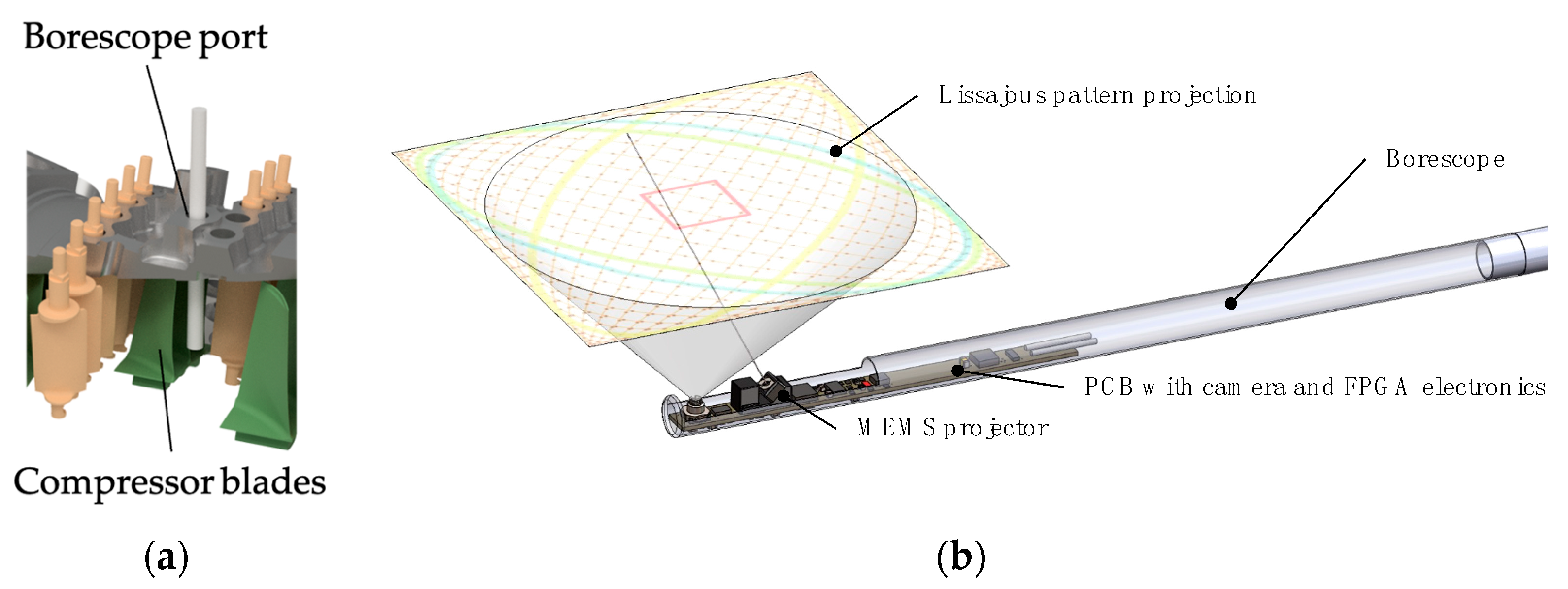
Borescope inspections (BIs) of aircraft engines impose specific requirements due to the limited dimensions of the inspection openings (borescope ports). These ports, which are sealed during engine operation, must be removed prior to inspection. Inside the engine, rigid or curved passages with small diameters guide the borescope to its final position. Different ports can impose varying hardware requirements, especially regarding diameter and flexibility, in order to adequately visualize critical components such as blades or vanes.
Within MRO (maintenance, repair, and overhaul) processes, the particular defect categories define the required lateral and depth accuracy of measurements. Achieving this accuracy calls for a micro-electromechanical systems (MEMS) mirror, whose size and performance parameters must be carefully matched to the camera and sensor elements in use. Selecting suitable MEMS mirror parameters requires an understanding of every component involved. For instance, the frequency of the mirror’s fast oscillation axis must be aligned with the desired resolution, the camera’s frame rates, and the number of samples taken per pixel. Moreover, the laser modulation frequency needs to be chosen in a way that accounts for potential thermal losses in the handle or the borescope head.
Also, the mirror design is mainly driven by the miniaturization of the structures. The resonant frequency is relatively low, and the mirror size is small, which requires more mass behind the mirror to enlarge the inertial tensor. Additionally, the laser spot diameter must be reduced to the projected area of the mirror in maximum angular deflection. To ensure a collimated laser beam, micromechanical positioning of the lenses and beam-shaping parts is required. The disturbances of the glass dome of the mirror must be considered when shaping the beam so that the disturbances are used as a part of the shaping.
To illustrate the requirements for a MEMS-based borescope, we focus on the widely used CFM56 turbofan engine from CFM International.
Figure 2 shows examples of defects, the dimensions of which must be measured. A CFM56-7B includes 21 borescope ports to access various engine sections. This work concentrates on the high-pressure compressor section, where four ports have diameters of 10.8 mm and three have diameters of 8.08 mm. Therefore, to pass through the smallest ports, the outer diameter of the MEMS-based borescope must remain under 8 mm. Since high measurement accuracy is desirable, both the data stream and the resulting thermal load at the borescope tip must be limited.
Initially, we analyzed resolution requirements in the high-pressure compressor (HPC) section of the engine for the requirements of the MEMS borescope prototype (see
Figure 3a). A CAD model of the section was analyzed to determine the measurement distances used in this port, which differ from 45–100 mm in stage 1 to 10–35 mm in stage 9. In practice, different borescopes or borescope head adapters are used for the various stages. Our prototype aims at a measurement distance of 35 mm. Thresholds for tolerated defect dimensions in this stage define the required lateral and depth resolution of the measurement borescope. For the measurement distance of 35 mm, we assume a lateral resolution of 80 μm and a depth resolution of 100 μm is required to determine whether thresholds are exceeded.
Additionally, the borescope should be at least 300 mm long because the probe must extend up to 110 mm inside the engine, and mounting is needed to fix the position during the measurement process. Other engine components, such as tubes or ducts near the ports, further restrict the space surrounding the borescope entry point.
Beyond these dimensional constraints, the device’s direction of view (DOV) and field of view (FOV) are crucial in covering the desired inspection area. A DOV of 90° typically enables scanning the blade surfaces by moving the borescope up and down within the port. Sensors with a 120° FOV are used to maximize the inspectable area, while the MEMS mirror offers a 60° FOV. This narrower mirror FOV represents a trade-off between wide coverage and mechanical robustness.
4. Conceptualization
For the concept introduced in this study, it is proposed that a MEMS scanner-based projection unit be incorporated into the borescope head. This unit would be complemented by the following three distinct measurement technologies:
LiDAR/phase shift distance measurement
Laser pattern triangulation
Stereoscopic vision with a flexible pattern
The integration of these diverse measurement principles allows for the mitigation of the limitations inherent to any single method by leveraging the strengths of the others. Moreover, the data obtained from each method can be verified against the others, enhancing reliability and enabling quality improvements through the fusion of multiple data sources.
Figure 3 illustrates the initial design iteration of the proposed borescope, featuring a Lissajous pattern projection at a 90° diagonal of view (DOV), a MEMS scanner, and a printed circuit board (PCB) equipped with a camera and electronics.
4.1. LiDAR/Phase Shift
LiDAR-based measurement systems can utilize either pulsed or continuous sine-modulated lasers. The pulsed method, also known as direct time of flight (ToF), involves measuring the time interval between the emission and detection of a laser pulse. This method requires time resolutions in the picosecond range because light travels approximately 300 µm within such a short duration. Due to the complexity of the electronics needed and the fact that there is only one rising edge per pixel, an alternative measurement technique is employed for depth information acquisition. Contrary to direct ToF, the phase measurement method, or indirect ToF, utilizes a continuous sine-modulated laser. It analyzes the phase changes in the modulated frequency to determine depth information. The chosen frequency represents a balance between resolution, frame rate, measurement depth, and the operating frequency of the MEMS mirror. These parameters must be carefully calibrated to match the specific application requirements.
The use of phase measurement introduces challenges related to the periodic nature of the signal. Consequently, the photodiode that detects the reflected laser signal is unable to discern depths exceeding the modulation wavelength. The photodiode signal represents a sub-sampling of the modulation frequency. The theory of sub-Nyquist sampling (SNS) facilitates signal reconstruction from a dataset that falls below the Nyquist–Shannon criterion. Provided that the sampling rate and frequency maintain a specific ratio (in this case, 4:5) and the phase remains fixed, the sine wave can be accurately measured. Once the sine wave is reconstructed, it is compared to the original modulation signal from the laser. The system’s Q/I filter uses this comparison to determine the phase shift between the two signals, which corresponds to twice the actual depth. Solving the following equation is necessary to align the measurement system’s parameters with the behavior of the MEMS mirror.
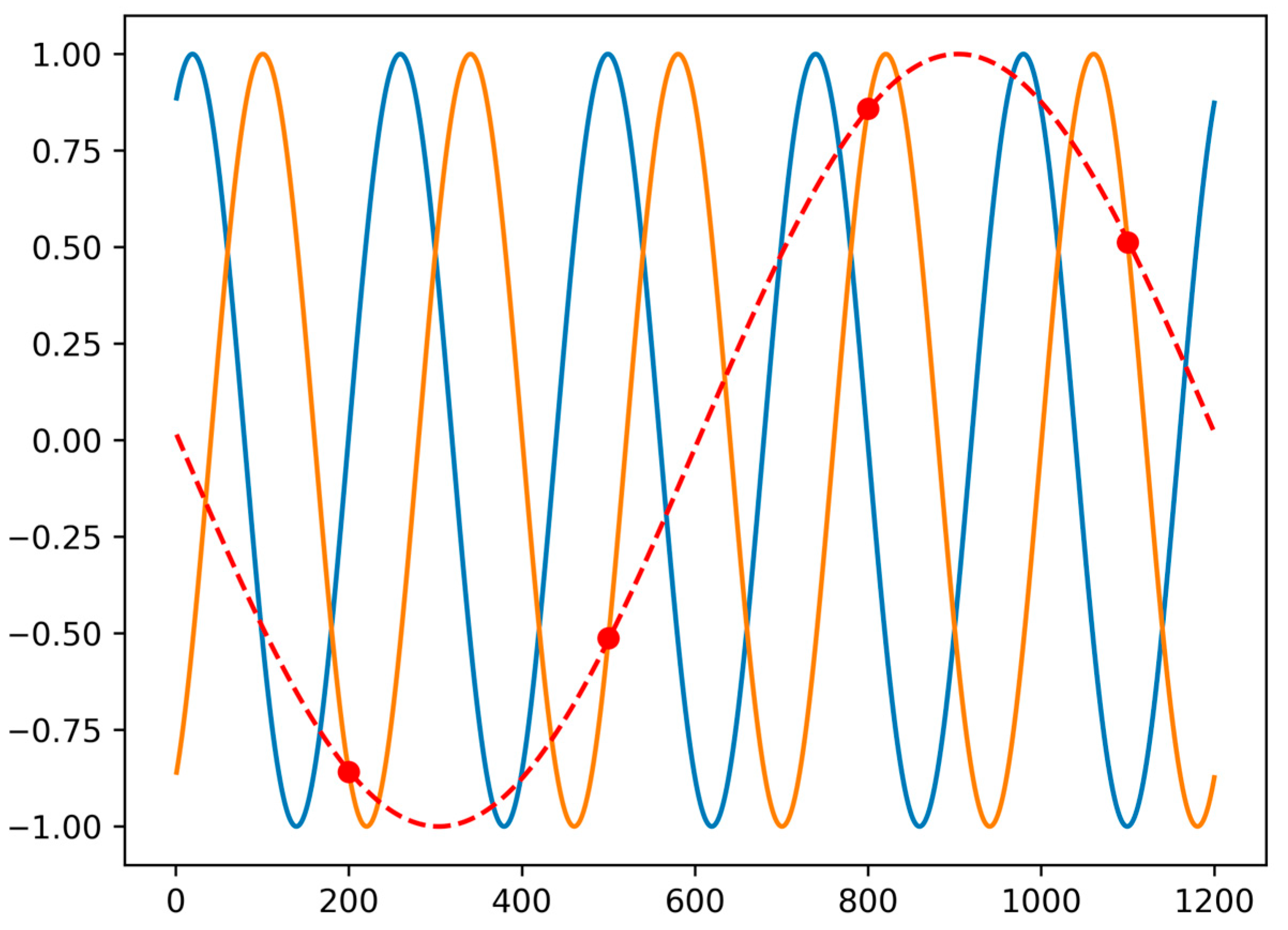
The SNS methodology relies on a fixed phase correlation between the sample rate and the modulation frequency. As long as four equidistant samples are taken within five periods, this constitutes a data block that represents the distance for one pixel. This signal can then be demodulated to extract both a phase offset and the signal intensity.
Figure 4 displays the emitted laser signal (blue), the reflected laser signal (orange), and the signal measured by the avalanche photodiode (APD) (red). The temporal shift between the blue and orange signals represents the travel time of the light from the laser diode to the APD. The APD is activated by the SNS ratio and captures the red data points. Utilizing these data, both the phase shift and the intensity are reconstructed, providing critical information for accurate distance measurement [
29].
4.2. Stereo and Pattern Triangulation
Triangulation-based measurements rely on the principle of triangulating corresponding points from two or more viewpoints using epipolar geometry, as illustrated in
Figure 5. In the measurement systems discussed here, epipolar geometry defines the geometric relationship between the two images (or between an image and a projection pattern), influenced by both intrinsic and extrinsic sensor parameters. Intrinsic parameters include variables that describe individual components, such as the focal length of the sensor lens. Extrinsic parameters, on the other hand, define the spatial relationship between the system components in terms of rotation and translation. This concept also applies to the pattern triangulation system, where one camera sensor is substituted with a projection unit. This substitution introduces unique intrinsic parameters, which must be determined during initial calibration. During measurement, corresponding points from both images (or between an image and a projected pattern) are triangulated. These points may be scene-inherent or artificially projected, unambiguous features identifiable through various algorithms and methods, such as blob detection for circular features. Consequently, the resolution of the resulting 3D data heavily depends on the number and type of feature points available for triangulation. This distinction underscores the primary difference between stereo vision triangulation and pattern triangulation.
Stereo vision triangulation can employ both scene-inherent and artificially projected features for feature extraction and subsequent triangulation. The inclusion of projected or artificial features enables triangulation in unstructured and featureless areas, where reliance solely on inherent features would be insufficient. In this setup, the projection unit’s role is limited to projecting detectable feature points across both camera images; thus, the quality of the projected pattern plays a secondary role in measurement accuracy.
Conversely, pattern triangulation exclusively utilizes artificial features, as the pattern observed by the camera sensor must be predefined to establish correspondences between the camera sensor and the projection unit. Since this method always requires a projected pattern, the presence of scene-inherent features is irrelevant. The effectiveness of this method is predominantly constrained by surfaces that may not reflect the pattern adequately, leading to fewer features that can be triangulated and increased measurement errors. In comparison to stereo vision, the projection unit in pattern triangulation must project the pattern more precisely, as the position of features within the pattern is critical for triangulation and directly impacts measurement accuracy.
5. Design of Head Assembly
To implement the LiDAR, stereo vision, and laser triangulation measurement principles, the sensor head must incorporate the requisite electronic components. For stereo vision, two RGB sensors, along with LEDs for white light illumination, are integrated, as shown in
Figure 6. The LiDAR setup includes an avalanche photodiode (APD) for detecting laser beams, which are emitted from a diode and directed by an optical system comprising lenses and a MEMS mirror. The equipment utilized for laser triangulation mirrors is also used for LiDAR and stereo vision measurements. Additionally, an Inertial Measurement Unit (IMU) is integrated to monitor the borescope head’s acceleration and rotation, as well as the temperature, to prevent overheating.
All components are mounted on printed circuit boards (PCBs), which facilitate inter-component communication and supply power. Control of the components is managed externally by a dedicated FPGA and microcontroller architecture to conserve the limited space available within the borescope head. As the MEMS mirror, the laser diode, and the associated optical system are central to all three measurement techniques, further details will be provided in the subsequent chapters.
5.1. MEMS Mirror
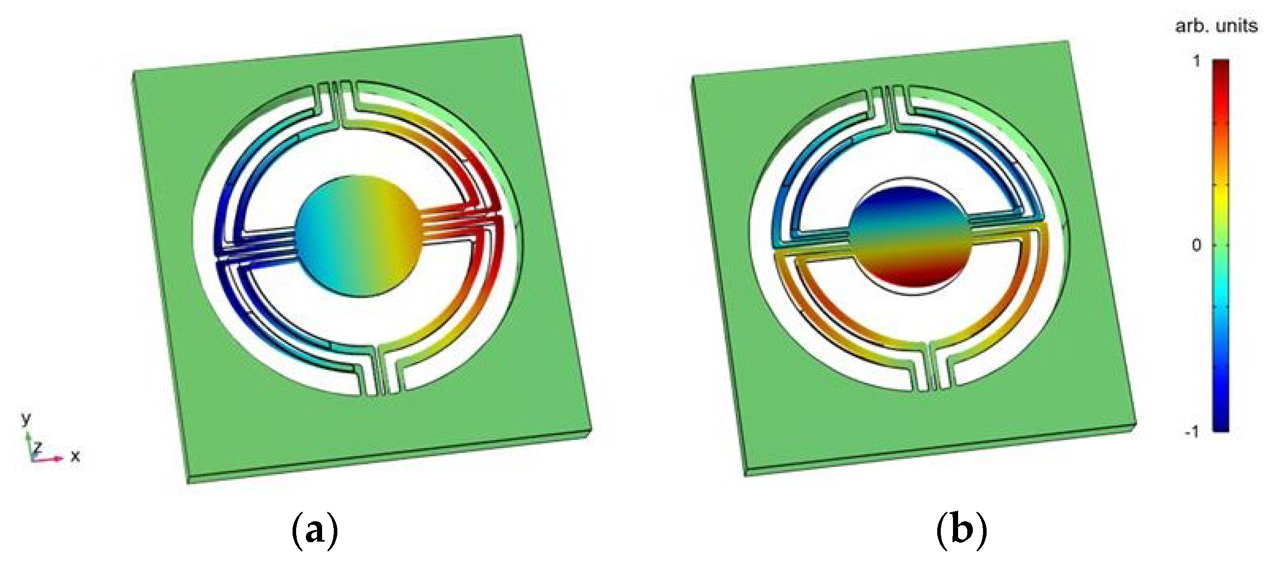
During the requirements analysis phase, Finite Element Method (FEM) simulations were conducted using Comsol Multiphysics to tailor the design to specific needs. Leveraging the high force output of piezoelectric materials, the MEMS mirrors are engineered to achieve substantial optical scanning angles up to 60°. A primary focus was placed on minimizing material stress to accommodate these large deflection angles. Concurrently, the specifications for resonant frequencies were established to range between 3–5 kHz, and a mirror plate diameter of 3 mm was determined, aligning with the laser parameters. The design incorporates two perpendicular scanning modes, as depicted in
Figure 7.
Furthermore, the MEMS mirror devices developed from these designs were fabricated on an 8-inch production line, utilizing a unique dome-shaped glass lid to maintain a vacuum environment and protect the device, as illustrated in
Figure 8. To facilitate the integration of the mirror into the overall system at a later stage, it is bonded to a PCB, and the electrical pads on the device are conductively connected to those on the PCB using wire bonding.
Initial experimental tests of the resonant MEMS mirrors, featuring two distinct designs, demonstrated a good correlation between the simulated and actual measured natural frequencies of the torsional modes. Operating the resonant mirrors with a sinusoidal voltage of ±30 V across both axes allowed for the projection of Lissajous figures, which achieved a high line density and comparatively low distortion, as depicted in
Figure 1.
5.2. Optical Setup
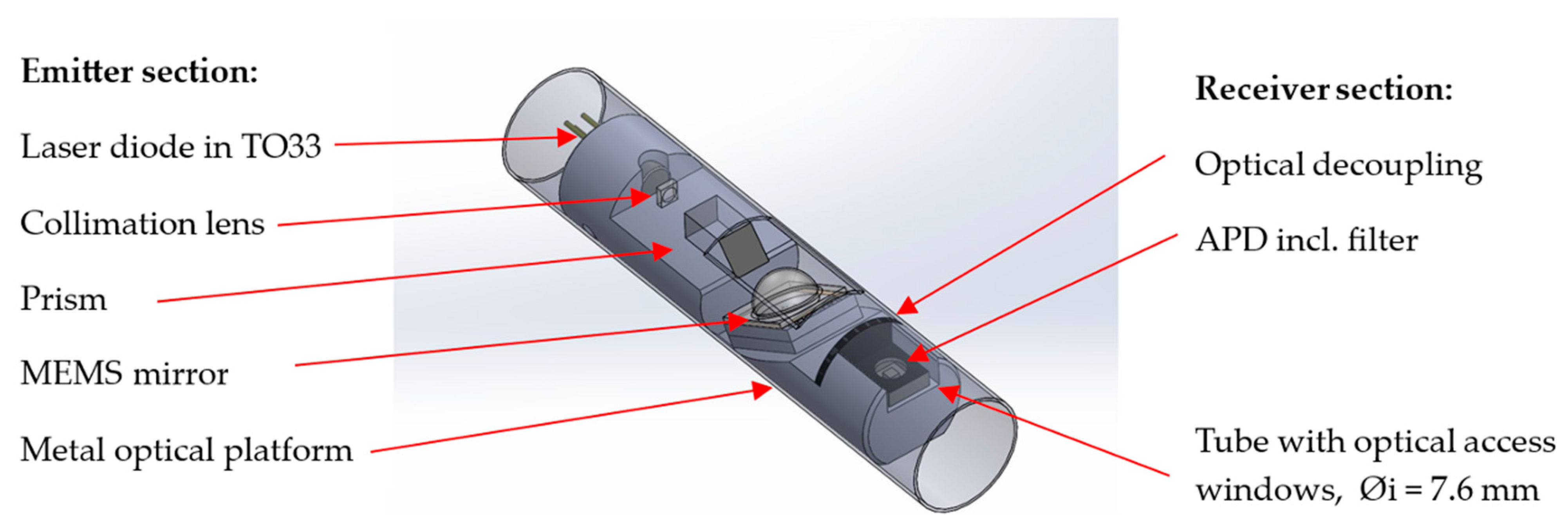
The design for the compact optics module, illustrated in
Figure 9, features a scanned laser source paired with an optically decoupled laser light receiver section. The development objective is to generate a 2D-scanned 100 µm green laser spot at an approximately 500 mm distance while maintaining the module within a 7.6 mm cylindrical outer diameter. A 15 mW CW green 520 nm laser diode housed in an exceptionally compact TO33 package has been chosen for the laser source. This diode is precisely positioned within a cylindrical bore to establish beam orientation, with provisions for precise back focus distance adjustments relative to a permanently mounted collimation lens. A single plane-convex lens is employed for collimation, replacing the traditional combination of Fast Axis Collimator (FAC) and Slow Axis Collimator (SAC) lenses. The collimated beam is then directed towards a MEMS mirror, which is mounted at a 30° angle. This arrangement is supported by a precision milled metal carrier, providing a stable optical platform. At the far end of this platform, the laser receiver is optically isolated by a barrier. Positioned immediately behind this barrier is an APD housed in a miniaturized ceramic package that also incorporates a 10 nm transmission filter for green light.
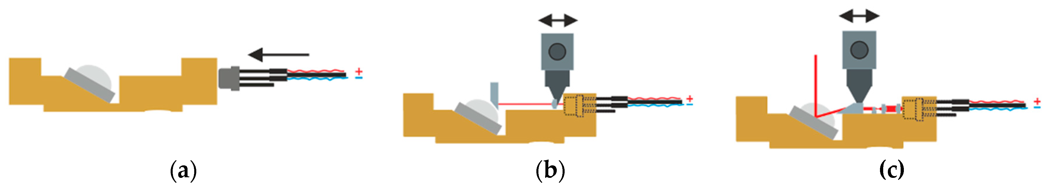
The assembly and focus setting procedures are executed using a FICONTEC precision pick-and-place machine equipped with an integrated laser controller and laser beam far field characterization capabilities. An assembly workflow was developed, as depicted in
Figure 10, that starts with an assembly of the MEMS mirror followed by oriented insertion of the laser diode housing. The collimation lens is placed on a UV-adhesive bed and pre-applied in the mounting position, which is determined by laser beam far field characterization.
Figure 11a illustrates the assembly process. The lens’s position is solidified by UV-LED illumination while it is held in place.
Subsequent steps involve the installation of any additional optional lenses and a prism. A final fine focus adjustment is made to counteract divergence caused by the glass dome, achieved by adjusting the laser diode’s position within the precision bore to achieve the smallest possible laser spot at a distance. This adjustment is continually monitored by a beam profiler, as shown in
Figure 11c. The diode’s position is secured with UV-adhesive and reinforced by an additional mechanical clamping mechanism.
Figure 11b displays the final alignment of the optical components.
5.3. Control Unit
The control unit processes the sense channels by analyzing their zero crossings and amplitudes. The mirror’s position is represented as a time-dependent function. Digitizing the angle allows the software to associate depth information with two angular measurements. Through a mathematical coordinate transformation, these data can be compiled into a 3D point cloud. Since there is a consistent delay in the mirror signals relative to the phase measurements, it is necessary to apply a phase shift correction to accurately correlate depth with the angular positions.
The position of the mirror can be determined in one of two ways: by timing interpolation between two zero crossings of the sinusoidal driver signal or by full sampling of the sense channels using analog-to-digital converters (ADCs). The electronic configuration for the MEMS driver and time-of-flight (ToF) device is shown in
Figure 12. The laser operation is contingent on both the phase shift and the current position of the mirror. Depending on the measurement system employed, the laser signal varies: the ToF measurement requires a sinusoidal laser signal, whereas the pattern triangulation system derives laser intensity from a stored image of the projected pattern, allowing for pixel-wise adjustments if the pattern causes sensor overexposure.
6. Data Analysis
As depicted in
Figure 11, the electronics embedded within the borescope head enable the implementation of the three distinct measurement principles outlined in the conceptualization phase. All integrated sub-sensor units are utilized to collect 3D data of the observed object. Furthermore, the cameras incorporated into the sensor head are leveraged to enhance the 3D data with color information, thus producing RGB-D data. Incorporating color into 3D measurements not only enriches the data with semantic information—such as identifying specific colors of materials or sediments—but also adds complexity to the system’s calibration. Consequently, RGB-D data fusion is selectively applied rather than being standard across all sensors. The subsequent sections will detail the individual sub-sensor units, their respective components within the borescope head, and the nature of the data they generate.
6.1. Stereo Camera Sensor
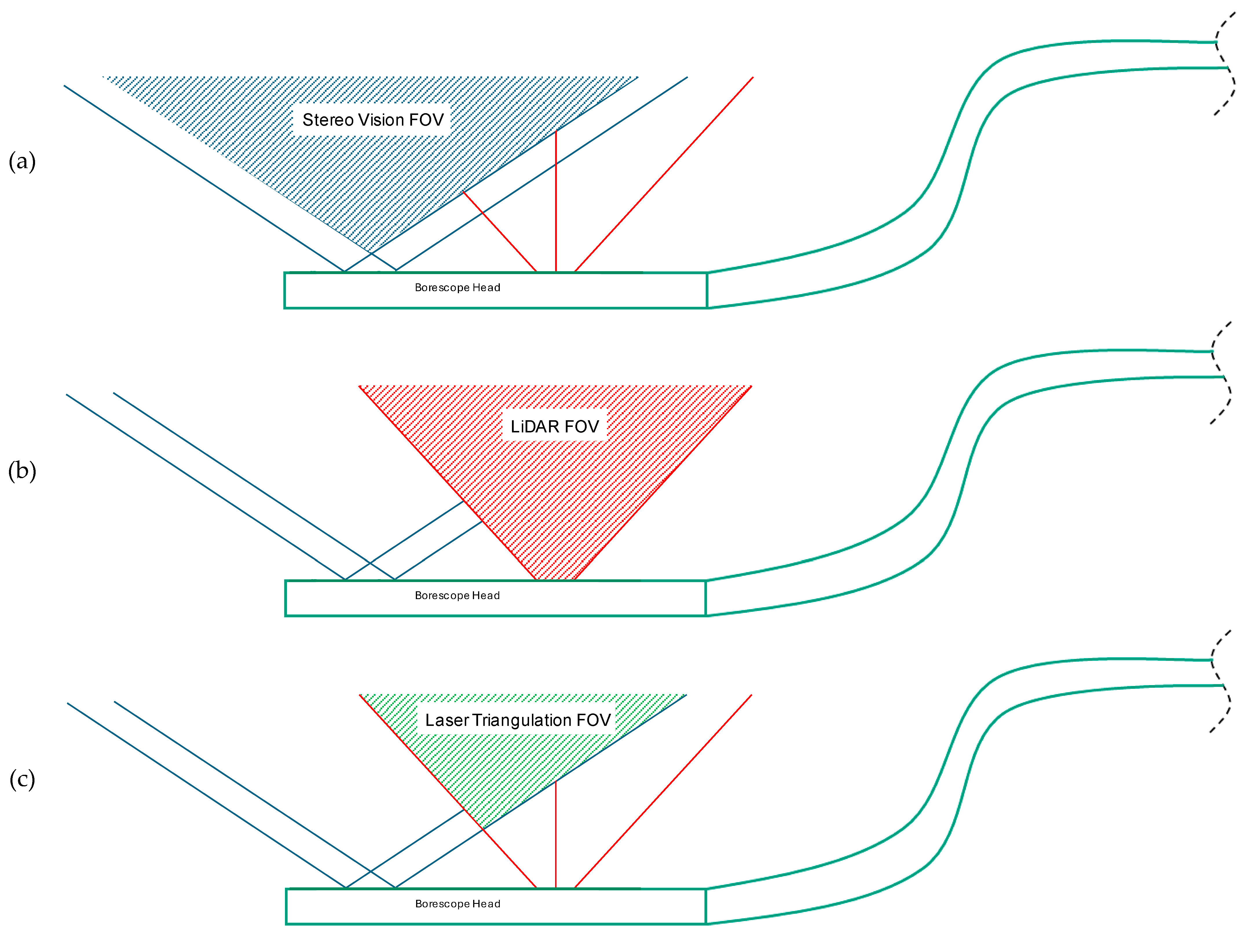
The stereo vision sensor captures 3D data by triangulating corresponding points within each camera’s field of view (FOV), which also delineates the measurement area (as illustrated in
Figure 13b). Within the borescope head, the stereo camera measurement employs both camera sensors along with LED lighting to illuminate the surfaces being observed. Consequently, it is imperative that both cameras are calibrated relative to one another. This calibration involves aligning both cameras’ intrinsics (such as the principal point) as well as the system’s extrinsics (the rotation and translation between the cameras). By establishing this calibration, corresponding 2D feature points identified in each image can be transformed into 3D coordinates.
The features targeted for triangulation are typically inherent to the scene, such as surface irregularities or color transitions. If the surface is predominantly uniform, leading to insufficient corresponding points for triangulation, the MEMS mirror and laser can be utilized as a projection system to create artificial features for triangulation. This approach can also enhance the accuracy of stereo vision measurements, particularly if a static scene is sequentially illuminated with different patterns and the measurements from each pattern are integrated subsequently. However, one limitation of employing the projection system is that it restricts the measurement system’s FOV, which is constrained by the FOV of both cameras as well as that of the projector.
6.2. LiDAR Sensor
The LiDAR sensor captures 3D data of the observed scene using the phase shift measurement technique. This sensor relies on a laser diode to emit a modulated laser beam, with the associated optics collimating the laser spot and the MEMS mirror directing the beam across the sensor’s field of view (FOV), as illustrated in
Figure 13c. On the receiving end, an avalanche photodiode (APD) detects the returning laser beam, which is then used to compute distances in subsequent processing steps. The distance data are merged with positional feedback from the MEMS mirror at the time of emission, culminating in the final 3D coordinates for each measurement point.
Initial calibration of the LiDAR sensor is crucial for capturing accurate 3D data. This calibration process involves determining the extrinsic parameters, such as the rotation and translation between the sender and receiver, along with other factors that may influence the laser beam’s path within the involved components.
To enhance the measurement capabilities, RGB data from one of the adjacent camera sensors can be integrated with the LiDAR data. While this fusion might slightly limit the FOV, it provides enriched RGB-D data. For successful data fusion, the camera sensor must be calibrated in relation to the LiDAR sensor unit, ensuring that the translation and rotation relative to the LiDAR sensor’s coordinate system origin are accurately known. Additionally, determining the camera’s intrinsics is necessary to correct for image distortion and other optical effects.
6.3. Laser Triangulation Sensor
Within the borescope sensor head, the laser triangulation sensor employs the MEMS mirror, a laser diode with its optics, and one camera sensor to generate 3D data. This process involves projecting a known pattern using the MEMS system, which is then captured by the camera sensor. Accurate triangulation of the individual feature points of the projected pattern into 3D points is contingent upon the calibration between the camera sensor and the MEMS system. The precision of the projection and the ability to project without distortion are critical for collecting reliable 3D data.
The field of view (FOV) of the laser triangulation sensor, depicted in
Figure 13c, is defined by the camera sensor and the MEMS mirror. Additionally, the 3D data can be enriched with RGB information from another camera sensor, necessitating further calibration to accurately map colors.
The resolution of the measurements, determined by the number of features triangulated—and thus the number of measurement points—depends significantly on the projected pattern. The design and intricacy of this pattern can be tailored to adjust the measurement resolution. This feature allows for selectively enhanced resolution in areas of greater interest within the sensor’s FOV.
7. Discussion
As detailed previously, the concept for a MEMS-based measuring borescope aims to integrate three distinct measurement principles into a single borescope head for inspection tasks. Since the implementation description is conceptual and hardware development is ongoing, this discussion addresses challenges and future tasks.
A primary area of development concerns thermal management due to heat generated by the electrical components, particularly the laser module and its modulation. To address this, one strategy could be to use a system with limited laser output power and a smaller laser diode within the borescope head. However, this might necessitate heat pipes or active gas cooling, potentially introducing other undesirable effects. Research is currently exploring the use of TO-housed diodes as another potential approach. Alternately, in the next development step, thermal issues may be solved by placing the laser diode and driver in the borescope handle. Fiber optics transmission of the modulated laser brings the following two improvements. It places the heat source in the handle, where the heat can be transferred to the operator’s hand. Additionally, with a fiber-coupled lens, the beam shaping is drastically simplified.
The LEDs in the distal end will be pulsed. This means that frames that detect dynamic structured light and are used for 3D point cloud calculation will not be illuminated by white light LED. The timing of the sensor is synchronized to reduce the LED up-time to the sensor’s exposure time. This means that during the image transmission time, the LED is also shut off. If the distal end still overheats in the future prototype, unless the mentioned steps to reduce heat emissions are taken, the next step would be to implement a thermal resistor to reduce the LED’s up-time or current.
Another challenge is designing the handle to accommodate the described electronics, especially the MEMS mirror and power electronics. Furthermore, the optical separation between the laser module, camera sensors, and the APD is essential to prevent measurement inaccuracies due to scattered light; the housing of the head and its glass surfaces for laser emission and reception should also be considered.
The borescope head’s size and structural and optical demands make manufacturing and assembling it particularly challenging, marking another area of ongoing research.
Post-assembly testing of the firmware for various devices and drivers is required. Valid measurement data necessitates calibrating the different sensor types. While established methods exist for systems like the stereo camera, new techniques need to be developed for integrating projected patterns into the measurement process, such as laser triangulation, and calibrating the camera sensor to the MEMS mirror. The same applies to the LiDAR sensor, where calibration between the MEMS mirror as the emitter and the APD as the receiver is expected to be challenging due to the small scale of the sensors.
System-wide calibration, or inter-sensor calibration, is also necessary for data fusion and seamless transitions between data from different sensor types.
The MEMS mirror’s capability to project structured light can enhance measurement outcomes, particularly in areas lacking features necessary for traditional stereo triangulation algorithms. Dynamic pattern projection aids in detailed edge recognition and ensures comprehensive data collection by adapting the pattern to match surface triangulations.
Additionally, with the MEMS mirror, another measurement mode is feasible using time or phase shift analysis between the sent and detected signals. This technique is less affected by surface reflectivity and can utilize a larger workspace since the maximum distance for the time-of-flight measurement system depends on the modulation wavelength rather than intensity across the sensor surface. However, the system’s sensitivity to stray light due to the photodiode’s broad coverage requires further exploration.
Ultimately, practical validation of the conceptual design is pending. The initial application will be in borescope inspections of aircraft engines, providing a real-world environment to test the three measurement methods. The first validation cycle might use a larger measurement head to focus on method validation without the complicating factors of miniaturization, such as heat management. Subsequent cycles will employ the sensor head at its final size to also consider miniaturization effects.
8. Conclusions
The sensor system’s development process began with a detailed analysis and definition of the borescope inspection (BI) requirements. The capabilities of the MEMS-based scanner, the geometric constraints, and the integration of different sensor systems were evaluated concurrently to ensure alignment between requirements and capabilities.
This study highlights the significant potential of dynamic structured light, which projects patterns onto unstructured surfaces to enable 3D reconstruction. Adjusting the pattern in various directions enhances edge detection in the images and reduces measurement errors. Additionally, phase-modulated LiDAR systems offer high-resolution depth measurement, expanding the measurement area to support the stereo point cloud or to operate over longer distances. The phase measurement approach, a variant of the time-of-flight principle, achieves higher accuracy with less stringent time-resolution requirements. Given the intended use of the borescope in enclosed spaces, laser intensity need not conform to Class 1 safety standards, provided the system is deactivated when removed from these environments.
To facilitate integration, the borescope head combines a stereo measurement sensor system with white light illumination and a MEMS mirror for either pattern projection or LiDAR. This arrangement is versatile and suitable for various use cases as it accommodates a wide range of working distances and enhances data quality through the synergy of multiple measurement principles. For manufacturing, the stereo sensor and MEMS sections are produced separately but assembled with precision to maintain a consistent and reproducible position, utilizing cones and a lockable mounting system. This modular design allows for separate repairs of the sections after disassembly.
Two concepts for integrating the laser into the system were investigated, both dealing with the complexity of optics needed to reduce the beam diameter to below 150 µm. The first option involves housing the laser and its driver within the borescope head, whereas the second utilizes fiber optics to mitigate heating at the distal end by positioning these components in the handle. However, using fiber optics introduces the risk of phase displacement in the sinusoidal signal.
For the calibration of the sensor system, the angular mirror positions must be transformed into Cartesian coordinates. The mathematical model for this and the correlated calibration method need to be developed because this is the solution for correlating RGB, photodiode, and MEMS position data. The localization of the laser point on a surface needs to be acquired and transformed into a dataset for Cartesian coordinate determination. Even the laser intensity needs to be corrected because the illumination time of the edges is higher, so the speed of the mirror is minimal at the inflection points of the axes. To ensure constant sensor exposure, the laser intensity needs to be corrected. This capability can be enhanced to trim the pixel-wise exposure to the surface’s reflectivity.
Communication between the head, handle, and a connection box (preceding the computer) utilizes a proprietary protocol, managing data transfer for sensor parameters, MEMS status, photodiode data, and RGB images.
The conceptual framework has demonstrated its capabilities, and the performance of each component has been validated in a large-scale prototype to identify any system shortcomings. Encouraged by positive outcomes, the miniaturization to a diameter of 8 mm is a pivotal focus, with further advancements expected to be detailed in subsequent research and publications. The miniaturization poses several challenges to overcome before building the prototype, such as heat dissipation and miniaturization of the MEMS mirror and optical unit. Additionally, the PCBs used for controlling and powering the components must be reworked due to size limitations. This may result in a redistribution of the components between the borescope head and handle, as compared to the large-scale prototype. Further challenges are expected during miniaturization that are not yet apparent.
The authors’ future work includes validating the described concept by building a prototype that enables the implementation of all three measurement principles. Within the framework of a validation environment modeled on the aircraft turbine, an extensive measurement series will be implemented using the various measurement principles so that each principle can be tested for suitability and successful implementation.
Furthermore, long-term tests with the prototype sensor system are planned in order to analyze the stability of the electronic components in real operation. This also includes testing the sensors under various environmental conditions, including vibrations, temperature fluctuations, and humidity. The results will then be compiled in an appropriate manner, and recommendations for future developments will be made.


 ,
, 