Article

Aerodynamic Analysis of a Hexacopter with an Inner Tilted-Rotor Configuration During Hovering

School of Mechanical Engineering and Automation, Fuzhou University, Fuzhou 350116, China
*
Author to whom correspondence should be addressed.
Aerospace 2025, 12(4), 317; https://doi.org/10.3390/aerospace12040317
Submission received: 26 February 2025 / Revised: 1 April 2025 / Accepted: 1 April 2025 / Published: 8 April 2025
(This article belongs to the Special Issue Aircraft Design and System Optimization)

Abstract

:
The present work is aimed at investigating the arrangement design of an inner tilted-rotor hexacopter to optimize aerodynamic performance with different rotor spacing ratios (s/D) and dihedral angles (β). Both experiments and numerical simulations were applied for different rotor arrangements, and the better rotor agreement was related to both higher thrust and lower power consumption. The results show that hovering efficiency is mainly affected by rotor spacing ratios and dihedral angles. Appropriate rotor spacing with moderate rotor interference from the blade tip vortices, as well as downwash flow, reduce vortex distortion and fragmentation. The results show that a hexacopter with inner tilted-rotors obtains a larger thrust and smaller power with a high factor of merit (FM) at s/D = 1.6 and β = 40°, and this is considered to be the optimal arrangement for a hexacopter with excellent aerodynamic characteristics.

1. Introduction

With the rapid development of the general aviation market, the application of multirotor unmanned aerial hexacopters (UAVs) is becoming increasingly widespread [1]. UAVs have unique capabilities, such as vertical takeoff and landing and stable hovering, which enable them to provide cost-effective solutions in the military, industrial, and civil sectors by carrying a variety of sensors on board [2,3,4,5]. The propellers of conventional multirotor UAVs are typically positioned within the same plane, and this configuration has been widely adopted due to its simple and compact structural design. However, conventional multirotor UAVs have an underactuated structure due to the coupling between horizontal translation and rotational dynamics. Compared with conventional multirotor UAVs, tilted multirotor UAVs are prominent in current research due to their overactuated characteristics [6,7,8]. Hexacopters with tilted-rotor configurations can perform transverse roll and yaw motions under horizontal states and thus possess higher flight accuracy, safety, and stability. Various designs of tilted multirotor UAVs have been proposed in the related literature [9]. These hexacopters are characterized by the fact that their rotors are no longer parallel to each other. The rotors can be tilted around a radial axis, called the tangential tilt angle (α), or around an axis perpendicular to the radial axis, called the dihedral angle (β).
Voyles et al. [10,11], proposed the concept of a hexacopter equipped with tilted-rotor configurations and demonstrated that tilted rotors can effectively suppress lateral disturbances [12]. Rajappa et al. proved that suitable α and β angles can minimize the total thrust required for a full-attitude UAV for a given trajectory, thus ensuring its controllability [13]. Giljarhus et al. demonstrated that a simplified Blade Element Momentum Theory (BEMT) model can handle the simulations for coaxial rotors with varying pitch angles [14]. In Jiang’s study, the physical interaction between the tilt angle and dihedral angle was determined using a multi-objective optimization approach [15,16]. Michieletto’s study showed that a non-zero β-angle provides the hexacopter with robustness against rotor failures. At the same time, the dihedral angle does not affect the yaw torque by effectively reducing the overall torque [17]. However, most of these studies are focused on the control strategies without any field tests, especially for the aerodynamic performance of inner tilted-rotor hexacopters. For a hovering state, different combinations of rotor spacings and dihedral angles lead to changes in aerodynamic interactions between adjacent rotors, resulting in thrust variation and, thereby, loading fluctuations that directly affect the stability and control behavior of the hexacopter. Evaluating the aerodynamic characteristics of an inner tilted-rotor hexacopter with different configurations is a challenging task since there are a number of variables involved, not to mention complex interactions.
Recent studies on aerodynamic performance have focused on wind tunnel tests and numerical simulations. Deng et al. studied the aerodynamic performance of rotor blades in hover and forward flight using wind tunnel tests. They found that the lift offset in forward flight can significantly improve the aerodynamic performance of rotor blades [18]. Lei et al. proposed an overlapping octo-rotor UAV with optimal rotor spacing to improve hovering efficiency at 1.8D [19]. Zhang et al. conducted a series of tests on the ground effect with numerical simulations on a hexacopter propeller with a high-fidelity CFD-based study integrated with the overset mesh method [20]. Rostami carried out an aeroelastic analysis on elastic wings and verified it by comparing it with wind tunnel test data. The results showed that the aerodynamic characteristics of the propeller affect the longitudinal movement by about 20% and the lateral movement by about 5% [21]. Vargas et al. discussed the suitable methodology for the aerodynamic analysis of propellers by comparing BEMT and unsteady CFD simulation models for a small low-Reynolds propeller [22]. Aziz et al. used the Virtual Blade Method (VBM) to obtain the aerodynamic characteristics of co-axial rotors and hybrid octo-rotor configurations in hover and forward flight states. It was found that the increasing vertical spacing of the co-axial octocopter reduces noise values [23]. Ventura et al. analyzed the aerodynamic disturbances of a multi-copter in hovering and provided a theoretical basis for the optimal design of multirotor UAVs [24].
This research aims to explore the optimal rotor arrangement for an inner tilted-rotor hexacopter during hovering and seeks better aerodynamic performance by analyzing the effects of rotor spacings and dihedral angles. The main contributions are as follows: (1) This paper focuses on the combined effects of different combinations of the rotor spacing ratio (s/D) and the dihedral angle (β) on the aerodynamic performance of an inner tilted-rotor hexacopter and tries to optimize the aerodynamic performance of a novel UAV. (2) Both experiments and numerical simulations are performed to investigate the aerodynamic characteristics of the inner tilted-rotor hexacopter during hovering and will provide more data for future field flight tests.

2. Materials and Methods

2.1. Geometry Models

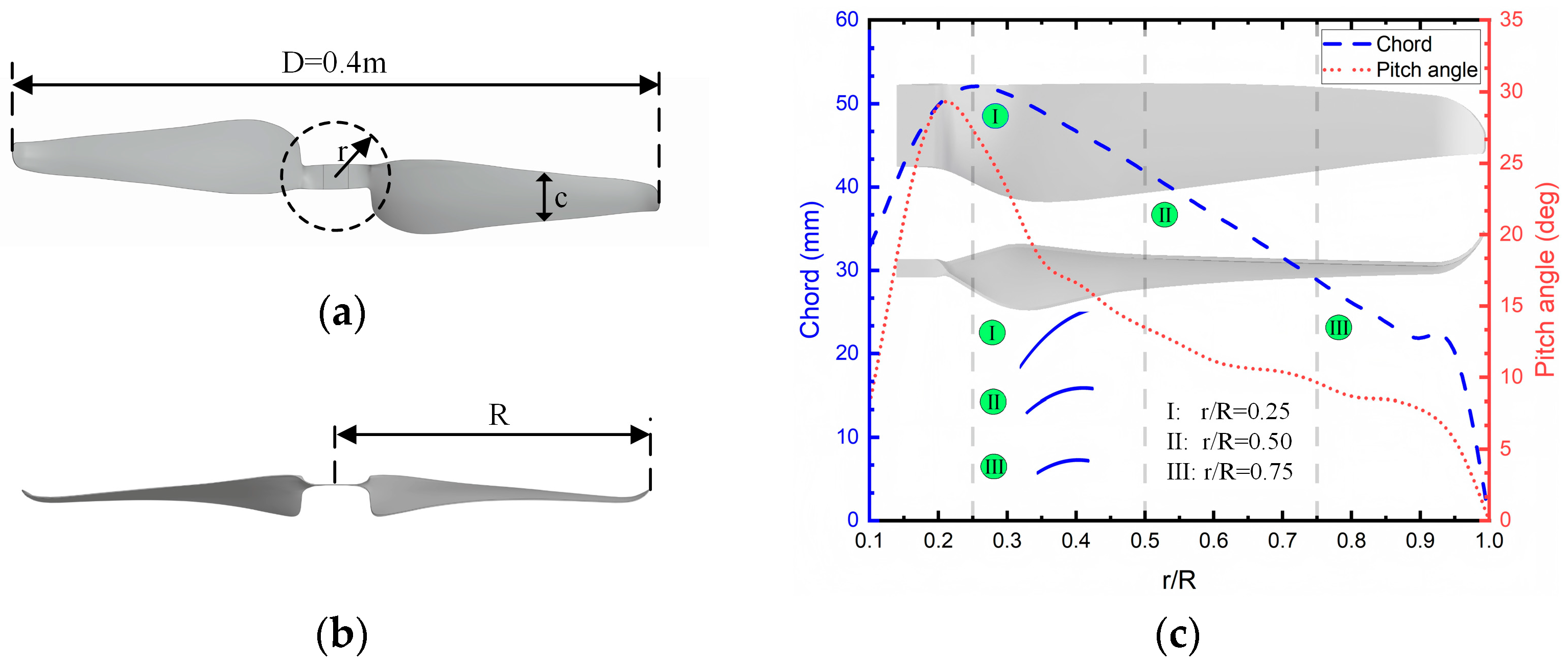
2.1.1. Propeller Geometry

The propeller utilized in this study is made of carbon fiber. The 3D geometry of the propeller is provided in Figure 1. Moreover, the chord and pitch distribution are shown in Figure 1c, where r is the length along the radius direction, and R is the rotor radius. Additional parameters are listed in Table 1.
The Reynolds number on the rotor tip is defined as follows:
R e t i p = ρ v b μ
where ρ is the air density, v is the rotor-tip speed, b is the average chord length of the rotor, and μ is the dynamic viscosity of the air.
The propeller speeds range from 1500 to 2300 RPM, with Reynolds numbers ranging from 0.75 × 10⁵ to 1.25 × 10⁵; thus, the tip Mach number is 0.1–0.15. For this study, the classical speed of 2200 RPM of this propeller was taken as the experimental condition. The maximum Reynolds number for a propeller tip in these tests was about 1.08 × 10⁵. A previous study [25] showed that the aerodynamic performance of the hexacopter is independent of the Reynolds number when it falls between (0.46–2.2) × 105. Thus, other Reynolds numbers were not considered in this research.

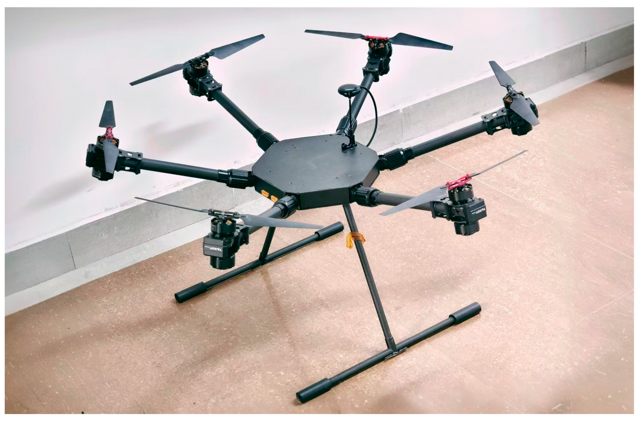
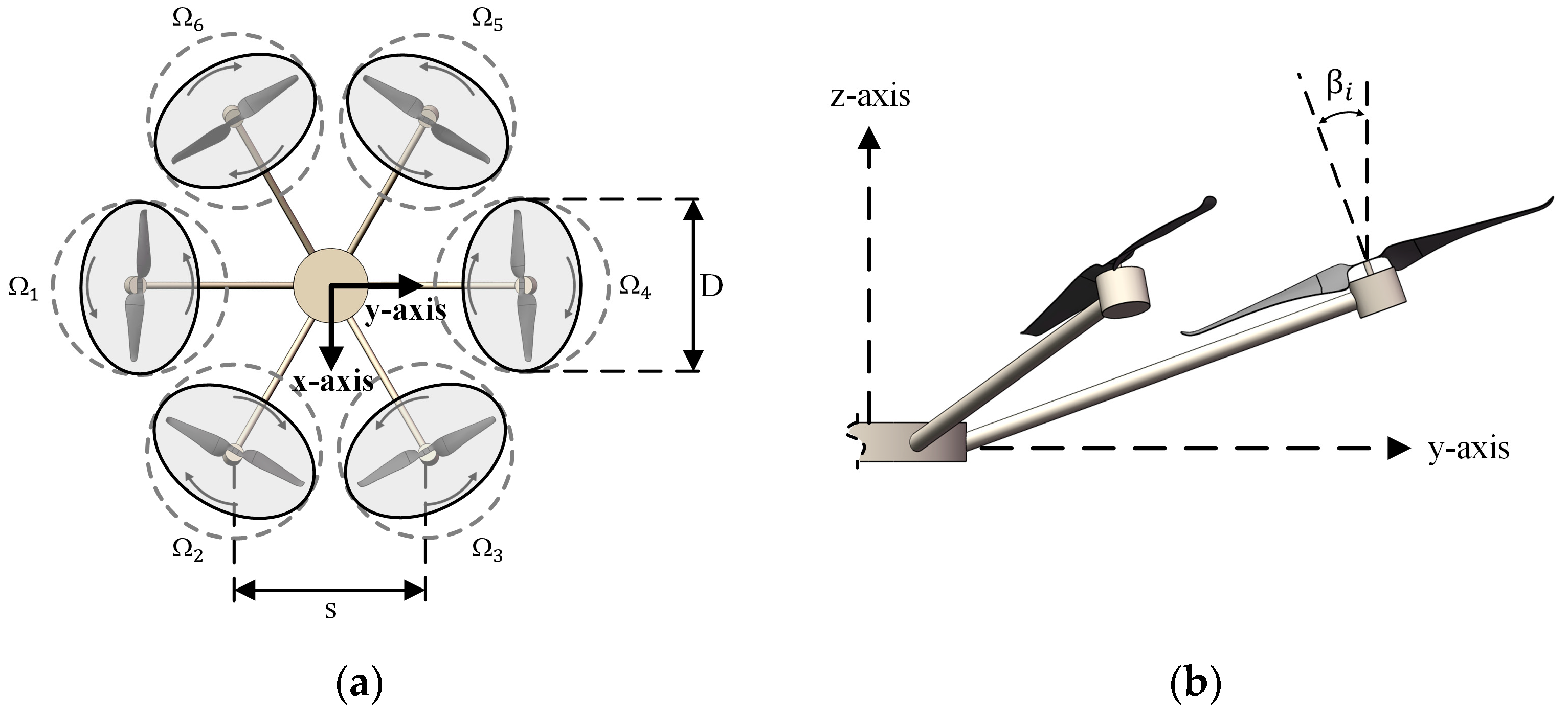
2.1.2. The Structure of the Inner Tilted Hexacopter

The prototype of the inner tilted-rotor hexacopter is shown in Figure 2, and the structure detail is given in Figure 3, where D is the diameter of the rotor, s is the spacing between adjacent rotors, Ω is the rotational speed, and β is the dihedral angle.
To study the influence of rotor spacing on the aerodynamic performance of hexacopters, the rotor spacing ratio is defined as follows:
i = s/D
Figure 4 shows the aerodynamic interference in an inner tilted-rotor hexacopter. Clearly, the aerodynamic interference between adjacent rotors varies with rotor spacings and dihedral angles. Both variables increase the complexity of the aerodynamic interference of the hexacopter since the inflow interacts with each other.

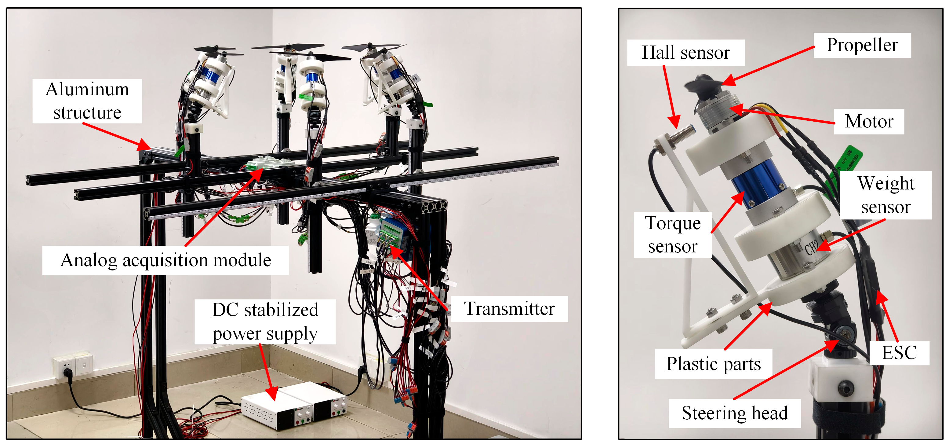
2.2. Experimental Setup

Figure 5 shows the experimental setup to measure the hovering performance of the inner tilted-rotor hexacopter. The test bench mainly consisted of a propeller unit, a data acquisition system, an electric power system, and a test frame. There are six groups of propeller units, including propellers, electronic speed controls (ESCs), and motors. The data acquisition system included thrust sensors, torque sensors, tachometer. The frame of the test bench is made of aluminum alloy. Different rotor spacings and dihedral angles of the hexacopter could be adjusted by changing the spacing between the support rods and the angle of the steering heads. To avoid airflow interference caused by ground effect as well as wall effect, the distance between the propeller and the ground was about 5D, and the distance between the test bench and the wall of the site was not less than 7D.
The propeller unit was powered by the power supply and the speed was set at 2200 PRM, controlled by a hall sensor. The measurement error was within 3%. Table 2 presents the parameters of the various instruments in the test bench. By changing the dimensionless distance (s/D) and dihedral angle (β), the thrust, current, and power consumption were recorded in tests. The operating conditions are summarized in Table 3. For each configuration, three replicate trials were conducted, with 60 s of data collected per trial.
The main error came from the sensors, which could be calibrated by repeated measurements. The measurement results show that the thrust difference of the six load cells at β = 0° is less than 0.1 N, and the deviation of the torque sensor is less than 0.002 N·m. When β = 50°, the errors are less than 0.15 N and 0.005 N·m, respectively. The errors between the sensors at different positions are within the acceptable range, which meets the experimental requirements.

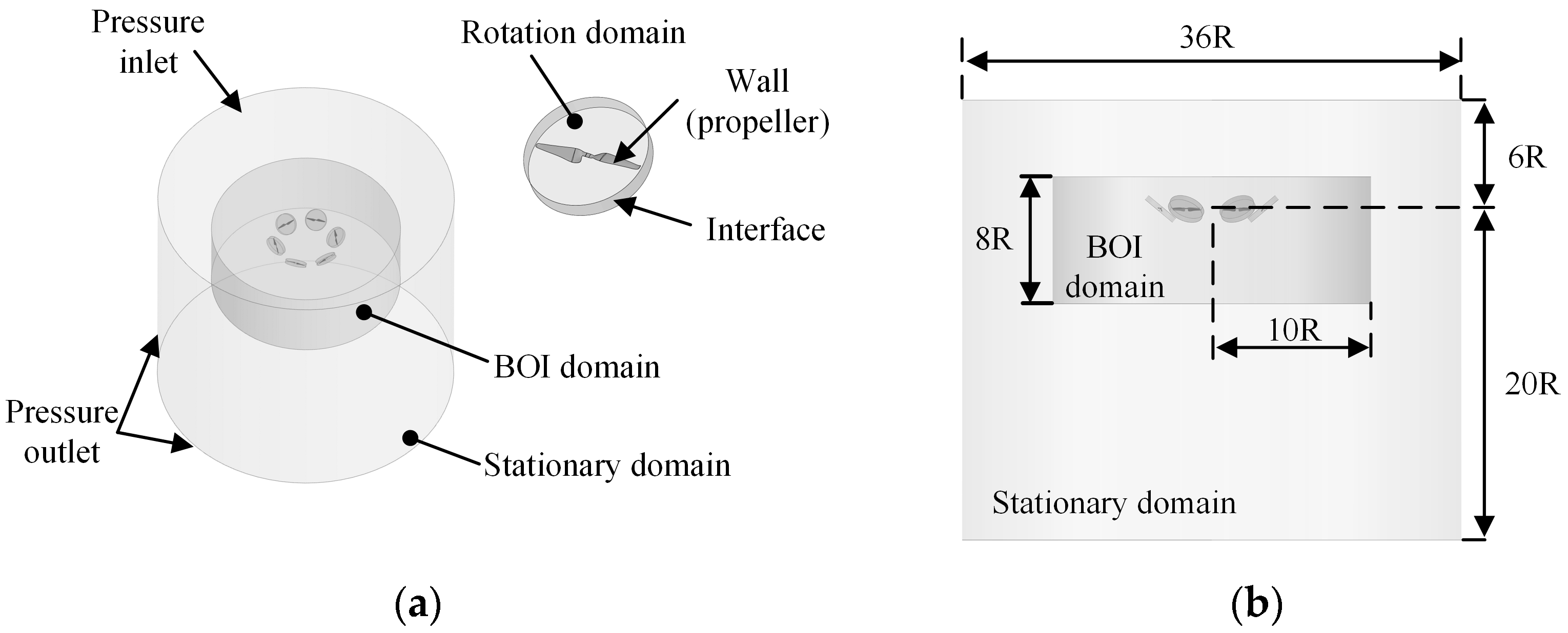
2.3. Numerical Simulations

2.3.1. CFD Methodology

ANSYS-Fluent (2021 R1) was adopted to simulate the flow field of the hexacopter. The Reynolds time-averaged Navier–Stokes (N-S) equations and the shear-stress transport (SST) k-omega turbulence model were applied in all simulations [26,27]. Also, the coupled scheme was selected as the pressure-based coupling algorithm with a second-order scheme. To obtain the details of the flow field around the rotor tip, the Moving Reference Frames (MRFs) and Sliding Mesh Model (SMM) methods [22,28,29] were used in the simulations. This paper first performed the MRF method to obtain the stable initial value of the flow field, then used the Text-based User Interface (TUI) command to modify the solution mode for a transient state, and finally created the interfaces with the SMM method to complete the final calculation.
Figure 6 shows the computational domain and boundary conditions. The domain contains one stationary domain and six rotation domains, with each propeller corresponding to one rotation domain. To analyze the aerodynamic characteristics of the hexacopter with different rotor spacing and dihedral angle configurations more clearly, the components such as the fuselage and the arms were excluded from the analyses of the present simulation. In addition, to capture the details of the vortices generated by the propellers, a Body of Influence (BOI) domain was generated when the mesh was refined.

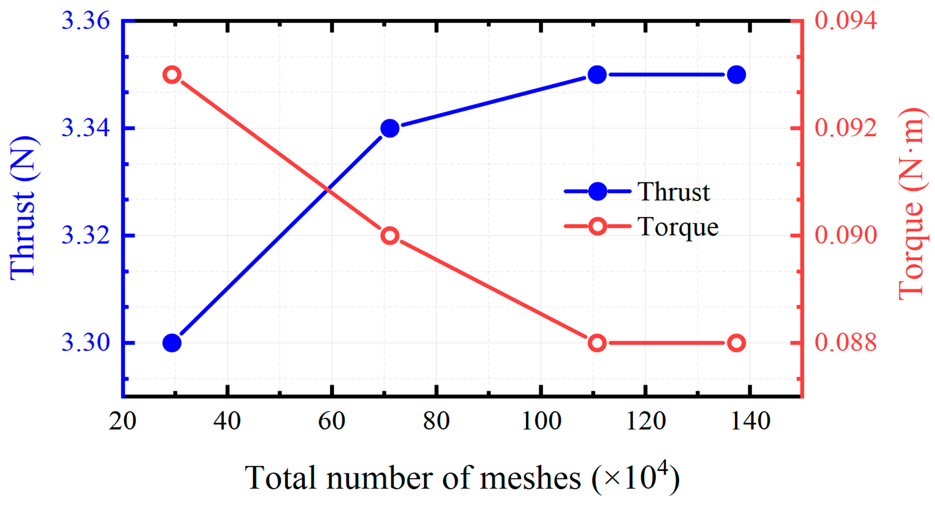
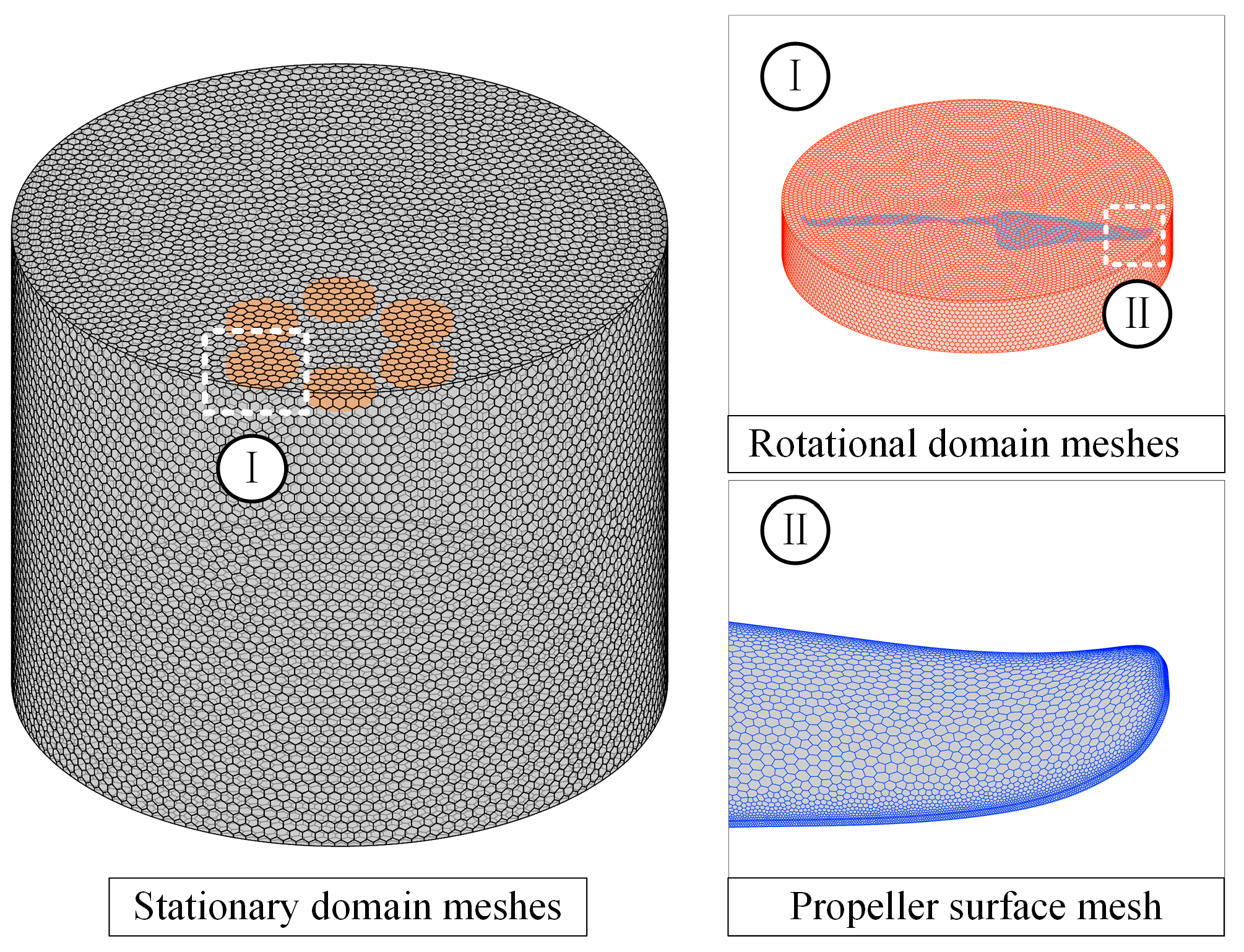
2.3.2. Mesh Sensitivity Study

To minimize the influence of the mesh size on computational accuracy and to improve the reliability of the simulation results, the mesh sensitivity of the isolated propeller as well as the hexacopter was investigated. Table 4 shows the number of meshes for four configurations and their simulation results. Figure 7 shows the variation of thrust and torque with different mesh numbers. It can be seen that the thrust increases with the number of meshes, whereas the torque decreases with it. In addition, the average y+ value for Mesh 3 is about 32, as recommended in [25], resulting in higher stability, and it is proven to be sufficient for computational accuracy.
Figure 8 shows the mesh distribution. Three sets of meshes were proposed on the hexacopter flow field with a fixed value of 2 mm. Table 5 shows the cases of the number of meshes for the three configurations and their simulation results. It can be seen that the gap between the values of the thrust gradually decreases with the increase in the number of meshes.

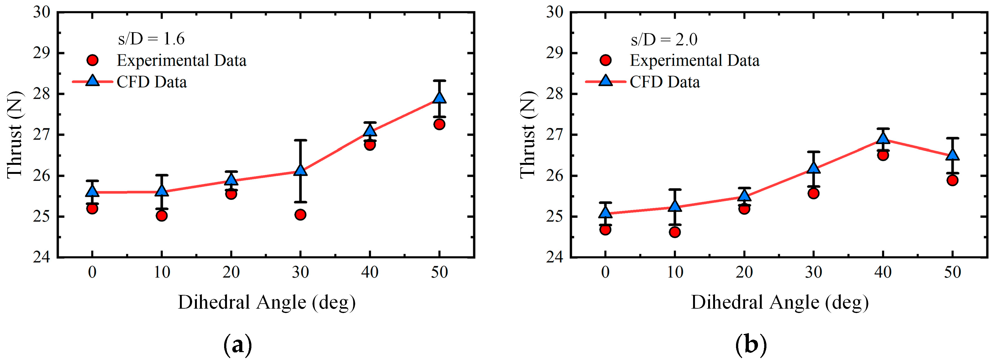
2.4. Data Validation

The validation of the CFD simulation calculations was combined with the experimental data. Figure 9 shows the comparison of the thrust. It can be seen that these are generally in good agreement, with errors of less than 10%.

3. Results and Discussion

To evaluate the aerodynamic performance of the hexacopter, the following variable was used for analysis. Propeller power is calculated by the following equation:
P = 2 π n Q
where Q is the torque, and n is the rotational speed measured in revolutions per second.
The thrust and power coefficients were then calculated by the following equations:
C T = T ρ n 2 D 4
C P = P ρ n 3 D 5
where T is the thrust generated by the propeller.
The efficiency was in the form of the hover figure of merit or the FM. The FM is calculated by the following equation:
F M = C T 3 2 ( 2 C P ) = T 3 2 Q Ω 2 ρ A
where A is the rotor disc area.

3.1. Experimental Results

For a traditional multirotor UAV, β = 0°, and this can be used as a comparison to investigate the aerodynamic performance of the inner tilted-rotor hexacopter with a varied rotor spacing ratio (s/D) and dihedral angle (β).
Figure 10 shows the thrust variation of the hexacopter. For a fixed rotor speed, the thrust in the conventional hexacopter shows a tendency to increase and then decrease with the increase in rotor spacings and reaches a maximum value near s/D = 1.6. For a smaller spacing, strong aerodynamic interference will lead to the loss of thrust. Furthermore, the aerodynamic interference is weakened with a higher spacing ratio, and the thrust decreases and tends to be stabilized, which indicates that the appropriate aerodynamic interference improves the performance of the novel hexacopter. Also, the thrust generated by the novel hexacopter is much improved when s/D = 1.6 and β = 50°, reaching a maximum value of 27.25 N, which is 8.15% higher and has a similar “face-to-face” layout [30]. Similarly, the hexacopter thrust reaches 26.75 N at s/D = 1.6 and β = 40°, which is 6.17% higher than that of the conventional hexacopter. It is also worth noting that the thrust reaches its minimum when the rotor spacings are small and the dihedral angle is large, which is due to the drastic aerodynamic disturbances caused by the smaller rotor spacings and the larger dihedral angles.
Figure 11 shows the power generated by the hexacopter with different rotor spacings and dihedral angles. The power consumption of the hexacopter in a hovering state is critical to the thrust generation and duration time. Higher power consumption leads to shorter hovering times for a given battery capacity, and in addition, prolonged high-power hovering may lead to overheating of the motors and batteries. Therefore, there is a tradeoff between the thrust and hovering times.
For the tilted rotor arrangement, there is a general increment. It reaches 7.22% at β = 50° with large rotor spacings resulting in significant energy consumption. In addition, the power reaches its minimum with smaller rotor spacings and larger dihedral angles. This is caused by unstable airflow with increased turbulence, and it thereby reduces rotor thrust. It is also worth noting that the power decreases at large rotor spacings. However, large rotor spacing increases the size of the frame, which will result in additional power consumption. As an optimal spacing, s/D between 1.4 and 1.6 with anangle β of less than 40° promoted better performance compared with the conventional hexacopter.
Figure 12 shows the FM of the hexacopter. To evaluate the hover efficiency, a high FM means that the propeller consumes less power with a given thrust. Smaller rotor spacings lead to increased airflow mutual interference and reduced rotor efficiency, resulting in increased energy consumption, reduced flight time, and poorer performance metrics [31]. Compared with the conventional hexacopter, the inner tilted-rotor hexacopter with a smaller dihedral angle does not show a significant advantage. The hexacopter obtains excellent performance at s/D = 1.6, β = 40°, where the FM reaches the highest value of 3.29, which is 8.26% higher than the conventional hexacopter, implying that the inner tilted-rotor hexacopter has much better performance in this arrangement.

3.2. Numerical Simulation Results

Figure 13 shows the distribution of the induced velocity at 0.4D below the hexacopter from the section of I–VI (I and VI is the rotor number). It can be seen that the induced velocity shows a symmetrical tendency with a W-shape variation. The induced velocity is slightly lower than the outer side when β ≤ 40° at the rotor tip. When the rotor spacing is small, higher induced velocities are exhibited directly below the hexacopter, which improves as the rotor spacing increases. Outside the wake boundary, the induced velocity increases significantly with the increase in the dihedral angle and always exhibits a downward wash, gradually tending to 0 [32]. The induced velocity is more obviously affected by the wake boundary, with a large velocity gradient near the boundary.
Figure 14 shows the distribution of velocity and streamlines when β = 0° and s/D is varied from 1.2 to 2.0. Clearly, the hexacopter downwash flow interference not only exists in the neighboring rotors but also the diagonal rotor at s/D = 1.2. As expected, the inner configuration affects the wake from any multirotor; Yoon [33] et al. and Chiew [34] et al. investigated the effect of the rotor separation distance in hover. This interference makes the downwash flow twisted and forms vortices, with a clear upwash phenomenon close to the rotor tip. With the increase in rotor spacings, this situation is improved, and its outflow overlap area is gradually reduced. Also, there is a contraction of the downwash flow under the propeller disk, which is closer to the center [35]. When s/D = 1.6, the separation of the low-speed region between the rotors indicates that the interaction between the rotors is already small, and it continues to increase.
Figure 15 shows the distribution of velocity and streamlines at s/D = 1.6. When the rotor is tilted inward, the airflow above the fuselage of the hexacopter is inclined to interact [36]. As the dihedral angle increases, the vortices between the rotors improve as the dihedral angle continues to increase, and it starts to decrease at β = 30–40° with better aerodynamic performance. The downwash flow converges directly below the hexacopter to produce vortices due to the excessively large dihedral angle that makes the horizontal component of the downwash flow higher than the vertical component at β = 50°. The tilted rotor alters the trajectory of the downwash flow and leads to the thrust change, thereby affecting the hover duration and hover stability of the hexacopter.
Figure 16 shows the pressure distribution of each rotor for s/D = 1.2, S/D = 1.6, and s/D = 2.0 at r/R = 0.75 and r/R = 0.95, respectively.
The pressure difference between the upper and lower surfaces near the tip of the rotor is the main source of rotor thrust. Also, the angle of attack is changed by the tilt of the propeller [37,38]. In general, the pressure for smaller angles is generally lower than that larger angles. However, the larger rotor spacing showed a smaller variation, especially at 0 ≤ x/c ≤ 0.2. In addition, the pressure difference is higher at x/c = 0.47, where the negative pressure on the upper surface of the blade shows a larger value. At 0.98 ≤ x/c ≤ 1.0, there is a clear negative pressure area with a larger internal angle and there is a lower negative pressure peak at r/R = 0.75 with s/D = 1.6, which may lead to airflow separation [39]. It is more clearly at r/R = 0.95, the negative pressure on the upper surface of the propeller is increased.
Figure 17 shows the vorticity distribution. The velocity on the propeller tip is directly related to the pressure difference between the upper and lower surfaces, and wingtip vortices are generated near the wingtip. The change of vortices have a great influence on the aerodynamic characteristics of the hexacopter, and the strength of the wingtip vortices affects the magnitude of the rotor thrust to a certain extent.
The tilted rotor causes a change of the vortices, and it goes backward to form wake vortices due to the non-uniform distributions of the rotor surface [40]. In addition, the wake vortices go downward and gradually spread. For the inner tilted hexacopter, the wingtip vortices are close to the inner side and diffuse due to the strong aerodynamic interference. Thus, the vortices at the wingtip are relatively better developed at the outer side of the hexacopter. The vorticity shows that the strength of the vortices is dissipated mainly in the stationary domain, which is varied by the turbulence schemes [41].

4. Conclusions

In this paper, a hexacopter with an inner tilted-rotor configuration is proposed, and the effects of rotor spacing and the dihedral angle on aerodynamic performance are obtained by experiments and simulations. The CFD simulation results are in good agreement with the test results. The conclusions are as follows:
(1)
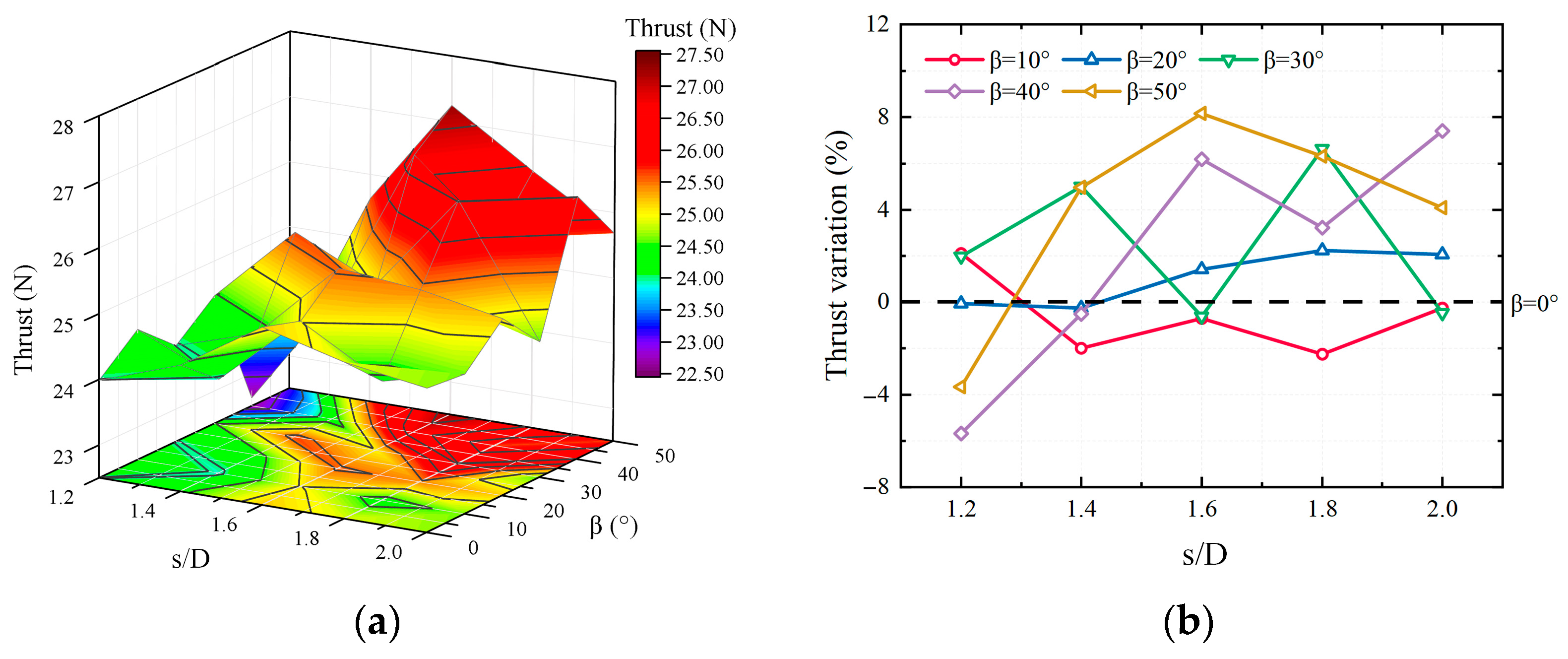
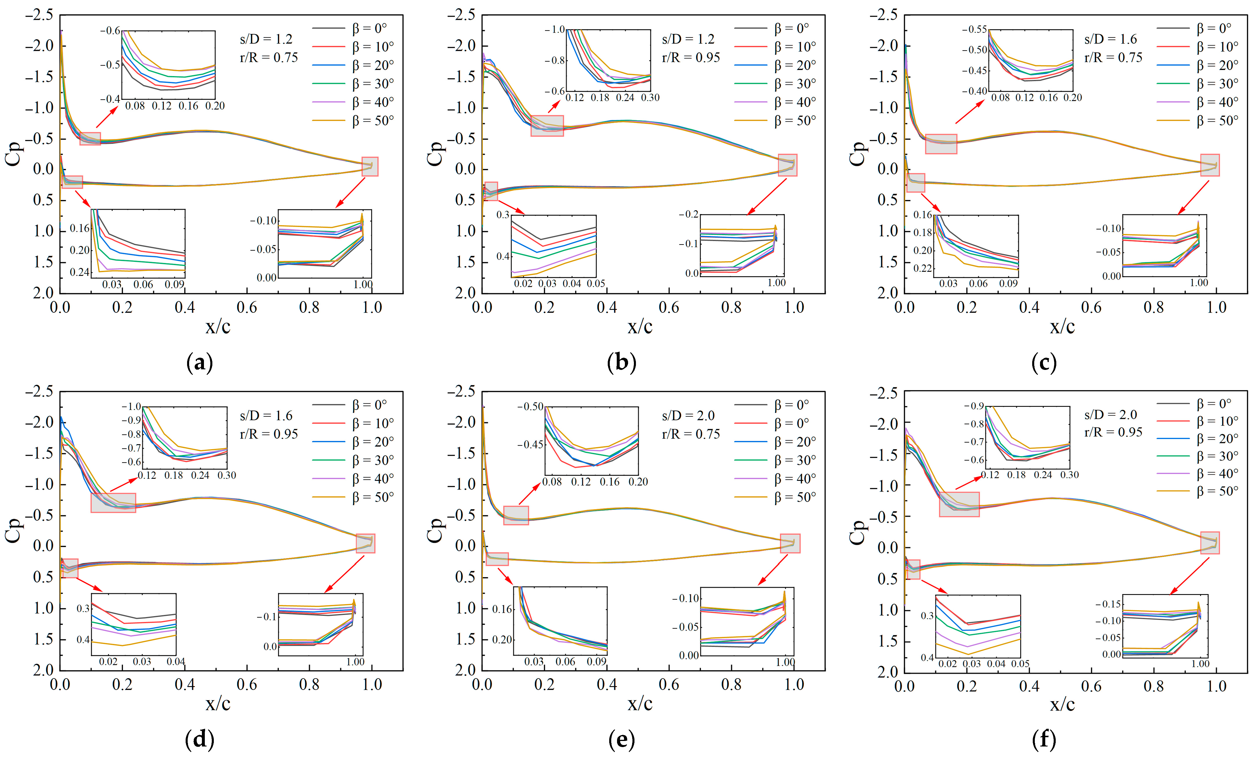
The optimal combination of rotor spacing and the dihedral angle will improve the aerodynamic performance of the inner tilted-rotor hexacopter with appropriate rotor interference to enhance thrust generation.
(2)
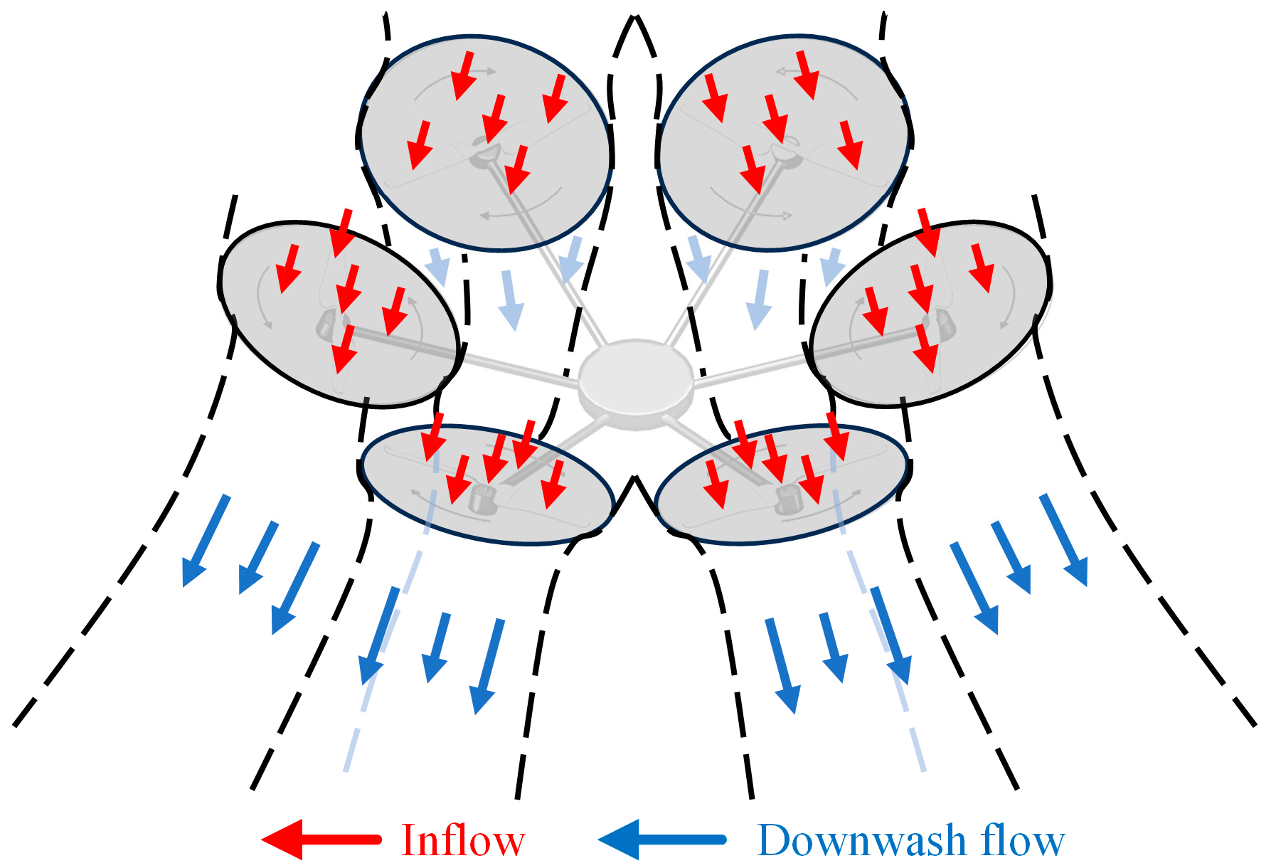
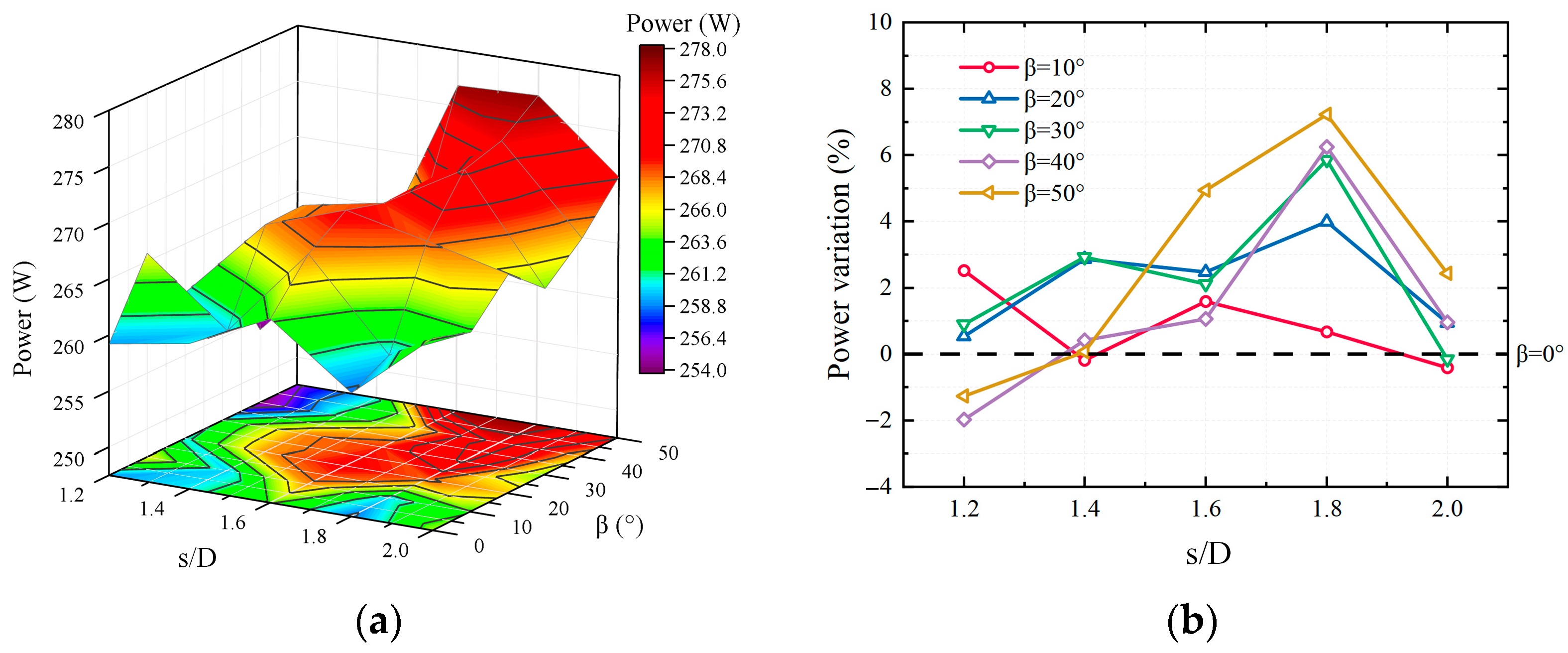
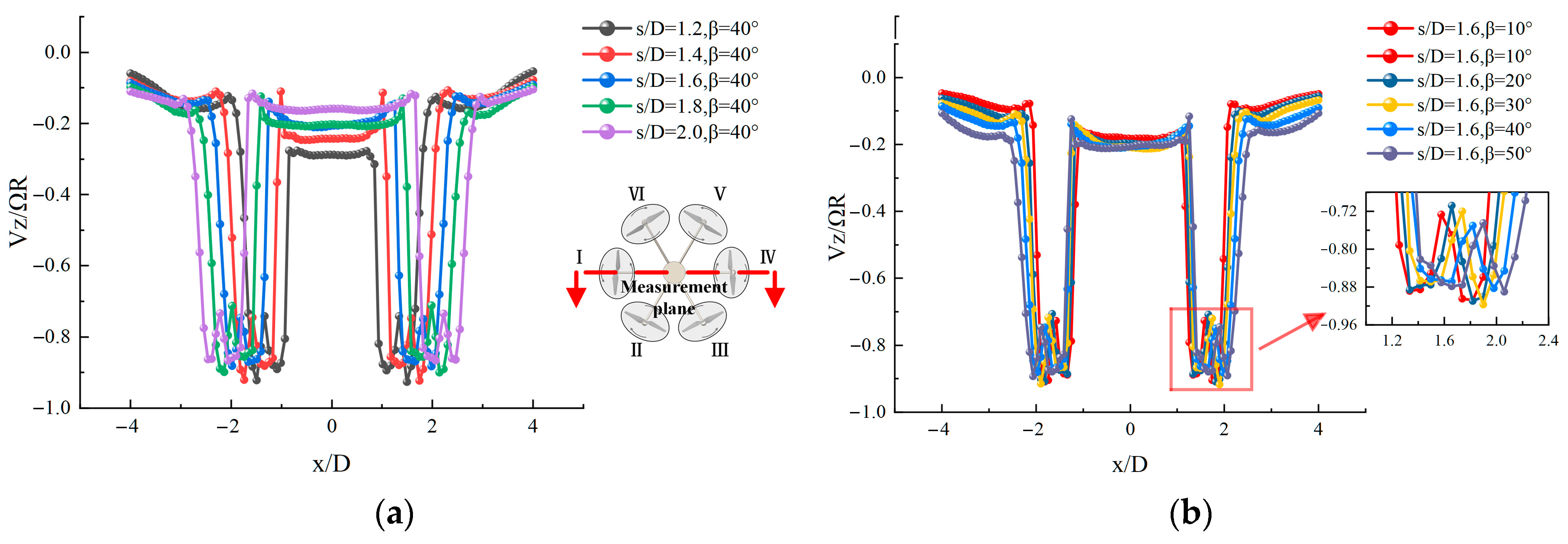
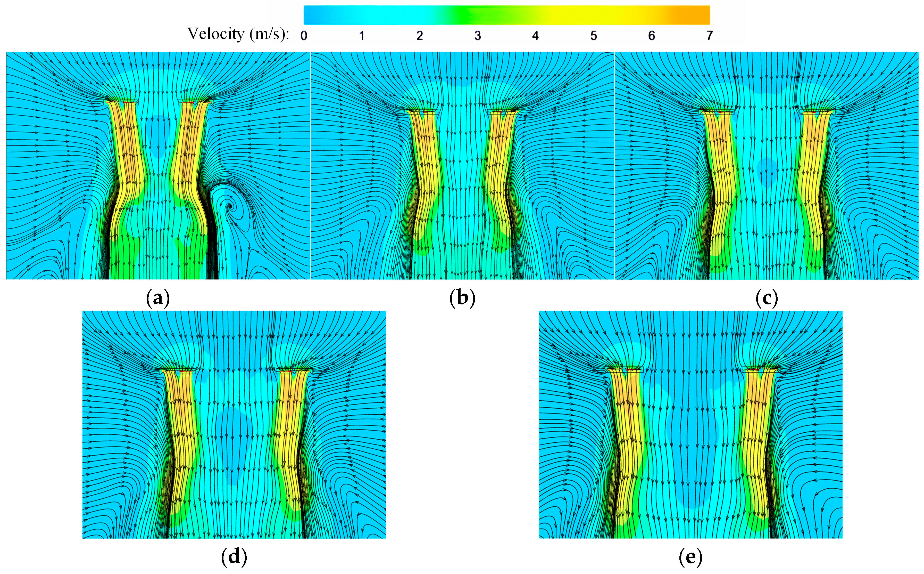
The inflows of the inner tilted-rotor hexacopter interfere with each other, which increases the complexity of the flow field. It reaches a steady state when the rotor spacing ratio (s/D) is less than 1.6, and aerodynamic interference is balanced with thrust increments and power decrements.
(3)
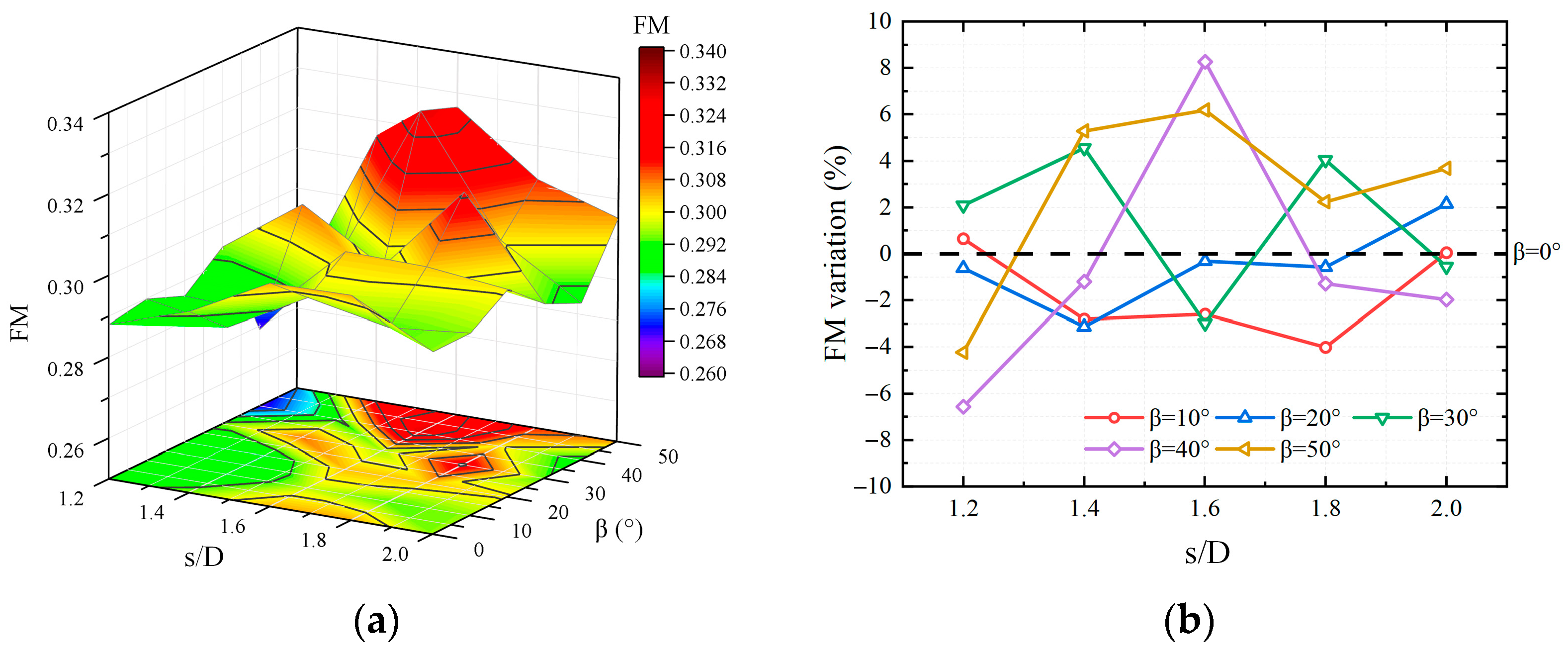
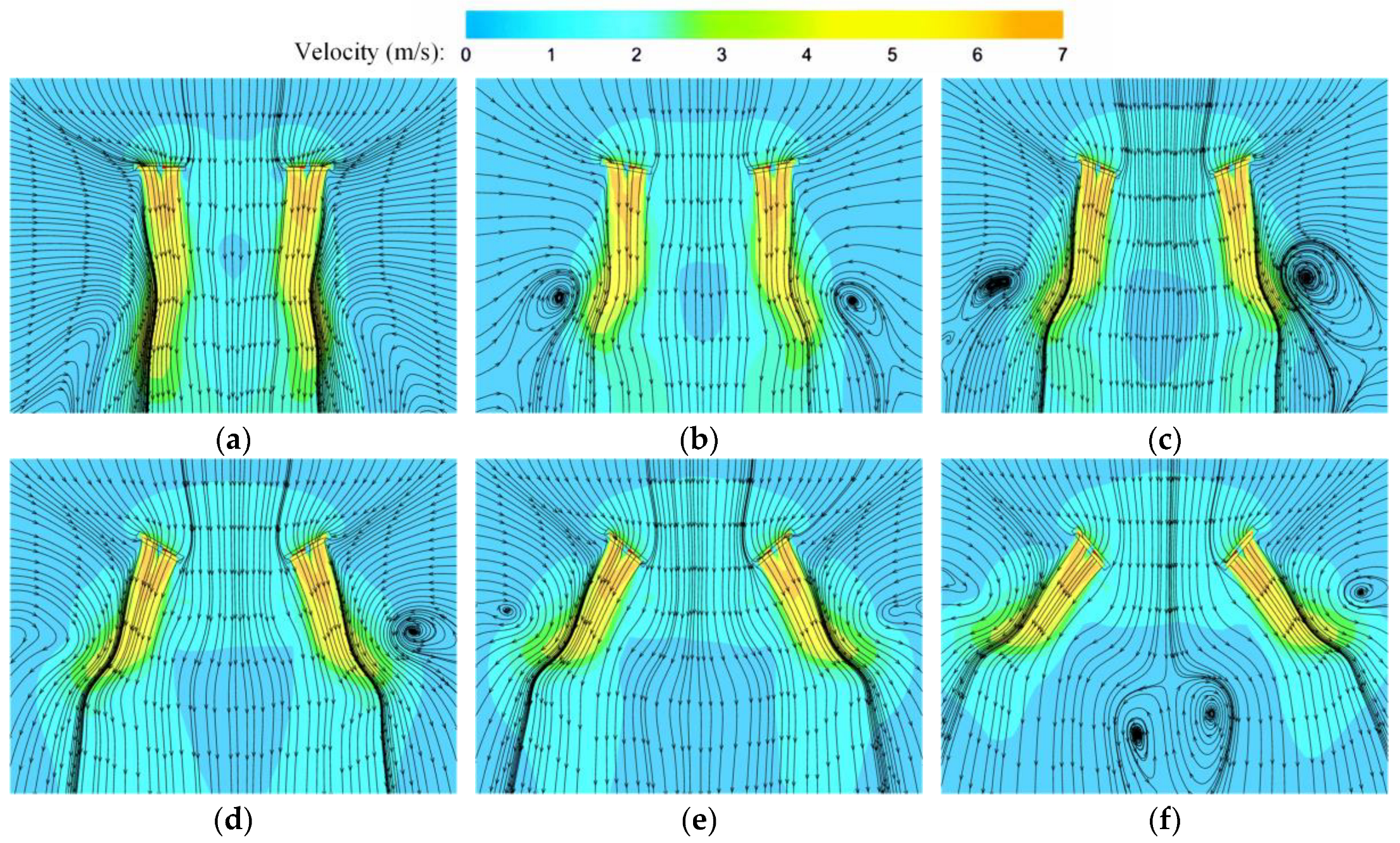
Smaller spacings lead to increased mutual interference between rotors, and the presence of vortices produces an unsteady wake behavior that reduces the overall aerodynamic efficiency, whereas larger spacings reduce this interference effect and improve aerodynamic efficiency.
(4)
For the inner tilted rotor, the thrust can be decomposed, which promotes a positive effect on the manipulation of the hexacopter. The experimental results show that it has a better performance compared to the conventional hexacopter, with s/D = 1.6 and β = 40°.
(5)
An optimal dihedral angle at a smaller spacing will improve the hover efficiency. However, too large of a dihedral angle will lead to increasing drag, which is not of benefit for thrust generation.
To optimize the best configuration of the inner tilted hexacopter, further study will involve more field flight tests combined with experiments and numerical simulations to meet specific needs, such as higher stability and efficiency, easy manipulation, or even better capability to resist wind gust. Understanding rotor interactions can provide valuable insights for the design of these kinds of novel inner tilted-rotor hexacopters.

Author Contributions

Investigation, review and editing, Y.L.; writing and software, C.L. All authors have read and agreed to the published version of the manuscript.

Funding

This research was supported by the National Natural Science Foundation of China (Grant No. 52275095) and the Fujian Provincial Industrial Robot Basic Components Technology Research and Development Center (2014H2004).

Data Availability Statement

All data are already included in the manuscript.

Acknowledgments

The authors thank the Key Laboratory of Fluid Power and Intelligent Electro-Hydraulic Control (Fuzhou University), Fujian Province University, for supplying the experimental field.

Conflicts of Interest

The authors declare no conflicts of interest.

References

  1. Floreano, D.; Wood, R.J. Science, Technology and the Future of Small Autonomous Drones. Nature 2015, 521, 460–466. [Google Scholar] [CrossRef] [PubMed]
  2. He, X.; Yang, X.; Luo, Z.; Guan, T. Application of Unmanned Aerial Vehicle (UAV) Thermal Infrared Remote Sensing to Identify Coal Fires in the Huojitu Coal Mine in Shenmu City, China. Sci. Rep. 2020, 10, 13895. [Google Scholar] [CrossRef]
  3. Zhu, M.; Yu, X.; Tan, H.; Yuan, J. Integrated High-Precision Monitoring Method for Surface Subsidence in Mining Areas Using D-InSAR, SBAS, and UAV Technologies. Sci. Rep. 2024, 14, 12445. [Google Scholar] [CrossRef]
  4. De Boer, G.; Calmer, R.; Jozef, G.; Cassano, J.J.; Hamilton, J.; Lawrence, D.; Borenstein, S.; Doddi, A.; Cox, C.; Schmale, J.; et al. Observing the Central Arctic Atmosphere and Surface with University of Colorado Uncrewed Aircraft Systems. Sci. Data 2022, 9, 439. [Google Scholar] [CrossRef]
  5. Achermann, F.; Stastny, T.; Danciu, B.; Kolobov, A.; Chung, J.J.; Siegwart, R.; Lawrance, N. WindSeer: Real-Time Volumetric Wind Prediction over Complex Terrain Aboard a Small Uncrewed Aerial Vehicle. Nat. Commun. 2024, 15, 3507. [Google Scholar] [CrossRef]
  6. Bodie, K.; Brunner, M.; Pantic, M.; Walser, S.; Pfandler, P.; Angst, U.; Siegwart, R.; Nieto, J. Active Interaction Force Control for Contact-Based Inspection with a Fully Actuated Aerial Vehicle. IEEE Trans. Robot. 2021, 37, 709–722. [Google Scholar] [CrossRef]
  7. Praveen, A.; Ma, X.; Manoj, H.; Venkatesh, V.L.; Rastgaar, M.; Voyles, R.M. Inspection-on-the-Fly Using Hybrid Physical Interaction Control for Aerial Manipulators. In Proceedings of the 2020 IEEE/RSJ International Conference on Intelligent Robots and Systems (IROS), Las Vegas, NV, USA, 24 October 2020; IEEE: Las Vegas, NV, USA, 2020; pp. 1583–1588. [Google Scholar]
  8. Tognon, M.; Chavez, H.A.T.; Gasparin, E.; Sable, Q.; Bicego, D.; Mallet, A.; Lany, M.; Santi, G.; Revaz, B.; Cortes, J.; et al. A Truly-Redundant Aerial Manipulator System With Application to Push-and-Slide Inspection in Industrial Plants. IEEE Robot. Autom. Lett. 2019, 4, 1846–1851. [Google Scholar] [CrossRef]
  9. Rashad, R.; Goerres, J.; Aarts, R.; Engelen, J.B.C.; Stramigioli, S. Fully Actuated Multirotor UAVs: A Literature Review. IEEE Robot. Autom. Mag. 2020, 27, 97–107. [Google Scholar] [CrossRef]
  10. Voyles, R.; Jiang, G. Hexrotor UAV Platform Enabling Dextrous Interaction with Structures—Preliminary Work. In Proceedings of the 2012 IEEE International Symposium on Safety, Security, and Rescue Robotics (SSRR), College Station, TX, USA, 5–8 November 2012; IEEE: College Station, TX, USA, 2012; pp. 1–7. [Google Scholar]
  11. Jiang, G.; Voyles, R. Hexrotor UAV Platform Enabling Dextrous Interaction with Structures-Flight Test. In Proceedings of the 2013 IEEE International Symposium on Safety, Security, and Rescue Robotics (SSRR), Linköping, Sweden, 21–26 October 2013; IEEE: Linkoping, Sweden, 2013; pp. 1–6. [Google Scholar]
  12. Jiang, G.; Voyles, R. A Nonparallel Hexrotor UAV with Faster Response to Disturbances for Precision Position Keeping. In Proceedings of the 2014 IEEE International Symposium on Safety, Security, and Rescue Robotics (2014), Hokkaido, Japan, 27–30 October 2014; IEEE: Hokkaido, Japan, 2014; pp. 1–5. [Google Scholar]
  13. Rajappa, S.; Ryll, M.; Bulthoff, H.H.; Franchi, A. Modeling, Control and Design Optimization for a Fully-Actuated Hexarotor Aerial Vehicle with Tilted Propellers. In Proceedings of the 2015 IEEE International Conference on Robotics and Automation (ICRA), Seattle, WA, USA, 26–30 May 2015; IEEE: Seattle, WA, USA, 2015; pp. 4006–4013. [Google Scholar]
  14. Giljarhus, K.E.T.; Porcarelli, A.; Apeland, J. Investigation of Rotor Efficiency with Varying Rotor Pitch Angle for a Coaxial Drone. Drones 2022, 6, 91. [Google Scholar] [CrossRef]
  15. Jiang, G.; Voyles, R.; Sebesta, K.; Greiner, H. Estimation and Optimization of Fully-Actuated Multirotor Platform with Nonparallel Actuation Mechanism. In Proceedings of the 2017 IEEE/RSJ International Conference on Intelligent Robots and Systems (IROS), Vancouver, BC, Canada, 24–28 September 2017; IEEE: Vancouver, BC, Canada, 2017; pp. 6843–6848. [Google Scholar]
  16. Jiang, G.; Voyles, R.M.; Choi, J.J. Precision Fully-Actuated UAV for Visual and Physical Inspection of Structures for Nuclear Decommissioning and Search and Rescue. In Proceedings of the 2018 IEEE International Symposium on Safety, Security, and Rescue Robotics (SSRR), Philadelphia, PA, USA, 6–8 August 2018; IEEE: Philadelphia, PA, USA, 2018; pp. 1–7. [Google Scholar]
  17. Michieletto, G.; Ryll, M.; Franchi, A. Fundamental Actuation Properties of Multirotors: Force–Moment Decoupling and Fail–Safe Robustness. IEEE Trans. Robot. 2018, 34, 702–715. [Google Scholar] [CrossRef]
  18. Deng, J.; Fan, F.; Liu, P.; Huang, S.; Lin, Y. Aerodynamic Characteristics of Rigid Coaxial Rotor by Wind Tunnel Test and Numerical Calculation. Chin. J. Aeronaut. 2019, 32, 568–576. [Google Scholar] [CrossRef]
  19. Lei, Y.; Zhao, X. The Aerodynamic Performance of a Novel Overlapping Octocopter in Hover. Aerospace 2024, 11, 737. [Google Scholar] [CrossRef]
  20. Zhang, Z.; Xie, C.; Wang, W.; An, C. An Experimental and Numerical Evaluation of the Aerodynamic Performance of a UAV Propeller Considering Pitch Motion. Drones 2023, 7, 447. [Google Scholar] [CrossRef]
  21. Rostami, M. Propeller Effects and Elasticity in Aerodynamic Analysis of Small Propeller-Driven Aircraft and UAVs. Aerospace 2024, 11, 664. [Google Scholar] [CrossRef]
  22. Vargas Loureiro, E.; Oliveira, N.L.; Hallak, P.H.; De Souza Bastos, F.; Rocha, L.M.; Grande Pancini Delmonte, R.; De Castro Lemonge, A.C. Evaluation of Low Fidelity and CFD Methods for the Aerodynamic Performance of a Small Propeller. Aerosp. Sci. Technol. 2021, 108, 106402. [Google Scholar] [CrossRef]
  23. Aziz, A.; Shi, Y. Impact of Rotor-to-Rotor Interactions on the Tonal Noise Characteristics of Different Octocopter Configurations. Aerospace 2024, 11, 1022. [Google Scholar] [CrossRef]
  24. Ventura Diaz, P.; Yoon, S. High-Fidelity Computational Aerodynamics of Multi-Rotor Unmanned Aerial Vehicles. In Proceedings of the 2018 AIAA Aerospace Sciences Meeting, Kissimmee, FL, USA, 8–12 January 2018; American Institute of Aeronautics and Astronautics: Kissimmee, FL, USA, 2018. [Google Scholar]
  25. Garofano-Soldado, A.; Sanchez-Cuevas, P.J.; Heredia, G.; Ollero, A. Numerical-Experimental Evaluation and Modelling of Aerodynamic Ground Effect for Small-Scale Tilted Propellers at Low Reynolds Numbers. Aerosp. Sci. Technol. 2022, 126, 107625. [Google Scholar] [CrossRef]
  26. Wilcox, D.C. Turbulence Modeling for CFD, 2nd ed.; DCW Industries: La Cañada, CA, USA, 2000; ISBN 978-0-9636051-5-3. [Google Scholar]
  27. Menter, F.R. Two-Equation Eddy-Viscosity Turbulence Models for Engineering Applications. AIAA J. 1994, 32, 1598–1605. [Google Scholar] [CrossRef]
  28. Kutty, H.; Rajendran, P. 3D CFD Simulation and Experimental Validation of Small APC Slow Flyer Propeller Blade. Aerospace 2017, 4, 10. [Google Scholar] [CrossRef]
  29. Paz, C.; Suárez, E.; Gil, C.; Vence, J. Assessment of the Methodology for the CFD Simulation of the Flight of a Quadcopter UAV. J. Wind Eng. Ind. Aerodyn. 2021, 218, 104776. [Google Scholar] [CrossRef]
  30. Li, C.; Xue, C.; Bai, Y. Experimental Investigation on Aerodynamics of Nonplanar Rotor Pairs in a Multi-Rotor UAV. In Proceedings of the 2019 14th IEEE Conference on Industrial Electronics and Applications (ICIEA), Xi’an, China, 19–21 June 2019; IEEE: Xi’an, China, 2019; pp. 911–915. [Google Scholar]
  31. Dougherty, S.; Oo, N.L.; Zhao, D. Effects of Propeller Separation and Onset Flow Condition on the Performance of Quadcopter Propellers. Aerosp. Sci. Technol. 2024, 145, 108837. [Google Scholar] [CrossRef]
  32. Sagaga, J.; Lee, S. High-Fidelity Computational Study of Aerodynamic Noise of Side-by-Side Rotor in Full Configuration. J. Sound Vib. 2024, 592, 118607. [Google Scholar] [CrossRef]
  33. Yoon, S.; Lee, H.C.; Pulliam, T.H. Computational Analysis of Multi-Rotor Flows. In Proceedings of the 54th AIAA Aerospace Sciences Meeting, San Diego, CA, USA, 4–8 January 2016; American Institute of Aeronautics and Astronautics: San Diego, CA, USA, 2016. [Google Scholar]
  34. Chiew, J.J.; Aftosmis, M.J. Efficient Simulation of Multi-Rotor Vehicles with Low Reynolds Number Propellers. In Proceedings of the 2018 Applied Aerodynamics Conference, Atlanta, GA, USA, 25–29 June 2018; American Institute of Aeronautics and Astronautics: Atlanta, GA, USA, 2018. [Google Scholar]
  35. Fengbo, Y.; Xinyu, X.; Ling, Z.; Zhu, S. Numerical Simulation and Experimental Verification on Downwash Air Flow of Six-Rotor Agricultural Unmanned Aerial Vehicle in Hover. Int. J. Agric. Biol. Eng. 2017, 10, 41–53. [Google Scholar] [CrossRef]
  36. Shen, A.; Zhou, S.; Peng, S. Atmospheric Environment Detection Method Based on Multi-Rotor Uav Platform. Int. Arch. Photogramm. Remote Sens. Spat. Inf. Sci. 2018, XLII-3/W5, 67–71. [Google Scholar]
  37. Grande, E.; Shubham, S.; Avallone, F.; Ragni, D.; Casalino, D. Computational Aeroacoustic Study of Co-Rotating Rotors in Hover. Aerosp. Sci. Technol. 2024, 153, 109381. [Google Scholar] [CrossRef]
  38. Zhang, W.; Sun, J.; Wang, L.; Wu, J.; He, L. Rotor Airfoil Aerodynamic Design Method and Wind Tunnel Test Verification. Chin. J. Aeronaut. 2020, 33, 2123–2132. [Google Scholar] [CrossRef]
  39. Jing, S.M.; Zhao, G.Q.; Zhao, Q.J. Numerical Research on Secondary Peak of Aerodynamic Forces of Airfoil Under Dynamic Stall. J. Nanjing Univ. Aeronaut. Astronaut. 2022, 54, 191–202. (In Chinese) [Google Scholar] [CrossRef]
  40. Okulov, V.L.; Sørensen, J.N. Stability of Helical Tip Vortices in a Rotor Far Wake. J. Fluid Mech. 2007, 576, 1–25. [Google Scholar] [CrossRef]
  41. Inagaki, K.; Hamba, F. Modeling the Energy Flux Enhanced in Rotating Inhomogeneous Turbulence. In Progress in Turbulence VIII, Proceedings of the iTi Conference in Turbulence 2018, Bertinoro, Italy, September 2018; Örlü, R., Talamelli, A., Peinke, J., Oberlack, M., Eds.; Springer International Publishing: Cham, Switzerland, 2019; pp. 139–144. [Google Scholar]
Figure 1. The 3D geometry of the propellers. (a) Top view; (b) front view; and (c) chord and pitch distribution.
Aerospace 12 00317 g001
Figure 2. Hexacopter with inner tilted-rotor configuration.
Aerospace 12 00317 g002
Figure 3. The schematic structure. (a) Top view; (b) partial side view.
Aerospace 12 00317 g003
Figure 4. Aerodynamic interference of inner tilted-rotor hexacopter.
Aerospace 12 00317 g004
Figure 5. Experimental setup.
Aerospace 12 00317 g005
Figure 6. Computational domains. (a) The boundary conditions of the CFD settings; (b) the dimensions of the computational domain.
Aerospace 12 00317 g006
Figure 7. Simulation results of thrust and torque with different meshes.
Aerospace 12 00317 g007
Figure 8. Mesh structure used in this study.
Aerospace 12 00317 g008
Figure 9. Comparison of experimental data with CFD data. (a) s/D = 1.6; (b) s/D = 2.0.
Aerospace 12 00317 g009
Figure 10. Thrust variation. (a) The 3D distribution of the thrust; (b) the thrust variation compared with a conventional hexacopter.
Aerospace 12 00317 g010
Figure 11. Power variation. (a) The 3D distribution of the power; (b) the power variation compared to a conventional hexacopter.
Aerospace 12 00317 g011
Figure 12. FM variation. (a) The 3D distribution of the FM; (b) the FM variation compared to a conventional hexacopter.
Aerospace 12 00317 g012
Figure 13. The velocity distribution at 0.4D below the hexacopter. (a) β = 40° and s/D varying from 1.2 to 2.0; (b) s/D = 1.6 and β varying from 10° to 50°.
Aerospace 12 00317 g013
Figure 14. Velocity and streamline distributions at β = 0° (Arrows represent the direction of streamlines). (a) s/D = 1.2; (b) s/D = 1.4; (c) s/D = 1.6; (d) s/D = 1.8; and (e) s/D = 2.0.
Aerospace 12 00317 g014
Figure 15. Velocity and streamline distribution of rotor cross-section for different dihedral angles at s/D = 1.6 (Arrows represent the direction of streamlines). (a) β = 0°; (b) β = 10°; (c) β = 20°; (d) β = 30°; (e) β = 40°; and (f) β = 50°.
Aerospace 12 00317 g015
Figure 16. Pressure coefficients. (a) s/D = 1.2, r/R = 0.75; (b) s/D = 1.2, r/R = 0.95; (c) s/D = 1.6, r/R = 0.75; (d) s/D = 1.6, r/R = 0.95; (e) s/D = 2.0, r/R = 0.75; and (f) s/D = 2.0, r/R = 0.95.
Aerospace 12 00317 g016
Figure 17. Vorticity distribution at s/D = 1.6. (a) β = 0°; (b) β = 10°; (c) β = 20°; (d) β = 30°; (e) β = 40°; and (f) β = 50°.
Aerospace 12 00317 g017
Table 1. Propeller parameters.
ParametersUnitValue
Diameterm0.4
Blade Pitchm0.157
Chord (0.75R)m0.026
Chord (average)m0.035
Weightkg0.015
Uniform Thickness%2.5
Uniform Curvature%4.5
Solidity%0.128
Table 2. The main parameters of the test bench.
FacilityModelScopeAccurate Value
Weight SensorDYZ-1010–10 N0.05%
Hall SensorNJK-8001C10–9999 RPM0.1%
Torque SensorDYJN-1040–0.5 N·m0.05%
Electronic Speed ControlYK-PWM10411–99 KHz1%
Table 3. The operating conditions tested in the experimental study.
ParametersUnitValue
Propeller speed ( Ω )rpm2200
Dihedral angle ( β )deg0, 10, 20, 30, 40, 50
Rotor spacing ratio (s/D)-1.2, 1.4, 1.6, 1.8, 2.0
Table 4. Mesh sensitivity of isolated rotor.
Mesh ModelSurface Mesh
(mm)
Total Elements
(×104)
Thrust
(N)
Torque
(N·m)
Averaged
y-Plus
Mesh 1629.363.300.09332.82
Mesh 2471.063.340.09032.66
Mesh 32110.703.350.08832.34
Mesh 41137.373.350.08831.39
Table 5. The mesh sensitivity study of the hexacopter.
Mesh ModelRotational
Domain Meshes (×104)
Stationary
Domain Meshes (×104)
Total Number of Meshes (×104)Thrust
(N)
Coarse mesh476.70606.211082.9123.97
Medium mesh606.25852.361458.6124.04
Fine mesh760.531009.821770.3524.06
Disclaimer/Publisher’s Note: The statements, opinions and data contained in all publications are solely those of the individual author(s) and contributor(s) and not of MDPI and/or the editor(s). MDPI and/or the editor(s) disclaim responsibility for any injury to people or property resulting from any ideas, methods, instructions or products referred to in the content.

