Abstract
To improve the thermal protection effect of an opposing jet, a novel thermal protection technology (i.e., an opposing jet combined with magnetohydrodynamic (MHD) control technology) is proposed in this study. Considering the flight conditions of an ELECTRE vehicle and the unsteady state of the opposing jet, we employed the time-accurate nonequilibrium N-S equations coupled with a low-magnetic-Reynolds-number model to explore the jet characteristics, thermal protection effects, and aerodynamic drag characteristics of this novel technology. Two jet conditions (PR2.53 and PR5.07) and four magnetic field conditions (no-MHD, B0 = 1 T, 2 T, and 4 T) were employed. The results show that the introduction of a magnetic field can guide the flow of the opposing jet by reconstructing the shock, where the reattachment shock is pushed away from the surface and the shock standoff distance (SSD) increases. Compared with the opposing jet and the MHD control technologies, this novel technology can provide a better thermal protection effect. In particular, it enables a long penetration mode (LPM) jet, which aggravates the aerodynamic heating environment around the vehicle at lower flow rates to provide effective thermal protection for the vehicle. Moreover, this novel technology can achieve effective thermal protection without increasing the aerodynamic drag at an appropriate jet mass flow rate and a magnetic field strength. For example, under the B0 = 2 T magnetic field, the ratios of peak wall heat flux for the two technologies (the MHD control technology and the PR2.53 jet combined MHD control technology) are 0.908 and 0.820, respectively, whereas the ratios of average drags for the two technologies are 1.235 and 0.993, respectively.
1. Introduction
Achieving long-term flight in hypersonic vehicles has become a strategic requirement for global power [1]. Extreme aerodynamic heating caused by high flight speeds is one of the most significant obstacles in the development of hypersonic vehicles [2], causing traditional passive or semi-passive thermal protection methods (such as ablation, heat-shield tiles, etc.) to fail. Therefore, the active thermal protection method which actively controls the flow field around the vehicle has become the main approach to solving the aerodynamic heating problem of future hypersonic vehicles [3]. The opposing jet [4] method is one of the active thermal protection methods, where cooling gas is injected into the opposite direction of the freestream to push the shock away from the vehicle surface.
As revealed in experiments by Hayashi [5] and Daso [6], there are two jet modes of the opposing jet, i.e., the long penetration mode (LPM) and the short penetration mode (SPM). LPM jets appear at a low mass flow rate, where the jet penetrates a long distance forward in a slender cylindrical shape and the freestream shock becomes a conical shock. A SPM jet appears at a high mass flow rate, with a small jet penetration distance and a short barrel shape. However, the thermal protection effects of SPM jets and LPM jets are completely opposite. Experimental results [5,6] indicate that LPM jets not only fail to provide effective thermal protection but also further exacerbate aerodynamic heating, whereas SPM jets can offer excellent thermal protection. Subsequently, researchers [7,8] confirmed this conclusion by using numerical simulations.
Although an SPM jet can effectively reduce aerodynamic heating, it requires a high mass flow rate of the cooling gas, which is not beneficial for the long-term cruise of vehicles. Therefore, improving the thermal protection efficiency of opposing jets and achieving effective thermal protection using a low mass flow rate have become popular research topics. Several researchers have proposed different jet structures, such as micro-jets [9,10] and combined opposing jets [11]. Other researchers have suggested an opposing jet combined with other technologies, such as spikes [12,13,14,15] and cavities [16,17,18]. However, these technologies significantly modify the surface structure of vehicles, which reduces their reliability and potentially increases the risks they encounter.
Researchers have explored the physical mechanism of LPM jets to explain why they cannot provide thermal protection, and they found that the jet characteristics of LPM jets are more complicated, owing to their strong instability compared with SPM jets. Experiments [6] have shown that the shock schlieren of LPM jets is blurred, which can be explained by the shock oscillation. Fujita [19] and Deng [20] found that the shock standoff distance of an LPM jet oscillates with high amplitude and low frequency by using a numerical simulation method with an unsteady RANS model. Kim [21] summarized the LPM oscillation mechanism: diamond shock occurs–fluid impulse increases–penetration length increases–pressure in recirculation region decreases–jet expansion ratio increases–Mach disk is formed–fluid impulse decreases–penetration length decreases. Our previous studies [22] further revealed that the key to jet instability is the breakdown of the recirculation region. Experiments and our previous studies have also revealed that the reattachment shock in LPM jets resulted in severe aerodynamic heating of the shoulder of the vehicle. If the reattachment shock can be pushed away from the surface of vehicle, the thermal protection efficiency of the opposing jet can be significantly improved. This paper intends to introduce MHD control technology for this purpose.
MHD control technology can control the shock shape by controlling the movement of plasma around the vehicle [23], and it has the advantage of not affecting the vehicle’s surface structure. The German Aerospace Center [24] assembled an experiment at the high-enthalpy shock tunnel Göttingen with a Mach number of 8.2 and found that the SSD was increased by 4.6 times under 4.5 T. Ziemer [25] conducted an experiment in an electromagnetic shock tube with a freestream velocity of 6890 m/s and observed that the SSD increased as the magnetic field strength increased. Smith [26] conducted a series of experiments in an X2 expansion shock tunnel and found that the SSD increased after the introduction of a magnetic field. Smith [26,27] also made great efforts in MHD drag force measurements, realizing the measurement of Lorentz force by mounting an accelerometer attached to the rear of the magnet for measuring streamwise motion. Recently, the application of MHD control to shock wave/boundary layer interactions has attracted the interest of researchers. Gong [28] conducted an experiment on a wedge in a Mach 7 hypersonic shock tunnel and observed that the shocks increased and moved forward after introducing a magnetic field. Jiang [29] conducted a parametric study of high-enthalpy flow over a hollow cylinder/flare model with MHD control and found that N-type controlled the largest reduction in the peak wall heat flux. Luo [30] investigated the MHD control effects over a 25°/55°double cone and found that the MHD control mitigated the aerodynamic heat and the thermal protection effect was enhanced with increasing magnetic field strength. Wang [31] proposed the application of MHD control technology to the inlet of the airbreathing hypersonic vehicles and found that the combination of weak leading-edge shock and strong magnetic field can obtain a better compression effect. Anyway, the above experimental and theoretical studies have well verified that MHD control technology is capable of controlling hypersonic flow fields containing plasma.
In this study, we propose a novel thermal protection technology: an opposing jet combined with MHD control. The purpose is to improve the thermal protection efficiency of the opposing jet by introducing MHD control technology to control the flow of the opposing jet. Based on our previous investigations of opposing jets [22], the ELECTRE vehicle was used as the research object, which flies at an altitude of 53.3 km with a Mach number of 13. The jet characteristics, thermal protection performance, and aerodynamic drag of an opposing jet combined with MHD control technology were explored using a numerical simulation method. Considering the unsteady state of the opposing jet, thermochemical nonequilibrium, and chemical reactions existing in hypersonic flows, the time-accurate nonequilibrium N-S equations coupled with a low-magnetic-Reynolds-number model were applied in this study.
2. Numerical Approach
This study focuses on the conditions of hypersonic vehicle flights at high Mach numbers and altitudes, which are associated with chemical reactions, chemical nonequilibrium, and even thermal nonequilibrium phenomena. Thus, the two-temperature model [32] is adopted in this study, which can describe the thermochemical nonequilibrium effect around hypersonic vehicles. The low magnetic Reynolds number approximation is applied for the coupling magnetic field, where the magnetic Reynolds number is on the order of unity or less [33], indicating that the induced field can be neglected compared to the applied field. In addition, the time-accurate method is applied, considering the instability of the opposing jet. And the laminar model is adopted due to the calculated Reynolds number, 60,800.
Finally, the governing equations are time-accurate thermochemical nonequilibrium N-S equations (two-temperature model) coupled with the low magnetic Reynolds number approximation, including the continuity equation for the individual species (Equation (1)), momentum equation (Equation (2)), total energy equation (Equation (3)), and vibro-electronic energy equation (Equation (4)), which are written as follows [34]:
where for the detailed calculation of the chemical source term, the thermodynamic and transport properties of individual species and a mixture, refer to reference [34].
Ignoring the electric field, both J·E and γ(J·J)/σ are equal to zero, and the electric current density can be simplified as
Electrical conductivity can be calculated using empirical formulas, such as the Bush and Raizer models [35], and can be written as
Referring to the investigations of Otsu [36] and Nagata [37], the parameters were set as = 250 S/m, T0 = 25,000 K, and n = 2.
In this study, a dipole magnetic field was applied without considering the electrical conductivity of wall, which can be seen as a simplified form generated by a solenoid. Referring to previous studies [38], an externally magnetic field B is assumed to be produced by a dipole magnet, which is defined as
The center of the dipole magnet is (x0, y0, z0). Assuming that both the dipole magnet axis and the flow field axis are located in the Z plane and the angle between them is θ, the vectors m and r should be expressed as
Finally, according to Equations (8) and (9), the magnetic field distribution of a dipole magnet in the Cartesian coordinate system can be expressed as
3. Computational Model Validation
The computational model validations were based on the Hy2Foam solver [39], in which a 3D dipole magnetic field expressed in Equation (10) was implanted by authors. Referring to Ding’s investigations [40], a RAM-C blunt cone was used for the code validation of governing equations. The radius of the spherical nose of the RAM-C blunt cone was 0.1524 m, the total length was 1.295 m, and the cone half-angle was 9°. The flight altitude of the RAM-C blunt cone was 71 km, and its velocity was 7650 m/s. According to the flight altitude, freestream conditions can be calculated using the 1976 US standard atmosphere (i.e., the static pressure is 4.737 Pa and the static temperature is 217.35 K). The wall was set as the velocity and temperature slip, in which the momentum accommodation coefficient and the thermal accommodation coefficient were set to unity, and the wall temperature was defined as an isothermal surface with 1500 K.
The 11-species Park chemical kinetic model adopted in Ding’s studies [40] was employed for this validation. Raizer (Equation (7)) and Bush (Equation (6)) electrical conductivity models were employed for following validation.
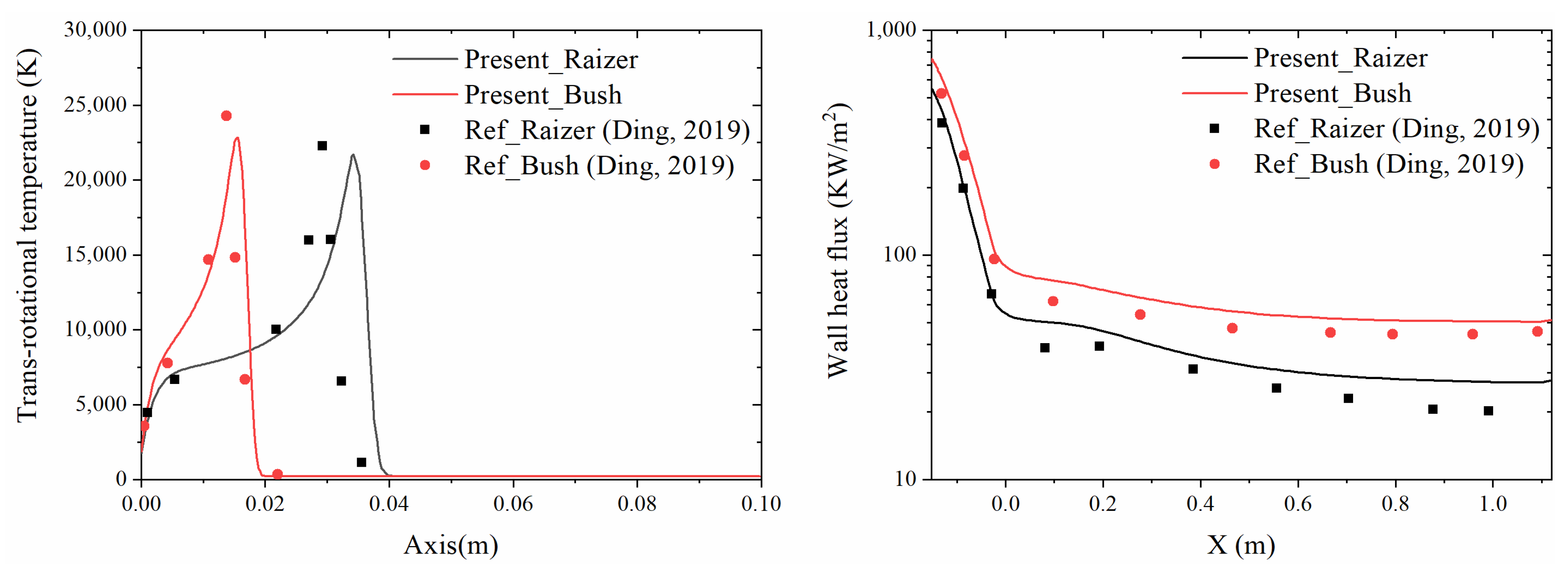
Figure 1 shows the trans-rotational temperature on the axis (left) and the wall heat flux (right) with the Raizer and Bush electrical conductivities, respectively. As shown, the distribution trend in trans-rotational temperature, calculated using the Raizer and Bush electrical conductivities, is consistent with that of reference [40]. Additionally, the results obtained both at present and in the reference indicate that the SSD calculated using the Raizer model is larger than that calculated using the Bush model, and that the wall heat flux predicted by the Raizer model is lower than that predicted by the Bush model. However, there are slight differences between the results of this study and those of Ding [40]. For instance, the peak trans-rotational temperatures calculated in the present study are slightly smaller than those reported in reference, and the SSDs are slightly larger than those in the reference. This may be due to the fact that the electric field generated by the plasma was not considered in this study.
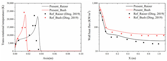
Figure 1.
Computational model validation, trans-rotational temperature (left), and wall heat flux (right) [40].
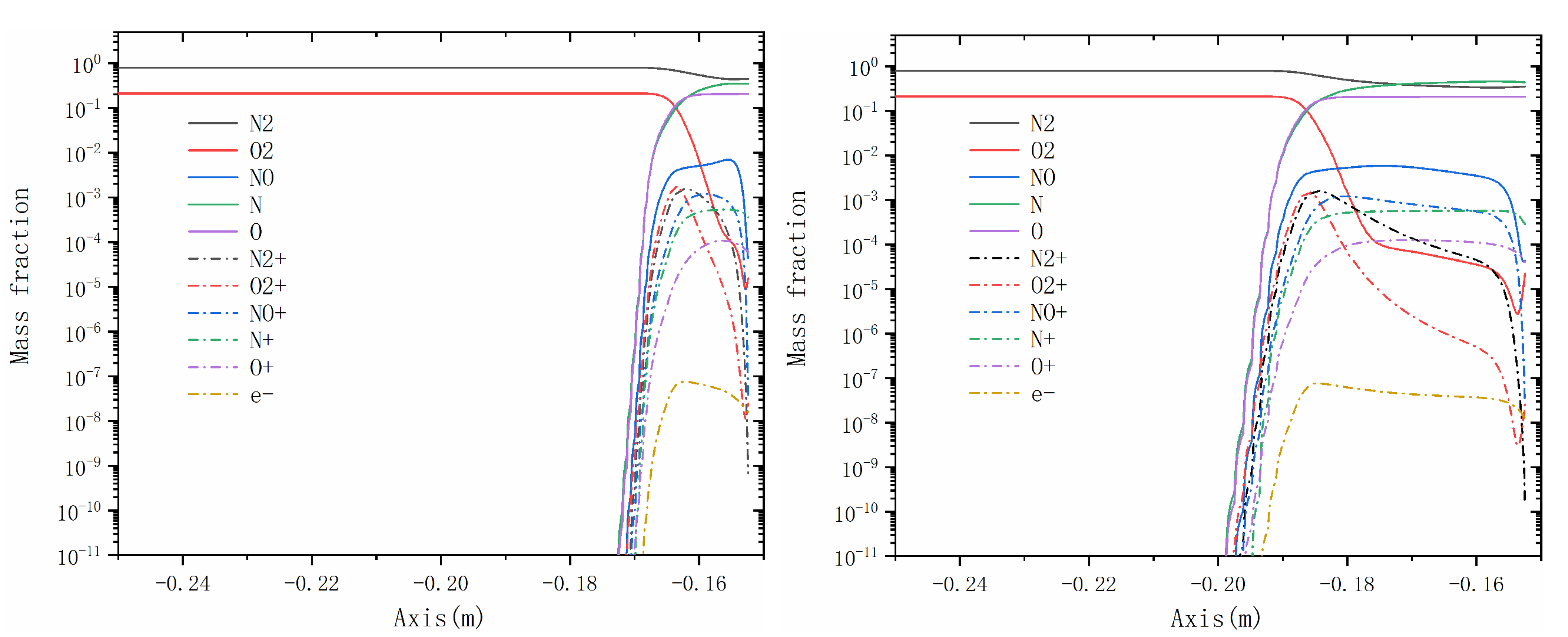
Figure 2 presents the plasma distribution along the axis under no–MHD (left) and B0 = 0.5 T conditions (right), respectively. It can be clearly observed that after introducing the magnetic field, the distance between the shock and the stagnation point increases. The magnetic field slows down the flow of plasma, enabling more thorough chemical reactions such as dissociation, exchange, and ionization. Consequently, the plasma distribution near the wall is not entirely identical between conditions with and without a magnetic field. For instance, the concentration of nitrogen near the surface is notably higher in the absence of a magnetic field compared to the that with a magnetic field.
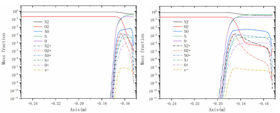
Figure 2.
Plasma distribution along the axis, no-MHD (left), and B0 = 0.5 T (right).
4. Physical Description
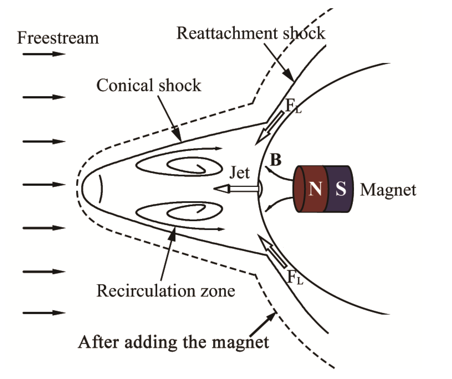
Figure 3 presents the schematic diagram of the LPM jet combined with MHD control technology applied to the vehicles. The jet pushes the shock away from the head of vehicle, resulting in a conical shock. However, the conical shock reattaches to the shoulder of vehicle, generating a reattachment shock that causes severe aerodynamic heating in the shoulder of vehicle. The magnet placed inside the nose of vehicle and the magnetic field interacts with the plasma in the flow field, generating a Lorentz force that can push the shock away from the vehicle surface.
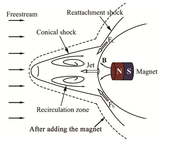
Figure 3.
Schematic diagram of the LPM jet combined with MHD control technology.
Based on the ELECTRE vehicle flight experiments [41] and our previous investigation of opposing jets [22], this section considers the ELECTRE vehicle as a research object, focusing on the thermal protection effect and the aerodynamic drag characteristics of an opposing jet combined with MHD control technology. The effects of the jet mass flow rate and the magnetic field strength were explored.
4.1. Geometric Model and Grid
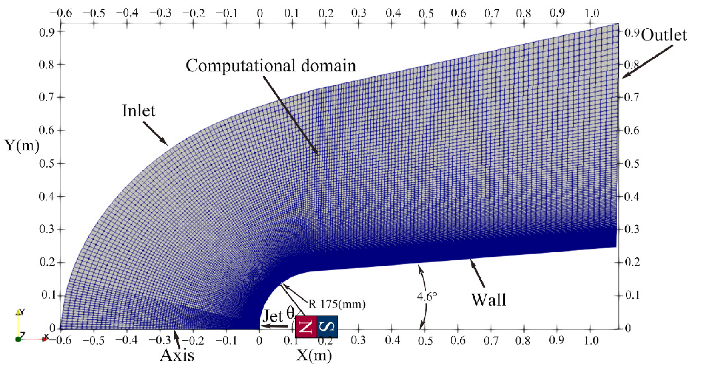
Figure 4 shows the grid model and boundaries of computational domain of the opposing jet combined with MHD control technology applied to the ELECTRE vehicle. The head radius of the ELECTRE vehicle was 175 mm, the cone half angle was 4.6°, and the total length was defined as 1100 mm for comparison with our previous study [22]. A dipole magnetic field was applied, where the dipole magnet center was located at the spherical center of the ELECTRE vehicle, and the dipole magnet axis coincided with the axis of the ELECTRE vehicle. Under these conditions, the magnetic field distribution around the ELECTRE vehicle is axisymmetric. Therefore, a 2D axisymmetric grid model was used in the following investigation.

Figure 4.
Grid model and boundaries.
The boundaries of the ELECTRE vehicle’s external flow field include the Inlet, Outlet, Wall and Jet. The Inlet depends on the freestream conditions, the Outlet is the flow field outlet, the Wall is the surface of ELECTRE vehicle, and the Jet is the inlet of opposing jet. A fully structured grid was applied, and the grid convergence was validated in our previous study [22]. Finally, the grid nodes 250 × 180 normal to and along the surface were adopted. The thickness of the first-layer grid near the wall was 6 × 10⁻⁶ m, corresponding to a cell Reynolds number of 1.07, which was sufficient to ensure the calculation accuracy of aerodynamic heat.
4.2. Cases Design and Boundary Conditions
Table 1 lists the boundary and magnetic field conditions. The flight conditions of the ELECTRE vehicle are derived from flight experiments [41], which flies at 53.3 km with a velocity of 4230 m/s. According to the flight conditions, the calculated Mach number is 13, the static pressure is 52.8 Pa, and the static temperature of the Inlet is 265 K, respectively. In order to compare with our previous investigation [22], two jet conditions were used: PR2.53 and PR5.07. The pressure ratio (PR) is defined as the ratio of the jet total pressure to the total pressure after a freestream shock. The species of Inlet is air, defined as consisting of 78% nitrogen (N2) and 22% oxygen (O2) in this paper. The species of Jet is pure N2. The Mach numbers, static temperature, and jet radius of two jet conditions are 1, 343 K, and 7 mm, respectively. The surface temperature of the ELECTRE vehicle was set to 343 K. Four magnetic field conditions were employed to explore the influence of the magnetic field strength: no-MHD (no magnet), B0 = 1 T, 2 T, and 4 T.

Table 1.
Boundary conditions and magnetic field conditions.
5. Results and Discussions
5.1. Flowfield Analysis with MHD Control Technology
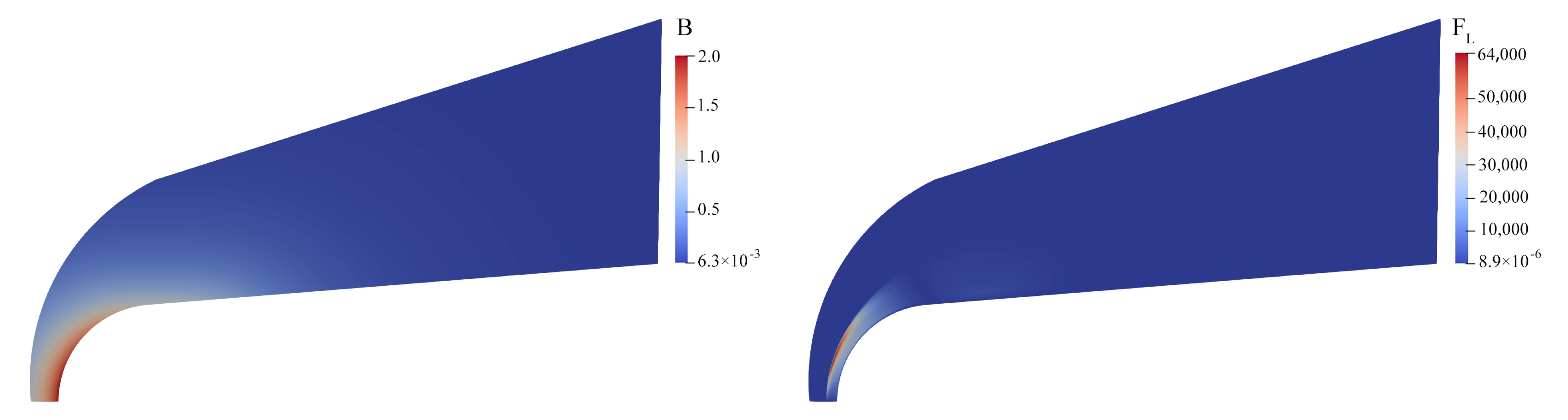
Figure 5 shows the magnetic field (left) and Lorentz force (right) distributions around the ELECTRE vehicle using only MHD control technology, where the magnetic field strength at the reference point is 2 T (B0 = 2 T). The reference point is located on the dipole magnet axis, and the distance r0 between the reference point and the center of the dipole magnet is equal to the radius of the head of ELECTRE vehicle. The Lorentz force in the shoulder region is larger than that in other regions, indicating that the force in the shoulder region dominates the process of the shock being pushed away from the surface. The distributions of the magnetic field and the Lorentz force are consistent with those obtained in previous studies [35,38], further validating the accuracy of the implanted magnetic field and the calculation code.
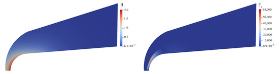
Figure 5.
Magnetic field (left) and Lorentz force (right) around ELECTRE at B0 = 2 T.
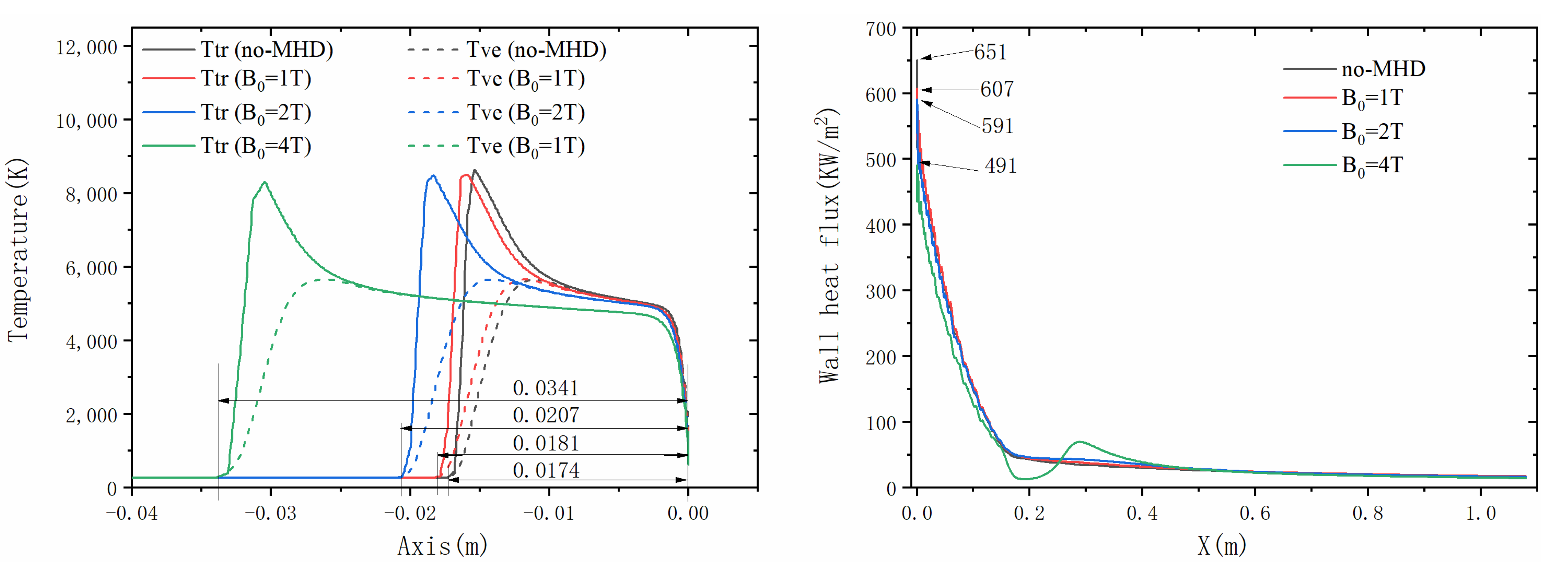
Figure 6 shows the trans-rotational and vibro-electronic temperatures along the axis (left) and the wall heat flux (right) under no-MHD, B0 = 1 T, 2 T, and 4 T conditions. The shock position can be defined as the location at which the temperature undergoes a sudden change along the axis. The SSD values at no-MHD and B0 = 1 T, 2 T, and 4 T magnetic fields are 0.0174, 0.0181, 0.0207, and 0.0341 m, respectively, proving that the introduction of a magnetic field pushes the shock away from the surface [33]. In addition, the SSD increases as the magnetic field increases, where the SSD at B0 = 4 T is almost twice that under the no-MHD condition. Consistent with the experimental findings [25,26,27], the greater the SSD, the lower the wall heat flux. As shown, the maximum values of the wall heat flux with no-MHD, B0 = 1 T, 2 T, and 4 T are 651, 607, 591, and 491 KW/m2, respectively. This indicates that the magnetic field strength affects the thermal protection, which improves with increasing magnetic field strength.
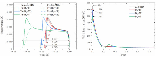
Figure 6.
Temperatures (left) and wall heat fluxes (right) on axis at different magnetic fields.
5.2. Jet Characteristics and Aerodynamic Performances with the Opposing Jet Combined with MHD Control Technology
5.2.1. Jet Characteristics
Considering the oscillation characteristics of the opposing jet, the time-accurate thermochemical nonequilibrium N-S equations were applied. The total flow time was set to 0.03 s, which was approximately 115 times the characteristic time and was sufficient to predict the jet characteristics and transient oscillation. To improve the calculation efficiency, chemical reactions were not considered before 0.02 s. However, the calculation requires a period to converge after adding chemical reactions; thus, this study only analyzed the data during 0.023–0.03 s. PR2.53 and PR5.07 jet conditions were employed, which correspond to a LPM jet and SPM jet, respectively, as shown in our previous studies. Four magnetic fields were adopted, including no-MHD, B0 = 1 T, B0 = 2 T, and B0 = 4 T.
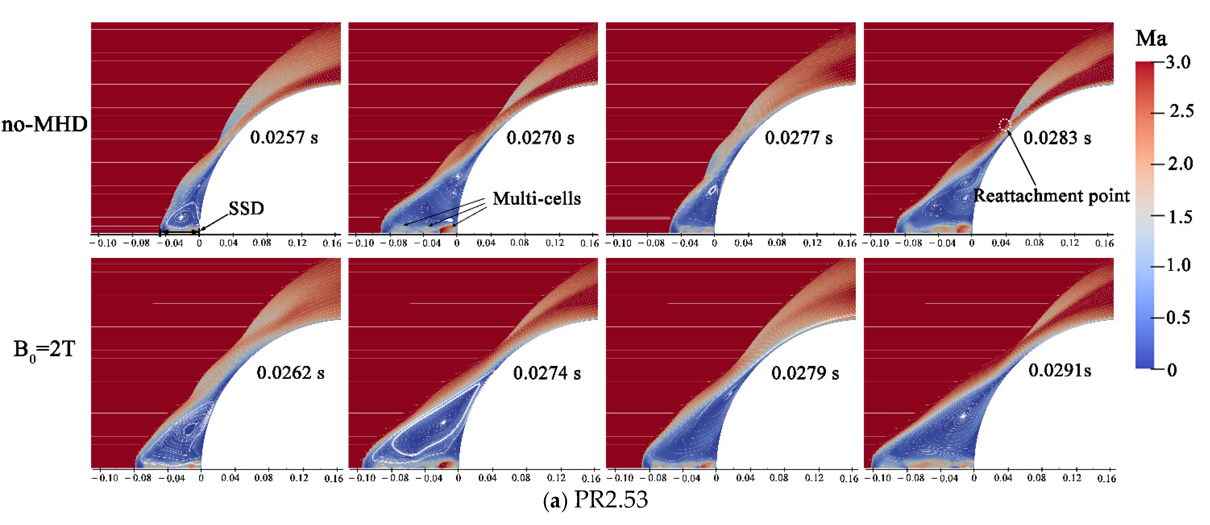
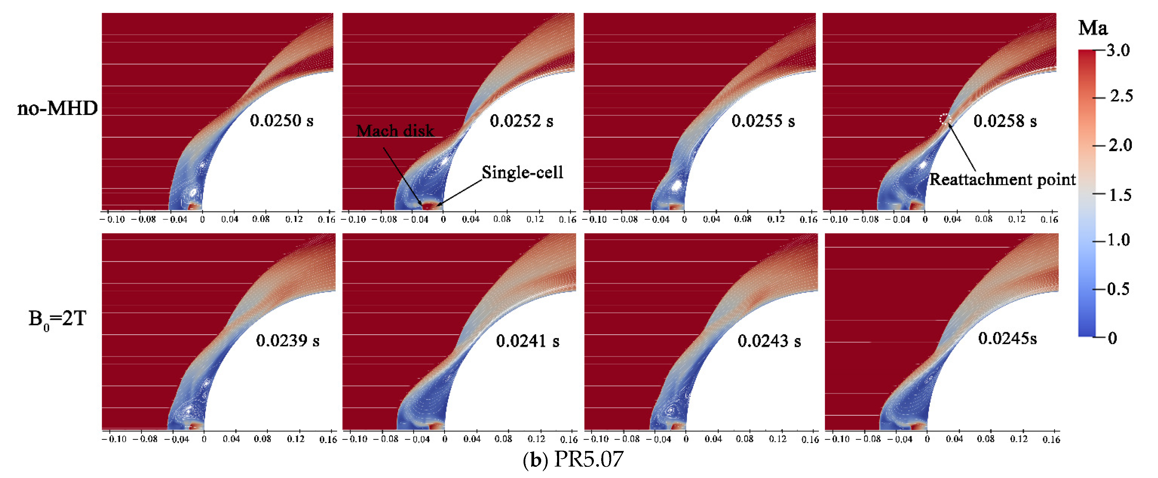
Figure 7a,b shows the Mach numbers of opposing jets combined with no-MHD and B0 = 2 T at different times under the PR2.53 and PR5.07 jet conditions, respectively. The Mach numbers of the two oscillation periods are displayed, and the corresponding extraction times are shown in Figure 8. As described in previous studies [6,20] of LPM and SPM, the jet mode under the PR2.53 jet conditions is LPM, where the jet behaves as a slender cylindrical shape with multiple expansion and compression jet cells. The jet mode under the PR5.07 jet condition is SPM, where the jet is a barrel shape with an expansion jet cell and is accompanied by a Mach disk.
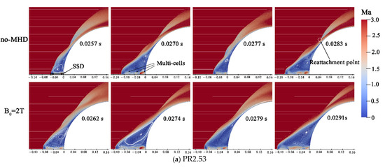
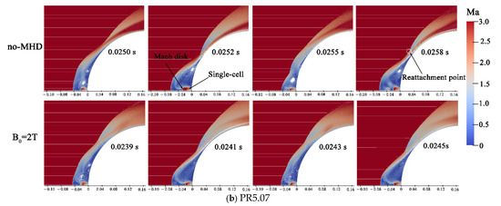
Figure 7.
Mach numbers of opposing jets combined without and with B0 = 2 T magnetic field.
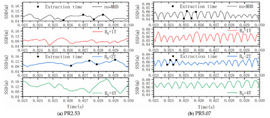
Figure 8.
SSDs of opposing jet combined different magnetic fields.
After introducing a magnetic field, the jet mode of PR2.53 is still LPM, whereas that of PR5.07 is still SPM, indicating that the jet mode is not affected by the dipole magnetic field. However, the jet structures were apparently changed after the introduction of a magnetic field under the PR2.53 and PR5.07 jet conditions. The SSD increased after the introduction of a magnetic field for both jet regimes. Additionally, the distance between the reattachment shock and the vehicle surface also increased. This demonstrates that the introduction of a magnetic field can change the shock structure, thereby further guiding the flow of the opposing jet and contributing to improving its thermal protection effect.
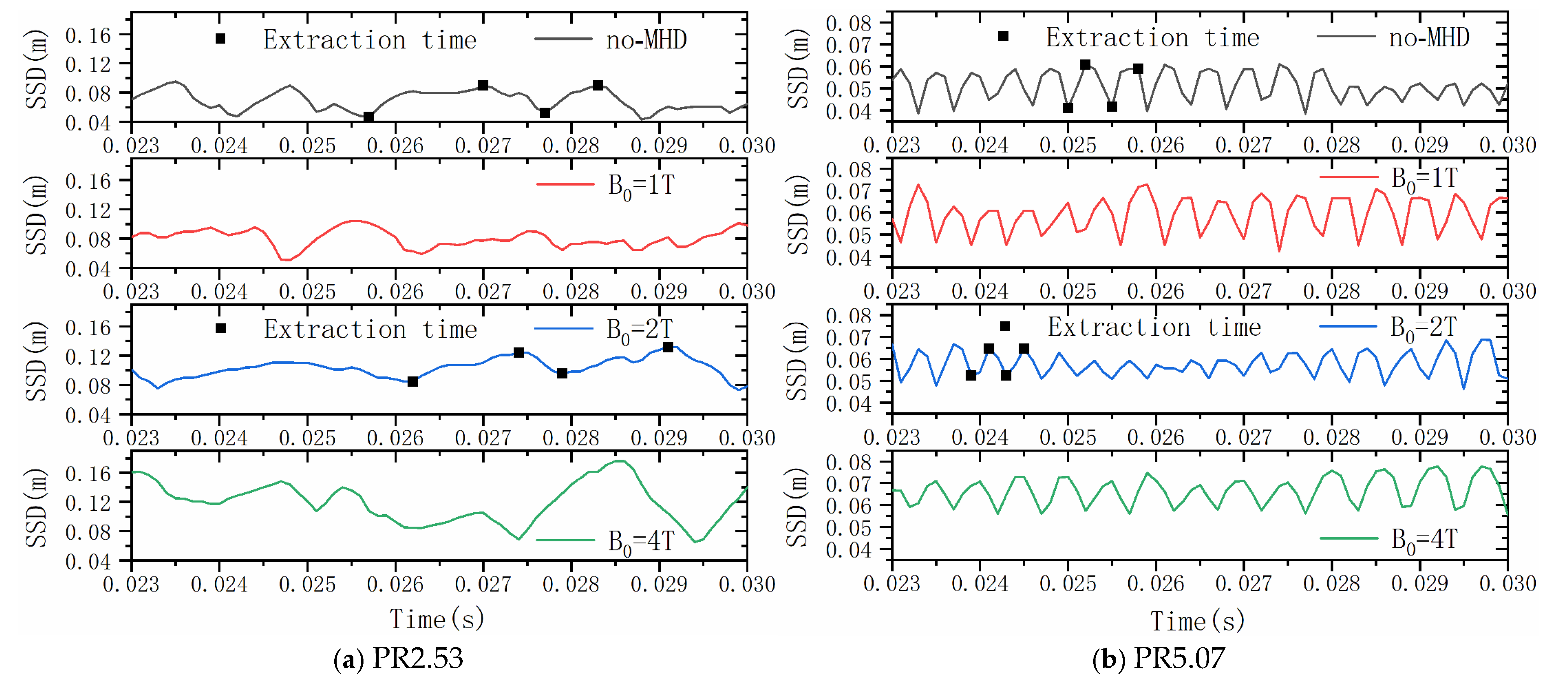
Figure 8a,b shows the SSDs during 0.023–0.03 s of the opposing jet combined with different magnetic fields under PR2.53 and PR5.07 jet conditions, respectively. As shown in the no-MHD condition of PR2.53 and PR5.07, it can be seen that the opposing jet exhibits periodic oscillations, and the oscillation frequency of the LPM jet is significantly lower than that of the SPM jet. In addition, the oscillation amplitude of the LPM jet is much bigger than that of the SPM jet. Deng’s studies [20] also reached the same conclusion; the difference is that the drag coefficient was employed in Deng’s studies. However, the SSD adopted in this paper more intuitively reflects the oscillation characteristics of opposing jet.
As shown in the B0 = 1 T, 2 T, and 4 T conditions, the SSD increased with increasing magnetic field strength under both jet conditions. Moreover, it can be seen that the introduction of a magnetic field affects the SSD oscillation amplitude. However, the influence of the magnetic field on the SSD oscillation amplitude is also affected by jet conditions. The oscillation amplitude of SSD in the PR2.53 apparently increased with increasing magnetic field strength, whereas that in PR5.07 showed no notable change. Based on the analysis of the jet flow state, it can be inferred that the influence of the magnetic field on the oscillation amplitude of the LPM jet is more significant compared to that of the SPM jet.
5.2.2. Aerodynamic Heat
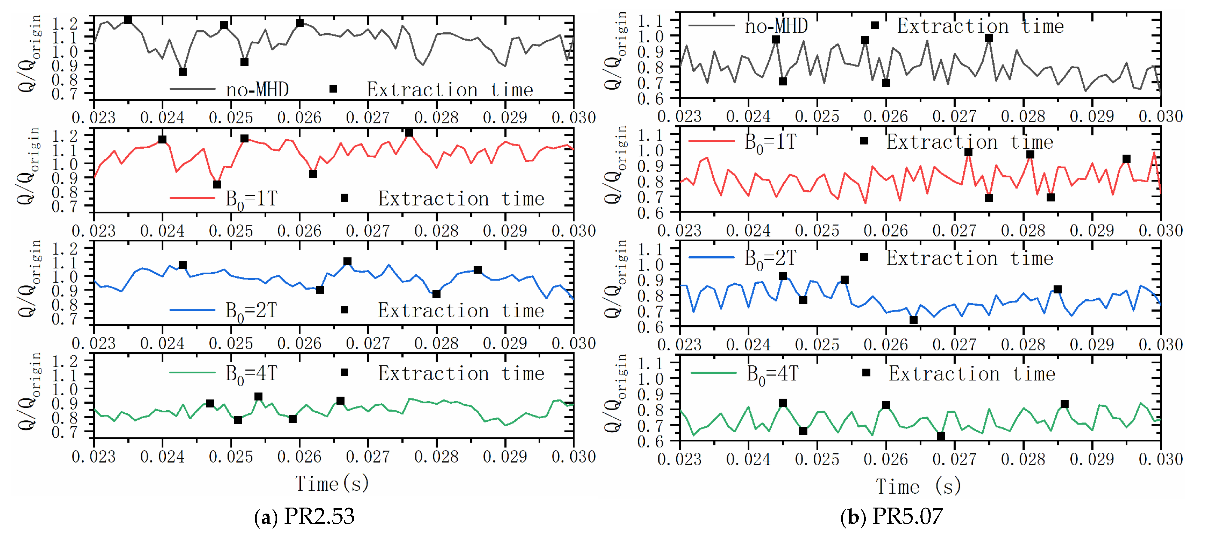
The aerodynamic heat ratio Q/Qorigin was used to quantify the overall thermal protection effectiveness, where Q is the total aerodynamic heat on the surface with the opposing jet combined with MHD control technology, and Qorigin is the total aerodynamic heat of the original surface without any thermal protection method.
Figure 9a,b shows Q/Qorigin of the opposing jet combined with no-MHD and B0 = 1 T, 2 T, and 4 T magnetic fields under PR2.53 and PR5.07 jet conditions, respectively. The values of Q/Qorigin > 1 in the no-MHD condition at PR2.53 indicate that the opposing jet not only fails to provide thermal protection but also further aggravates the aerodynamic heating environment around the vehicle. This verifies the conclusion from the experiments [6] that the LPM jet cannot provide effective thermal protection. In the PR5.07 jet condition, Q/Qorigin < 1 in the no-MHD condition, which confirms the experimental conclusion [5,6] that the SPM jet can provide effective thermal protection.

Figure 9.
Aerodynamic heat ratios of opposing jet combined with different magnetic fields.
In the two jet conditions, the Q/Q origin of the B0 = 1 T, 2 T, and 4 T conditions is smaller than that of the no-MHD condition, indicating that the introduction of a magnetic field can indeed improve the thermal protection ability of the opposing jet. Q/Qorigin decreases as the magnetic field strength increases, indicating that the thermal protection effect of the opposing jet combined with MHD control technology can be improved by increasing the magnetic field strength.
As discussed in previous studies [5], the opposing jet can reduce the heat flux in the head of the vehicle by ejecting the cooling medium. However, the reattachment shock of the LPM jet aggravates the aerodynamic heat in the shoulder region of the vehicle, where the local heat flux is even larger than that in the vehicle head without an opposing jet. Undoubtedly, the peak heat flux is crucial for the selection of vehicle surface materials. Therefore, it is necessary to discuss the distribution of wall heat flux to further explore the local thermal protection effect of the opposing jet combined with MHD control technology.
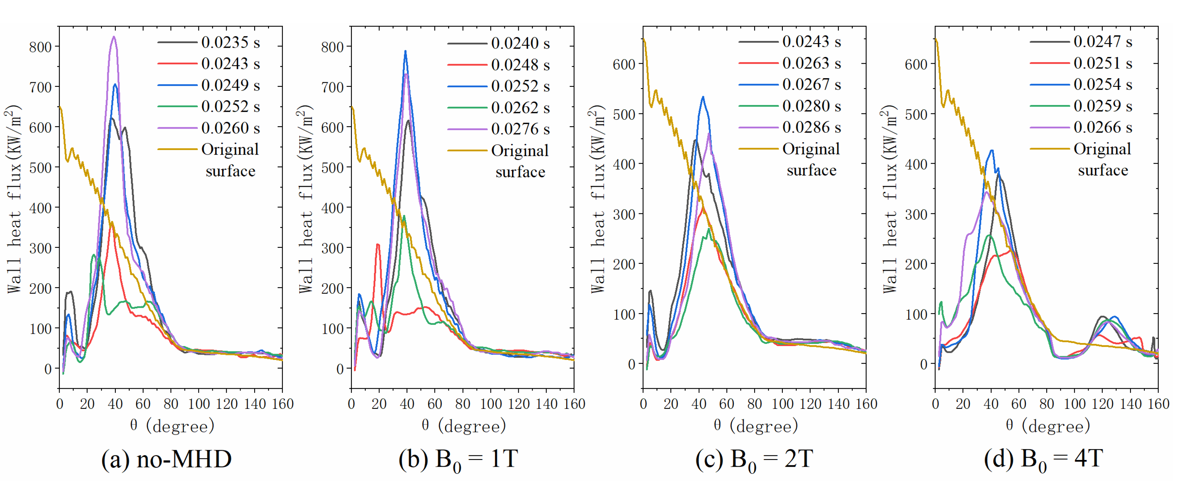
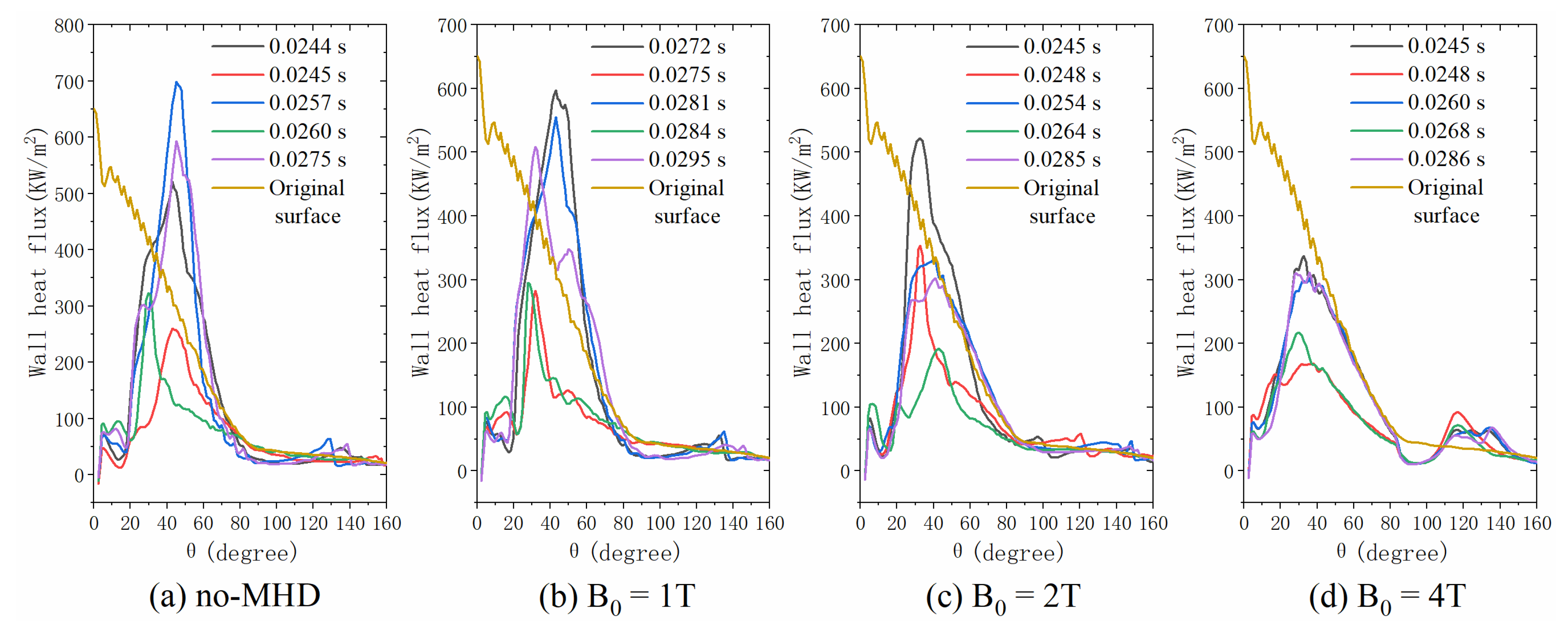
Figure 10 and Figure 11 show the distributions of wall heat flux during two oscillation periods under PR2.53 and PR5.07 jet conditions, respectively. The extraction time points of the wall heat flux are shown in Figure 9, referring to five moments that include three maximum and two minimum total heat fluxes. As shown in Figure 10 and Figure 11, it can be seen that the oscillatory characteristics of the opposing jet result in a risk of transient thermal shock to the vehicle. However, the introduction of MHD technology mitigated this risk, and the degree of this risk decreases as the magnetic field strength increases.
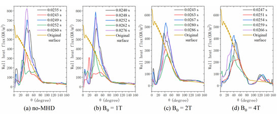
Figure 10.
Wall heat fluxes of opposing jet combined with different magnetic fields under PR2.53 jet condition.
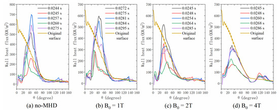
Figure 11.
Wall heat fluxes of opposing jet combined with different magnetic fields under PR5.07 jet condition.
As shown in Figure 10a,b and Figure 11a, the peak values of wall heat flux at some moments are bigger than that of the original surface, indicating that under PR2.53 and PR5.07 opposing jets, and the PR2.53 opposing jet combined with the B0 = 1 T magnetic field cannot provide effective thermal protection at some moments. However, the jet mode in the PR5.07 jet condition is SPM. Therefore, this conclusion is different from the conclusions of previous studies [7,8] which state that SPM jets can provide absolute thermal protection. The fundamental reason for this is that the SPM jet in this study exhibits strong instability, while those in previous studies present a steady state. However, the flight environments of the vehicle are different between this and previous studies. The gas environment at a high altitude is more rarefied than at a low altitude, which results in the opposing jet exhibiting an obvious oscillation.
As shown in Figure 10b–d and 11b–d, the introduction of a magnetic field apparently reduces the peak wall heat flux in PR2.53 and PR5.07 jet conditions. The results also show that the peak wall heat flux decreases sequentially at B0 = 1 T, 2 T, and 4 T, indicating that a larger magnetic field strength is beneficial for improving the thermal protection effect.
5.2.3. Aerodynamic Drag
The fundamental reason that the magnetic field can push the freestream shock away from the surface is the introduction of Lorentz force. According to Newton’s Third Law, the Lorentz force also acts on the vehicle and becomes part of the aerodynamic drag [42]. Therefore, the total drag FD can be decomposed into two components: the drag caused by pressure and viscous stress FS (shock drag) and the reaction force of the Lorentz force FL (Lorentz drag), as shown in Equation (11).
An axisymmetric model was applied in this study; thus, the shock drag FS was the surface integral of the axial components of pressure and viscous stress. The Lorentz drag FL is the volume integral of the axial component of the reaction of the Lorentz force, which is written as
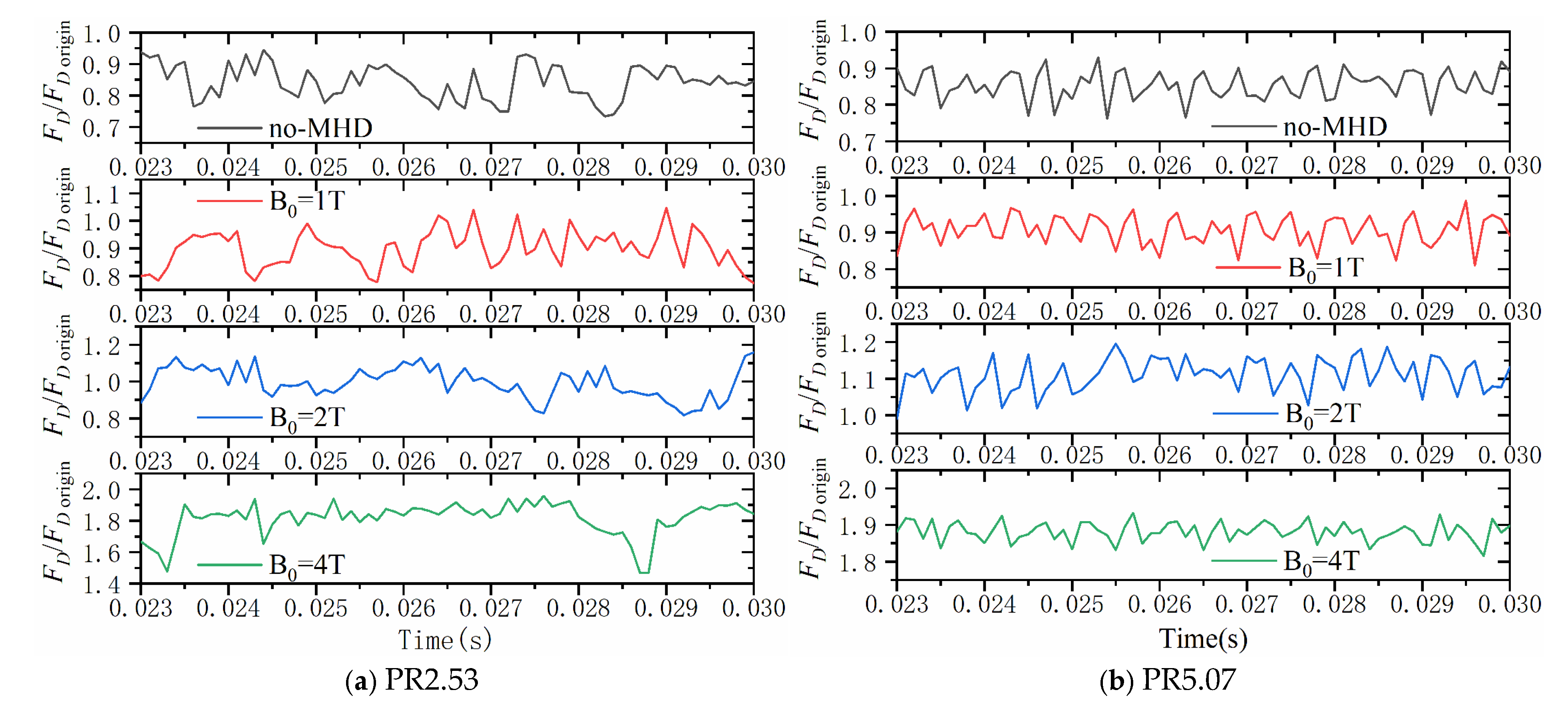
Figure 12a,b shows the total drag ratios (FD/FDorigin) under the PR2.53 and PR5.07 jet conditions during 0.023–0.03 s, where FDorigin denotes the aerodynamic drag of the ELECTRE vehicle without any thermal protection technology. The total drag ratios FD/FDorigin of the no-MHD condition in the two jet conditions are less than 1, indicating that both LPM and SPM opposing jets can reduce the drag, which is consistent with Kim’s study [43]. The aerodynamic drag of the vehicle equipped with the opposing jet combined with MHD control technology is affected by the magnetic field strength. It can be seen that the higher the magnetic field strength, the greater the aerodynamic drag.
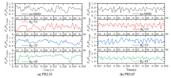
Figure 12.
Total drag ratios of opposing jet combined with different magnetic fields.
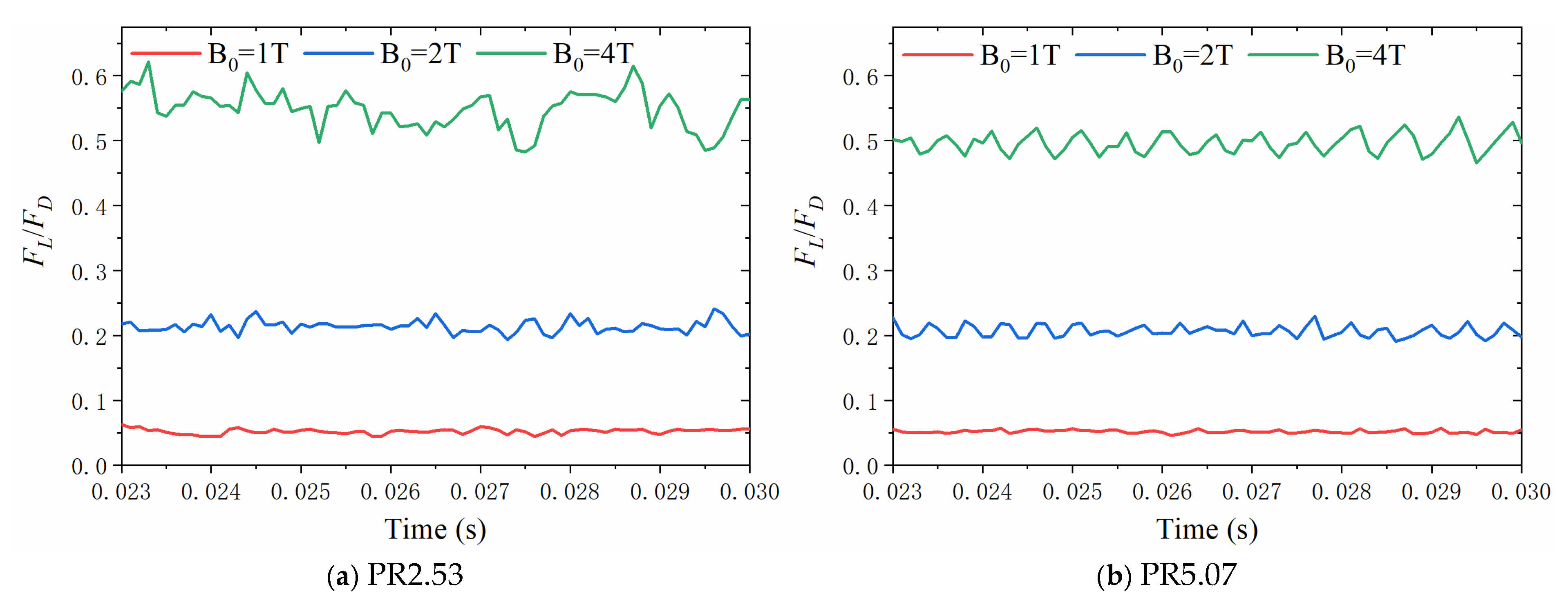
To explain the influence of the Lorentz drag on the total drag, Figure 13a,b shows the ratio of Lorentz drag to the total drag FL/FD under PR2.53 and PR5.07 jet conditions with different magnetic fields. Under the two jet conditions, the values of FL/FD increased as the magnetic field strength increased. At B0 = 4 T, the values of FL/FD under the two jet conditions are greater than 0.5, indicating that the Lorentz drag accounts for most of the aerodynamic drag when the magnetic field strength is greater than a critical value. The FL/FD is also affected by the jet condition, and it can be seen that the FL/FD under PR2.53 jet is bigger than that under PR5.07 jet at the same magnetic field. This is because different jet mass flow rates result in different shock structures which determine the shock drag. Furthermore, the shock structure affects the distribution of the Lorentz force, resulting in different Lorentz drag values at different jet mass flow rates.
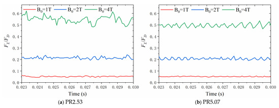
Figure 13.
Ratio of the Lorentz drag to the total drag of the opposing jet combined with different magnetic fields.
5.3. Comprehensive Evaluation of the Aerodynamic Performances
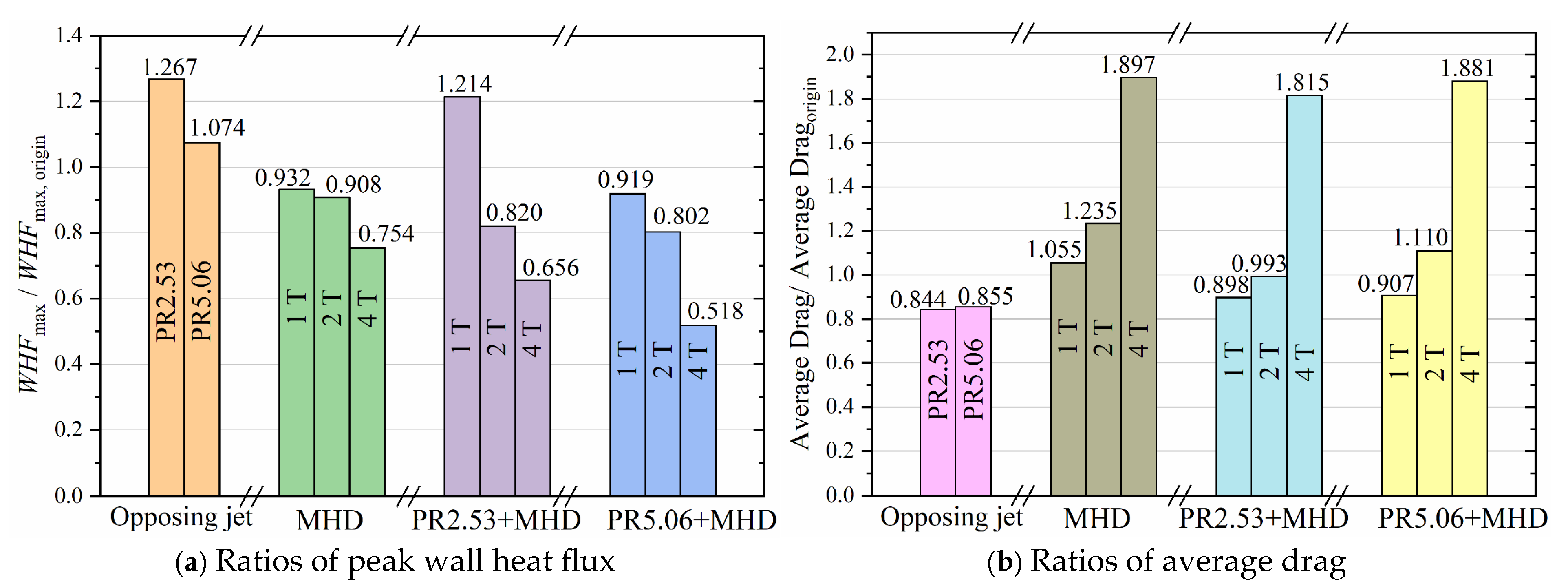
To further comprehensively investigate the aerodynamic performances of the opposing jet combined with MHD control technology, Figure 14a,b, respectively, presents the ratios of peak wall heat flux and average drag with different technologies, including opposing jet, MHD control, and opposing jet combined with MHD control. The WHFmax,origin denotes the peak wall flux of the original surface of ELECTRE vehicle without any thermal protection technology, and the Average Dragorigin represents the average drag of original vehicle during 0.023–0.03 s.
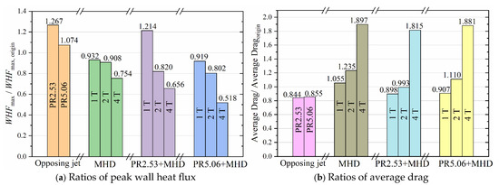
Figure 14.
Ratios of peak wall heat flux and average drag of different technologies.
Under B0 = 2 T and 4 T magnetic fields, the ratios of the peak wall heat flux of the opposing jet combined with MHD control technology are lower than those of the opposing jet technology and the MHD control technology alone, indicating that the opposing jet combined with MHD control technology can provide a better thermal protection effect for vehicles compared with the opposing jet technology and the MHD control technology alone. Based on the jet mode of PR2.53 jet, it can be inferred that the magnetic field of B0 = 2 T enables the LPM jet to own thermal protection capability. This indicates that, if a suitable magnetic field is provided, even the opposing jet with a low mass flow rate can provide an excellent thermal protection for hypersonic vehicles.
The average drag with the opposing jet combined with MHD control technology is much lower than that with MHD control technology alone. This is due to the fact that the opposing jet reduces the drag, despite the introduction of the magnetic field increasing the aerodynamic drag. Therefore, the total drag does not increase under a low magnetic field, such as B0 = 1 T, where the Lorentz drag can be neglected. It is noteworthy that under the B0 = 2 T magnetic field condition, the average drag of vehicle with PR2.53 opposing jet combined with MHD control technology is even slightly lower than the original drag of vehicle without any thermal protection technology. This is mainly attributed to the superior drag reduction capability of the LPM jet. Therefore, the opposing jet combined with MHD technology is able to address, to some extent, the issue of increased drag caused by the introduction of magnetic fields.
In short, the opposing jet combined with MHD control technology not only provides a better thermal protection effect than the MHD control and opposing jet technologies but also has a lower aerodynamic drag than the MHD control technology, which is conducive to the long-term flight of hypersonic vehicles.
6. Conclusions
Taking the ELECTRE vehicle as the research object, we investigated the jet characteristics, thermal protection effect, and aerodynamic drag characteristics of a novel thermal protection method, which is the opposing jet combined with MHD control technology. Referring to the flight conditions of the ELECTRE vehicle (53.3 km with a velocity of 4230 m/s) and the transient characteristics of the opposing jet, the time-accurate nonequilibrium N-S equations coupled with a low-magnetic-Reynolds-number model were applied. Two jet modes (PR2.53 with LPM, PR5.07 with SPM) and four magnetic fields (no-MHD, B0 = 1 T, B0 = 2 T, and B0 = 4 T) were employed in this study.
The comparisons of the jet characteristics of the opposing jet and the opposing jet combined with MHD control technologies show that the introduction of a magnetic field increased the SSD and pushed the reattachment shock away from the surface, indicating that the magnetic field can guide the opposing jet flow by controlling the shock structure. And the SSD increased as the strength of magnetic field increased. The dipole magnetic field did not affect the jet mode but had a certain impact on the instability of the opposing jet.
The introduction of a magnetic field enabled the LPM jet with a smaller jet mass flow to possess thermal protection capability, and the thermal protection effect increased with the enhancement of the strength of magnetic field. Compared to MHD control technology, this novel technology can offer better thermal protection. Under B0 = 2 T and 4 T magnetic fields, the ratios of peak wall heat flux for the MHD control technology are 0.908 and 0.754, respectively, whereas those for the PR2.53 jet combined with MHD control technology are 0.820 and 0.656, respectively. Furthermore, this technology offered lower aerodynamic drag compared to the MHD control technology. For instance, when the PR2.53 jet combined with the B0 = 2 T magnetic field, the ratio of average drag was merely 0.993, indicating that this technology can provide efficient thermal protection without increasing aerodynamic drag.
Author Contributions
Conceptualization, W.Z. and Z.Z.; Methodology, W.Z. and Z.Z.; Validation, W.Z. and Z.Z.; Investigation, W.Z.; Resources, W.Z. and Z.Z.; Data curation, W.Z. and W.G.; Writing—original draft preparation, W.Z.; Writing—review and editing, W.Z. and Z.Z.; Funding acquisition, Z.Z. and W.Z. All authors have read and agreed to the published version of the manuscript.
Funding
This research was funded by the National Natural Science Foundation of China (Grant nos.U20A20292); Key laboratory of hypersonic aerodynamic force and heat technology, AVIC Aerodynamics Research Institute; Advanced Space Propulsion Laboratory of BICE and Beijing Engineering Research Center of Efficient and Green Aerospace Propulsion Technology, No: LabASP-2020-02; Key Laboratory of Environmental Optics and Technology, Chinese Academy of Sciences (Grant No. 2005DP173065-2022-02).
Data Availability Statement
The original contributions presented in this study are included in the article. Further inquiries can be directed to the corresponding author.
Acknowledgments
The authors would like to thank Vincent Casseau for his constant support with Hy2Foam solver.
Conflicts of Interest
The authors declare that they have no conflicts of interest.
Abbreviations
| MHD | magnetohydrodynamic |
| LPM | long penetration mode |
| SPM | short penetration mode |
| SSDPR | shock standoff distancepressure ratio |
| Nomenclature | |
| J | electric current density vector |
| B | magnetic field vector |
| E | electric field vector |
| σ | electrical conductivity |
| reference electrical conductivity | |
| γ | ratio constant |
| ρs | density of species s |
| ui, uj | velocity vectors |
| p | pressure |
| E | total energy per unit volume |
| Eve | vibro-electronic energy per unit volume |
| eve,s | vibro-electronic energy per unit mass of species s |
| Js,j | mass diffusion flux |
| δij | Kronecker delta |
| τij | shear stress tensor |
| qj | total heat conduction vector |
| qve,j | vibro-electronic heat conduction vector |
| hs | enthalpy per unit mass of species s |
| chemical source term | |
| T0 | reference temperature |
| Ttr | trans-rotational temperature |
| n | constant |
| B0 | magnetic field strength of the reference point |
| r0 | distance between the reference point and the dipole magnet center |
| r | position vector |
| ǀrǀ | magnitude of the r |
| m | angle vector between the dipole magnet and the flow field axis |
References
- Qi, Y.; Ma, X.; Jiang, P.; Zhu, Y. Review on heat-to-power conversion technologies for hypersonic vehicles. Chin. J. Aeronaut. 2024, 37, 148–179. [Google Scholar] [CrossRef]
- van Heerden, A.S.J.; Judt, D.M.; Jafari, S.; Lawson, C.P.; Nikolaidis, T.; Bosak, D. Aircraft thermal management: Practices, technology, system architectures, future challenges, and opportunities. Prog. Aerosp. Sci. 2022, 128, 100767. [Google Scholar]
- Zhang, S.; Li, X.; Zuo, J.; Qin, J.; Cheng, K.; Feng, Y.; Bao, W. Research progress on active thermal protection for hypersonic vehicles. Prog. Aerosp. Sci. 2020, 119, 100646. [Google Scholar]
- Liu, S.; Yan, C.; Kang, D.; Jiang, Z.; Sun, M. Opposing jets for heat flux reduction and uncertainty analysis on a V-shaped blunt leading edge. Aerosp. Sci. Technol. 2023, 138, 108353. [Google Scholar] [CrossRef]
- Hayashi, K.; Aso, S.; Tani, Y. Experimental Study on Thermal Protection System by Opposing Jet in Supersonic Flow. J. Spacecr. Rocket. 2006, 43, 233–235. [Google Scholar]
- Daso, E.O.; Pritchett, V.E.; Wang, T.S.; Ota, D.K.; Blankson, I.M.; Auslender, A.H. Dynamics of Shock Dispersion and Interactions in Supersonic Freestreams with Counterflowing Jets. AIAA J. 2009, 47, 1313–1326. [Google Scholar]
- Huang, W.; Zhang, R.R.; Yan, L.; Ou, M.; Moradi, R. Numerical experiment on the flow field properties of a blunted body with a counterflowing jet in supersonic flows. Acta Astronaut. 2018, 147, 231–240. [Google Scholar]
- Bibi, A.; Maqsood, A.; Sherbaz, S.; Dala, L. Drag reduction of supersonic blunt bodies using opposing jet and nozzle geometric variations. Aerosp. Sci. Technol. 2017, 69, 244–256. [Google Scholar] [CrossRef]
- Sriram, R.; Jagadeesh, G. Film cooling at hypersonic Mach numbers using forward facing array of micro-jets. Int. J. Heat Mass Transf. 2009, 52, 3654–3664. [Google Scholar]
- Ji, C.; Liu, B.; Huang, W.; Li, S.; Meng, Z.; Yan, L.; Choubey, G. Design exploration on the drag reduction and thermal protection over a blunted waverider with multiple opposing jets. Aerosp. Sci. Technol. 2022, 124, 107519. [Google Scholar] [CrossRef]
- Zhang, W.; Wang, X.; Zhang, Z.; Han, F.; Zhao, S. Heat and drag reduction of single and combined opposing jets in hypersonic nonequilibrium flows. Aerosp. Sci. Technol. 2022, 121, 107194. [Google Scholar]
- Eghlima, Z.; Mansour, K.; Fardipour, K. Heat transfer reduction using combination of spike and counterflow jet on blunt body at high Mach number flow. Acta Astronaut. 2018, 143, 92–104. [Google Scholar]
- Huang, J.; Yao, W.; Shan, X. Coupled fluid-thermal investigation on non-ablative thermal protection system with spiked body and opposing jet combined configuration. Chin. J. Aeronaut. 2019, 32, 1390–1402. [Google Scholar]
- Vali, S.E.; Abbasi, S. Hypersonic drag and heat reduction mechanism of a new hybrid method of spike, multi-row discs and opposing jets aerodynamic configuration. Int. J. Heat Mass Transf. 2022, 194, 123034. [Google Scholar]
- Wang, Z.; Zhang, X. Research on a novel combined shock control mechanism for thermal protection and drag reduction in hypersonic compressible flow field. Int. J. Heat Mass Transf. 2023, 201, 123592. [Google Scholar]
- Huang, W.; Yan, L.; Liu, J.; Jin, L.; Tan, J. Drag and heat reduction mechanism in the combinational opposing jet and acoustic cavity concept for hypersonic vehicles. Aerosp. Sci. Technol. 2015, 42, 407–414. [Google Scholar]
- Zhang, R.; Dong, M.; Huang, W.; Li, S.; Du, Z.; Liao, J. Drag and heat flux reduction mechanism induced by the combinational forward-facing cavity and pulsed counterflowing jet configuration in supersonic flows. Acta Astronaut. 2019, 160, 62–75. [Google Scholar]
- Sudarshan, B.; Rao, S.M.V.; Jagadeesh, G.; Saravanan, S. Effect of the axial cavity with an opposing high-pressure jet combination in a Mach 6 flow condition. Acta Astronaut. 2021, 178, 335–348. [Google Scholar]
- Fujita, M. Axisymmetric oscillations of an opposing jet from a hemispherical nose. In Proceedings of the 32nd Aerospace Science Meeting & Exhibit, Reno, NV, USA, 10–13 January 1994. [Google Scholar]
- Deng, F.; Xie, F.; Huang, W.; Dong, H.; Zhang, D. Numerical exploration on jet oscillation mechanism of counterflowing jet ahead of a hypersonic lifting-body vehicle. Sci. China Technol. Sci. 2018, 61, 1056–1071. [Google Scholar] [CrossRef]
- Kim, Y.; Roh, T.-S.; Lee, H.J. Mechanism and prediction of flow oscillation based on counter-flow jet for drag reduction in hypersonic flow. Aerosp. Sci. Technol. 2022, 126, 107603. [Google Scholar] [CrossRef]
- Zhang, W.; Wang, X.; Zhang, Z.; Su, T. Numerical Investigation on the Jet Characteristics and the Heat and Drag Reductions of Opposing Jet in Hypersonic Nonequilibrium Flows. Aerospace 2022, 9, 554. [Google Scholar] [CrossRef]
- Zhao, K.; Ming, M.; Li, F.; Lu, Y.; Zhou, T.; Wang, K.; Meng, N. Experimental study on plasma jet deflection and energy extraction with MHD control. Chin. J. Aeronaut. 2020, 33, 1602–1610. [Google Scholar]
- Schramm, J.M.; Hannemann, K. Study of MHD Effects in the High-Enthalpy Shock Tunnel Göttingen (HEG) Using a 30 T-Pulsed Magnet System. In Proceedings of the 31st International Symposium on Shock Waves, Nagoya, Japan, 9–14 July 2017. [Google Scholar]
- Ziemer, R.W.; Bush, W.B. Magnetic Field Effects on Bow Shock Stand-Off Distance. Phys. Rev. Lett. 1958, 1, 58–59. [Google Scholar]
- Smith, D.R.; Gildfind, D.E.; Jacobs, P.A.; Cullen, T.G.; Mcintyre, T.J. Magnetohydrodynamic Drag Measurements in an Expansion Tunnel with Argon Test Gas. AIAA J. 2020, 58, 4495–4504. [Google Scholar]
- Smith, D.R.; Gildfind, D.E.; James, C.M.; Mcintyre, T.J.; Wheatley, V. Magnetohydrodynamic drag force measurements in an expansion tube. In Proceedings of the 2018 Flow Control Conference, Atlanta, GA, USA, 25–29 June 2018. [Google Scholar]
- Gong, G.; Li, Y.W.; Wang, Y.T.; Kuang, P. Investigation on wedge shock wave control by surface MHD actuation. AIP Adv. 2020, 10, 005212. [Google Scholar]
- Jiang, H.; Liu, J.; Che, X.; Du, Y.; Huang, W.; Ding, F.; Zhang, T. Magnetic field control of high-enthalpy shock wave/boundary-layer interactions using a fully implicit thermochemical non-equilibrium solver. Aerosp. Sci. Technol. 2023, 141, 108507. [Google Scholar]
- Luo, S.; Wu, L.; Chang, Y.; Li, X. Thermochemical non-equilibrium and electromagnetic effects of double-cone in hypervelocity flow. Aerosp. Sci. Technol. 2023, 132, 108041. [Google Scholar]
- Wang, D.; Wang, J.; Li, L. Electromagnetic field/hypersonic flow field coupled algorithm and its application in the magnetic controlled inlet design. Aerosp. Sci. Technol. 2022, 126, 107598. [Google Scholar]
- Park, C. Assessment of two-temperature kinetic model for dissociating and weakly-ionizing nitrogen. J. Thermophys. Heat Transf. 1987, 2, 8–16. [Google Scholar]
- Muir, H.A.; Nikiforakis, N. Numerical modeling of imposed magnetohydrodynamic effects in hypersonic flows. Phys. Fluids 2022, 34, 107114. [Google Scholar]
- Zhang, W.; Zhang, Z.; Wang, X.; Su, T. A review of the mathematical modeling of equilibrium and nonequilibrium hypersonic flows. Adv. Aerodyn. 2022, 4, 38. [Google Scholar]
- Bisek, N.J.; Boyd, I.D.; Poggie, J. Numerical Study of Electromagnetic Aerodynamic Control of Hypersonic Vehicles. In Proceedings of the 47th AIAA Aerospace Sciences Meeting Including the New Horizons Forum and Aerospace Exposition, Orlando, FL, USA, 5–8 January 2009. [Google Scholar]
- Otsu, H.; Konigorski, D.; Abe, T. Influence of Hall Effect on Electrodynamic Heat Shield System for Reentry Vehicles. AIAA J. 2010, 48, 2177–2186. [Google Scholar]
- Nagata, Y.; Otsu, H.; Yamada, K.; Abe, T. Influence of Hall Effect on Electrodynamic Flow Control for Weakly Ionized Flow. In Proceedings of the 43rd AIAA Plasmadynamics and Lasers Conference, New Orleans, LA, USA, 25–28 June 2012. [Google Scholar]
- Fujino, T.; Matsumoto, Y.; Kasahara, J.; Ishikawa, M. Numerical Studies of Magnetohydrodynamic Flow Control Considering Real Wall Electrical Conductivity. J. Spacecr. Rocket. 2007, 44, 625–632. [Google Scholar]
- Casseau, V. An Open-Source CFD Solver for Planetary Entry. Ph.D. Thesis, University of Strathclyde, Glasgow, Scotland, 2017. [Google Scholar]
- Ding, M.S.; Jiang, T.; Liu, Q.Z.; Dong, W.Z.; Gao, T.S.; Fuyang, A.Y. Impact of simulation of electrical conductivity on hypersonic MHD control. Acta Aeronaut. Astronaut. Sin. 2019, 40, 123009. (In Chinese) [Google Scholar]
- Muylaert, J.; Walpot, L.; Haeuser, J.; Sagnier, P.; Devezeaux, D.; Papirnyk, O.; Lourme, D. Standard model testing in the European High Enthalpy Facility F4 andextrapolation to flight. In Proceedings of the AIAA 17th Aerospace Ground Testing Conference, Nashville, TN, USA, 6–8 July 1992. [Google Scholar]
- Smith, D.R.; Gildfnd, D.E.; McIntyre, T.J.; Mee, D.J.; James, C.M.; Andrianatos, A. Magnetohydrodynamic drag force measurements in expansion tunnels using an accelerometer-based force balance. Exp. Fluids 2019, 60, 183. [Google Scholar]
- Kim, Y.; Roh, T.-S.; Huh, H.; Lee, H.J. Study on the combined effect of various injection conditions on the drag reduction by a counter-flow jet in supersonic flow. Aerosp. Sci. Technol. 2020, 98, 105580. [Google Scholar]
Disclaimer/Publisher’s Note: The statements, opinions and data contained in all publications are solely those of the individual author(s) and contributor(s) and not of MDPI and/or the editor(s). MDPI and/or the editor(s) disclaim responsibility for any injury to people or property resulting from any ideas, methods, instructions or products referred to in the content. |
© 2025 by the authors. Licensee MDPI, Basel, Switzerland. This article is an open access article distributed under the terms and conditions of the Creative Commons Attribution (CC BY) license (https://creativecommons.org/licenses/by/4.0/).