Article

Adaptive UAV Control with Sensor and Actuator Faults Recovery

1
LAGE Laboratory, Kasdi Merbah University, Ouargla 30000, Algeria
2
Centre for Aeronautics, Cranfield University, College Road, Cranfield MK43 0AL, UK
3
School of Engineering, University of Leicester, University Road, Leicester LE1 7RH, UK
*
Author to whom correspondence should be addressed.
Aerospace 2025, 12(3), 261; https://doi.org/10.3390/aerospace12030261
Submission received: 19 December 2024 / Revised: 7 March 2025 / Accepted: 15 March 2025 / Published: 19 March 2025
(This article belongs to the Special Issue Challenges and Innovations in Aircraft Flight Control)

Abstract

:
This paper presents an adaptive fault-tolerant control strategy tailored for fixed-wing unmanned aerial vehicles (UAV) operating under adverse conditions such as icing. Using radial basis function neural networks and nonlinear dynamic inversion, the proposed framework effectively handles simultaneous actuator and sensor faults with arbitrary nonlinear dynamics caused by environmental effects, model uncertainties and external disturbances. A nonlinear disturbance observer is incorporated for accurate sensor fault detection and estimation, thereby enhancing the robustness of the control system. The integration of the radial basis function neural network enables an adaptive estimation of the faults, ensuring accurate fault compensation and system stability under challenging conditions. The observer is optimised to minimise the deviation of the closed-loop dynamics eigenvalues from the assigned eigenvalues and to approach unity observer steady-state gain. The stability of the control architecture is mathematically proven using Lyapunov analysis, and the performance of the approach is validated through numerical simulations on a six Degrees of Freedom fixed-wing unmanned aerial vehicles model. The results show superior performance and robustness to challenging fault scenarios. This research provides a comprehensive fault management solution that enhances the safety and reliability of unmanned aircraft operations in extreme environments.

1. Introduction

Unmanned aerial vehicles (UAV) have become indispensable tools in various sectors, offering numerous benefits that improve efficiency and safety in a wide range of applications. In agriculture, UAVs are essential for crop monitoring and precision farming, providing real-time data to optimise yields and reduce costs [1]. In search and rescue missions, UAVs can quickly survey large areas, providing vital information to rescuers in remote or hard-to-reach locations [2]. They are also used extensively for infrastructure inspections, such as power lines, bridges and pipelines, enabling safe and efficient data collection without putting human workers at risk [3]. In addition, UAVs play an important role in environmental monitoring, helping to track wildlife, assess pollution and assess damage from natural disasters [4]. These diverse applications demonstrate how UAVs are transforming industries by increasing capabilities, improving efficiency and enhancing safety. As a result, ensuring the safe and reliable operation of UAVs has become a key area of research [5].
However, UAVs are susceptible to faults in actuators and sensors that can affect mission performance [6]. Common causes of these faults or failures include mechanical wear, exposure to harsh environments like icing conditions, electrical problems, aerodynamic pressures, vibrations and manufacturing or assembly errors. This has led to the development of fault-tolerant control systems that enable UAVs to maintain effective operation even when faults occur [7].
The simultaneous fault of actuators and sensors in fixed-wing UAVs presents a complex challenge to aerospace engineering [8]. Actuators carry out control commands, while sensors collect essential data on the UAV’s attitude and speed. If both systems fail at the same time, the UAVs performance can be severely degraded or lost altogether; for example, speed sensor faults coupled with actuator problems in icing conditions can result in inaccurate data that can compromise the UAV’s stability [9].
Over the past two decades, considerable research has been devoted to solving the challenges of fault-tolerant control (FTC) for UAVs, resulting in a wide range of techniques and approaches. These include adaptive control [10,11], model predictive control [12,13], optimal control [14,15], sliding mode control [16,17,18], nonlinear dynamic inversion (NDI) control [19], backstepping control [20], fuzzy logic-based robust control [21,22] and neural network-based control [23]. Each of these methods offers unique advantages in maintaining system reliability and functionality even when faults occur.
Several methods have been developed for fault-tolerant control of UAVs, including adaptive control approaches [7,10] and robust methods combining adaptive control and nonlinear dynamic inversion strategies [24]. In [25], the author proposes a fault-tolerant control for fixed-wing UAVs using a sliding mode disturbance observer and adaptive dynamic inversion. The outer loop suppresses disturbances with a super-twisting algorithm, while the inner loop adapts to control surface failures using real-time aerodynamic identification. In [26], the author studies electric aircraft under damage conditions and designs an L1 adaptive fault-tolerant control law, showing strong robustness and safety improvements. In [27], the paper proposes an adaptive dynamic inverse control method to counteract icing effects on aircraft. Using a control allocation algorithm, it ensures robustness, fault tolerance and accurate tracking, improving flight safety and performance in icing conditions. Radial basis function (RBF) neural networks and adaptive controllers have also been used for their real-time adaptability and robustness [28,29]. Further details can be found in the review paper [6], where recent approaches to the recovery from UAV sensor and actuator faults are described. Nonlinear disturbance observers (NDO) are among the most effective methods for detecting and compensating for sensor faults [7] and play a key role in fault-tolerant control systems. The core concept of a disturbance observer is to consolidate internal uncertainties, external disturbances, parameter variations and unmodelled dynamics into a single lumped disturbance [25,30]. Nonlinear disturbance observers have also been used to develop fault-tolerant control systems [31].
Building on previous literature, this research addresses the critical but under-researched challenge of simultaneously managing actuator and sensor faults induced by adverse weather conditions, such as icing, in fixed-wing UAVs [9]. For the control design, actuator and sensor faults are typically considered separately [32,33] with few exceptions as in [34]. This study addresses the recovery from both faults simultaneously, providing a more holistic and integrated solution. Unlike previous work that relies on simplified models [11], this study uses a six Degrees Of Freedom (6DoF) nonlinear model for fixed-wing, providing a more accurate representation of their dynamic behaviour. The proposed approach combines an adaptive fault-tolerant controller using radial basis function neural networks, known for their effectiveness in handling nonlinearities and uncertainties [28,29], with a nonlinear disturbance observer designed to estimate and mitigate sensor errors [25,30]. In addition, the framework employs nonlinear dynamic inversion techniques to balance controller complexity and performance, ensuring robustness in the presence of simultaneous faults [19]. This novel integrated methodology significantly enhances the reliability and safety of fixed-wing UAV operations, providing a comprehensive solution for fault tolerance in real-world applications.
The main contributions of this paper are summarised as follows:
  • An adaptive fault-tolerant control strategy is proposed, which integrates radial basis function neural networks with a nonlinear dynamic inversion controller. The approach is specifically tailored for fixed-wing UAVs and ensures accurate attitude and velocity control even under simultaneous nonlinear actuator and sensor faults.
  • A nonlinear perturbation observer is developed for sensor fault detection and estimation to mitigate sensor faults. The observer is integrated into the fault-tolerant control strategy and is characterised by a simple design, high effectiveness and guaranteed convergence.
  • The proposed control strategy simultaneously addresses actuator and sensor faults, unlike most existing works that treat them separately [25,30]. This holistic approach significantly improves fault tolerance capabilities and ensures robust performance in challenging scenarios. Simulation results show that the artificial intelligence (AI)-enhanced observer-based fault-tolerant controller maintains a safe UAV flight in a condition where the same controller without a sensor fault detection and estimation fails.
The rest of this paper is structured as follows: Section 2 introduces the dynamic model of the fixed-wing UAV and defines the problem. Section 3 describes the proposed adaptive fault-tolerant control law and its stability proof, together with the nonlinear disturbance observer. Section 5 presents simulation results to evaluate the effectiveness of the proposed approach and Section 6 concludes with a summary of the results.

2. Problem Formulation

In the following, the 6DoF dynamic model and the kinematic model in the body frame for the fixed-wing UAV are described by the following equations [35].
V ˙ b = 1 m R S b F a + F g + F T ω × V b ω ˙ = I 1 M a ω × I ω Φ ˙ = C n ω V E = R b E V b
Here, the mass of the UAV is denoted by m, and V b = u v w T represents the velocity vector of the UAV in the body axes. The aerodynamic force vector acting on the UAV is F a = D Y L T , while the gravitational force vector in the body axes is F g = R b E 0 0 mg T , and F T is the thrust force vector. The transformation between the stability frame and the body frame is described by the rotation matrix R s b . The inertia matrix of the UAV, which governs its rotational dynamics, is represented by I . The angular velocity vector is ω = p q r T , and the moment vector, which includes the roll, pitch and yaw moments, is M a = l a m a n a T . The Euler angles vector, Φ = ϕ θ ψ T , represents the roll, pitch and yaw angles. The navigation matrix is denoted by C n , and V E = x e y e z e T is the velocity vector in the Earth axes. The transformation from the body frame to the Earth frame is given by the rotation matrix R b E , while the control surface vector is given by δ = δ a δ e δ r T , and δ t is the throttle control surface. The matrices I , C n , R s b and R b E are given by
R b E = cos ( ϕ ) 0 sin ( ϕ ) 0 1 0 sin ( ϕ ) 0 cos ( ϕ ) 1 0 0 0 cos ( θ ) sin ( θ ) 0 sin ( θ ) cos ( θ ) cos ( ψ ) sin ( ψ ) 0 sin ( ψ ) cos ( ψ ) 0 0 0 1
I = I x 0 I x z 0 I y 0 I x z 0 I z ; C n = 0 sin ( ϕ ) tan ( θ ) cos ( ϕ ) tan ( θ ) 0 cos ( ϕ ) sin ( ϕ ) 0 sin ( ϕ ) cos ( θ ) sin ( ϕ ) cos ( θ )
R s b = cos ( α ) sin ( α ) 0 sin ( α ) cos ( α ) 0 0 0 1
And the vectors F a , F T and M a are given in detailed form as follows:
F a = 0.5 ρ V a 2 S C D α , q , δ e C S β , p , r , δ a , δ r C L α , q , δ e ; F T = 0.5 ρ S p K m δ t 2 V a 2 0 0 M a = 0.5 ρ V a 2 S b C l β , p , r , δ a , δ r c C m α , q , δ e b C n β , p , r , δ a , δ r
C D α , q , δ e = C D 0 + C D α α + C D q 1 2 V a q + C D δ e δ e C Y α , q , δ e = C Y 0 + C Y β β + C Y p 1 2 V a p + C Y r 1 2 V a r + C Y δ a δ a + C Y δ r δ r C L α , q , δ e = C L 0 + C L α α + C L q 1 2 V a q + C L δ e δ e C l β , p , r , δ a , δ r = C l 0 + C l β β + C l p 1 2 V a p + C l r 1 2 V a r + C l δ a δ a + C l δ r δ r C m α , q , δ e = C m 0 + C m α α + C m q 1 2 V a q + C m δ e δ e C n β , p , r , δ a , δ r = C n 0 + C n β β + C n p 1 2 V a p + C n r 1 2 V a r + C n δ a δ a + C n δ r δ r
Here, V a = V b 2 is the airspeed, α = tan 1 ( w / u ) is the angle of attack and β = sin 1 v / V a is the sideslip angle. The mean aerodynamic chord is represented by c, and b is the wingspan of the UAV. The reference wing area is denoted by S, while ρ represents the air density. S p is the wing propeller area, and K m is the motor coefficient. The moment vector can be rewritten as follows: M a = M a 0 + M a δ δ , where
M a δ = 0.5 ρ V a 2 S b C l δ a 0 b C l δ r 0 c C m δ e 0 b C n δ a 0 b C n δ r
M a 0 = 0.5 ρ V a 2 S b 0 0 0 c 0 0 0 b C l 0 + C l β β + C l p 1 2 V a p + C l r 1 2 V a r C m 0 + C m α α + C m q 1 2 V a q C n 0 + C n β β + C n p 1 2 V a p + C n r 1 2 V a r
The UAV dynamic model can be represented as a nonlinear affine system described by the following equation.
x ˙ ( t ) = f ( x ( t ) ) + g ( x ( t ) ) u ( t ) y ( t ) = h ( x ( t ) )
Here, x ( t ) R n is the state vector, f ( x ( t ) ) : R n R n , g ( x ( t ) ) : R n R n × m and h ( x ( t ) ) : R n R m are nonlinear smooth functions, u ( t ) R m is the control vector and y ( t ) R m is the output vector. In fact, the model described in the previous section does not describe the system accurately because of the uncertainty in the model, and also the system is subject to faults in the actuators and/or sensors. There are various types of actuator faults—hard-over, locked-in-place, loss of effectiveness, time-varying and bias faults [7]. This work deals with the faults in actuators of the loss of effectiveness and time-varying types, where they are integrated together. After the system faults appear, the model becomes
x ˙ ( t ) = f ( x ( t ) ) + g ( x ( t ) ) u ( t ) + u f a ( t ) y ( t ) = h ( x ( t ) ) + f s ( t )
Here, u f a ( t ) R m is the actuator fault and f s ( t ) R m is the sensor fault. u f a ( t ) R m takes the form u f a ( t ) = γ u ( t ) + b f a ( t ) , γ R m × m is a diagonal matrix where all elements are positive and smaller than one and b f a ( t ) R m is the vector time function representing the bias fault.
The primary challenge addressed in this paper is the design of an FTC strategy capable of preserving the stability and performance of the fixed-wing UAV in spite of these faults and uncertainties. The proposed solution, shown in Figure 1, includes three main components: (i) the development of a nonlinear observer for sensor fault detection, (ii) construction of an adaptive FTC-based nonlinear dynamic inversion controller to handle both actuator faults and model uncertainties, and (iii) integration of sensor fault information from the observer to provide comprehensive fault compensation. The controller design consists of a nonlinear dynamic inversion controller followed by an adaptive law to handle the faults and uncertainties. This approach aims to provide robust fault compensation and stable UAV control under uncertain and faulty conditions.

3. Adaptive FTC Design

3.1. Nonlinear Disturbance Observer Design

This subsection presents a methodology to reformulate the original system into a structure that isolates the disturbance dynamics, thus facilitating accurate disturbance estimation. In systems influenced by unknown disturbances, the disturbance observer design plays a crucial role in estimating both the system states and the disturbance dynamics [36]. For nonlinear affine systems of the form:
x ˙ = f ( x ) + g ( x ) u + d
Here, d represents the disturbance vector. This system can be transformed into the following structured form [36]:
x ˙ 1 = f x 1 + g x 1 u + x 2 x ˙ 2 = d ˙
To design an observer for this system, the following observer dynamics introduced
z ˙ 1 = f x 1 + g x 1 u + z 2 L 1 e z ˙ 2 = L 2 e
Here, the observer error is defined as e = x z 1 . The time derivative of the error e ˙ is given by e ˙ = x 2 z 2 + L 1 e . Analysing the dynamics of e ˙ and z ˙ 2 , the following augmented dynamic model is obtained:
e ˙ z ˙ 2 = L 1 I n × n L 2 0 n × n e z 2 + I n × n 0 n × n x 2 y = [ 0 n × n I n × n ] e z 2
Equation (7) describes a linear system where x 2 serves as the input and z 2 as the output. The objective of the observer is to accurately estimate the disturbance signal x 2 . For this, it is essential that the observer gains L 1 and L 2 are chosen to ensure stability and accurate estimation of an augmented state vector. This objective can be achieved by solving the following optimisation problem:
min L 1 , L 2 eig L 1 I n × n L 2 0 n × n λ 1 λ 2 λ 2 n 2 2 + dcgain L 1 I n × n L 2 0 n × n , I n × n 0 n × n , 0 n × n I n × n I n × n 2 2
This formulation seeks to minimise the deviation of the eigenvalues of the observer dynamics matrix from a desired set λ 1 , λ 2 , , λ 2 n and to ensure that the DC gain of the system is close to unity, thereby achieving robust disturbance estimation.

3.2. Nonlinear Dynamic Inversion Control Design

This subsection introduces the control approach adopted in this paper, which focuses on the design of a control law using nonlinear dynamic inversion. NDI is a widely used technique in fields such as aerospace and robotics, especially for systems with nonlinear dynamics. The core principle of the approach is to convert the nonlinear system into an approximately linear form, thereby simplifying the controller design process [37]. This is accomplished by taking the derivative of the output y ( t ) in Equation (2), assuming for simplicity that the system has a relative degree of one.
y ˙ ( t ) = h ( x ( t ) ) x ˙ ( t ) = h ( x ( t ) ) ( f ( x ( t ) ) + g ( x ( t ) ) u ( t ) )
In Equation (9), the term L f h ( x ( t ) ) = h ( x ( t ) ) is called the first-order Lie derivative along the vector field f ( x ( t ) ) , and L g h ( x ( t ) ) = h ( x ( t ) ) is the first-order Lie derivative along the vector fields g ( x ( t ) ) . Then, Equation (9) becomes
y ˙ ( t ) = L f h ( x ( t ) ) + L g h ( x ( t ) ) u ( t )
To linearise the system described in (10), the term L f h ( x ( t ) ) + L g h ( x ( t ) ) u ( t ) is used as a new input v ( t ) ; then, (10) becomes y ˙ ( t ) = v ( t ) . The closed-loop dynamics of the resulting system are linear. Therefore, the control law is chosen as v ( t ) = y ˙ d ( t ) Λ e y ( t ) , where Λ is a positive definite matrix, e y ( t ) = y ( t ) y d ( t ) is the error vector and y d ( t ) is the desired output. This process is illustrated in the block diagram of Figure 2, which represents the control law in its final form:
u ( t ) = L g h ( x ( t ) ) 1 y ˙ d ( t ) Λ e y ( t ) L f h ( x ( t ) )
Now the NDI control strategy will be applied to the fixed-wing UAV model, as shown in Figure 3. According to Equation (1), the UAV attitude takes:
ω ˙ = I 1 M a 0 + M a δ δ ω × I ω Φ ˙ = C n ω
The first equation is called the slower angular loop and the second is called the faster angular loop [38]. The commanded angular velocity ω c , as the input of the slower loop, can be obtained by the NDI method ω c = C n 1 v Φ , where v Φ = Φ ˙ d + Λ Φ Φ d Φ and Φ d is the desired attitude. To control the faster angular loop, the input δ is given by
δ = M a δ 1 I v ω + ω × I ω M a 0 ,
where v ω = Λ ω ω c ω and Λ Φ , Λ ω are positive definite matrices, respectively.

3.3. RBF Neural Network

A radial basis function (RBF) artificial neural network is used to approximate the fault dynamics, and the output of the network is derived from a linear combination of these functions applied to the inputs and neuron parameters. RBF networks are commonly used in tasks such as function approximation, time series prediction, classification and control systems. Their popularity stems from their strong interpolation capabilities, especially in situations with sparse or irregular training data, making them well-suited for a variety of prediction tasks.
RBF networks generally consist of three layers: an input layer, a hidden layer with a non-linear RBF activation function and a linear output layer (Figure 4). The input is represented here as a vector of real numbers x R n . The network’s output is a vector function of the input vector, O N N : R n R m . For each output O i N N , the relationship can be expressed as:
O i N N ( x ) = i = 1 n w i j φ x , c j
Here, n represents the number of neurons in the hidden layer, c j is the centre vector for the j th neuron and w i j is the weight associated with the j th neuron and the i th output. The radial basis function is commonly taken to be Gaussian.

3.4. Adaptive FTC Control Design

This subsection deals with the attitude control of the fixed-wing UAV in the presence of an actuator fault, with the goal of designing a control law that compensates for the faults and maintains the desired performance. To achieve this, an adaptive control approach is adopted, which allows real-time adjustments to counteract the effects of faults. As shown in Equation (3), the dynamic model of the UAV is susceptible to faults that may affect stability and control. From the above, the faulty UAV attitude model is given by
ω ˙ = I 1 M a 0 + M a δ δ + δ f a ω × I ω Φ ˙ = C n ω ,
where δ f a is the actuator fault. As mentioned earlier, the fault in the actuators takes the form δ f a = γ δ + b f a . Based on the universal approximation theorem [39], a neural network of sufficient complexity (e.g., an RBF neural network) can approximate any continuous function, including fault dynamics, allowing the controller to account for model uncertainties and disturbances. Thus, in general, the fault function can be represented as follows.
δ f a = W T φ ( t )
Here, φ ( t ) is the kernel function φ ( t ) = φ 1 ( t ) φ 2 ( t ) φ m ( t ) T , with each φ i ( t ) potentially taking a Gaussian form:
φ i ( t ) = exp t t i μ i 2
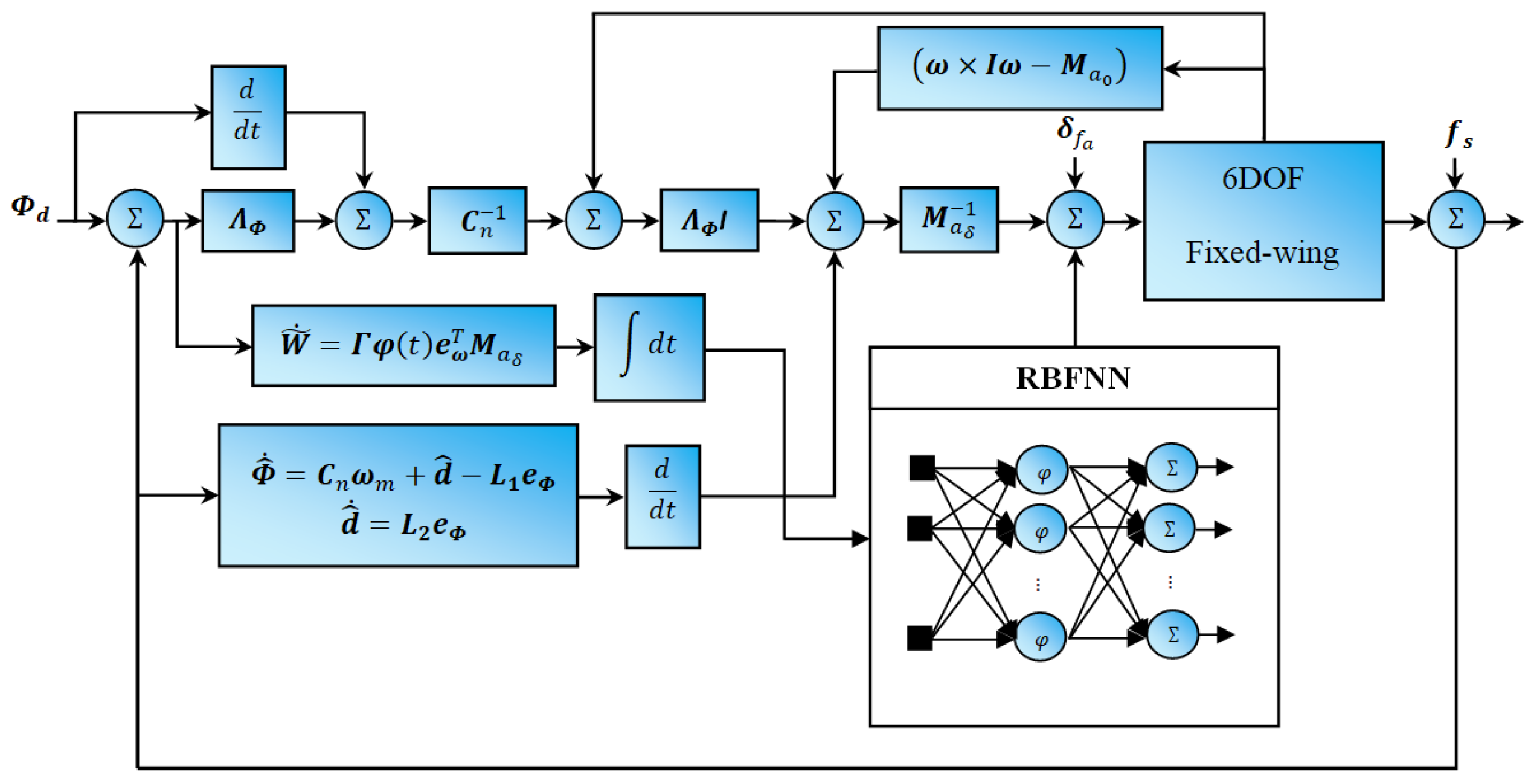
To compensate for the actuator fault, the NDI control law given in Equation (13) is modified as follows:
δ = M a δ 1 I Λ ω ω c ω + ω × I ω M a 0 δ ^ f a
Here, δ ^ f a is the estimated actuator fault given by δ ^ f a = W ^ T φ ( t ) . By applying the control law to the system, the following equation is obtained: e ˙ ω = Λ ω e ω + M a δ δ ˜ f a , where e ω = ω c ω and δ ˜ f a represents the error of the fault signal, defined as δ ˜ f a = δ f a δ ^ f a . Alternatively, it can be expressed as δ ˜ f a = W ˜ T φ ( t ) , where W ˜ T = W T W ^ T . The adaptation law is given as follows:
W ˜ ˙ = Γ φ ( t ) e ω T M a δ
Here, Γ is a positive definite matrix that satisfies the dimensions. To prove the stability of this control, the Lyapunov candidate function is used, which is defined as
V e ω , t = 1 2 e ω T e ω + 1 2 tr W ˜ T Γ 1 W ˜
Taking the time derivative of V yields
V ˙ e ω , t = e ω T e ˙ ω + tr W ˜ T Γ 1 W ˜ ˙
Substituting e ω in V ˙ , the expression becomes
V ˙ e ω , t = e ω T Λ ω e ω + e ω T M a 0 W ˜ T φ ( t ) + tr W ˜ T Γ 1 W ˜ ˙
Via the vector trace identity a T b = tr b a T , the formula simplifies to
V ˙ e ω , t = e ω T Λ ω e ω + tr W ˜ T φ ( t ) e ω T M a δ + Γ 1 W ˜ ˙
By employing the adaptation law Equation (18), it can be determined that V ˙ e ω , t = e ω T Λ ω e ω , where V ˙ is a negative definite function. Accordingly, the equilibrium point e ω = 0 3 × 1 in the slower angular loop is asymptotically stable, and the error e ω approaches zero as time approaches infinity, as established by the Lyapunov stability theorem [40]. Therefore, the adaptive FTC, depicted in Figure 5, is mathematically represented as
δ = M a δ 1 I Λ ω ω c ω + ω × I ω M a 0 W ^ T φ ( t )

3.5. Airspeed Control Design

Previous sections have focused primarily on controlling the attitude of the UAV. This section deals with the design of a control law for the speed of the UAV. Before proceeding with the controller design, it is convenient to clarify the dynamic model of the UAV’s speed. The UAV speed V a satisfies the relation V a 2 = V b T V b , then the dynamics are given by V ˙ a = 1 V a V b T V ˙ b . Now from (1), V ˙ a takes the form
V ˙ a = 1 m V a V b T R s b F a + F g + F T 1 V a V b T ω × V b
Since the term V b T ω × V b is zero, the equation simplifies to
V ˙ a = 1 m V a V b T R s b F a + F g + 1 m V a V b T F T
Alternatively, this can be expressed as
V ˙ a = 1 m V a V b T R s b F a + F g + u m V a 0.5 ρ S p K m δ t 2 V a 2
By applying the nonlinear dynamic inversion strategy described previously, the control law for airspeed is given by
δ t = 1 K m 1 0.5 ρ S p m V a u V ˙ a d + λ V a e V a 1 m V a V b T R s b F a + F g + V a 2
where e V a = V a d V a represents the airspeed error, V a d is the desired airspeed and λ V a is a positive constant. The control law in Equation (27) depends on the airspeed V a , which is measured by on-board sensors. However, these sensors are also prone to faults that may affect the accuracy of the V a readings and, consequently, the effectiveness of the control law. To address this issue, the observer developed in Section 3.1 is designed to detect and compensate for sensor faults, ensuring reliable measurements for stable control performance. Therefore, the partial model is considered.
V ˙ a = 1 m V a V b T R s b F a + F g + u m V a 0.5 ρ S p K m δ t 2 V a 2 V a m = V a + f s
Here, V a m and f s are the measured airspeed and sensor fault, respectively. The dynamics will be as follows: V ˙ a m = V ˙ a + f ˙ s . If the following is carried out, Δ = f ˙ s , then it will be:
V ˙ a m = 1 m V a V b T R s b F a + F g + u m V a 0.5 ρ S p K m δ t 2 V a 2 + Δ
In order to estimate the disturbance signal, the NDO designed in Section 3.1 is used. Then, the observer dynamic is given by:
V ^ ˙ a m = 1 m V a V b T R s b F a + F g + u m V a 0.5 ρ S p K m δ t 2 V a 2 + Δ ^ L 1 e V a Δ ^ ˙ = L 2 e V a f ^ s = 0 t Δ ^ d τ ,
where L 1 and L 2 satisfy Equation (8).

4. Linear Quadratic Regulator with Integral Action Design

In this section, a linear controller is introduced to allow a thorough comparison with the adaptive fault-tolerant controller, demonstrating the robustness and effectiveness of the latter in dealing with faults and uncertainties. The comparison focuses on a widely used linear control approach, the linear quadratic regulator with integral action (LQRI) [41]. To support this analysis, linear state-space models for both longitudinal and lateral motion are derived by linearising Equation (1) around the trim conditions (see [35] for details). The corresponding longitudinal and lateral variables are defined as follows.
x lon = u w q θ T ; u l o n = δ e δ t T x lat = v p r ϕ ψ T ; u l a t = δ a δ r T
The state-space linear model for longitudinal or lateral motion are given by
x ˙ j = A j x j + B j u j y j = C j x j + D j u j j = lon , lat
The design of a linear quadratic regulator with integral action (LQRI) involves extending the standard linear quadratic regulator (LQR) by introducing integral action to eliminate steady-state error. To eliminate the steady-state error, the integral state ζ j is introduced as ζ j = r j C j x j d t . The integral of the output error is added as an additional state. The augmented state vector is defined as x a j = x j ζ j T , and now the augmented system dynamics are:
x ˙ j ζ ˙ j = A j 0 C j 0 x j ζ j + B j 0 u j y j = C j 0 x j ζ j + D j u j
To control the augmented system the LQR controller used, the LQR controller minimises the quadratic cost function J = 0 x a j T Q a j x a j + u j T R j u j d t , where Q a j is a positive semi-definite state weighting matrix and R j is a positive definite control weighting matrix. Typically, Q a j is chosen to penalise deviations in the states and integral action. The optimal control law for the augmented system is u j = K j x a j , where K j is the LQR gain computed from K j = R j 1 B a j T P j , where P j is the solution to the Algebraic Riccati Equation (ARE):
A a j T P j + P j A a j T + P j B a j R j 1 B a j T P j + Q a j = 0

5. Simulation Results

This section investigates the effectiveness of the proposed fault-tolerant control law for attitude control for a fixed-wing UAV. The Aerosonde fixed-wing UAV model is used to implement the control laws and perform numerical simulations in MATLAB. The aerodynamic coefficients and parameters for the Aerosonde UAV are given in Table 1 and Table 2, respectively, as referenced in [35]. The parameters of the trim conditions and linearised longitudinal and lateral models are given in the Appendix A.
Without loss of generality, the actuator dynamics are simplified to a first-order lag filter. Whilst this model may not capture complex fault behaviours, it was considered for simplicity and to focus on the main features of the fault. Complex fault signals often exhibit a piecewise first order or even piecewise constant behaviour. The dynamics and limits for the aileron, rudder and elevator used in the simulation are described as follows:
δ a = 10 s + 10 δ a c δ e = 10 s + 10 δ e c δ r = 10 s + 10 δ r c δ a 20 ; δ e 20 ; δ r 20
Here, δ a c , δ e c and δ r c are the commended aileron, rudder and elevator. The Runge–Kutta method will be used to solve the differential equations with a time step of 0.001. The controller parameters used are as follows:
Λ Φ = 2 0 0 0 2 0 0 0 2 ; Λ ω = 500 0 0 0 500 0 0 0 500 ; Γ = 70 I m × m ; λ V a = 5 ;
To determine the parameters of the nonlinear perturbation observer, the optimisation problem presented in Section 3.1, defined by Equation (8), is solved using the fminunc function available in MATLAB.
L 1 = 71.4 L 2 = 893.7 λ 1 = 52.5 , λ 2 = 53.5
The basic hyperparameters of the RBF neural network used for the summation in this paper are as follows: the input is time, while the output is the estimated faults. The network consists of 51 neurons and uses a Gaussian activation function. The centre μ ’s for the Gaussian function is set to 0.5 for all neurons.
The fault scenarios for both actuators and sensors are set as:
δ a f = 0 0 0 t 8.5 δ a f = 0.2 0 0 0 0.25 0 0 0 0.3 δ + 0.12 t + 4.5 0.35 t + 3.7 0.21 t + 4.61 8.5 < t < 20 δ a f = 0 0 0 t 20 f s = 0 t 10 f s = 0.5 ( t 10 ) 2 + 2.7 10 < t < 20 f s = 35.25 t 20
The values used to design the LQRI and LQR linear controllers are given below:
Q a lon = d i a g 1 0 0 1 50 50 ; R lon = 0.001 0 0 0.05 Q a lat = d i a g 0 0 0 1 1 50 50 ; R lat = 0.01 0 0 0.01
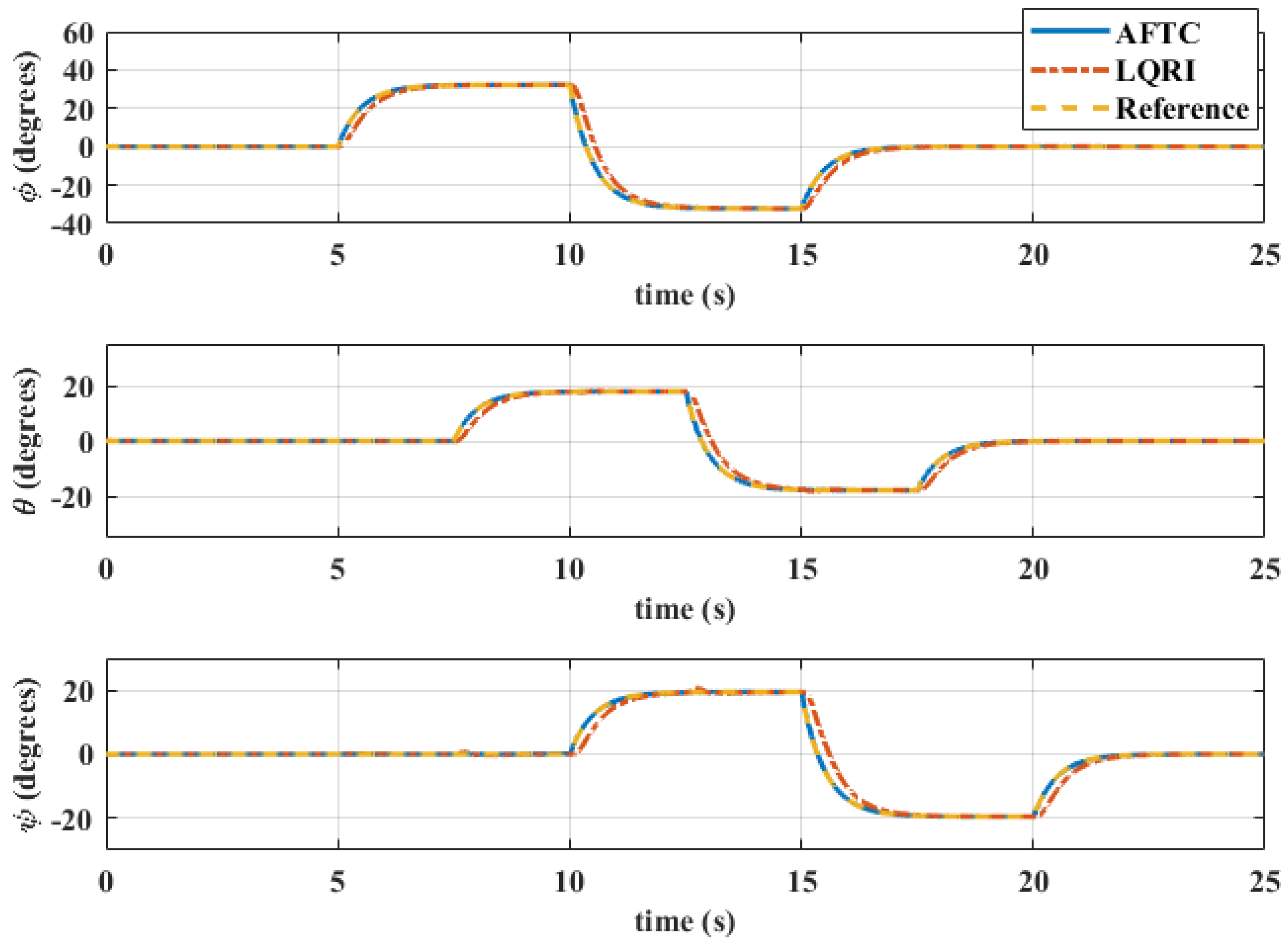
Figure 6 shows the evolution of the UAV’s attitude—roll, pitch and yaw—under nominal conditions, where the system maintains stable and accurate tracking. Small fluctuations due to external disturbances remain minimal, ensuring reliable performance. The control system responds quickly to dynamic changes, enabling smooth trajectory tracking and a quick return to steady-state behaviour. In the absence of faults, the LQRI controller performs similarly to the adaptive controller, achieving stable responses with minimal deviations. The LQRI controller further improves robustness by reducing steady-state errors, while overall differences in tracking accuracy and recovery times remain negligible.
Figure 7 shows the evolution of the UAV’s attitude, specifically the roll, pitch and yaw angles, under fault conditions. The attitude remains stable and closely follows the reference values even when the system experiences actuator faults. Although small disturbances occur at critical moments associated with actuator faults, these deviations remain within a narrow range, ensuring minimal impact on overall control and aircraft performance. In addition, the control system quickly adapts to changing dynamics with minimal delay, enabling reliable tracking and a rapid return to steady-state behaviour.
In contrast, the performance of the LQRI controller, as shown in the figure, demonstrates its limitations in handling actuator faults compared to the adaptive and fault-tolerant controller. While the LQRI controller incorporates an integral steady-state error mitigation component, offering some improvement in robustness, it still exhibits larger deviations from the reference trajectory and slower recovery times than the adaptive and fault-tolerant controllers. The inability of LQRI to adapt in real time to changing system dynamics results in prolonged transient errors and reduced tracking accuracy.
These limitations highlight the benefits of incorporating adaptive and fault-tolerant strategies to improve resilience and maintain optimal flight performance under fault conditions. Furthermore, no comparison with other nonlinear controllers was made, as comparisons with other nonlinear controllers are considered unnecessary, as adaptive control inherently balances indirect fault-tolerant and robust control strategies [42].
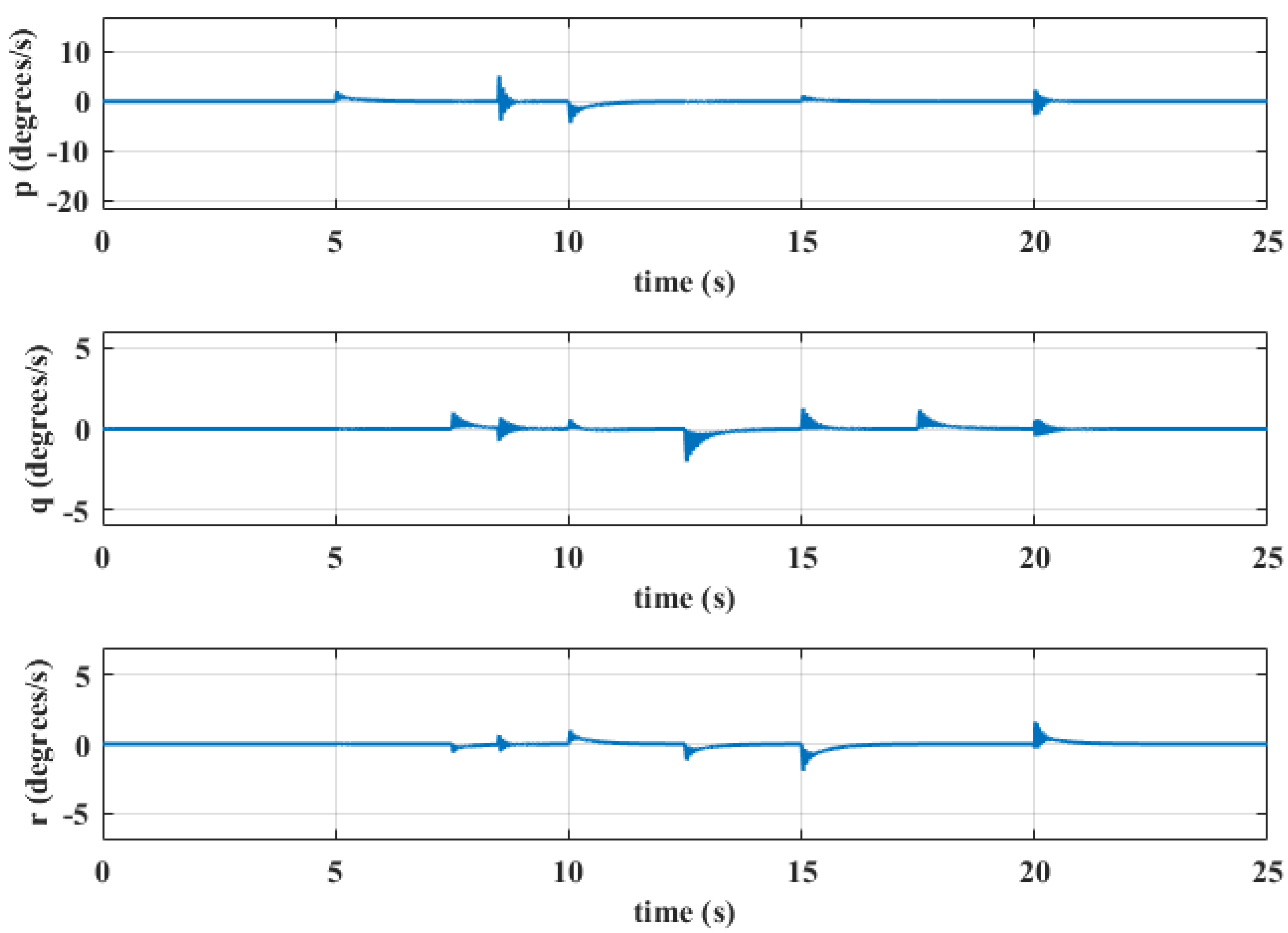
Figure 8 shows the angular velocity components, demonstrating smooth transitions and stability even under actuator fault conditions. Although small oscillations occur, the adaptive fault-tolerant control system effectively constrains these oscillations within a narrow range, minimising the risk of oscillatory drift commonly observed in systems without fault compensation. This highlights the effectiveness of nonlinear dynamic inversion in maintaining stable angular velocity.
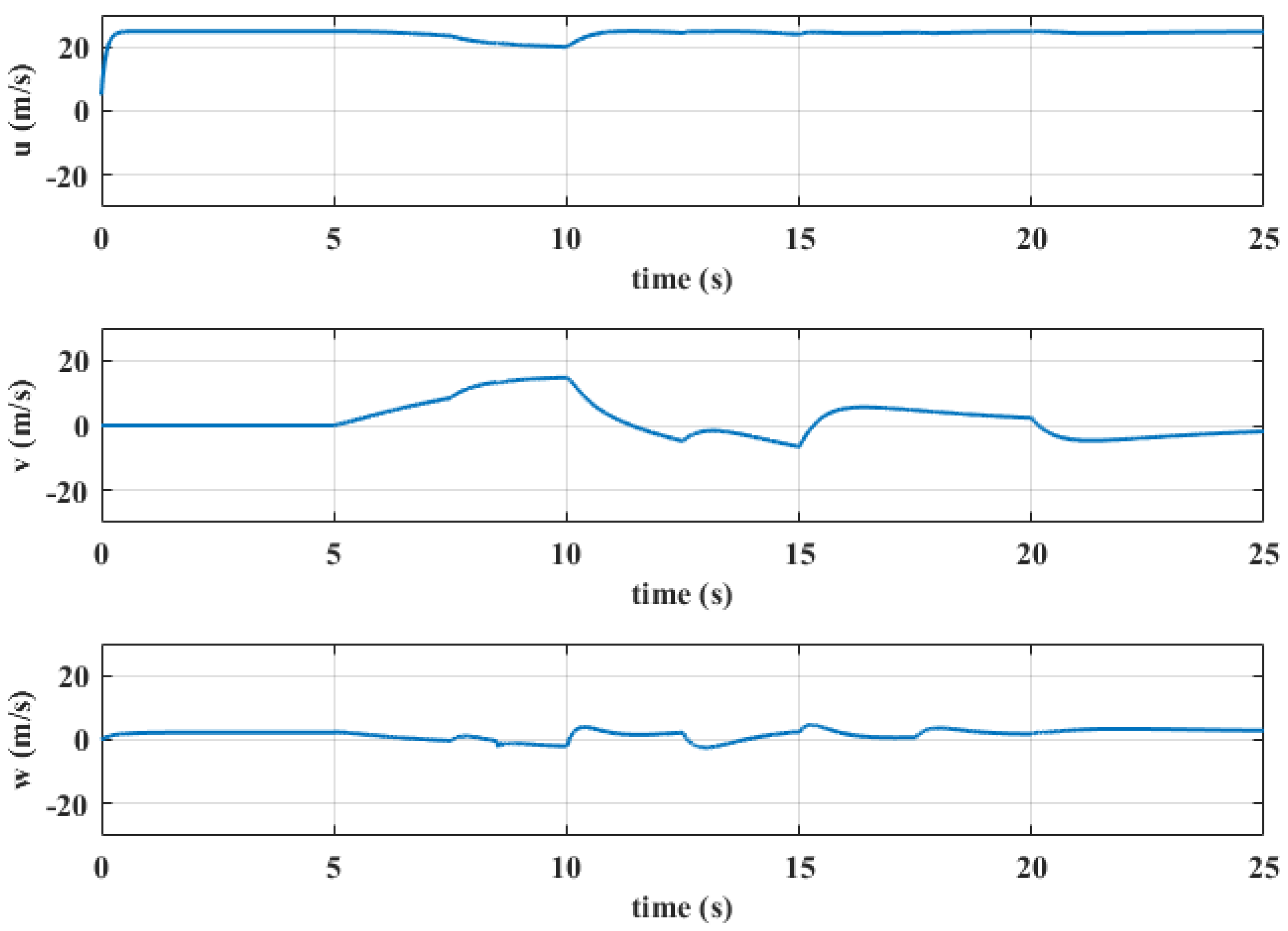
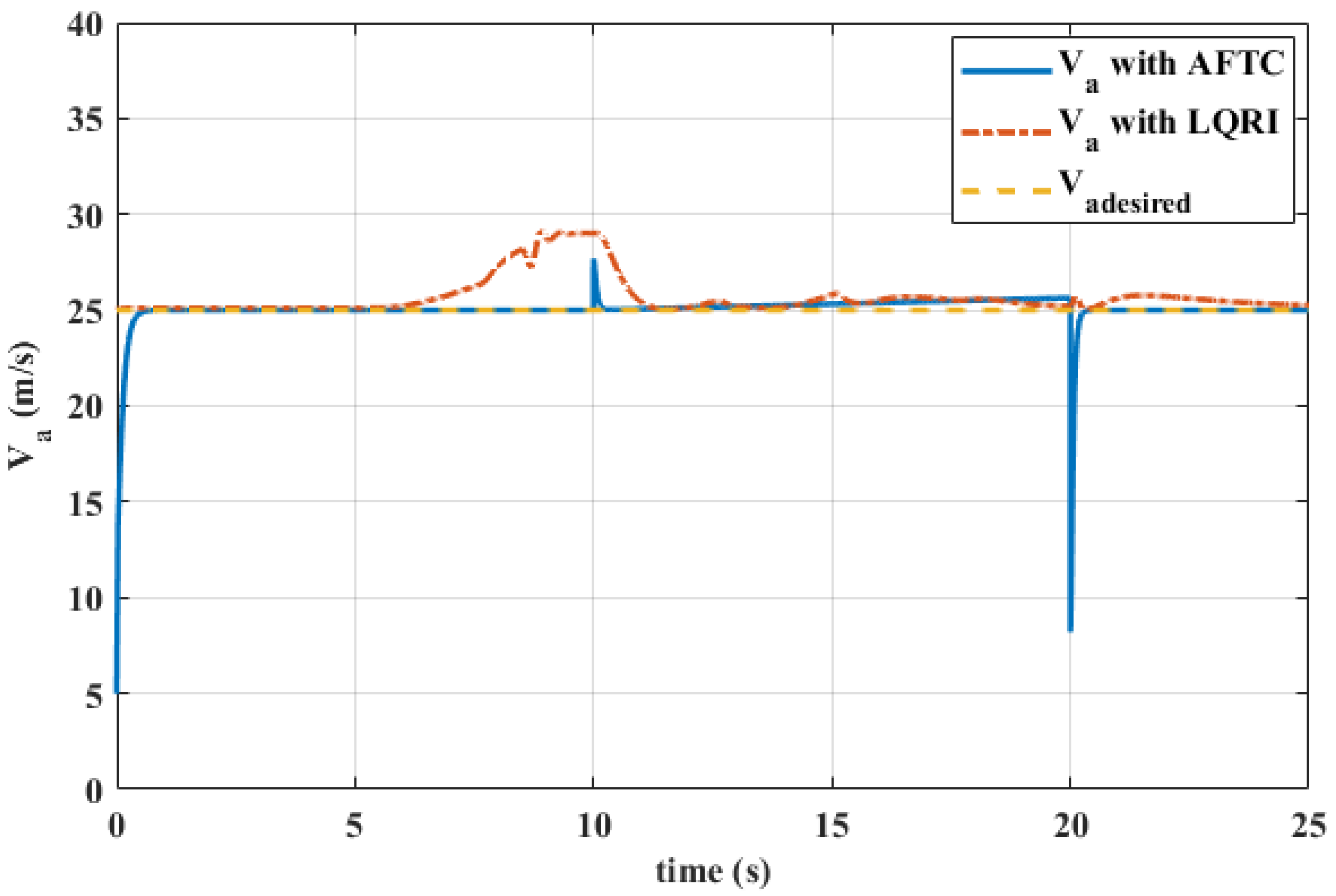
Figure 9 and Figure 10 show how effectively the combined UAV speed control law and fault-tolerant adaptive control law regulate the UAV’s attitude. The data show successful stabilisation of both the UAV’s overall speed and individual speed vector components, with minimal variations that do not compromise performance. In contrast, the results of the LQRI controller, shown in Figure 10, show significant deviations from the reference values, demonstrating its limitations in the face of airspeed sensor and actuator faults. While the LQRI controller improves performance by dealing with steady-state errors, its transient response shows more significant variations than the adaptive fault-tolerant controller. These comparative results provide further evidence of the reliability and advantages of the proposed adaptive control methodology in providing stable and accurate flight control despite sensor and actuator faults.
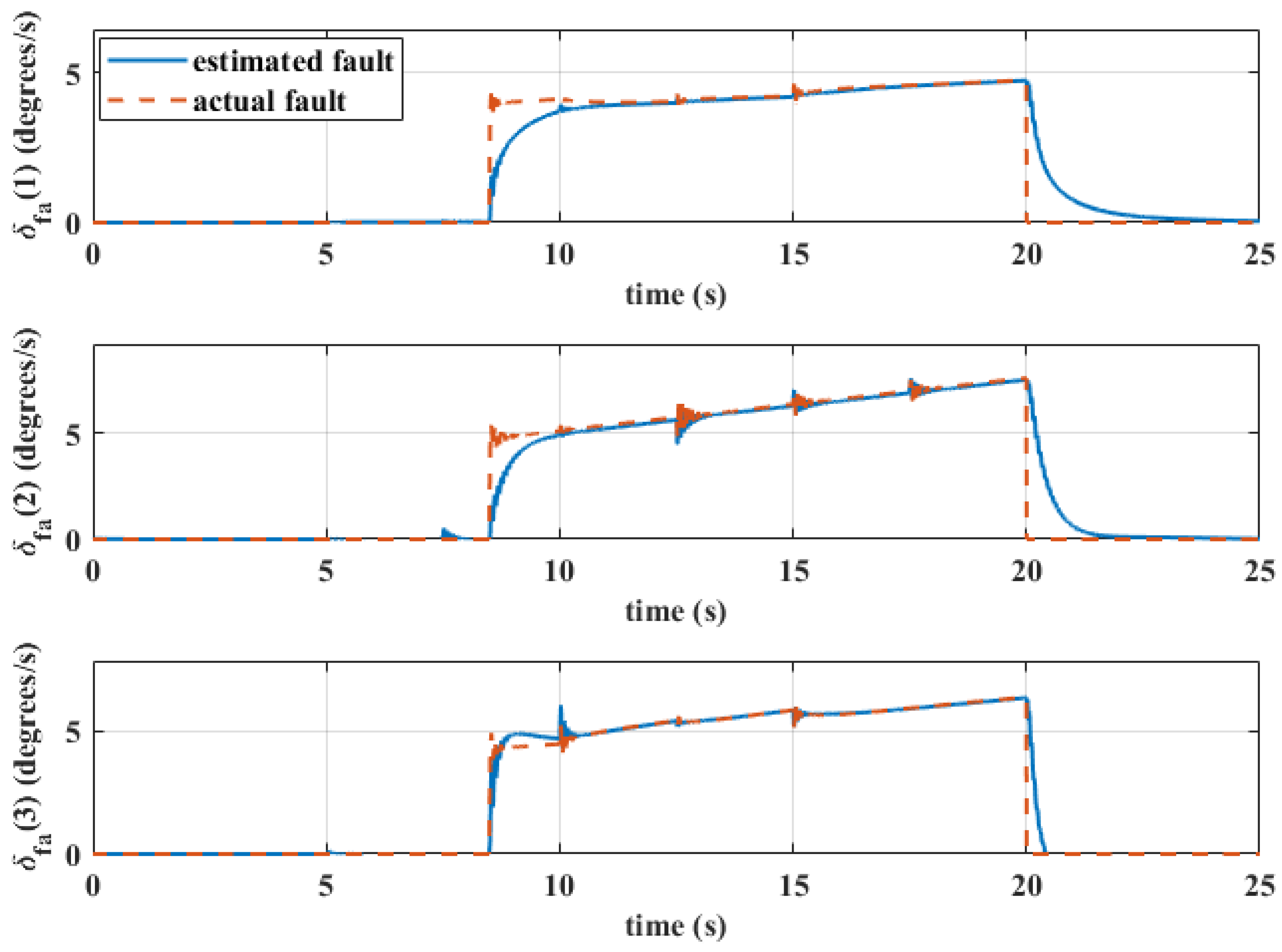
Figure 11 and Figure 12 show the throttle deflection together with the deflection of the control surfaces: elevator, aileron and rudder. It can be observed that the deflection of these control surfaces remains within the desired range 20 , 20 , reflecting the accuracy of the system in meeting the control requirements. Figure 13 shows the successful estimation of the intermittent during the abrupt and incipient changes, with a convergence time of approximately 2 s following the largest sudden variations.
This validates the theoretical predictions based on the Lyapunov stability criteria, confirming the reliability of the system in complex and disturbed environments.
Figure 14 highlights the effectiveness of the proposed nonlinear disturbance observer in dealing with sensor faults, showing a clear match between the estimated and actual values. This reflects the ability of the observer to detect faults and provide accurate estimates, which in turn are passed on to the controller to make the necessary adjustments. This rapid and accurate response minimises the likelihood of degraded UAV performance and enables the system to deal with fault conditions flexibly and reliably.
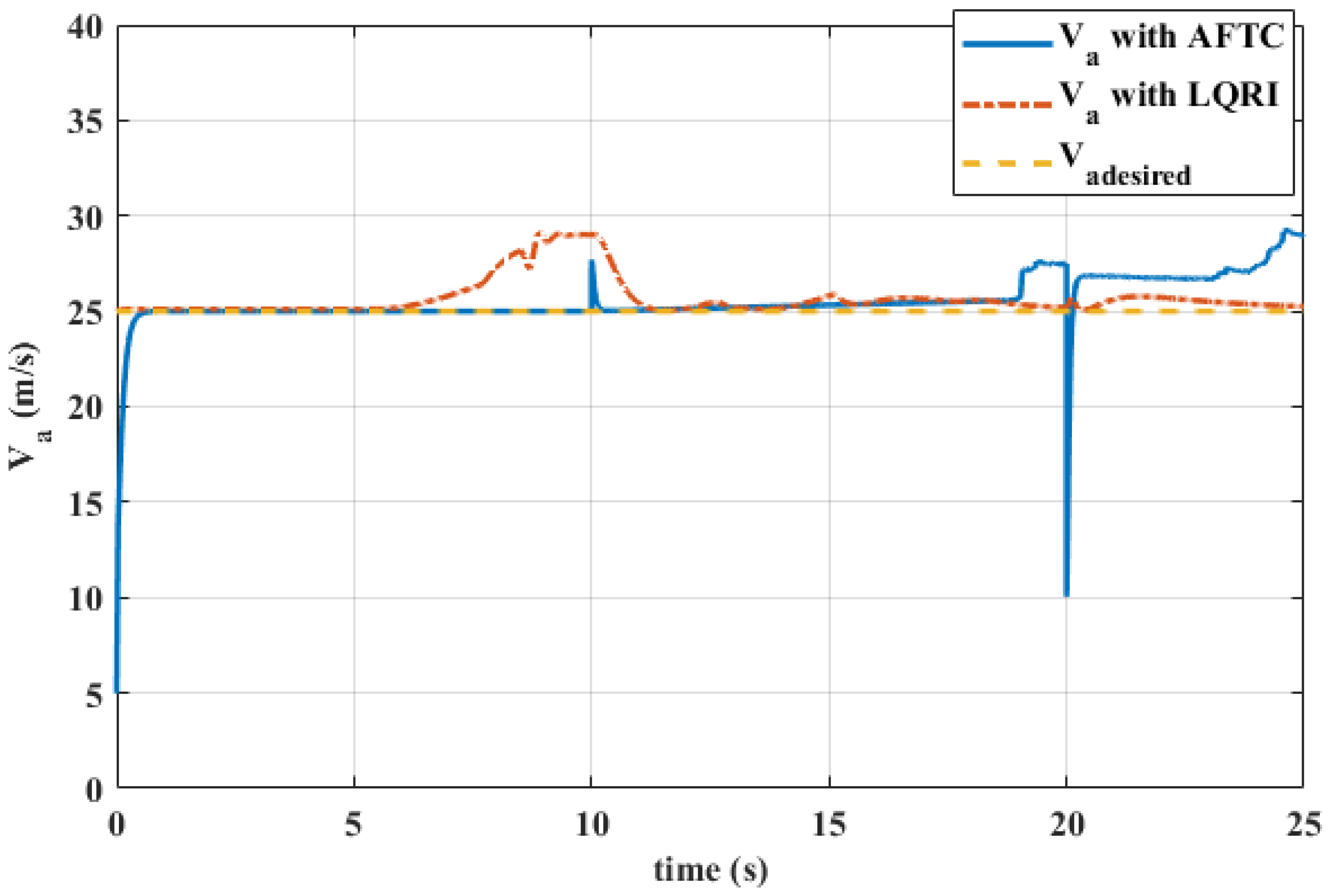
Figure 15 and Figure 16 show the attitude and velocity evolution of the UAV when the nonlinear disturbance observer is not integrated with the fault-tolerant control system. They show that without the NDO, the UAV becomes unstable due to sensor faults that the FTC alone cannot effectively deal with. This highlights the essential role of the proposed NDO in compensating for these faults, improving stability and ensuring robust UAV performance in the presence of model uncertainty.

6. Conclusions

This paper presents an adaptive fault-tolerant control strategy for fixed-wing UAVs that enables reliable operation under challenging conditions, such as icing, actuator and sensor faults, model uncertainties and external disturbances. The proposed control architecture integrates radial basis function neural networks with nonlinear dynamic inversion and a nonlinear disturbance observer to provide a comprehensive fault management solution. By using these advanced techniques, the approach ensures robust performance, stability and precise control under harsh environmental conditions.
Theoretical analysis, validated by Lyapunov stability criteria, confirms the robustness of the proposed methodology. Numerical simulations further demonstrate the effectiveness of the adaptive FTC system, showing its ability to maintain attitude stability, velocity control and fault compensation, even in scenarios where faults simultaneously affect actuators and sensors. Compared to the conventional LQRI controller, the proposed approach exhibits superior fault compensation and disturbance rejection, confirming its feasibility and improved resilience in fault-prone environments.
The novelty of this work lies in its integrated fault-tolerant design, which simultaneously handles nonlinear actuator and sensor faults through adaptive estimation and compensation, outperforming traditional control methods. This contribution improves the operational safety and reliability of UAVs under extreme conditions. Future research directions include extending the framework for energy optimisation and cooperative UAV missions to broaden its applicability in real-world scenarios.

Author Contributions

Conceptualisation, A.B., H.T. and Z.B.; methodology, all authors; software, A.B., H.T.; validation, A.B., T.S., H.T. and N.H.; formal analysis, all authors; investigation, all authors; resources, A.B., T.S., Z.B. and M.R.K.; data curation, A.B. and H.T.; writing—original draft preparation, all authors; writing—review and editing, all authors; supervision, H.T., M.R.K. and T.S. All authors have read and agreed to the published version of the manuscript.

Funding

This research received no external funding.

Data Availability Statement

The data presented in this study are available upon approved request from the first author, due to institutional ethical research and data management processes.

Conflicts of Interest

The authors declare no conflicts of interest.

Abbreviations

The following abbreviations are used in this manuscript:
UAVUnmanned Aerial Vehicles
DOFDegree Of Freedom
FTCFault-Tolerant Control
RBFRadial Basis Function
NDINonlinear Dynamic Inversion
NDONonlinear Disturbance Observer
LQRLinear Quadratic Regulator
LQRILinear Quadratic Regulator with Integral Action
AREAlgebraic Riccati Equation

Appendix A. Trimming Conditions and Linearised Model

The numerical values of the trimming conditions and linear system matrices for both longitudinal and lateral motion used as the basis for the analysis in this paper are given below:
x trim = 24.8903 0.0461 2.3380 0 0 0 0.0014 0.0014 0.0017 T u trim = 0.0047 0.1179 0.0057 0.3134 T A lon = 0.5138 0.3615 2.3380 9.8100 0.5721 2.3009 24.8903 0.0189 0.0519 0.5520 0.4988 0 0 0 1 0 ; B lon = 0 38.1332 0 0 18.2384 0 0 0 C lon = 1 0 0 0 0 0 0 1 ; D lon = 0 0 0 0 A lat = 0.6329 2.3380 24.8903 9.8100 0 3.1826 11.5766 5.1970 0 0 3.3703 0.3352 6.9172 0 0 0 1 0.0014 0 0 0 0 1 0 0 ; B lat = 0 2.7448 65.0418 79.5051 25.9808 6.0401 0 0 0 0 C lat = 0 0 0 1 0 0 0 0 0 1 ; D lat = 0 0 0 0

References

  1. Kim, J.; Kim, S.; Ju, C.; Son, H.I. Unmanned aerial vehicles in agriculture: A review of perspective of platform, control, and applications. IEEE Access 2019, 7, 105100–105115. [Google Scholar] [CrossRef]
  2. Lyu, M.; Zhao, Y.; Huang, C.; Huang, H. Unmanned aerial vehicles for search and rescue: A survey. Remote Sens. 2023, 15, 3266. [Google Scholar] [CrossRef]
  3. Greenwood, W.W.; Lynch, J.P.; Zekkos, D. Applications of UAVs in civil infrastructure. J. Infrastruct. Syst. 2019, 25, 04019002. [Google Scholar] [CrossRef]
  4. Vasiloni, A.; Guyvenchy, F.; Pașcalău, R.; Șmuleac, A. Use of UAV technology for environmental conservation. Res. J. Agric. Sci. 2023, 55, 4. [Google Scholar]
  5. Telli, K.; Kraa, O.; Himeur, Y.; Ouamane, A.; Boumehraz, M.; Atalla, S.; Mansoor, W. A comprehensive review of recent research trends on unmanned aerial vehicles (UAVs). Systems 2023, 11, 400. [Google Scholar] [CrossRef]
  6. Fourlas, G.K.; Karras, G.C. A survey on fault diagnosis and fault-tolerant control methods for unmanned aerial vehicles. Machines 2021, 9, 197. [Google Scholar] [CrossRef]
  7. Henna, H.; Toubakh, H.; Kafi, M.R.; Sayed-Mouchaweh, M. Towards fault-tolerant strategy in satellite attitude control systems: A review. Annu. Conf. PHM Soc. 2020, 12, 14. [Google Scholar] [CrossRef]
  8. Zogopoulos-Papaliakos, G.; Karras, G.C.; Kyriakopoulos, K.J. A fault-tolerant control scheme for fixed-wing with flight envelope awareness. J. Intell. Robot. Syst. 2021, 102, 46. [Google Scholar] [CrossRef]
  9. Hann, R.; UNTNU. 2nd international UAV Icing Workshop: Book of abstracts. UAV Icing Workshop, Trondheim, Norway. 3 December 2024. Available online: https://zenodo.org/records/14274740 (accessed on 1 March 2025).
  10. Souanef, T. Adaptive Guidance and Control of Small Unmanned Aerial Vehicles. Ph.D. Thesis, Universität Stuttgart, Stuttgart, Germany, 2019. [Google Scholar]
  11. Souanef, T. L1 Adaptive Output Feedback Control of Small Unmanned Aerial Vehicles. Unmanned Syst. 2023, 11, 249–260. [Google Scholar] [CrossRef]
  12. Emami, S.; Banazadeh, A. Fault-tolerant predictive trajectory tracking of an air vehicle based on acceleration control. IET Control Theory Appl. 2020, 14, 750–762. [Google Scholar] [CrossRef]
  13. Hu, X.; Zong, G.; Deng, X.; Wang, W. Model predictive control-based non-linear fault-tolerant control for air-breathing hypersonic vehicles. IET Control Theory Appl. 2014, 8, 1147–1153. [Google Scholar] [CrossRef]
  14. Zhang, C.; Zhang, G.; Dong, Q. Fixed-time disturbance observer-based nearly optimal control for reusable launch vehicle with input constraints. ISA Trans. 2022, 122, 182–197. [Google Scholar] [CrossRef]
  15. Almutairi, S.H.; Aouf, N. Fault-tolerant flight control design against actuator impairments using optimal control and fault compensation. In Proceedings of the 11th IEEE International Conference on Control & Automation (ICCA), Taichung, Taiwan, 18–20 June 2014. [Google Scholar]
  16. Zhang, Y.; Tang, S.; Guo, J. Adaptive-gain fast super-twisting sliding mode fault-tolerant control for a reusable launch vehicle in reentry phase. ISA Trans. 2017, 71, 380–390. [Google Scholar] [CrossRef] [PubMed]
  17. Liang, X.; Zhang, Y.; Zhang, B.; Peng, Y. Fixed-time observer-based fault-tolerant attitude control for reusable launch vehicle with actuator faults. Aerosp. Sci. Technol. 2020, 107, 106314. [Google Scholar] [CrossRef]
  18. Mahboub, M.A.; Rouabah, B.; Kafi, M.R.; Toubakh, H. Health management using fault detection and fault-tolerant control of multicellular converter applied in more electric aircraft system. Diagnostyka 2022, 23, 2. [Google Scholar] [CrossRef]
  19. Ma, X.; Liu, S.; Cheng, H. Civil aircraft fault-tolerant attitude tracking based on extended state observers and nonlinear dynamic inversion. J. Syst. Eng. Electron. 2022, 33, 180–187. [Google Scholar] [CrossRef]
  20. Meng, Y.; Jiang, B.; Qi, R. Adaptive fault-tolerant attitude tracking control of hypersonic vehicle subject to unexpected centroid-shift and state constraints. Aerosp. Sci. Technol. 2019, 95, 105515. [Google Scholar] [CrossRef]
  21. Saied, M.; Belkacem, A.; Khenfouch, M. BFA fuzzy logic-based control allocation for fault-tolerant control of multirotor UAVs. Aeronaut. J. 2019, 123, 1356–1373. [Google Scholar] [CrossRef]
  22. Long, H.; Wang, Z.; Guo, L.; Li, J. Fixed-time adaptive fuzzy fault-tolerant control of flapping wing MAVs with wing damage. IEEE Trans. Aerosp. Electron. Syst. 2024, 60, 6594–6607. [Google Scholar] [CrossRef]
  23. Zhang, C.; Luo, H.; Li, J.; Wang, Z. Neural-networks and event-based fault-tolerant control for spacecraft attitude stabilization. Aerosp. Sci. Technol. 2021, 114, 106746. [Google Scholar] [CrossRef]
  24. Lombaerts, T.; Ankersen, F.; Mulder, T.; Voskuijl, M. Dynamic inversion based full envelope flight control for an eVTOL vehicle using a unified framework. In Proceedings of the AIAA Scitech 2020 Forum, Orlando, FL, USA, 6–10 January 2020. [Google Scholar]
  25. Dong, Z.; Liu, K.; Wang, S. Sliding mode disturbance observer-based adaptive dynamic inversion fault-tolerant control for fixed-wing UAV. Drones 2022, 6, 295. [Google Scholar] [CrossRef]
  26. Zhang, L.; Mu, J.; Ma, H.; Dai, G.; Tong, S. Research on fault-tolerant control of combined airframe damage of electric aircraft. Aerospace 2023, 10, 611. [Google Scholar] [CrossRef]
  27. Jiang, F.; Liu, X.; Chen, T.; Li, K. Research on an Ice Tolerance Control Method for Large Aircraft Based on Adaptive Dynamic Inversion. Actuators 2024, 227. [Google Scholar] [CrossRef]
  28. Wang, H.; Zhou, X.; Tian, Y. Robust adaptive fault-tolerant control using RBF-based neural network for a rigid-flexible robotic system with unknown control direction. Int. J. Robust Nonlinear Control 2022, 32, 1272–1302. [Google Scholar] [CrossRef]
  29. Hou, Z.; Lan, X. Adaptive sliding mode and RBF neural network-based fault-tolerant attitude control for spacecraft with unknown uncertainties and disturbances. Adv. Space Res. 2024, 74, 1680–1692. [Google Scholar] [CrossRef]
  30. Ding, S.; Zhai, Q.; Liu, J.; Ma, J.; Qiu, Y. Disturbance observer design for nonlinear systems represented by input–output models. IEEE Trans. Ind. Electron. 2019, 67, 1222–1232. [Google Scholar] [CrossRef]
  31. He, Q.; Zhao, J.; Hu, X.; Wang, G.; Yan, J. Reconfigurable nonlinear dynamic inversion for attitude control of a structurally damaged aircraft. IEEE Access 2020, 8, 199931–199943. [Google Scholar] [CrossRef]
  32. Xue, Y.X.; Yan, L.; Sun, X.; Ma, D. Adaptive fault-tolerant control for carrier-based UAV with actuator failures. Aerosp. Sci. Technol. 2020, 107, 106227. [Google Scholar] [CrossRef]
  33. Zhou, Y.; Liu, H.; Guo, H. L 1 adaptive output-feedback fault-tolerant control for uncertain nonlinear systems subject to unmodeled actuator dynamics and faults. Trans. Inst. Meas. Control 2022, 44, 2177–2192. [Google Scholar] [CrossRef]
  34. Iglesis, E.; Horri, N.; Brusey, J.; Dahia, K.; Piet-Lahanier, H. Simultaneous actuator and sensor faults estimation for aircraft using a jump-Markov regularized particle filter. In Proceedings of the 2021 IEEE International Conference on Prognostics and Health Management (ICPHM), Detroit (Romulus), MI, USA, 7–9 June 2021. [Google Scholar]
  35. Beard, R.W.; McLain, T.W. Small Unmanned Aircraft: Theory and Practice; Princeton University Press: Princeton, NJ, USA, 2012. [Google Scholar]
  36. Cecilia, A. Advances in Nonlinear Observer Design for State and Parameter Estimation in Energy Systems; Springer Nature: Berlin/Heidelberg, Germany, 2023. [Google Scholar]
  37. Snell, S.A. Nonlinear Dynamic-Inversion Flight Control of Supermaneuverable Aircraft; University of Minnesota: Minneapolis, MN, USA, 1991. [Google Scholar]
  38. Safwat, E.; Farag, M.; El-Bardini, M.; Bayoumi, A. Robustness analysis of modified incremental nonlinear dynamic inversion for small UAVs. Autom. Control. Comput. Sci. 2020, 54, 128–138. [Google Scholar] [CrossRef]
  39. Lavretsky, E.; Wise, K.A. Robust and Adaptive Control with Aerospace Applications; Springer: London, UK, 2013. [Google Scholar]
  40. Slotine, J.J.E.; Li, W. Applied Nonlinear Control; Prentice Hall: Englewood Cliffs, NJ, USA, 1991. [Google Scholar]
  41. Stevens, B.L.; Lewis, F.L.; Johnson, E.N. Aircraft Control and Simulation: Dynamics, Controls Design, and Autonomous Systems; John Wiley & Sons: Hoboken, NJ, USA, 2015. [Google Scholar]
  42. Souanef, T. Multiple model l 1 adaptive fault-tolerant control of small unmanned aerial vehicles. J. Aerosp. Eng. 2024, 37, 04023103. [Google Scholar] [CrossRef]
Figure 1. Adaptive FTC strategy for a fixed-wing UAV.
Aerospace 12 00261 g001
Figure 2. Block diagram of NDI control.
Aerospace 12 00261 g002
Figure 3. NDI control strategy for fixed-wing UAV block diagram.
Aerospace 12 00261 g003
Figure 4. Radial basis function neural network.
Aerospace 12 00261 g004
Figure 5. Adaptive FTC control for fixed-wing UAV.
Aerospace 12 00261 g005
Figure 6. Time evolution of the attitude of the UAV in the absence of faults.
Aerospace 12 00261 g006
Figure 7. Time evolution of the attitude of the UAV in the presence of faults.
Aerospace 12 00261 g007
Figure 8. Time evolution of the angular velocities of the UAV.
Aerospace 12 00261 g008
Figure 9. Time evolution of the velocity components of the UAV.
Aerospace 12 00261 g009
Figure 10. Time evolution of the axial speed of the UAV.
Aerospace 12 00261 g010
Figure 11. Time evolution of the throttle input deflection.
Aerospace 12 00261 g011
Figure 12. Time evolution of the control surfaces of the UAV.
Aerospace 12 00261 g012
Figure 13. Time evolution of the actuator faults estimation.
Aerospace 12 00261 g013
Figure 14. Time evolution of the sensor faults estimation.
Aerospace 12 00261 g014
Figure 15. Time evolution of the UAV attitude without a disturbance observer.
Aerospace 12 00261 g015
Figure 16. Time evolution of the UAV velocity components without a disturbance observer.
Aerospace 12 00261 g016
Table 1. Aerodynamic coefficients for the Aerosonde UAV.
CoefficientValueCoefficientValue
C L 0 0.28 C n 0 0
C D 0 0.03 C Y β −0.98
C m 0 −0.02338 C l β −0.12
C L α 3.45 C n β 0.25
C D α 0.30 C Y p 0
C m α −0.38 C l p −0.26
C L q 0 C n p 0.022
C D q 0 C Y r 0
C m q −3.6 C l r 0.14
C L δ e −0.36 C n r −0.35
C D δ e 0 C Y δ a 0
C m δ e −0.5 C l δ a 0.08
C n δ r −0.032 C n δ a 0.06
C Y 0 0 C Y δ r −0.17
C l 0 0 C Y δ r 0.105
Table 2. Parameters for the Aerosonde UAV.
ParameterValueParameterValue
m 31.5 ( kg ) b 2.8956 ( m )
I x 0.8244 kg / m 2 c ¯ 0.18994 ( m )
I y 1.135 kg / m 2 S p 0.2027 m 2
I z 1.759 kg / m 2 ρ 1.2682 kg / m 3
I x z 0.1204 kg / m 2 K m 80 ( )
S 0.55 m 2
Disclaimer/Publisher’s Note: The statements, opinions and data contained in all publications are solely those of the individual author(s) and contributor(s) and not of MDPI and/or the editor(s). MDPI and/or the editor(s) disclaim responsibility for any injury to people or property resulting from any ideas, methods, instructions or products referred to in the content.