Article

Experimental Validation of Clamping-Type Mesh Fastening Method Using Thin Plates and Push-Button Rivets for Deployable Mesh Antennas

1
Department of Aerospace and Mechanical Engineering, Korea Aerospace University, 76 Hanggongdaehak-ro, Deogyang-gu, Goyang-si 10540, Republic of Korea
2
STEP Lab. Ltd., 43 Bogyongdong-ro, Yuseong-gu, Daejeon 34202, Republic of Korea
*
Author to whom correspondence should be addressed.
Aerospace 2025, 12(3), 248; https://doi.org/10.3390/aerospace12030248
Submission received: 31 December 2024 / Revised: 28 February 2025 / Accepted: 14 March 2025 / Published: 17 March 2025
(This article belongs to the Section Astronautics & Space Science)

Abstract

:
Deployable mesh antennas offer advantages such as high gain, ultra-light weight, and high packaging efficiency. However, the mesh that constitutes the reflection surface is prone to deformation due to its low stiffness, which directly affects the performance of the antenna. Therefore, it is essential to minimize the mechanical deformation of the mesh caused by external forces in order to achieve the target performance. In particular, the fastening interface between the mesh and the antenna structure is a critical area where high tensile forces are incurred due to the dynamic behavior of the antenna structure during ground tests, launch environments, and on-orbit operation. This causes degradation in the precision of the reflection surface. Therefore, an important part of the antenna development process is researching mesh fabric fastening methods that minimize the deformation of the reflection surface. Nevertheless, existing studies have only briefly mentioned mesh fastening methods, with limited systematic analysis of their impact on the mechanical properties of mesh fabric. In this paper, we propose a clamping-type mesh fastening method that combines push-button rivets and thin plates, which have high workability during mesh assembly, and conduct experimental validation. The characteristics of each fastening method were analyzed through tensile strength tests conducted at the mesh fabric level, and the results of the repeated tensile tests verified the effectiveness of the proposed fastening method.

1. Introduction

The space industry is experiencing increased interest and investments due to the advent of the New Space era and the Artemis program, which is NASA’s manned lunar mission involving 40 countries. In response, space payload technology is advancing, and performance requirements are constantly increasing. In particular, small satellites are rapidly evolving due to their advantages of low costs, short development periods, and potential for mass production. This has made it possible to operate a constellation of small satellites, and the reduced revisit cycle has enabled missions such as quasi-real-time Earth observation, high-speed communication, and signal intelligence (SIGINT), which were impossible to realize with conventional medium and large satellite systems [1,2,3,4,5]. In advanced space missions, synthetic aperture radar (SAR) and communications satellites require high-gain antennas to achieve their target performance. The performance of an antenna is proportional to its reflection surface area, making it the largest component in terms of weight and volume on satellites where it serves as the main payload. However, due to the volume requirements inside launch vehicles, the applicable diameter of fixed antennas is limited. To overcome the aforementioned problems, high-performance large antennas are increasingly adopting deployable structures. Interest in deployable mesh antennas is increasing because they offer lightweight design and increased stowage efficiency [6].
In a deployable mesh antenna, the mesh fabric is an important factor in determining the antenna’s performance. Antenna gain is a key performance metric, defined as the antenna’s directivity minus any antenna loss. Antenna loss is caused by the shape and material of the reflection surface. In addition, the mesh weave density, measured as the openings per inch (OPI), is characterized as the proportional increase in loss minimization as the operating frequency band of the antenna mission increases, with optimized OPI requirements for each frequency band [7,8]. This means that the mechanical and electrical properties of the mesh fabric that constitute the reflective surface, such as the material, weave pattern, and surface precision, directly affect the performance of the antenna. Therefore, mesh fabrics for space applications are manufactured using metal wires such as molybdenum and tungsten, which have low ductility and high strength compared to general textile materials. This ensures the structural safety of the mesh in the launch environment and maintains the precision of the antenna reflection surface during on-orbit operation [7]. However, the low ductility of metal mesh, mechanical deformation, or slip at the mesh fastening points due to external forces, such as assembly, mesh fastening, repeated ground tests, and dynamic behavior of the antenna structure in the launch environment, can cause a failure to maintain the curvature of the reflection surface and change the OPI. To avoid this degradation of the radio frequency (RF) performance and mission capability, it is essential to study the fastening methods between the antenna structure and the mesh fabric. In conventionally developed parabolic mesh antennas, the mesh fabric is sewn to the antenna structure using wires that do not affect RF characteristics without direct reference to detailed mesh fastening methods and processes [9,10,11,12]. To the best of the authors’ knowledge, no published studies have analyzed the mechanical properties of mesh fabrics based on the applied fastening methods, including sewing methods. In addition, it is difficult to maintain the tensile force of mesh fabric using manual fastening, and there are limitations, such as workspace constraints and decreased work efficiency, as the antenna size increases.
In this study, the clamping-type mesh fastening method using push-button rivets with high workability is proposed to overcome the disadvantages of the above fastening methods. The proposed mesh fastening method involves placing a mesh fabric in front of the main reflector structure of the antenna, overlaying it with a thin plate, and fixing it with push-button rivets. This is advantageous in terms of distributing the stresses acting on the mesh, with a wide fastening surface compared to the conventional sewing methods, which are limited by boundary conditions close to the point of contact. Additionally, the flexibility of the thin plate helps maintain the curvature of the reflection surface, as it can be attached to match the curvature of the main reflector rib. Furthermore, the fastening process is simple, as push-button rivets are used to fix the mesh fastening interfaces at uniformly spaced intervals, resulting in high workability. Tensile strength tests were conducted under various fastening conditions to characterize the mesh fabric constructed using the proposed method. The results of these tensile strength tests compared to those of repeated tensile tests for each fastening method verify the effectiveness of the proposed method.

2. Design Description of the Clamping-Type Mesh Fastening Method

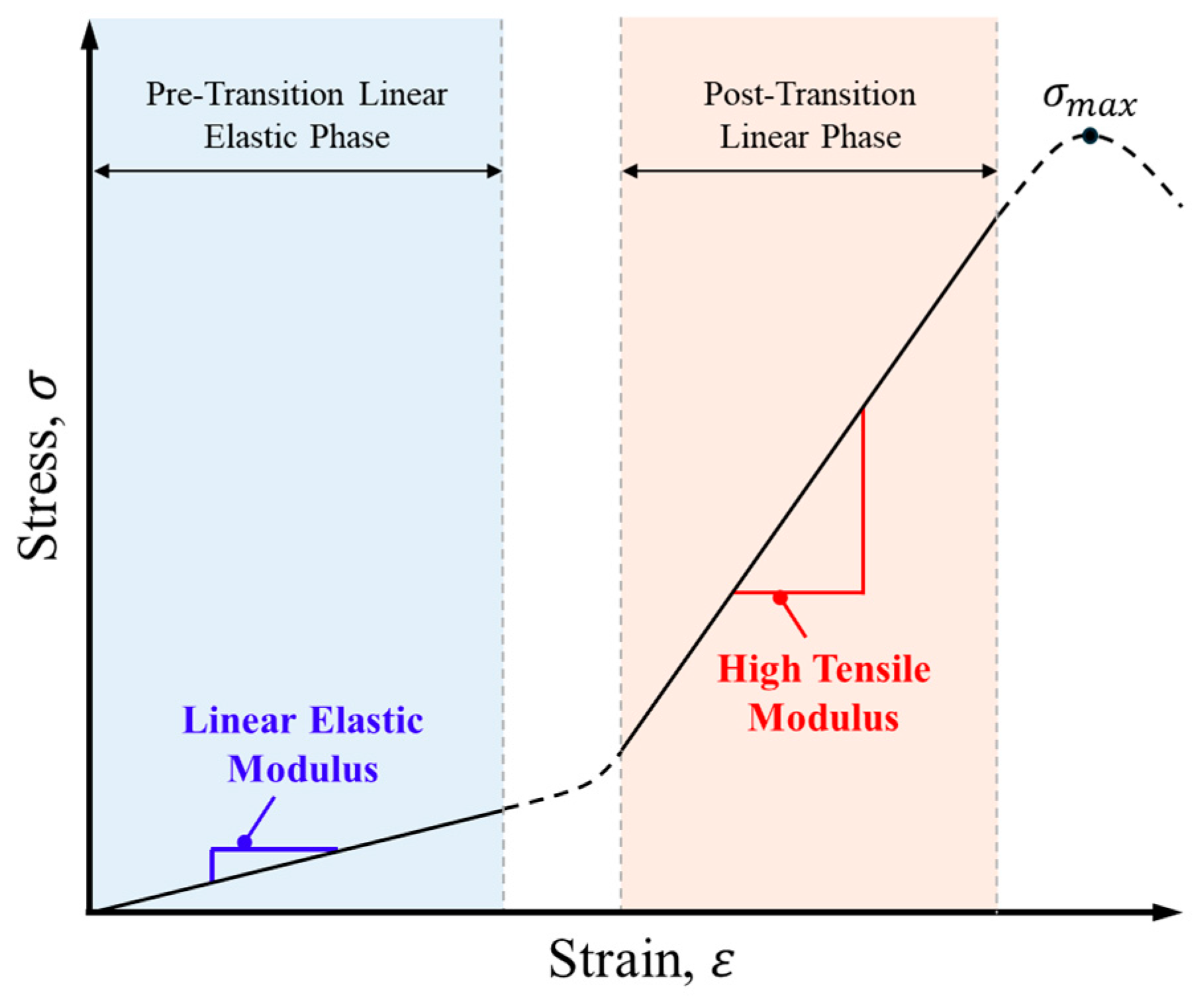
2.1. Overview of Mesh Fabrics for Space Applications

In mesh antennas for space applications, metal wires with low ductility and high strength characteristics are typically woven into a fabric to serve as a reflection surface. The wire surfaces are gold-plated to prevent oxidation of the wire in the on-orbit environment, maintain low contact resistance, and improve the electrical conduction properties [7]. During the weaving process, the optimal weave density and pattern are woven considering the antenna operating frequency band, the mechanical properties of the wire material, etc. Commonly applied patterns include tricot, atlas, atlas–atlas, and satin; Figure 1 shows examples of mesh weave pattern shapes [13,14,15]. In addition, due to the characteristic of mesh fabrics woven by crossing wires, openings are generated at uniform intervals. This characteristic allows the OPI to be used as a unit that represents the weave density of the mesh fabric, indicating the number of mesh openings per inch. As the operating frequency band of the antenna increases, the reflection loss can be minimized by increasing the OPI. Generally, 10, 20, and 40 OPI are applied in the S-, X-, and Ka-bands, respectively [7].
Figure 2 shows the J-shaped stress–strain curve of soft tissues [16]. Mesh fabrics are flexible due to their continuous weaving patterns and exhibit J-shaped behavior compared to single yarns, which exhibit linear stress–strain behavior. In the low-stress region, the elasticity of the fabric allows for large deformations. After the nonlinear transition phase, the fabric’s stiffness increases, exhibiting behavior similar to a single yarn [17,18]. These characteristics have mainly been studied in the field of biomechanical engineering and can be observed in knitted fabrics that are similar to biological tissue. Due to these characteristics, the change in tension of gold-plated molybdenum mesh fabrics is insignificant at a strain of 0.25%, even under extreme temperatures ranging from −180 °C to 300 °C, which may be caused by the gold in the on-orbit environment. In addition, the high elastic modulus and strength of molybdenum, combined with the flexibility of the knitted structure, are advantageous for maintaining the shape of the reflection surface in the on-orbit environment [7]. In this study, the optimal mesh fastening method was identified, and its feasibility was analyzed by evaluating the equivalent stiffness in the linear elastic modulus (LEM) region based on the J-shaped characteristic of the mesh. Additionally, fastening force analysis was performed based on the equivalent stiffness in the high tensile modulus (HTM) region, where strong stresses occur at the fastening points in the elastic region of the mesh fabric.

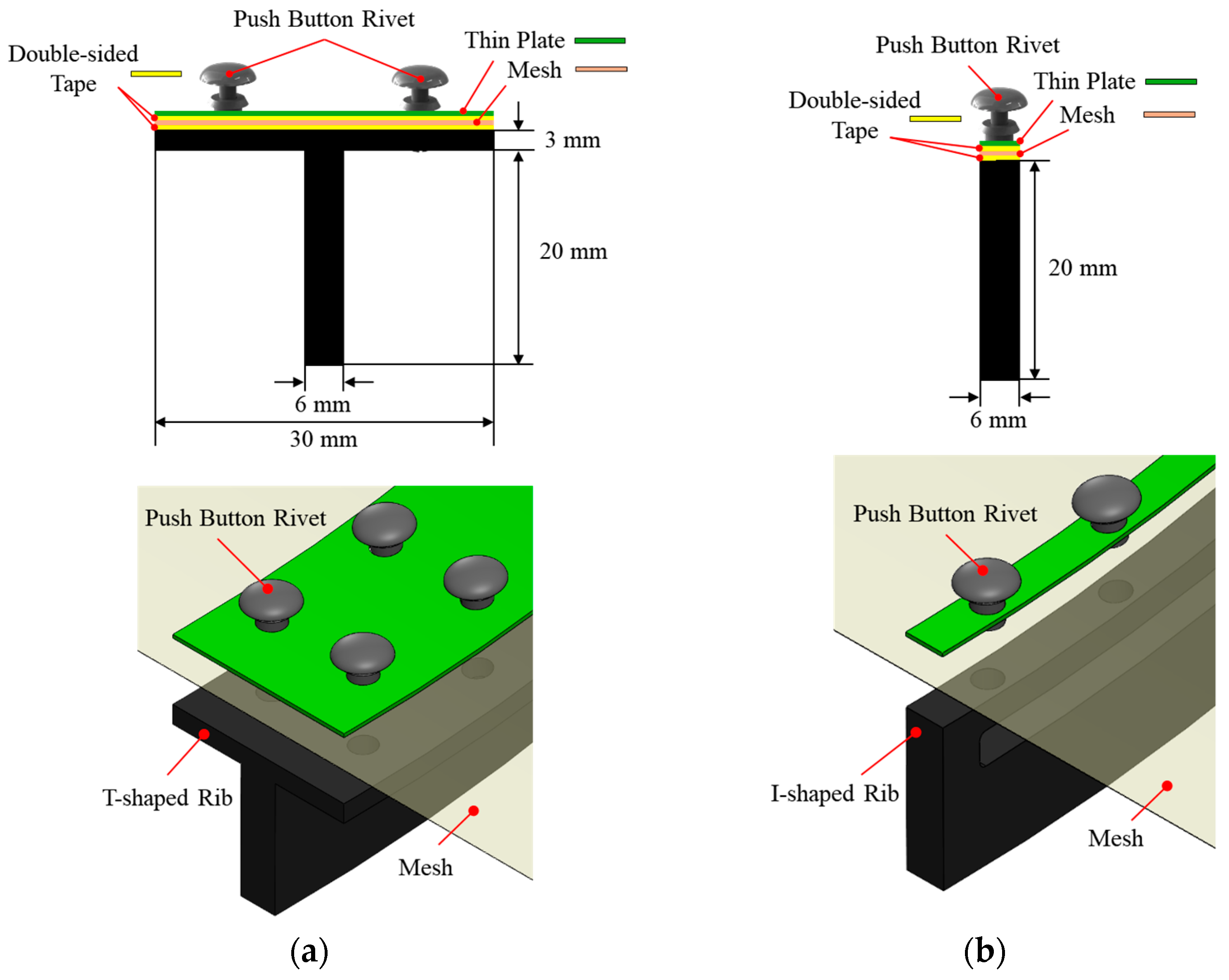
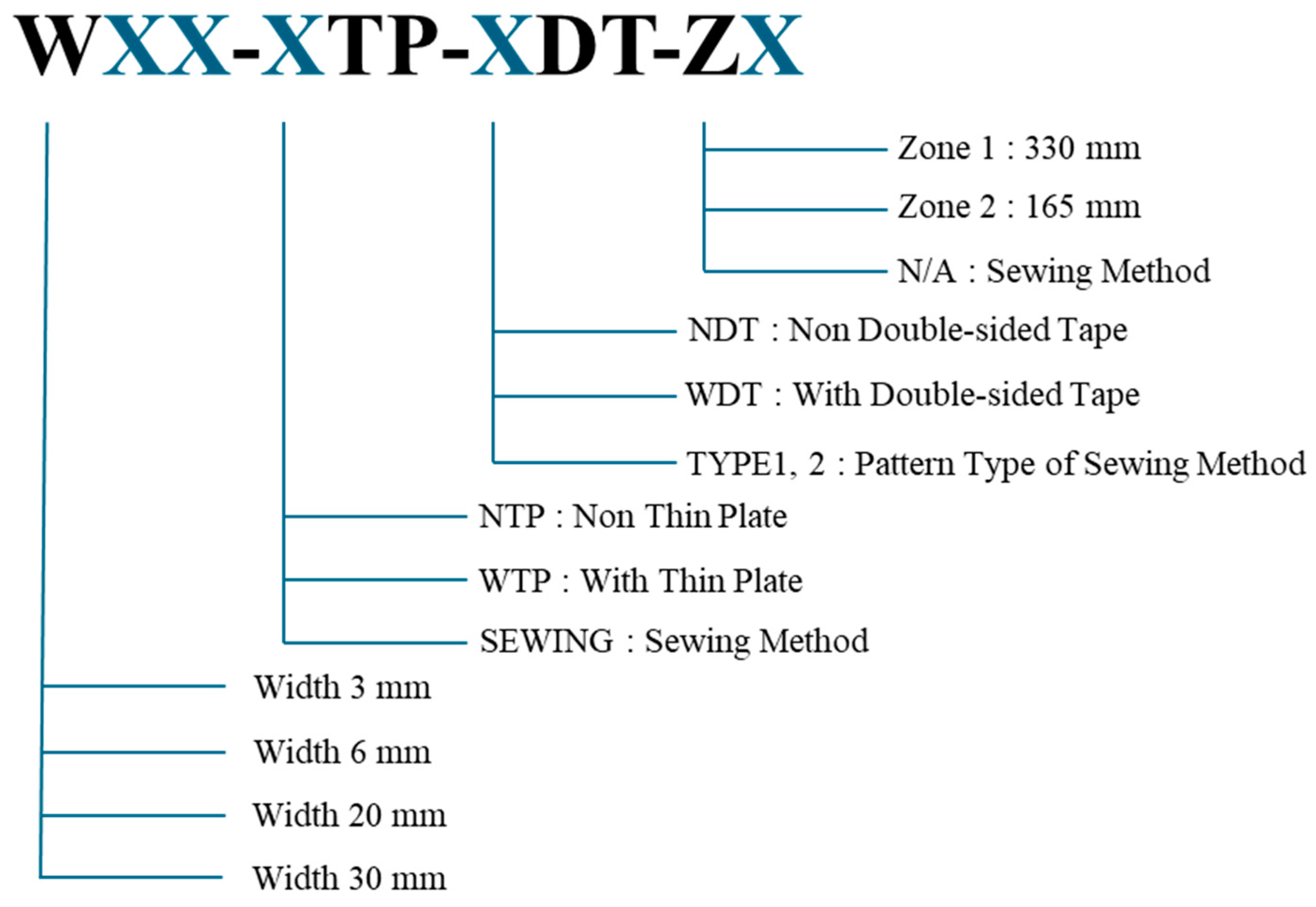
2.2. Design of the Clamping-Type Mesh Fastening Method

Figure 3 shows the configuration of the clamping-type mesh fastening method based on the antenna rib shape. The T-shaped rib is advantageous in terms of providing stiffness in ground tests, and the I-shaped rib is advantageous in terms of its light weight by minimizing its area. The proposed method was applied to each rib shape using the same process by placing a mesh fabric on the front of the antenna main reflector structure, overlaying it with a thin plate, and fastening it with push-button rivets. The components were manufactured using commercial materials to simulate mechanical characteristics instead of space-grade materials to verify the effectiveness of the proposed method. The thin plate was manufactured with a 0.6 mm thick FR4 material to ensure flexibility when placing it on curved surfaces, and commercially available nylon push-button rivets were used.
Push-button rivets operate on the same principle as ordinary metal rivets to fasten the thin plate and antenna structure, except that they do not cause permanent deformation. Metal rivets are mainly used in the aerospace field due to their lightweight and vibration-resistant characteristics compared to screws, bolts, and nuts. However, they have the disadvantage of being difficult to disassemble due to their permanent deformation. Push-button rivets were developed to overcome this disadvantage. They are made of a flexible material that temporarily deforms when inserted to provide a clamping force. This allows them to be easily disassembled and reused. In addition, they are secured by inserting them into the fastening interface within the plate and rib structure, providing the advantages of low labor complexity and improved ease of assembly. In the proposed method, the diameter of the rivets applied to each rib is 4 mm for the T-shaped rib and 3 mm for the I-shaped rib. In an idealized reflective surface of an analytically generated antenna, all areas would have uniform reflective properties. However, in practice, the areas where rivets are applied will inevitably affect the RF characteristics. Therefore, the smallest possible size rivets were applied to minimize this effect.
The proposed method consists of a thin plate with flexibility to maintain the curvature of the antenna rib structure. However, with a larger antenna size, there may be a gap between the thin plate and the antenna rib structure during fastening due to the increase in manufacturing errors between the components. The clamping-type method utilizes the friction between the thin plate and the mesh, which means that the gap in the structure causes a decrease in the clamping force and is disadvantageous in terms of maintaining the shape of the reflection surface. To solve the aforementioned problems, double-sided tape was applied to the mesh contact surface to compensate for manufacturing errors. The applied double-sided tape was 3M966 viscoelastic double-sided tape [19] with high shear adhesive strength, which is beneficial in terms of maintaining the shape of the fastening surface.

3. Experimental Validation of the Clamping-Type Fastening Method

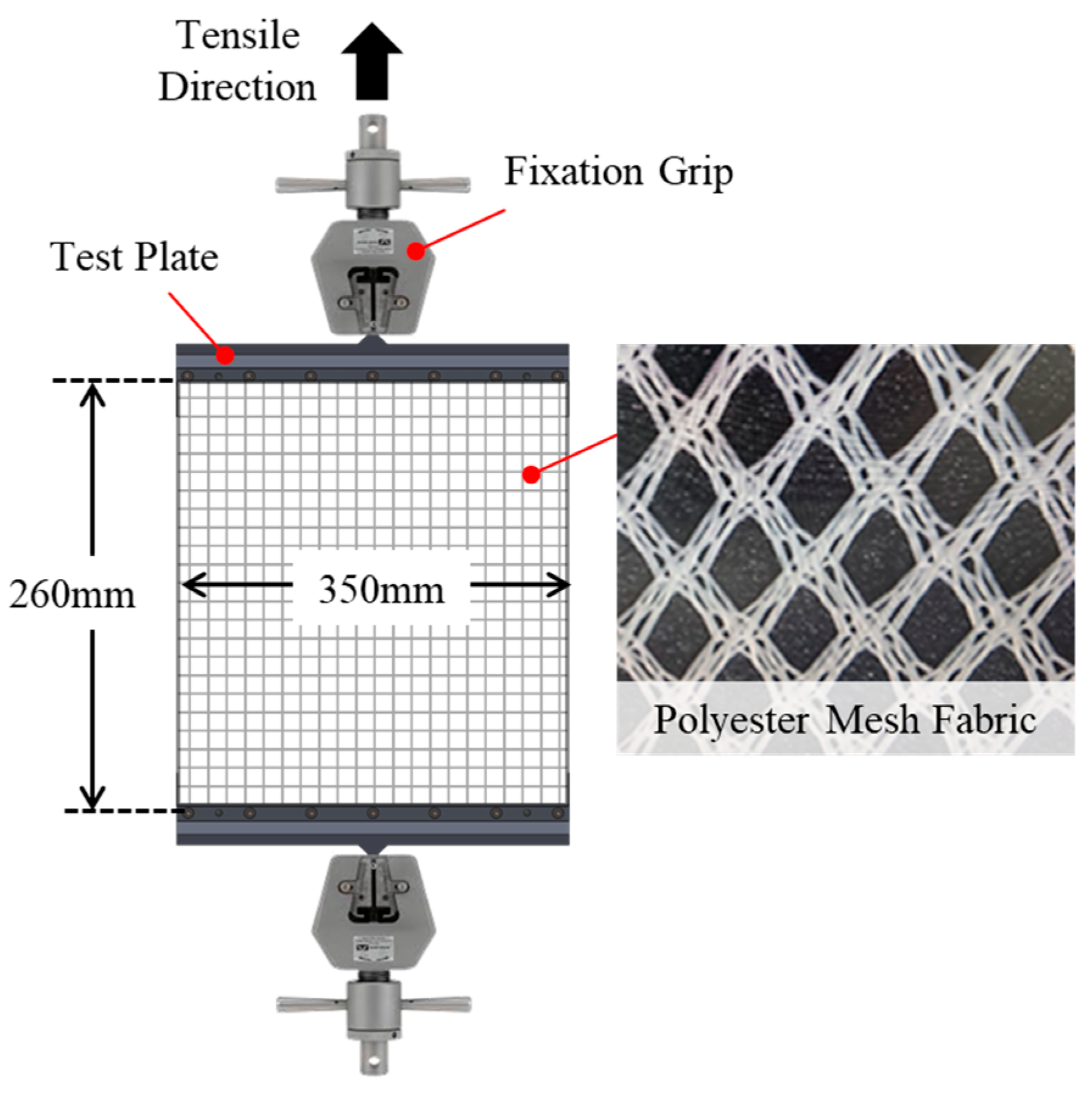
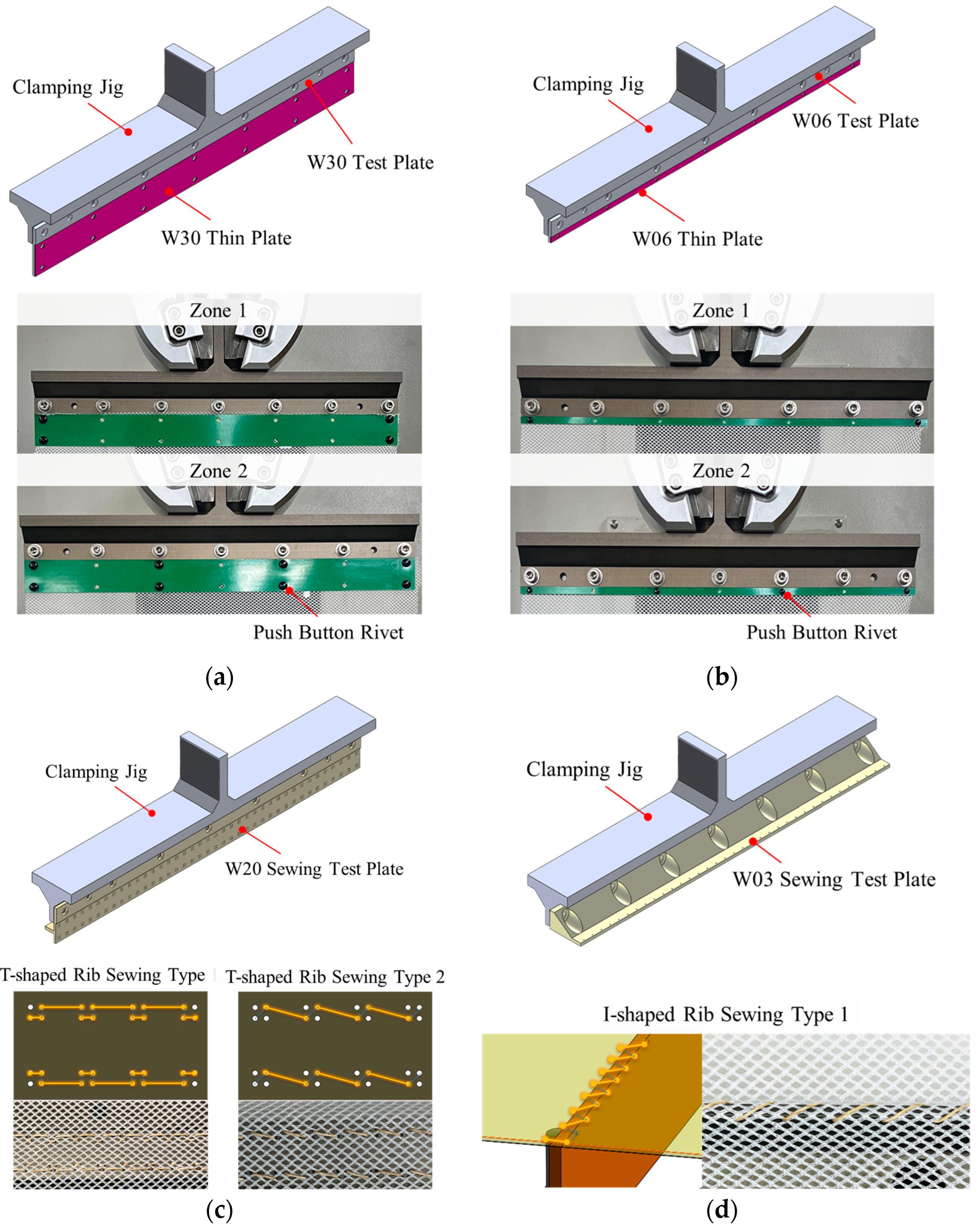
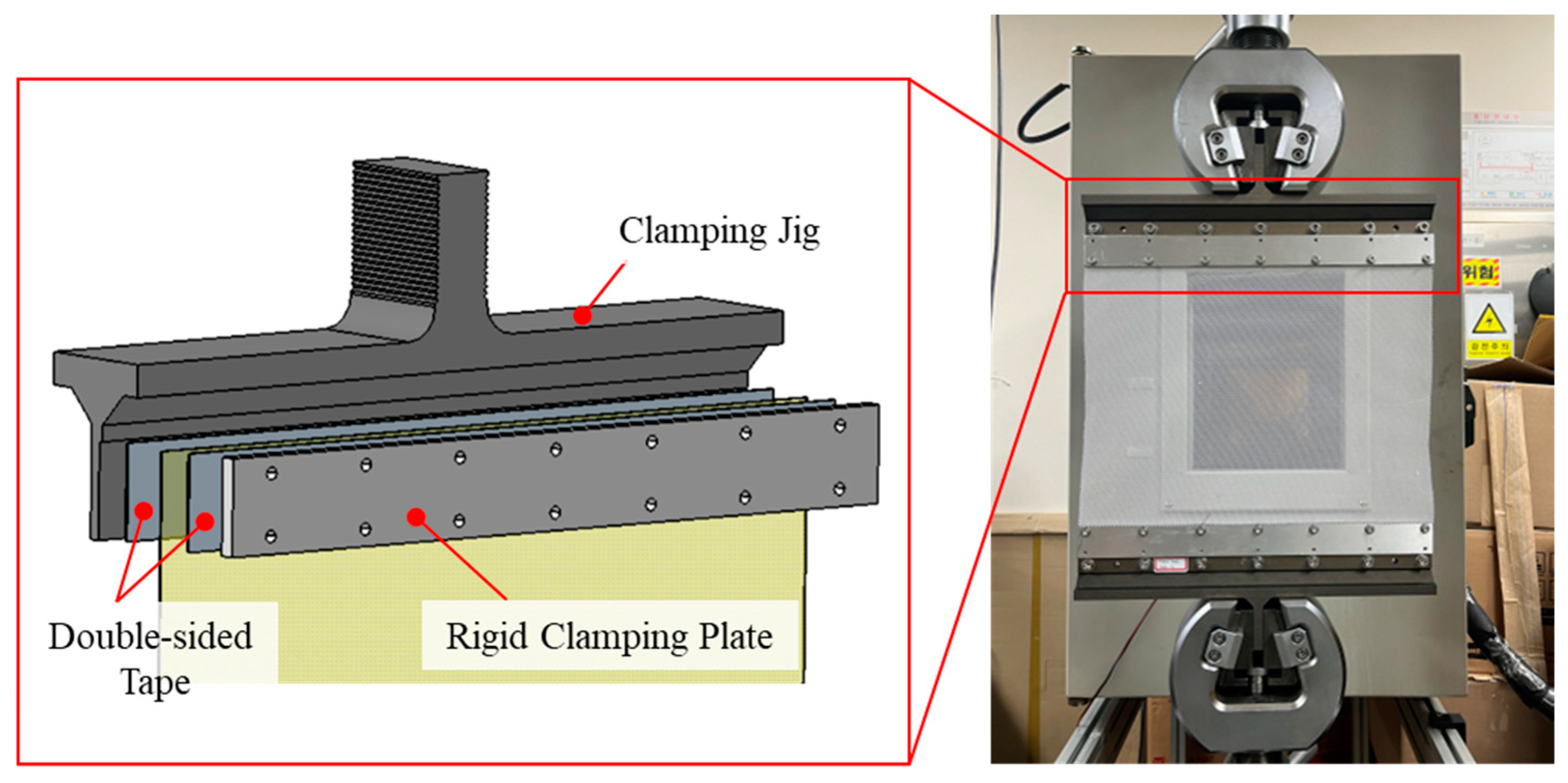
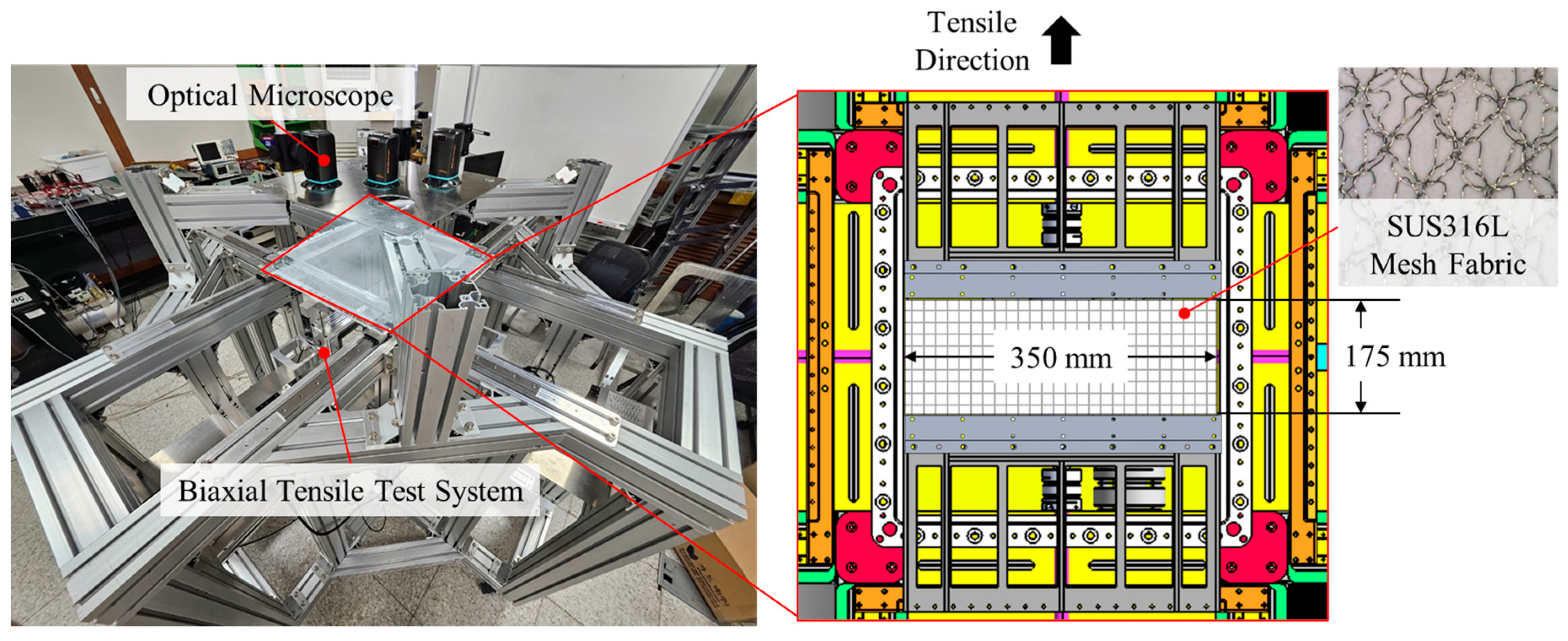
3.1. Tensile Strength Test Overview

Tensile strength tests were conducted to identify the optimal fastening method and validate its feasibility. The test conditions were mainly divided into two categories: T-shaped ribs and I-shaped ribs. These conditions were defined by the thin plate, viscoelastic double-sided tape, riveting point distance, and sewing method used for each rib type. Figure 4 shows the assignment method of the tensile strength test identifiers (IDs) based on the mesh fastening method, while Table 1 lists all tensile strength test cases. The fastening surface width of the clamping-type method was 30 mm for the T-shaped rib and 6 mm for the I-shaped rib, while the sewing method had a width of 20 mm for the T-shaped rib and 3 mm for the I-shaped rib. To analyze the effect of the riveting point distance in the clamping-type method, the distance was defined as 330 mm for zone 1 and 165 mm for zone 2. The presented riveting point distances were calculated using numerical analytical methods based on a previously studied 6 m deployable parabolic mesh antenna structure [20]. Equation (1) shows the numerical analytical method for the number of fastening points of a mesh antenna [21].
n r ϕ t Δ ϕ = sin 1 1 / 4 D / F 2 sin 1 15 4 δ r m s / D D / F
where n r represents the number of fastening points; ϕ t denotes the reflector angle; D is the reflector diameter; F is the focal length, and δ r m s refer to the surface root mean square (RMS) error of the reflector. Given that the reflector diameter and focal length are 6000 mm and 2100 mm, respectively, and assuming δ r m s to be 0.6, the requirement for the number of fastening points is calculated from Equation (1) to be at least 12. If the number of fastening points is assumed to be 20, considering the margin, the fastening point distance can be calculated as follows:
ϕ t = sin 1 D 4 F
l ¯ = 4 F sin Δ ϕ 2
where l ¯ denotes the riveting point distance, which is calculated 167 mm. The riveting point distance of 165 mm was selected as the initial test configuration to represent the above results, and a 330 mm test case was added to analyze the effect of riveting point distance.
The sewing method was categorized into three types based on the fastening shape. As no previous research clearly detailing a fastening process could be found, this study designed and presented a fastening shape capable of providing sufficient fastening force. For the sewing process, we used quartz fiber, which does not affect the RF characteristics of the antenna.
Figure 5 shows the tensile strength test setup. The test setup mainly consisted of a test plate, clamping jig, and polyester mesh fabric. After fastening the mesh fabric to the front of the test plate, it was assembled in the clamping jig and mounted on the tensile strength test equipment. The test plates were categorized based on the antenna rib shape and fastening method; the detailed configurations are shown in Figure 6. The main objective of the tensile strength test was to verify the feasibility of the proposed fastening method. Therefore, the mesh specimen used was a polyester mesh fabric with weaving and opening characteristics similar to those of metal mesh. The mesh pattern was atlas–atlas, and each specimen was manufactured to have a width of 350 mm and a length of 260 mm, excluding the contact surface area. The tensile strength testing equipment used included a universal testing machine (UTM) with a capacity of 10 kN to measure the load up to the tearing point of the mesh fabric under uniaxial loading. Each case was tested twice to ensure the reliability of the test data, and the average value was calculated.

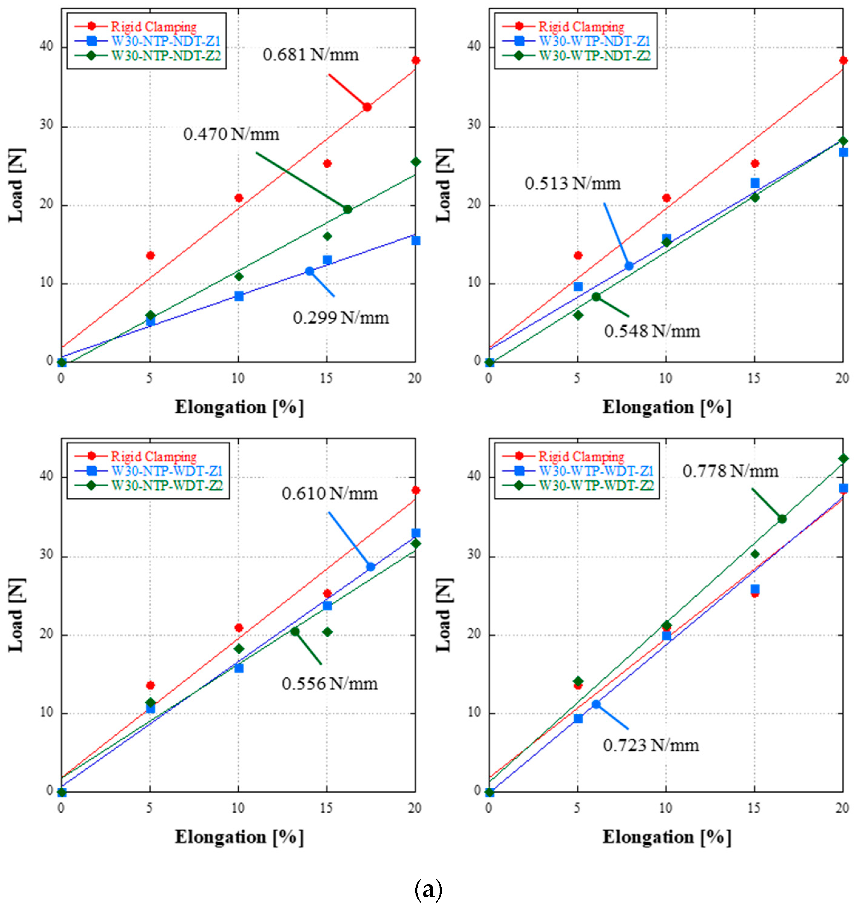
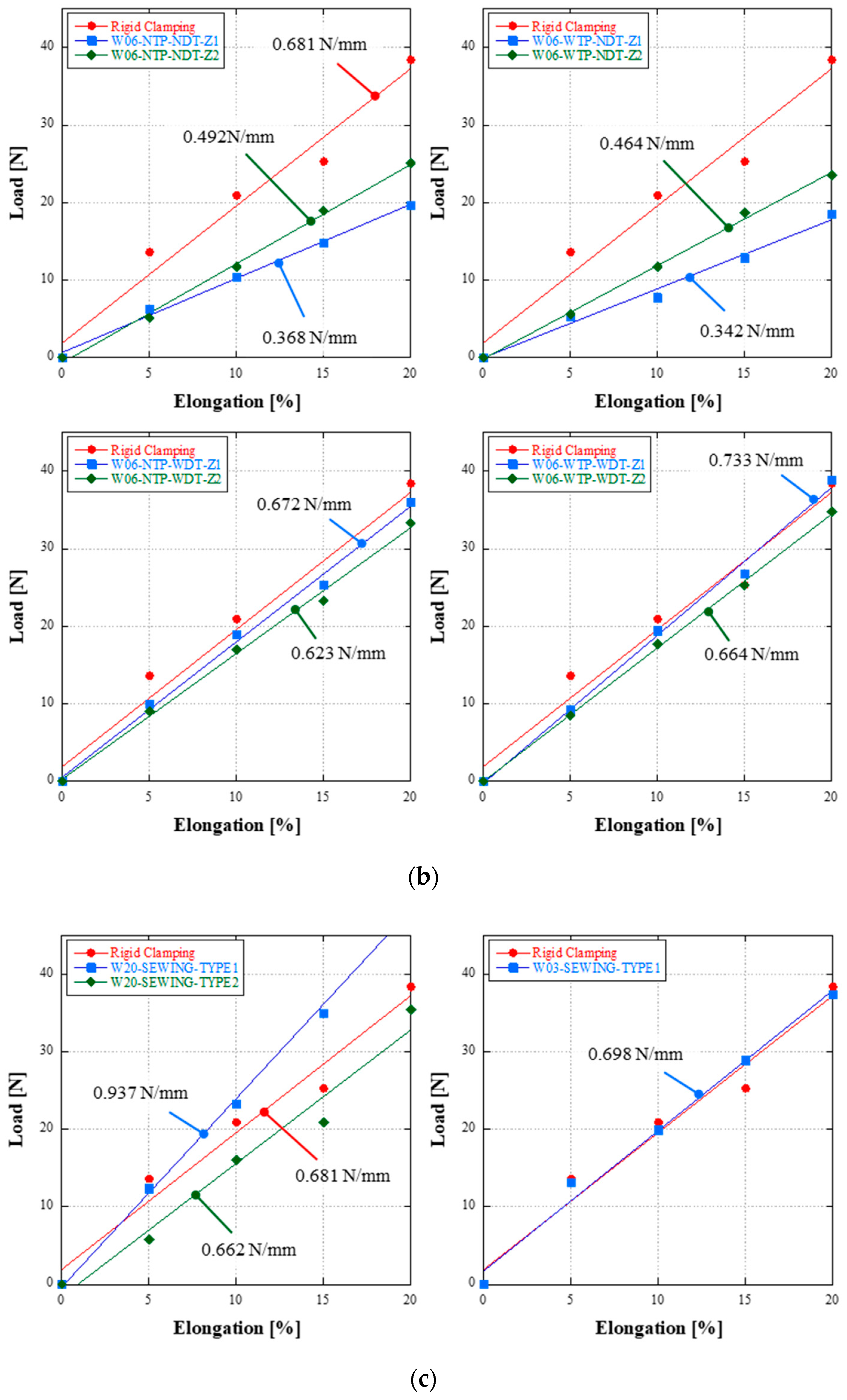
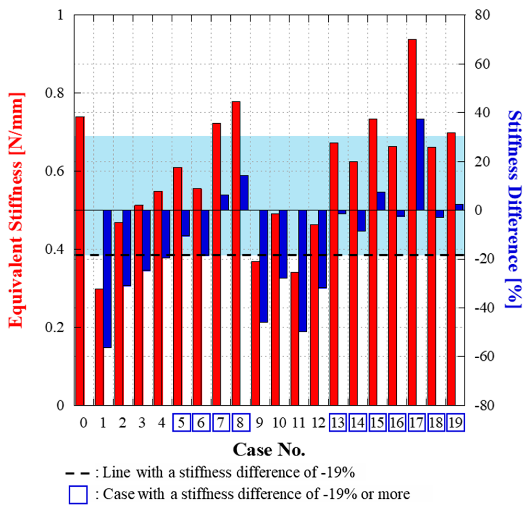
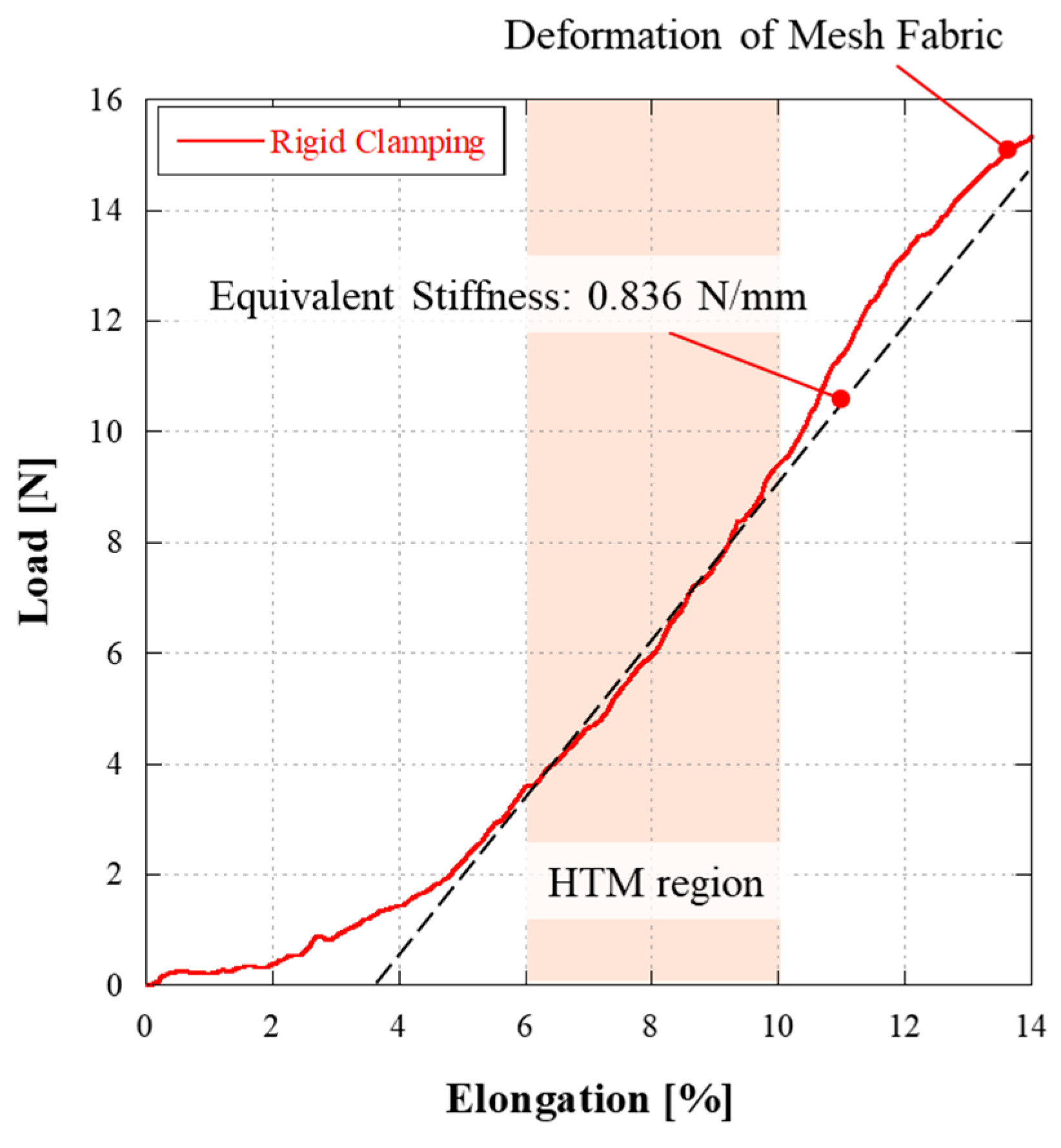
3.2. Tensile Strength Test Results

Figure 7 shows the test setup for the rigid clamping condition. The analysis criteria for the proposed fastening method were established based on the tensile strength test results under the rigid clamping condition with a strong fastening force. The rigid clamping condition was achieved by placing the mesh on the test plate and overlaying it with a 5 mm thick aluminum 6061 plate fastened with M5 fasteners. Viscoelastic double-sided tape was applied to the mesh contact surface to prevent slipping. The evaluation of the feasibility was conducted to determine whether the minimum required fastening force could be achieved, focusing on the LEM region, where the behavior is primarily influenced by the mesh pattern. The expected deformation of the mesh fabric in orbit is approximately 0.25%, which is significantly lower than the 20% elongation threshold defining the LEM region. Even under extreme launch conditions, displacement limitation mechanisms, such as launch locks, are typically implemented to ensure the structural integrity of the antenna structure. These mechanisms restrict excessive deformation of the mesh fabric, preventing it from exceeding the LEM region. Similarly, during ground deployment tests, additional mechanisms are applied to synchronize the deployment process and minimize the relative displacement of the ribs, ensuring that the deformation of the mesh fabric remains within the LEM region. Consequently, throughout the launch, on-orbit operation, and ground testing phases, the mesh fabric experiences deformation primarily within the LEM region, making this region the most appropriate focus for evaluating the feasibility of the fastening method. Therefore, by assessing the equivalent stiffness within the LEM region, this study ensures that the fastening method meets the required performance criteria under realistic operational conditions, effectively verifying its feasibility for deployable mesh antenna applications.
Figure 8 shows the tensile strength test results of the rigid clamping condition. The tensile strength test results of the rigid clamping condition show that the elongation below 20% corresponded to the LEM region, and an equivalent stiffness of 0.681 N/mm was obtained. These results were taken as reference data to evaluate the feasibility of each case.
Figure 9 shows the tensile strength test results and the calculated equivalent stiffness of each test case. To calculate the equivalent stiffness in the LEM region, linear regression using the least-squares method was applied to calculate the slope ( m ) of the data. The m was calculated as follows:
m = i = 1 n x i x ¯ y i y ¯ i = 1 n x i x ¯ 2
where x i and y i denote the respective data, and x ¯ and y ¯ are the mean values of the independent and dependent variables, respectively. m represents the linear relationship between the independent and dependent variables. In the calculation of the equivalent stiffness, the displacement was calculated by substituting the elongation of the mesh specimen size along the tensile direction.
In the case of the clamping-type fastening method for the T-shaped rib, the stiffness tended to increase when the thin plate was applied due to the reaction force caused by friction with the mesh fabric compared to the unapplied condition. However, the I-shaped rib had similar stiffness both with and without the thin plate, likely due to the smaller fastening area and a smaller number of rivets compared to the T-shaped rib. In addition, regardless of the rib shape, the tendency varied significantly depending on whether viscoelastic double-sided tape was used. Figure 10 shows the area where the slip occurred at the mesh fastening surface, and a comparison of the stiffness for each case is shown in Figure 11. In the case where a slip occurred at the contact surface of the mesh fabric during the tensile strength test, the stiffness decreased by more than 19.53% compared to the rigid clamping condition. Therefore, a mesh fastening method with a stiffness decrease of 19% or less is considered applicable. In the case without viscoelastic double-sided tape, the numerical results confirm that the stiffness tended to increase as the riveting point distance decreased. Nevertheless, when using only the push-button rivet for fastening, insufficient fastening force was provided at the contact surface. Even with the application of the thin plate to increase friction at the contact surface, slipping of the mesh fabric occurred, resulting in a significant decrease in stiffness. In the case of viscoelastic double-sided tape, the stiffness decreased by less than 19% compared to the rigid condition, even when fastened with only push-button rivets. In the case where both a thin plate and viscoelastic double-sided tape were applied, the stiffness was up to 14.24% higher than in the rigid clamping condition. Based on these results, the optimal fastening condition of the proposed clamping-type fastening method was identified as the case of applying both a thin plate and viscoelastic double-sided tape. The feasibility of this fastening method was verified as one that can prevent slip on the fastening surface. Furthermore, although the stiffness of the T-shape and I-shape was similar under optimal conditions despite differences in the fastening area, the I-shaped rib achieved approximately 42% mass reduction compared to the T-shaped rib for the same structural length, making it advantageous for lightweight design in deployable mesh antennas. The cross-sectional dimensions of each rib shape are shown in Figure 3, and based on these values, the cross-sectional area of the T-shaped rib is calculated to be 210 mm2 and the I-shaped rib to be 120 mm2. This corresponds to a 42% reduction in cross-sectional area, which is a direct indicator of mass reduction, assuming the same material properties and lengths.
For the sewing method, all types showed similar results to the rigid clamping condition. Even the T-shaped rib sewing type 2, which had the lowest stiffness, showed a stiffness degradation of less than 8%. In particular, the T-shaped rib sewing type 1 showed a 37.59% increase in stiffness compared to the rigid clamping condition. This is believed to be due to the high fastening force applied to the mesh fabric by all openings sewn along the fastening line, in contrast to other fastening types.
A summary of the tensile strength test results is listed in Table 2. Based on the tensile strength test results, the sewing method has an advantage over the clamping-type fastening method in terms of securing the fastening force. However, it has high work difficulty, as it requires maintaining consistent intervals that depend on the size of the openings and ensuring proper tension in the fastening wire and mesh. In addition, due to the assembly sequence of the mesh antenna, where the mesh must be fastened after the main reflector structure is assembled, there is a disadvantage: as the antenna size and the operating frequency band increase, both the work difficulty and the time required for assembly increase significantly. On the other hand, the clamping-type mesh fastening method results in a similar stiffness as that of the sewing method, and it is superior in terms of workability due to its shorter working time and simple application process, which does not require high expertise.

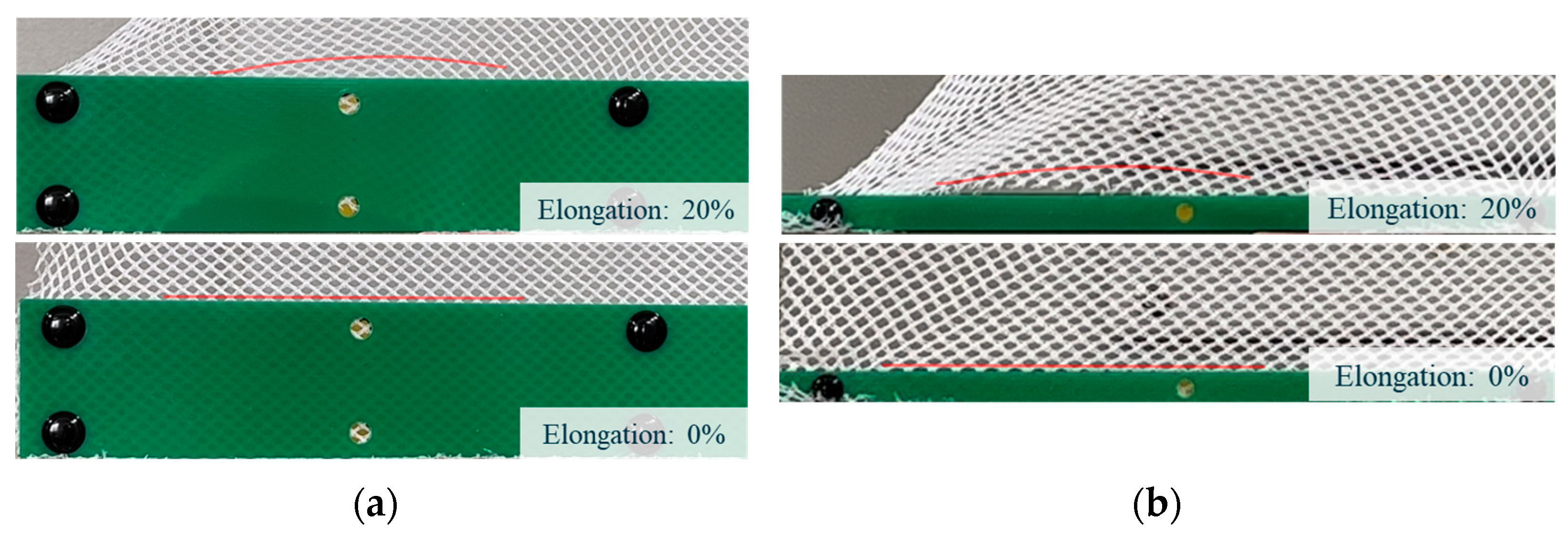
3.3. Repeated Tensile Test Overview

A verification test under repeated tensile conditions was conducted to identify the optimal fastening method based on the results of the tensile strength tests. The optimal fastening method was determined to be applying both a thin plate and viscoelastic double-sided tape. This analysis was performed according to the rib shape and riveting point distance. Figure 12 shows the repeated tensile test setup. The test equipment was modified from a biaxial tensile test system, which can apply tension to all four sides of the mesh simultaneously to allow for repeated uniaxial tensioning. An optical microscope was applied at the top of the test equipment to measure changes in the OPI and the shape of the openings in the mesh specimens under tension. The main purpose of the repeated tensile test was to determine whether a slip occurred at the fastening surface in the HTM region, where the fastening point was highly stressed within the elastic region of the mesh fabric. Results were obtained by performing five tensile tests continuously. The results show that slippage occurs in the first cycle of the repeated tensile test if sufficient fastening force is not provided, as suggested by the tensile strength test. This phenomenon is more easily occurring in the HTM region. Therefore, the effectiveness of the fastening method was evaluated based on the results of five repeated tensile tests. The mesh specimens were manufactured from stainless steel 316L (SUS316L) mesh fabric woven in an atlas–atlas pattern. Each specimen was fabricated to a width of 350 mm and a length of 175 mm, excluding the contact surface area.

3.4. Repeated Tensile Test Results

The analysis criteria for the repeated tensile tests were established based on the test results under the rigid clamping condition, similar to those used for the tensile strength tests. Figure 13 shows the SUS316L mesh fabric tensile test results under the rigid clamping condition at an elongation of 14%. The results of the rigid clamping condition test show that the mesh fabric deformed at an elongation of 14%. Therefore, the maximum tensile condition was determined at an elongation of 10%.
Figure 14 shows the changes in the OPI and the openings of the mesh fabric based on elongation. The data obtained during the repeated tensile tests under the rigid clamping condition show a decrease in the OPI and an expansion of the openings at an elongation above 5%. The fastening force was analyzed based on the stiffness of the HTM region, and an elongation of 6–10% was determined as the range for comparing the stiffness based on the above results.
To determine whether slip occurred on the mesh fastening surface of the proposed method, the standard deviation of the load obtained from five repeated tests was calculated. The mean ( x ¯ ) of the acquired data was calculated as follows:
x ¯ = 1 n i = 1 n x i
Then, the standard deviation ( s ) was calculated as follows:
s = 1 n 1 i = 1 n x i x ¯ 2
Figure 15 shows the standard deviation ( s ) of the load based on the elongation obtained from the five repeated tensile tests. The maximum deviation of 0.33 N under the rigid clamping condition, which provided a strong fastening force without slip, was insignificant at 3.5% of the maximum load. This is considered to be noise in the test equipment. The maximum deviation of the proposed fastening method was 0.28 N, which is similar to that observed under the rigid clamping condition. Therefore, these results verify that the proposed fastening method is capable of preventing slip in the HTM region.
Figure 16 shows the results of the repeated tensile tests based on the shape of the ribs, and the equivalent stiffnesses for five repetitions in the HTM region were calculated using Equation (4). In the LEM range of 0–4% elongation, the proposed clamping-type fastening method showed results similar to those of the tensile strength test, which exceeded the stiffness observed under the rigid clamping condition. However, in the HTM region, the T-shaped rib method exhibited a stiffness decrease of up to 17.11%, while the I-shaped rib method showed a decrease of up to 5.14% compared to the rigid clamping condition. The test results indicate that the proposed fastening method demonstrated a gradual difference in stiffness between the LEM and HTM regions compared to the rigid clamping condition. This behavior was caused by the mesh contact surface being attached with viscoelastic double-sided tape. As the mesh fabric deformed, partial deformation occurred on the adhesive side, which underwent a lower clamping force compared to the riveting point. This behavior is also evident in the results of the I-shaped rib clamping-type method test, where the fastening force of the thin plate and push-button rivets was relatively low due to the small clamping area. Based on the trend of the stiffness changing slightly as the riveting point distance decreased, it can be confirmed that the fastening force of the viscoelastic double-sided tape was dominant. The absence of slip during the five repeated tests is attributed to the resilience of the viscoelastic double-sided tape, which can return to its initial shape when a tensile load is removed, even after partial deformation occurs.
Slip may occur as displacement increases when the proposed fastening method is used. However, this test was conducted within the elastic region of the mesh fabric, and any larger displacements would cause permanent deformation of the fabric. Therefore, the proposed fastening method can provide sufficient fastening force for SUS316L mesh fabric. These results verify the effectiveness of the proposed method.

4. Conclusions

In this study, a clamping-type fastening method using a thin plate and push-button rivets is proposed, and its effectiveness was experimentally verified. The proposed method is divided into two types, T-shape and I-shape, based on the shape of the antenna rib. The method of fastening by overlaying a thin plate on the front of the antenna rib structure has the advantage of distributing the stresses acting on the mesh and maintaining the curvature of the reflection surface due to its wide fastening surface, compared to the conventional sewing method. Furthermore, it allows for high workability with a simple work process.
Tensile strength tests were conducted to verify the feasibility of the proposed method. The test results show that the optimal fastening method was identified as using both a thin plate and double-sided tape. When applying the optimal fastening method, the I-shaped rib fastening method exhibited similar stiffness as the T-shaped rib despite having a smaller fastening area. The results indicate that the I-shaped rib fastening method is advantageous for mass reduction during the antenna design process. Although the proposed fastening method exhibited lower stiffness than the sewing method, the difference is expected to be maximized with increasing antenna sizes due to its higher workability.
The effectiveness of the identified optimal clamping technique was verified through repeated tensile tests. The main purpose of this test was to verify the fastening force and compare the stiffness of the HTM section to that of the rigid clamping condition. Data showing the same trend were obtained without slippage at the mesh fastening surface during a total of five repeated tensile tests for each case. The above results verify that it is possible to provide sufficient clamping force at the mesh fastening surface without slippage.

Author Contributions

Conceptualization, H.-U.O.; methodology, H.-U.O. and B.-G.C.; validation, J.-S.C. and B.-G.C.; formal analysis, J.-S.C. and H.-U.O.; investigation, J.-S.C.; data curation, J.-S.C. and B.-G.C.; writing—original draft preparation, J.-S.C.; writing—review and editing, J.-S.C. and H.-U.O.; visualization, J.-S.C. and H.-U.O.; supervision, H.-U.O.; project administration, H.-U.O. and B.-G.C.; funding acquisition, H.-U.O. All authors have read and agreed to the published version of the manuscript.

Funding

This research was financially supported by the Institute of Civil–Military Technology Cooperation, funded by the Defense Acquisition Program Administration and the Ministry of Trade, Industry, and Energy of the Korean government under grant No. 22-CM-EC-32.

Data Availability Statement

The data presented in this study are available upon request from the corresponding author.

Conflicts of Interest

Authors Bong-Geon Chae and Hyun-Ung Oh were employed by the company STEP Lab. Ltd. The remaining author declares that this research was conducted in the absence of any commercial or financial relationships that could be construed as potential conflicts of interest.

References

  1. The Newspace Paradigm: SpaceX Is Just the Beginning. Available online: http://trinitamonti.org/2020/07/15/the-newspace-paradigm-spacex-is-just-the-beginning/ (accessed on 30 December 2024).
  2. Zancan, V.; Paravano, A.; Locatelli, G.; Trucco, P. Evolving governance in the space sector: From legacy space to new space models. Acta Astronaut. 2024, 225, 515–523. [Google Scholar] [CrossRef]
  3. Lappas, V.; Kostopoulos, V. A survey on small satellite technologies and space missions for geodetic applications. In Satellite Missions and Technologies for Geosciences; IntechOpen: London, UK, 2020; Volume 8, pp. 123–144. [Google Scholar]
  4. Ince, F. Nano and micro satellites as the pillar of the “new space” paradigm. J. Aeronaut. Space Technol. 2020, 13, 235–250. [Google Scholar]
  5. Logue, T.J.; Pelton, J. Overview of commercial small satellite systems in the “new space” age. In Handbook of Small Satellites; Springer Nature: Berlin/Heidelberg, Germany, 2019. [Google Scholar]
  6. Rahmat-Samii, Y.; Manohar, V.; Kovitz, J.M.; Hodges, R.E.; Freebury, G.; Peral, E. Development of highly constrained 1m Ka-band mesh deployable offset reflector antenna for next generation CubeSat radars. IEEE Trans. Antennas Propag. 2019, 67, 6254–6266. [Google Scholar] [CrossRef]
  7. Rao, S.; Shafai, L.; Sharma, S. Handbook of Reflector Antennas and Feed Systems Volume III: Applications of Reflectors; Artech: London, UK, 2013. [Google Scholar]
  8. Focardi, P.; Brown, P.R.; Rahmat-Samii, Y. Deployable mesh reflector antennas for space applications: RF characterizations. In Space Antenna Handbook; John Wiley & Sons: Hoboken, NJ, USA, 2012. [Google Scholar]
  9. Lopatin, A.V.; Morozov, E.V.; Kazantsev, A.; Berdnikova, N.A. Deployment analysis of a composite thin-walled toroidal rim with elastic hinges: Application to an umbrella-type reflector of spacecraft antenna. Compos. Struct. 2023, 306, 116566. [Google Scholar] [CrossRef]
  10. Zhang, Y.; Zhang, H.; Yang, D. Form-finding design of cable-mesh deployable reflector antennas considering wire mesh properties. AIAA J. 2019, 57, 5027–5041. [Google Scholar] [CrossRef]
  11. Goddard Space Flight Center. Final Report for ATS F&G. Available online: https://ntrs.nasa.gov/api/citations/19710001365/downloads/19710001365.pdf (accessed on 30 December 2024).
  12. Lockheed Missiles & Space Company, Inc. Method of Attaching Antenna Mesh. Available online: https://patentimages.storage.googleapis.com/3c/c0/68/2e64b91bba0518/US5456779.pdf (accessed on 30 December 2024).
  13. Thomson, M.W. Mechanical vs. Inflatable Deployable Structures for Large Apertures or Still No Simple Answers. In Proceedings of the Large Space Apertures Workshop California Institute of Technology, Pasadena, CA, USA, 10–11 November 2008. [Google Scholar]
  14. Bettermann, I.; Löcken, H.; Greb, C.; Gries, T.; Oses, A.; Pauw, J.; Maghaldadze, N.; Datashvili, L. Review and evaluation of warp-knitted patterns for metal-based large deployable reflector surfaces. CEAS Space J. 2023, 15, 477–493. [Google Scholar] [CrossRef]
  15. Scialino, G.L.; Salvini, P.; Migliorelli, M.; Pennestri, E.; Valentini, P.P.; van’t Klooster, K.; Santiago-Prowald, J.; Rodrigues, G.; Gloy, Y. Structural characterization and modeling of metallic mesh material for large deployable reflectors. In Proceedings of the 2nd International Conference: Advanced Lightweight Structures and Reflector Antennas, Tbilisi, Georgia, 1–3 October 2014; pp. 182–192. [Google Scholar]
  16. Mueller, K.M.A.; Mulderrig, S.; Najafian, S.; Hurvitz, S.B.; Sodhani, D.; Mela, P.; Stapleton, S.E. Mesh manipulation for local structural property tailoring of medical warp-knitted textiles. J. Mech. Behav. Biomed. Mater. 2022, 128, 105117. [Google Scholar] [CrossRef] [PubMed]
  17. Hasan, A.; Ragaert, K.; Swieszkowski, W.; Selimović, Š.; Paul, A.; Camci-Unal, G.; Mofrad, M.R.K.; Khademhosseini, A. Biomechanical properties of native and tissue engineered heart valve constructs. J. Biomech. 2014, 47, 1949–1963. [Google Scholar] [CrossRef] [PubMed]
  18. Ma, Y.; Feng, X.; Rogers, J.A.; Huang, Y.; Zhang, Y. Design and application of ‘J-shaped’ stress-strain behavior in stretchable electronics: A review. Lab Chip. 2017, 17, 1689–1704. [Google Scholar] [CrossRef] [PubMed]
  19. 3MTM Adhesive Transfer Tape 966. Available online: https://multimedia.3m.com/mws/media/2365951O/3m-adhesive-transfer-tape-966.pdf?&fn=3M-Adhesive-Transfer-Tape-966_R1.pdf (accessed on 30 December 2024).
  20. Choi, J.S.; Park, T.Y.; Chae, B.G.; Oh, H.U. Development of lightweight 6 m deployable mesh reflector antenna mechanisms based on superelastic shape memory alloy. Aerospace 2024, 11, 738–759. [Google Scholar] [CrossRef]
  21. Shi, H.; Yuan, S.; Yang, B. New methodology of surface mesh geometry design for deployable mesh reflectors. J. Spacecr. Rocket. 2018, 55, 266–281. [Google Scholar] [CrossRef]
Figure 1. Examples of mesh weave patterns: (a) tricot mesh, (b) atlas mesh, (c) atlas–atlas mesh.
Aerospace 12 00248 g001
Figure 2. J-shaped stress–strain curve of soft tissues.
Aerospace 12 00248 g002
Figure 3. Configurations of the clamping-type mesh fastening method: (a) T-shaped rib; (b) I-shaped rib.
Aerospace 12 00248 g003
Figure 4. ID assignment method for tensile strength test using mesh fastening methods.
Aerospace 12 00248 g004
Figure 5. Tensile strength test setup.
Aerospace 12 00248 g005
Figure 6. Configuration of each mesh fastening method: (a) clamping-type method for T-shaped rib; (b) clamping-type method for I-shaped rib; (c) sewing method for T-shaped rib; (d) sewing method for I-shaped rib.
Aerospace 12 00248 g006
Figure 7. Rigid clamping condition test setup.
Aerospace 12 00248 g007
Figure 8. Tensile strength test result of the rigid clamping condition.
Aerospace 12 00248 g008
Figure 9. Tensile strength test results of each case: (a) clamping-type method for T-shaped rib; (b) clamping-type method for I-shaped rib; (c) sewing method.
Aerospace 12 00248 g009aAerospace 12 00248 g009b
Figure 10. Shapes of slip at mesh fastening surfaces: (a) case 4; (b) case 12.
Aerospace 12 00248 g010
Figure 11. Comparison of the stiffness for each case.
Aerospace 12 00248 g011
Figure 12. Repeated tensile test setup.
Aerospace 12 00248 g012
Figure 13. SUS316L mesh fabric tensile test results of rigid clamping condition at elongation of 14%.
Aerospace 12 00248 g013
Figure 14. OPI and opening changes in mesh fabric based on elongation.
Aerospace 12 00248 g014
Figure 15. Standard deviation values of load based on elongation.
Aerospace 12 00248 g015
Figure 16. Repeated tensile test results of each case: (a) T-shaped rib, (b) I-shaped rib.
Aerospace 12 00248 g016
Table 1. Summary of tensile strength test cases.
CaseTest ID
1W30-NTP-NDT-Z1
2W30-NTP-NDT-Z2
3W30-WTP-NDT-Z1
4W30-WTP-NDT-Z2
5W30-NTP-WDT-Z1
6W30-NTP-WDT-Z2
7W30-WTP-WDT-Z1
8W30-WTP-WDT-Z2
9W06-NTP-NDT-Z1
10W06-NTP-NDT-Z2
11W06-WTP-NDT-Z1
12W06-WTP-NDT-Z2
13W06-NTP-WDT-Z1
14W06-NTP-WDT-Z2
15W06-WTP-WDT-Z1
16W06-WTP-WDT-Z2
17W20-SEWING-TYPE1
18W20-SEWING-TYPE2
19W03-SEWING-TYPE1
Table 2. Summary of tensile strength test results.
CaseTest IDEquivalent Stiffness
[N/mm]
Rib
Shape
Riveting Distance
[mm]
Remark
Ref.Rigid Clamping0.681---
1W30-NTP-NDT-Z10.470T-shaped 330w/o Thin Plate
w/o Double-sided Tape
2W30-NTP-NDT-Z20.299165w/o Thin Plate
w/o Double-sided Tape
3W30-WTP-NDT-Z10.513330w/Thin Plate
w/o Double-sided Tape
4W30-WTP-NDT-Z20.548165w/Thin Plate
w/o Double-sided Tape
5W30-NTP-WDT-Z10.610330w/o Thin Plate
w/Double-sided Tape
6W30-NTP-WDT-Z20.556165w/o Thin Plate
w/Double-sided Tape
7W30-WTP-WDT-Z10.723330w/Thin Plate
w/Double-sided Tape
8W30-WTP-WDT-Z20.778165w/Thin Plate
w/Double-sided Tape
9W06-NTP-NDT-Z10.368I-shaped 330w/o Thin Plate
w/o Double-sided Tape
10W06-NTP-NDT-Z20.492165w/o Thin Plate
w/o Double-sided Tape
11W06-WTP-NDT-Z10.342330w/Thin Plate
w/o Double-sided Tape
12W06-WTP-NDT-Z20.464165w/Thin Plate
w/o Double-sided Tape
13W06-NTP-WDT-Z10.672330w/o Thin Plate
w/Double-sided Tape
14W06-NTP-WDT-Z20.623165w/o Thin Plate
w/Double-sided Tape
15W06-WTP-WDT-Z10.733330w/Thin Plate
w/Double-sided Tape
16W06-WTP-WDT-Z20.664165w/Thin Plate
w/Double-sided Tape
17W20-SEWING-TYPE10.937T-shaped -Sewing Method
18W20-SEWING-TYPE20.662-Sewing Method
19W03-SEWING-TYPE10.698I-shaped -Sewing Method
Disclaimer/Publisher’s Note: The statements, opinions and data contained in all publications are solely those of the individual author(s) and contributor(s) and not of MDPI and/or the editor(s). MDPI and/or the editor(s) disclaim responsibility for any injury to people or property resulting from any ideas, methods, instructions or products referred to in the content.

