Article

The Assembly, Integration and Test of the DORA Telescope, a Deployable Optics System in Space for Remote Sensing Applications

1
INAF-IAPS, Institute for Space Astrophysics and Planetology, Tor Vergata Via del Fosso del Cavaliere 100, 00133 Rome, Italy
2
Department of Industrial Engineering, University of Padua, Via Venezia 1, 35131 Padua, Italy
*
Author to whom correspondence should be addressed.
Aerospace 2025, 12(3), 224; https://doi.org/10.3390/aerospace12030224
Submission received: 13 January 2025 / Revised: 25 February 2025 / Accepted: 5 March 2025 / Published: 10 March 2025
(This article belongs to the Section Astronautics & Space Science)

Abstract

:
The paper deals with the assembling, integration, and test (AIT) phase of the laboratory model of an innovative telescope in the framework of the project DORA (deployable optics for remote sensing applications). The telescope is a Cassegrain type of instrument, with an entrance pupil of ∅300 mm, f/16 aperture, and FOV of 0.16°. It has been designed to be mounted onboard a micro-satellite frame, allowing for switching between a stowed configuration during the launch phase and a deployed one once in orbit. The telescope is matched to an infrared Fourier spectrometer, operating in the spectral range of 5–25 μ m, for the observation of terrestrial atmospheric phenomena, but it can also be adopted for planetary exploration missions. The telescope breadboard has been assembled in the INAF-IAPS premises and has undergone measurements for the determination of the accuracy and repeatability of the mechanism opening. The mechanical tests have demonstrated that the deployment mechanism adopted complies with the requirements imposed by the infrared Fourier spectrometer, guaranteeing a repositioning of the secondary mirror with respect to the primary mirror within 100 μ m (in-plane displacement) and 0.01° (tilt) of the nominal position.

1. Introduction

In the last few years, there has been an exponential growth of interest in small platforms in space, and this is based on several arguments. On one hand, small platforms allow for a reduction in the costs of an Earth Observing program devoted to the monitoring and control of the environment, making it economically affordable for nations, communities, and private companies without direct access to space. Additionally, they ease the possibility of using distributed systems in space, making use of more satellites flying in formation or as a constellation, for instance, to increase the temporal resolution for the observation of quasi-transient phenomena in local areas. On the other hand, remote sensing instrumentation (cameras and spectrometers) requiring high spatial resolution is quite demanding in terms of volume and mass. Indeed, large entrance pupils and long focal lengths represent a challenge for mini and micro-satellites. The identification of payloads capable of minimizing resource usage at launch, while still guaranteeing in-flight performance analogous to that of more “expensive” instruments, in terms of resources, is an extremely valuable benefit. Precision-deployable, stable optical telescopes that fit inside smaller, lower-cost launch vehicles and small platforms are a prime example of a technology that will yield breakthrough benefits for future scientific as well as more commercially oriented applications [1]. Furthermore, as pointed out by [2], micro- and nano-satellites are essential for exploiting cutting-edge technologies intended for future space missions. It then becomes natural to envisage projects that develop technology for deployable structures onboard small satellites.
The DORA (deployable optics for remote sensing applications) project was submitted to the Italian Ministry of Research and was funded within the framework of the Italian National Research Infrastructure Plan 2015–2020. It involved collaboration among several research institutes (INAF-IAPS, the Institute for Space Astrophysics and Planetology in Rome, and INAF-OAPD, Padua Astronomical Observatory), academic centers (Naples University “Parthenope” and Politecnico of Milan), and companies (SITAEL S.p.A., the largest Italian company in space technology, Steam S.r.l., and KAD 3 S.r.l.).
The major objective we wanted to achieve with this project was to design, build, and test a laboratory model of a deployable telescope to validate the technology involved, reaching a TRL4 (Breadboard validation in a laboratory environment). In addition, to demonstrate the capability of using this telescope for Earth observations, we studied its interface with the single-pixel Fourier transform IR (FTIR) spectrometer MIMA (Mars Infrared MApper), which is a double pendulum interferometer [3] available as an engineering model in INAF-IAPS premises, and we designed a suitable Earth observing mission using a small platform. The MIMA spectrometer, designed and developed in the framework of the ESA’s ExoMars mission, provides spectra in the 5–25 μ m wavelength range, with a resolving power of 1000 at 2 μ m and 80 at 25 μ m (more details about the thermomechanical and optical design featuring the Fourier spectrometer are given [4,5]); however, since it was designed to be ground mounted on a rover, it does not have any foreoptics. Therefore, the DORA telescope design had to be adjusted to match the MIMA field of view (FOV) for operation from orbit and to ensure the scientific objectives were met. The use of a FTIR with its single pixel of 1 mm × 1 mm [5] simplifies the design, construction, and testing of the deployable telescope. Both the telescope and MIMA were to be mounted onboard a microsatellite platform (SITAEL S-75) for a LEO mission scenario at 500–550 km altitude for Earth observation. The DORA scientific objectives were devoted to Earth remote observations (EO) for ecological and environmental purposes [6] and, more specifically, for the detection and study of the spatial and temporal distribution of several of Earth’s atmospheric pollutant molecules as well as for the detection and monitoring of wildfires. In addition, such an instrument would be very useful for investigating planetary and small Solar System bodies, to study the composition of the Martian atmosphere or to study the near-Earth Asteroids’ composition, dimension, and structure [3,7].
A number of projects propose different solutions for deployable space optics to be hosted by micro- and nano-satellites, and we refer the reader to a recent paper [8] for a comprehensive overview. However, most of the deployable systems proposed so far are made up of segmented primary mirrors, which, although most effective in minimizing the volume at launch, require very stringent tolerances for nominal positioning of the actuated segments, which is in the order of λ /20; furthermore, they need active positioning systems that are used to correct the alignment during observations. The DORA telescope is instead composed of a 300 mm monolithic primary mirror, which allows us to overcome the limitations of the segmented mirrors, strongly simplifying the design, and the volume saving is achieved by deploying the secondary mirror using a collapsible system. The novelty of the DORA telescope lies in the deployment mechanism. In particular, the selection of the specific collapsible system for the DORA telescope has been the object of a trade-off study summarized in [9], where five different configurations have been studied, and the adopted solution has been chosen as the one that guarantees the best performance in mass saving, compactness, and lack of FOV obscuration.
It must be mentioned that a deployable telescope with the DORA specifications can be very appealing for a number of remote sensing applications, including imaging spectrometers (in the VIS and IR) and imaging cameras, albeit with more challenging constraints in terms of the accuracy of the position of the secondary mirror.
In Section 2, we describe the mission requirements as imposed by the selected spacecraft; in Section 3, we briefly describe the telescope and instrument optical design and derive the maximum positioning errors that must be achieved by the deployment mechanism to guarantee mechanical alignment of the telescope. Section 4 summarizes the mechanical design of the telescope (described in detail elsewhere) and the design of the supporting structure built to firmly hold the telescope while actuating. Section 5 and Section 6 describe, respectively, the mechanical assembly procedure and the full test and analysis work.

2. Mission Requirements

The deployable telescope developed within the DORA project has been adapted to the housing requirements of the SITAEL S-75 microsatellite platform (75 kg), where the allowed envelope payload is 320 × 320 × 400 mm3. The S-75 is capable of carrying a P/L in a LEO mission scenario at a 500–550 km altitude with a mass lower than 25 kg and a power of 35W (peak consumption less than 200 W).
Given the available volume, the instrument (FTIR plus telescope) in its stowed configuration shall be entirely contained within the spacecraft (S/C) envelope, while after deployment the telescope truss and secondary mirror will extend outside the S/C. Thus, they will be exposed to the external VIS and IR radiation, inducing stray light and thermal gradients on the telescope structure. A baffling system on the central opening of the primary has been preliminarily investigated to minimize stray light, while, as far as the thermal contribution is concerned, a deployable MLI sleeve has been provisionally proposed.
Environmental requirements encompass vibration levels of 16 g for qualification and 14.1 g for acceptance that the payload must withstand. The eigenfrequencies shall be higher than 200 Hz when retracted in the stowed position during launch and higher than 40 Hz during operations. The platform shall guarantee a pointing accuracy of 1/10 FoV and a FoV stability with a maximum variation of 0 . 008 ° /s (0.15 mrad/s), which can be considered acceptable. Concerning the instrument lifetime, it is foreseen to be operational for three years. Regarding data handling specifications, the maximum data rate estimated shall be 96 kbps.

3. Instrument Requirements and Optical Design

As mentioned above, the major task of the telescope is to adapt the present MIMA FoV, originally designed for use on the Martian ground mounted on a rover [3], to that of a spectrometer operating from orbit. Moreover, the telescope design had to provide an adequate signal level and spatial resolution. Finally, to avoid losing signal from the telescope pupil to the MIMA detector, we have to preserve the MIMA throughput given by the optical design of the spectrometer. Consequently, the primary mirror size of the telescope was selected as the best trade-off between the optical throughput and the limits of the spacecraft bay size. This translated into an effective entrance pupil of the instrument of 300 mm and a FoV of ± 0.08 °.
The optical design initially considered was a nested double Cassegrain with an f/1.2, which was very demanding from the manufacturing process point of view. Since an entrance beam angle of 3.2° is required to feed MIMA, the optimal compromise has been to have a system with an f/16.21 and a relative axial distance between the primary and secondary mirrors of 600 mm (see Figure 1). A detailed description of the design of the DORA telescope is given in [10]. The main parameters characterizing the optical design are listed in Table 1.
The optical design so derived has then been used to determine the maximum positioning error of the secondary mirror that still guarantees proper alignment of the telescope and MIMA. A tolerance analysis has been carried out to assess the degradation of the optical quality due to misalignment errors. As a valid performance parameter, the unvignetted fraction of rays over the FoV was calculated. Vignetting is the reduction of brightness toward the periphery of the FoV compared to the image center. The presence of the secondary mirror obstruction already causes a vignetting, which, in our case, corresponds to about 6%; on top of this, we have to add the effects of the mirror mutual displacements due to the dependence on the field angles. The tolerance analysis has been assessed for both displacements (in plane and out of plane) and tilts (along yaw, pitch, and roll) of the secondary with respect to the primary mirror. In the beginning, we focused our attention on three meaningful cases, assigning tolerance values of Δ x, Δ y, Δ z = ±50, ±100, and ± 150 μ m for the displacements and Δ α , Δ β , Δ γ = ± 0 . 05 ° , ± 0 . 1 ° , ± 0 . 15 ° for the tilts. Afterwards, having assigned a combination of different tolerances for tilts and displacements to disentangle which of these factors has a major impact on vignetting, we realized that neither decentering nor despacing is as critical as tilts in X-Y: reducing them below 1 mrad permits to keep the signal above 90 %.
The tolerance analysis consists of 2500 Monte Carlo simulations with a ray tracing sampling of 20 rays on the entrance pupil, using RMS spot radius as a criterion, and saving all results in separate files. We have implemented a macro that reads from each file the vignetting coefficients and determines the normalized unvignetted fraction using the following formulas [11]:
P x = V D X + P x ( 1 V C X ) P y = V D X + P y ( 1 V C Y )
where: P x ,   P y = ϵ = 1 ( R 2 / R 1 ) 2 stands for the obstruction parameter or, equivalently, the normalized pupil coordinates of the marginal ray; VCX and VCY are the compression factors; VDX and VDY are the decentering factors along the two directions.
P n o r m = P x 2 + P y 2 2
The average value for the P n o r m is then saved at steps of 0.02° (see Figure 2).
As briefly mentioned above, from Figure 2, we see that all displacements will cause some level of vignetting. Moreover, it can be inferred that the vignetting factor is mostly influenced by the X-Y tilts rather than by displacements. By reducing the tilts from 0.1 down to 0.01 degrees, we would be able to get more than 90% of the signal over the FoV, slightly below the obstruction threshold. Thus, the combination of ±100 µm and ±0.01° is a reasonable trade-off between signal loss and increased complexity of the mechanical system to minimize vignetting.
The outcomes of the vignetting factor analysis impose more stringent tolerances during the manufacturing phase, particularly on the length of the elongation arms, the supporting blocks, and the backlash in the joints. Conversely, less stringent tolerances are acceptable in the XY plane and for torsional motions, as these do not impose specific stiffness requirements on the deployment mechanism.

4. Mechanical Design

For the telescope deployment mechanism, several solutions have been considered, initially investigating the literature for proven technologies. A very promising solution is offered by tape springs, composite materials that assume a specific shape due to changes in their internal stresses, achieving high accuracy in specific tasks, mostly adopted in solar arrays and expandable booms [12]. The drawback of elastic systems is the shock generated at the end of the deployment, which is judged too risky for the optical system.
However, we eventually opted for a more conservative approach, adopting an unobscured deployment mechanism consisting of four segmented articulated legs deployed by means of linear actuators [9]. This is a reasonable solution for the laboratory breadboard, commonly used in ground-borne instruments. Nevertheless, there is no available actuator that satisfies the mission requirements in terms of mass, compactness, and reliability, both from the mechanical stiffness and the repositioning precision point of view [9].

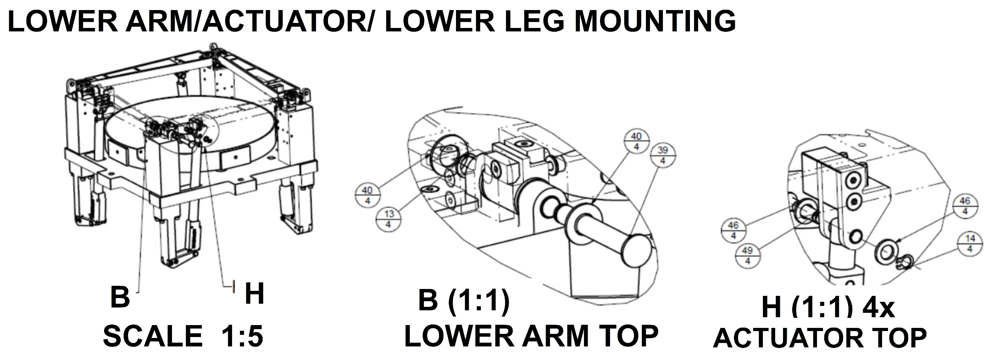
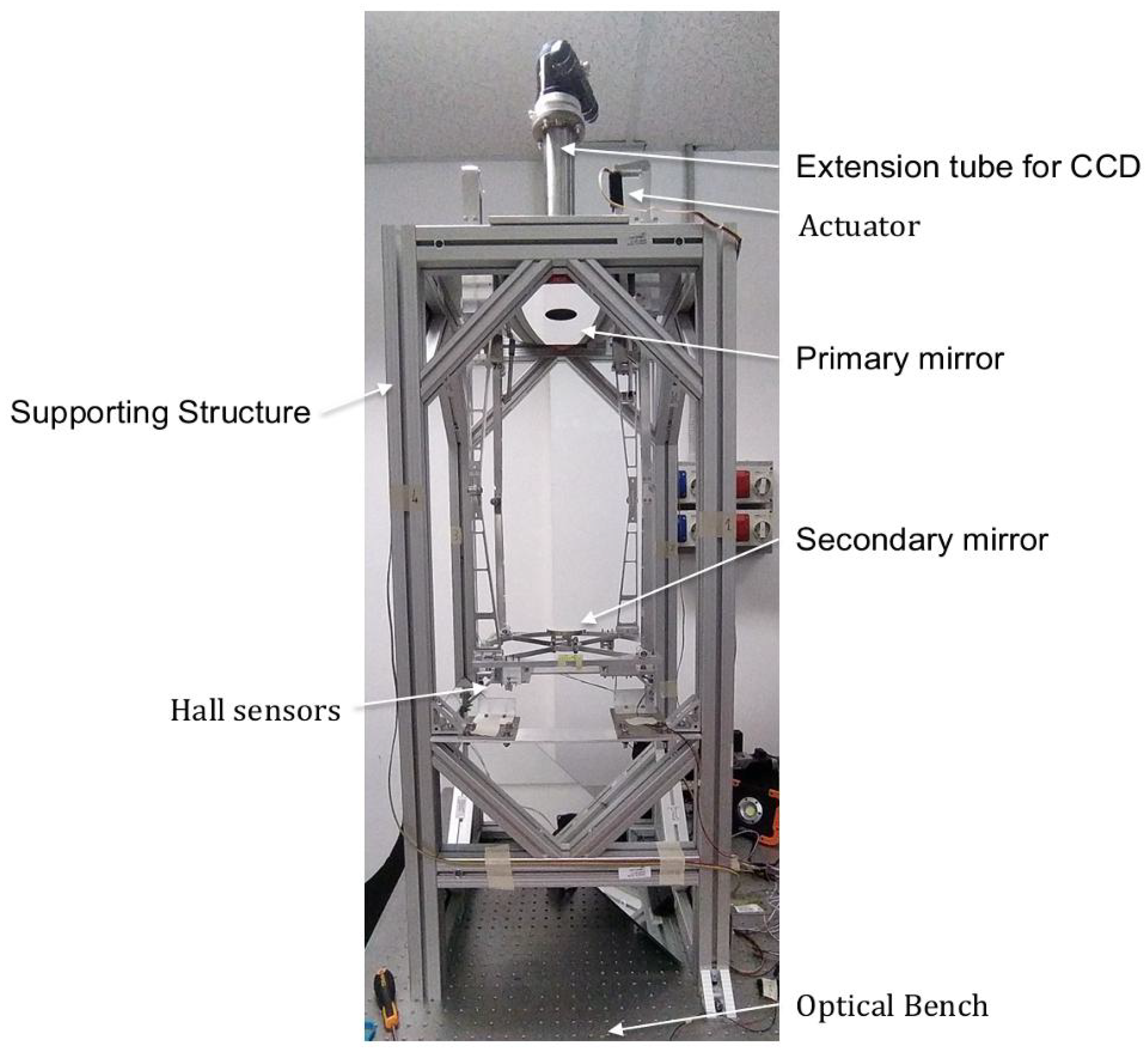
4.1. Telescope Structure

The telescope can be deemed as comprising the following subsets, as shown in Figure 3:
-
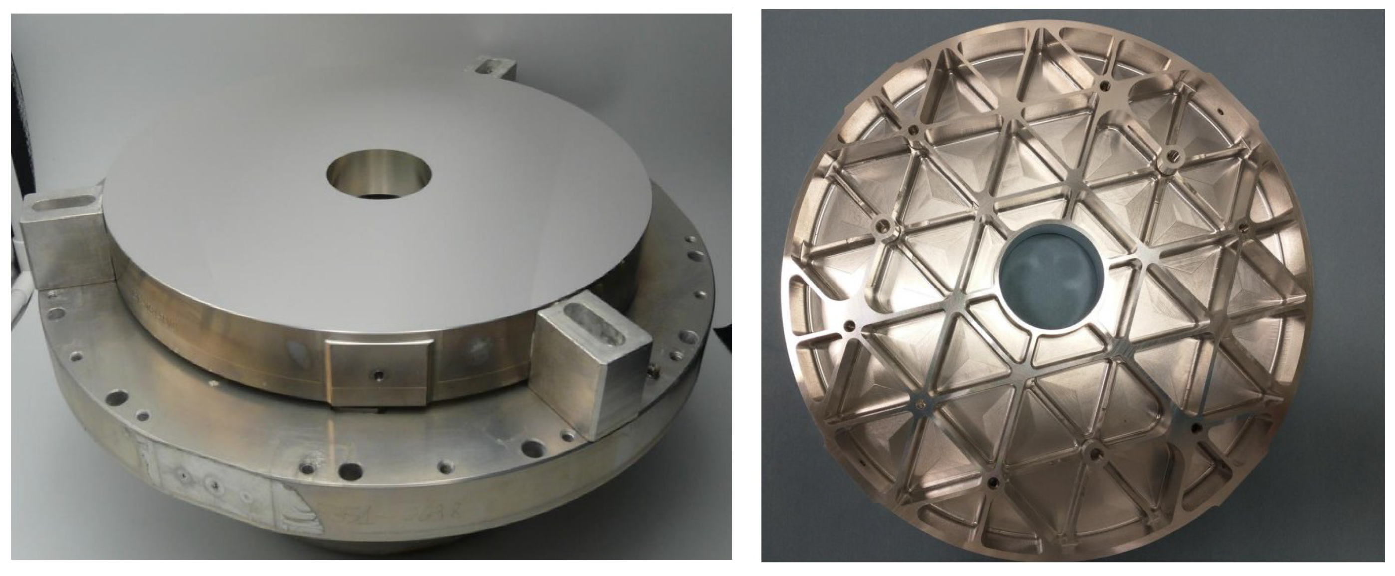
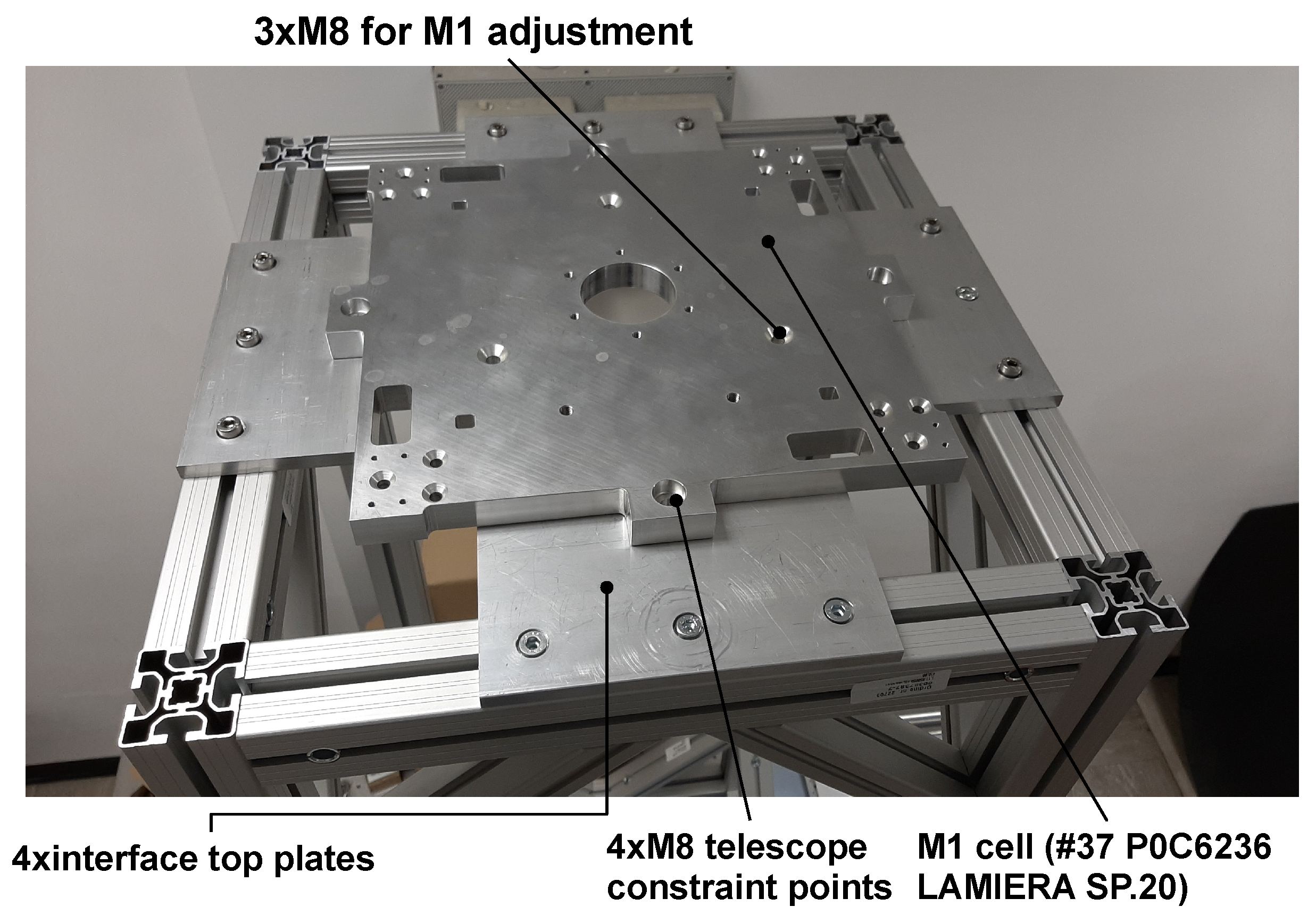
a baseplate hosting the primary mirror and MIMA interface plate; four opening pockets of 45 × 20 mm allow for the actuators passage.
-
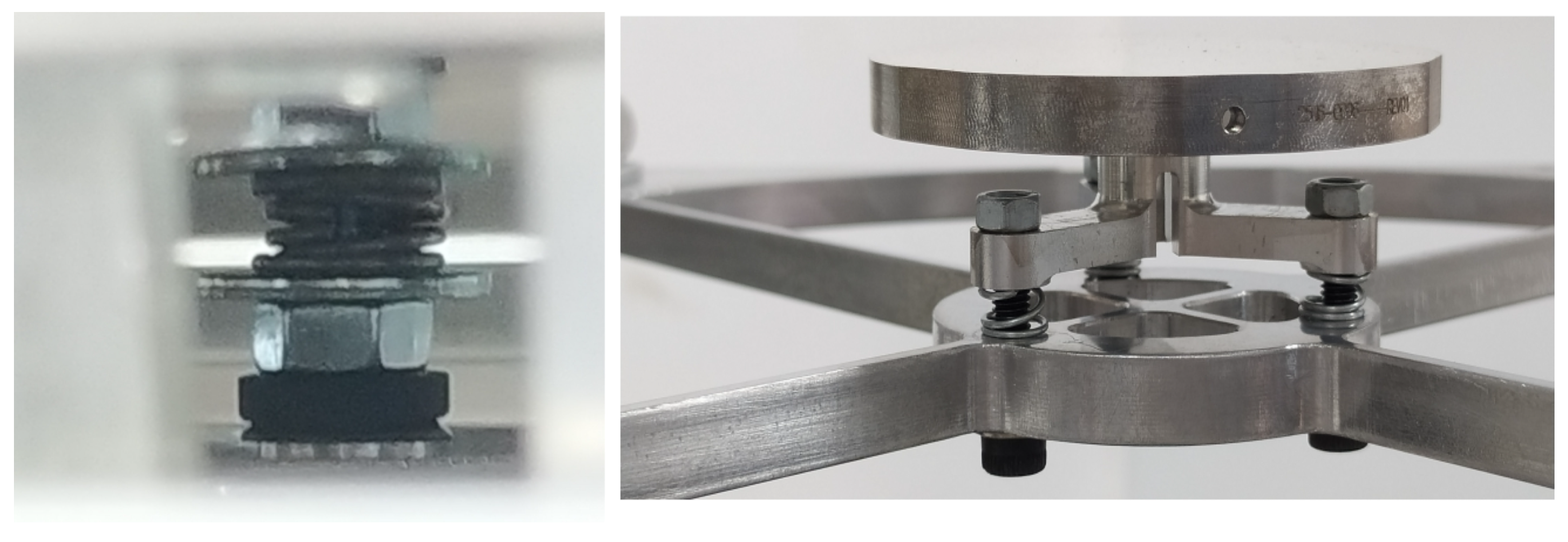
four supporting blocks respectively for the actuators and the articulated lower arms, containing the revolute joints to carry out the deployment motion.
-
four upper articulating arms with hinges connected to the top ring with the secondary mirror subunit.
In other terms, the mechanism comprises four dyads, each with three revolute joints, whose axes are mutually rotated counterclockwise by 90°. The material selected for the baseplate and the other mechanical components is EN AW-6061 T6.
The deployed configuration is achieved using linear actuators, one for each articulated arm, four in total. Furthermore, they are available in a wide range of versions depending on the power, load capacity, stroke, and speed. The selection of the specific linear actuator model has required analysis and testing of the range of forces and strokes needed to achieve the deployment [13].
The mass that the actuators have to move, which includes the articulation braces, HDRM inserts, support, and actuator inserts, and their pins, is about 2.2 kg. Considering an utmost safety factor of 5, namely a load capacity of 150 N for the highest peak force and a stroke length of ca. 100 mm, we chose a rod actuator model L16 by Actuonix, with a maximum gear reduction of 150:1, capable of reaching forces of 250 N and a stroke of 140 mm, far above and thus compliant with the DORA requirements. Each rod actuator can be equipped with a specific control board and can be commanded via PC using a proprietary software utility (Figure 4). However, to achieve a higher level of stroke accuracy with respect to the proprietary control board, we preferred another solution consisting of directly connecting the actuators to a Digilent motor adapter integrated with a MyRIO-1900 microcontroller by National Instrument (Figure 5).
There are actually two valid methods for synchronizing the four actuators: one is to send a common PWM (Pulse Width Modulation) signal through the LAC boards, which allows for the independent adjustment of each actuator; the other one is simply letting each actuator run at the selected speed without any closed loop. This approach is feasible, as the four actuators are symmetrically constrained, carefully calibrated, carry the same load, and are deployed well below their duty cycle limit. Moreover, as we will see later, the telescope is deployed in a configuration that minimizes the contribution of gravity, thus effectively redistributing the load among the actuators within an accuracy of 5%.

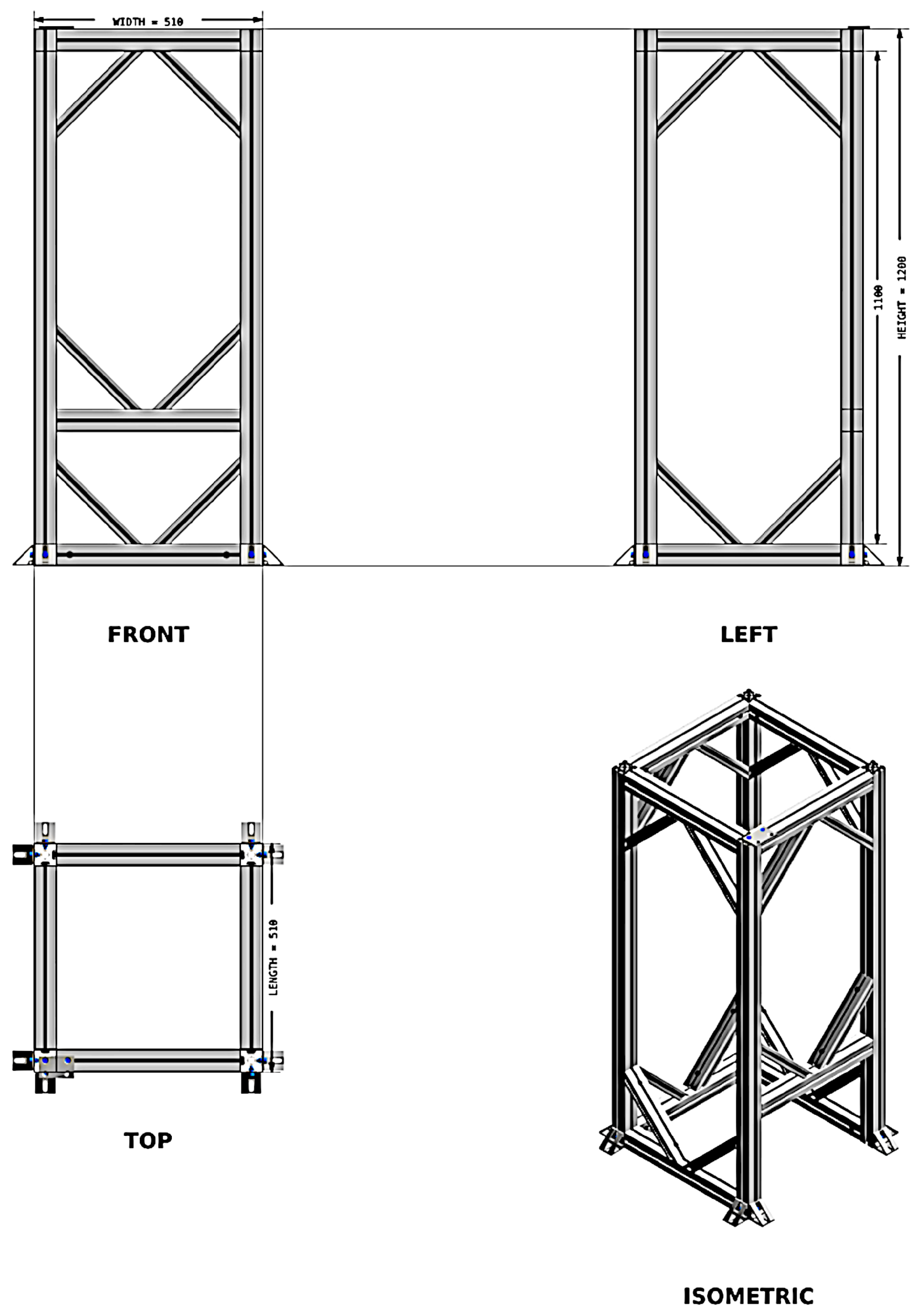
4.2. Supporting Frame Structure

The telescope is a fairly large instrument when deployed with an envelope of 350 mm × 350 mm × 800 mm. The first decision for the laboratory setup was on how to support the telescope on the optical bench and in which configuration to operate the deployment. Every solution has its own advantages and drawbacks: deploying it vertically in the usual way, where the actuators are pushing the top ring upwards, makes it easy to manage the focal plane instrument as it is close to the optical bench; deploying it horizontally would be the recommended installation for the alignment via the laser collimator but would result in a relatively large flexure deformation without a dedicated mechanical support, which could prevent us from verifying the accuracy of the mechanism positioning along the direction of gravity.
In fact, a first check on the telescope structure at a zenith distance of 90° provided as an outcome a sag error of 186.8 µm; since it exceeds the maximum allowed value of 100 µm, such option was discarded.
Deploying it vertically with the actuators pushing the secondary mirror downwards is the preferable option, since the actuators operate under the minimum effect of gravity. A modal analysis has also been conducted to check compliance with the frequency requirements: the first four eigenmodes are between 40 and 131 Hz. Therefore, we have decided to assemble the telescope in an upside-down fashion fixed to a supporting truss bolted onto the optical bench. Such an arrangement ensures that the additional focusing frame structure, bolted on the plate interfacing with the primary mirror cell, does not interfere with the ceiling. Moreover, it facilitates positioning the collimating laser system on the optical bench. The truss structure made of Al 6061, with outer dimensions of 510 × 510 × 1100 mm, consists of 12 square hollow tube bars of 50 × 50 mm, plus 16 oblique bars 30 × 50 with a stiffening function. Threaded inserts for M8 screws allow the connections among the bars.
A finite element model analysis (FEA) has been performed for the final version of the telescope structure in the upside-down layout to check if such a configuration is compliant with the allowed displacements. To constrain the FEA model, four cylindrical contacts have been inserted in the M8 holes, and a remote force of 200 N has been applied at the center of mass, located in the proximity of the M2 vertex. The magnitude of the total deformations ranges from a minimum value of 3.40 up to 11.5 μ m. The estimated Von Mises stress distribution value is about 37 MPa, giving a margin of safety larger than 5. The overall layout of the supporting truss is depicted in Figure 6. The supporting truss is anchored onto an optical bench via eight angular blocks measuring 48 × 48 mm through M6 threads. The selected optical bench is a STANDA, type 1HT10-15-20, with 1.5 × 1 m dimensions, a 20 cm thickness, and a flatness error of 0.1 mm/m2.

4.3. The Primary and Secondary Mirrors

Both mirrors are made of aluminum 6061-T651 and diamond-turned. The diamond turning process has been followed by the figuring and polishing processes to achieve the required surface quality. A protected silver coating process was carried out at approximately 80 °C, during which internal stresses were released, resulting in a slight modification of the mirror’s surface shape, namely a variation of curvature radius, which measures C 1 = 1560.34 mm. Such coating warrants a reflectivity higher than 95% within the spectral range of 550–4000 nm and better than 92% up to 10 μ m. The primary mirror is lightweight, with a mass of 1.8 kg, milled from the blank to reach a thickness of 4 mm and generating ribs with an average thickness of 2.5 mm and fillet radii of 12 mm (Figure 7). The cells and ribs design task preserves an adequate stiffness against the vibration or deformation of the mirror’s optical surface. Its position in tip-tilt and despacing can be adjusted when the mirror is mounted on the S/C interface baseplate (Figure 3), acting on three M8 × 50 screws with coil springs together with three coupled tapered washers, distributed at 120° from the center and at a radial distance of 99 mm.
An actual surface error of 416.5 nm rms, very close to the best-effort specification of 400 nm RMS has been achieved. It slightly increased after coating and due to the mirror fixation during the machining process, but it is still compatible with MIMA specifications. The surface form errors for both mirrors, measured via a non-contact profilometer MPR700, have been input into Zemax to estimate the actual residual aberrations due to the manufacturing process. For a closer description of the surface map errors for the primary mirror and their statistical distribution with respect to the radius, we refer to [14].

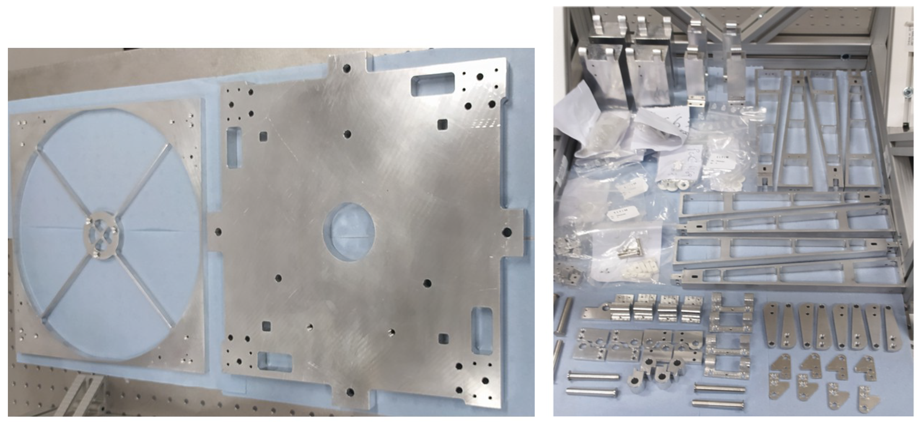
5. Assembling Procedure

Mechanical Assembling
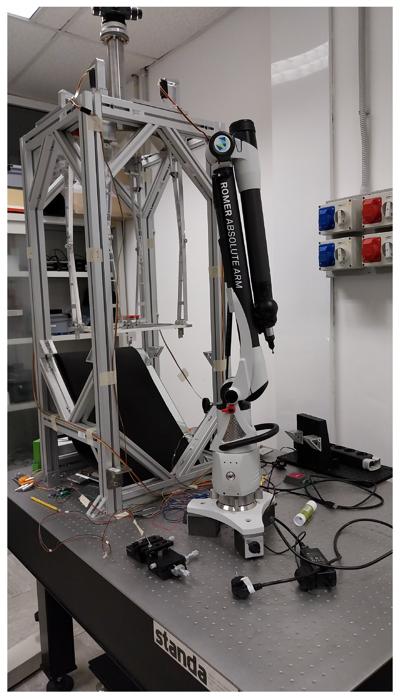
The first thing we did during the assembling procedure was place M1 on the optical bench and fasten it to the primary cell via three M5 × 50 mm screws, along which we inserted three coil springs together with three corresponding coupled tapered washers. As a second step, we bolted the primary cell plate, with an outer envelope of 320 × 320 × 20 mm (see Figure 8), with M1 preliminarily mounted, onto the supporting frame structure via four interfacing plates and M8 screws. We then fastened the M2 secondary mirror to the top ring via three M3 × 40 mm screws, along which we inserted three coil springs together with three corresponding coupled tapered washers (Figure 9).
Next, we proceeded to mount the supporting blocks, which hold the lower arms and the actuators. Additionally, we installed bushings, where the pins are inserted, along with washers for each hinge. Figure 10 illustrates the details of the joints for the lower arm connections. For each pin and hole pair, a manufacturing tolerance of H7/h7 was assigned, which corresponds to a clearance value of 30 μ m. The actuators must be installed in their fully retracted configuration. Subsequently, the upper arms and hinges of the top ring were assembled in a manner similar to that used for the lower arms.
The actuators must be mounted in the fully retracted configuration. The upper arms and hinges of the top ring were subsequently assembled similarly (as shown) for the lower arms.
Then the extension tube providing the back focal length was mounted on top of the primary cell through an attachment flange with an external diameter of 96 mm via 6× M6 screws. The focuser, manufactured by Tecnosky Titanium, is screwed onto the other end on a flange with a threaded termination. The main components before and after the assembling setup are illustrated in Figure 11 and Figure 12.

6. Test Procedure

In order to measure the accuracy and repeatability of the telescope deployment, and to ensure that the retrieved values are compliant with the tolerance analysis assumed by the optical design, a Hexagon absolute Romer arm was used. This measuring device is a seven-axis articulated arm with interchangeable scanning probes (see Figure 13). For our specific application, we used a ∅ 6 mm spherical tactile probe of Rubidium, with an estimated intrinsic measuring precision of 30 μ m. Since our main objective is to analyze the statistics of the repeatability during deployment, it is more suitable to always refer to the same points on the structure. After fixing the Romer onto the optical bench, the absolute position in space of the arm tip was calibrated, defining a global reference system. At this stage, we are able, by defining a local coordinate system fixed to the telescope, to measure any absolute position in space and derive displacements of the same points from a previous measurement.

6.1. Measurements Methodology

The allowed tolerances from the optical design are those derived from the sensitivity analysis of the optical design, respectively: Δ x, Δ y, Δ z = ±100 μ m for decentering and despacing and Δ α , Δ β , Δ γ = ±0.01° for tip-tilt, as described before. For convenience, we chose the three holes, each of ∅ 3 mm diameter for pin insertion, located on the top-ring and indicated by P1, P2, and P3 in Figure 14, as measurement points. In the local reference, the X-axis is oriented along P1–P2, the Y-axis along P2–P3, and the Z-axis vertically pointing upwards. The three points lie on a circle, with its center ideally lying on the optical axis, intersecting the vertex of the secondary mirror. We aim to analyze the statistics of the displacements of the circle center, the radius, and the top-ring rotation angles. Since we are assuming that the top ring plate behaves like a rigid body, we are interested in determining its displacements and rotations. Out of several deployment test sequences performed, after discarding the ones employed to set up the proper reference system, we identified nine deployment cycles. From Figure 14, we see that the holes are located at the vertices of a square with a side length of 243.15 mm, while the radius of the circle intersecting the three pins is equivalent to r = 171.935 mm.

6.2. Outcomes from Data Analysis

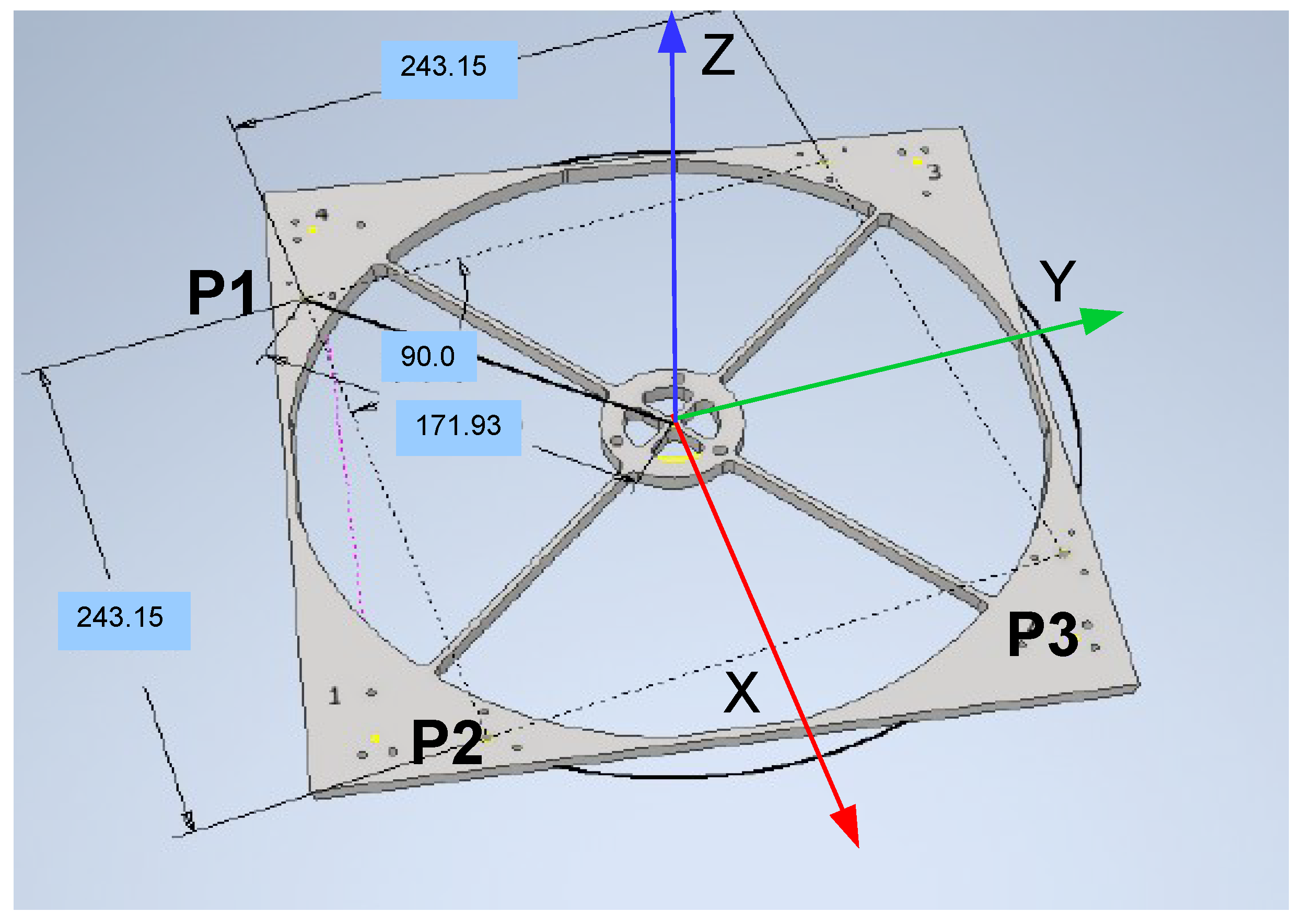
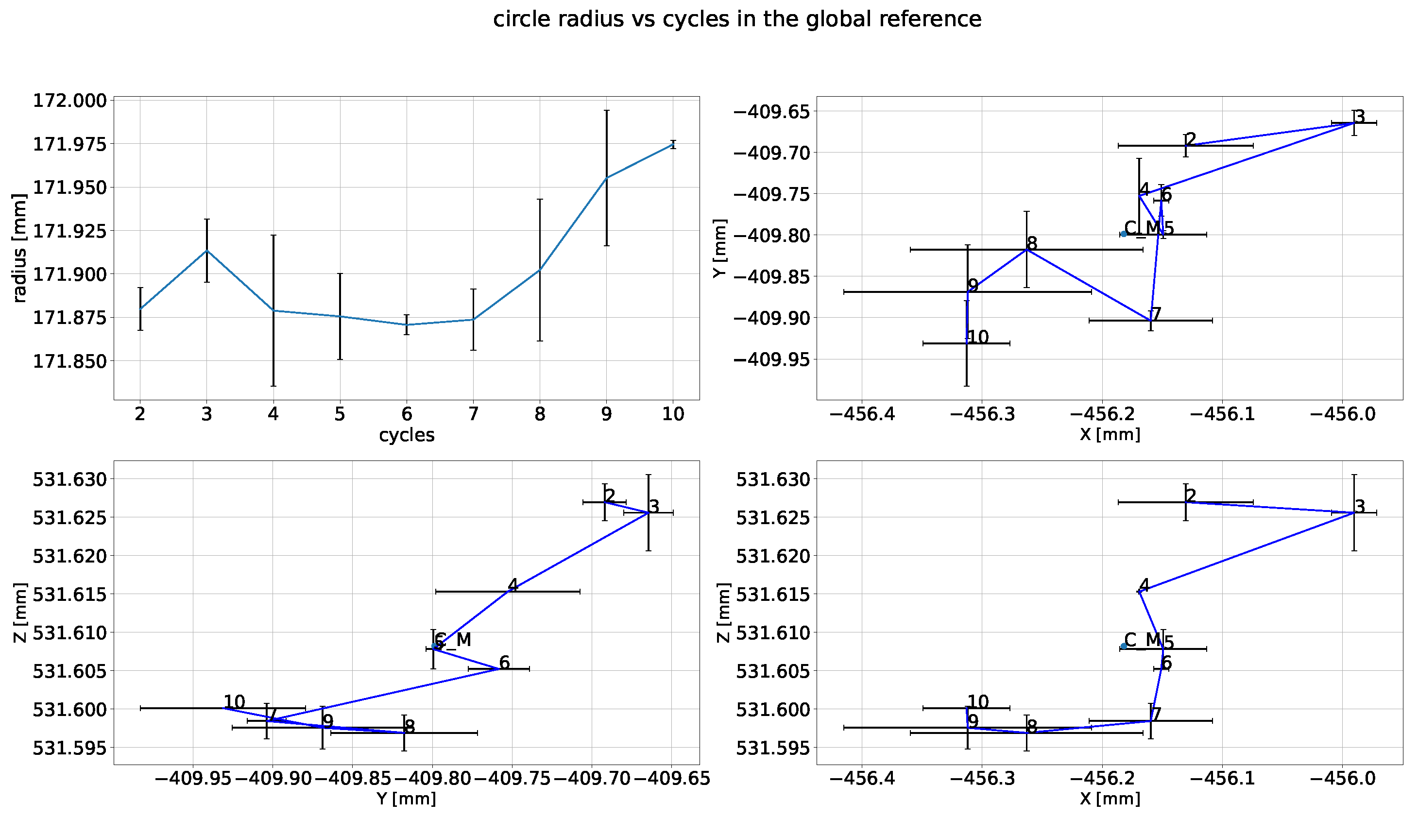
6.2.1. Analyzing the Pin Positions

For each cycle, we performed three measurements of the absolute positions of the three holes to minimize operator errors. Then, we computed the average value of the three measurements for each cycle. The differences between these average values give us the sequential displacements and their standard deviations of the repositioning errors.
Measures with null or very close to zero standard deviation imply that they are lower than or equal to the probe maximum resolution of 30 μ m and are not correlated with the same cycle. Specifically, when calculating the standard deviations within each cycle for pin 1 in the three directions, they are consistently lower than those for the other two pins, reaching its maximum value of max( σ P 1 x ) = ±85 μ m in cycle 5, while in cycle 8 max( σ P 1 z ) = ±8.1 μ m. Pin 2 records its maximum standard deviation of max( σ P 2 y ) = ±157.9 μ m in cycle 8. Moreover, we have compared the precision in the measurements, considering that the relative distances between the pins must remain unchanged, as they belong to a rigid body. The actual distances determined from the CAD are equivalent to 243.152 mm for P1–P2, P2–P3 and 343.87 mm for P1–P3. However, there’s a noticeable drift from the actual value in cycles 3 and 6, attributable to the structure’s sensitivity to motion on the X-Y shear plane during the measuring process (Figure 15).
The other important parameters to check, in order to observe how the center of mass of the secondary mirror moves, are the coordinates of the center of the circle fitting through the 3 pins. Specifically, the average value of the displacements in the three coordinates provides us with a first indication of the motion repeatability. As we can observe in Figure 15, the largest values ( Δ x = 103.25 μ m, Δ y = 56.7 μ m) are reached in the ninth cycle; in the Z direction, we observe more modest displacements: Δ z = 4.96 μ m in the third one. From the measured coordinates of the three pins P1,P2,P3, it is also possible to calculate the orientation of the plane intersecting them by taking the cross product of the two vectors connecting them A B = P 2 P 1 ; B C = P 3 P 2 ; N ^ = A B B C . Nevertheless, the direction cosines of the normal to such a plane do not exactly correspond to the Euler angles due to the rototranslational effect of the top ring plate (assumed as a rigid body). The estimated value for the center of the circles in global coordinates is equivalent to CM = [−456.182, −409.798, 531.608] mm.

6.2.2. Displacements and Euler Angles Calculation

Within the assumption of small linear and angular displacements and that the top ring plate is behaving as a rigid body with six degrees of freedom, it is possible to determine its center of mass displacement and the Euler angles starting with the following relationship:
x O P y O P z O P = x O O y O O z O O + [ R ] x O P y O P z O P
with R being a rotation matrix and therefore orthogonal ( R 1 = R T ); O P represents the position of any pin in the global reference frame, O O are the coordinates of the center of the circle in the global reference frame, and O P are the vector points in local coordinates. R has the following form, valid for small angular displacements:
R = 1 Δ θ z Δ θ y Δ θ z 1 Δ θ x Δ θ y Δ θ x 1
Equation (3) can be also rearranged in another way to express it as a function of the angular displacements Δ θ x ,   Δ θ y ,   Δ θ z [15,16]:
δ x P 1 δ y P 1 δ z P 1 δ x P 2 δ y P 2 δ z P 2 δ x P 3 δ y P 3 δ z P 3 = 1 0 0 0 Z O P 1 Y O P 1 0 1 0 Z O P 1 0 X O P 1 0 0 1 Y O P 1 X O P 1 0 1 0 0 0 Z O P 2 Y O P 2 0 1 0 Z O P 2 0 X O P 2 0 0 1 Y O P 2 X O P 2 0 1 0 0 0 Z O P 3 Y O P 3 0 1 0 Z O P 3 0 X O P 3 0 0 1 Y O P 3 X O P 3 0 Δ x Δ y Δ z Δ θ x Δ θ y Δ θ z
This method is generally applied to deformations that act on a rigid body, such as nodal displacements of an optical surface, which typically involve many data points. Its purpose is to determine the despacing, decentering, and tip-tilts of its center of mass. Likewise, we construct the displacement vector in the first member of the equation above, which, for each cycle, is equivalent to the difference between the average values of the pin coordinates of that cycle and the mean-mean values of the pin coordinates for all cycles: δ r P i ( j ) = < r P i ( j ) > < r P i > ¯ expressed for a single pin. By premultiplying the displacement vector by the pseudoinverse of the rotation matrix, we receive the displacements and Euler angles of the top ring frame. Table 2 contains the estimated values of the top ring motion after each deployment, i.e., between the cycles: Δ x, Δ y, and Δ z represent decentering and despacing, Δ α ,   Δ β tip-tilt and Δ γ twist, or pitch, roll and yaw.
It is clear that the torsion effect prevails over the others, but the standard deviation remains below ±0.01°, therefore matching the requirements from the tolerance analysis. As meaningful parameters, we have enlisted the average of the absolute values for the displacements, their standard deviation, and peak-to-valley measurements. Such displacements, along with their relative standard deviations, are plotted in Figure 16. The deployment causes a shift of the line of sight by less than 100 µm along the three axes. In particular, the defocusing effect is limited to Δ z = 11   μ m.
Taking the standard deviation of the displacements as an indicator of the positioning error of the telescope, we confirmed that all values are compliant with the original requirements.

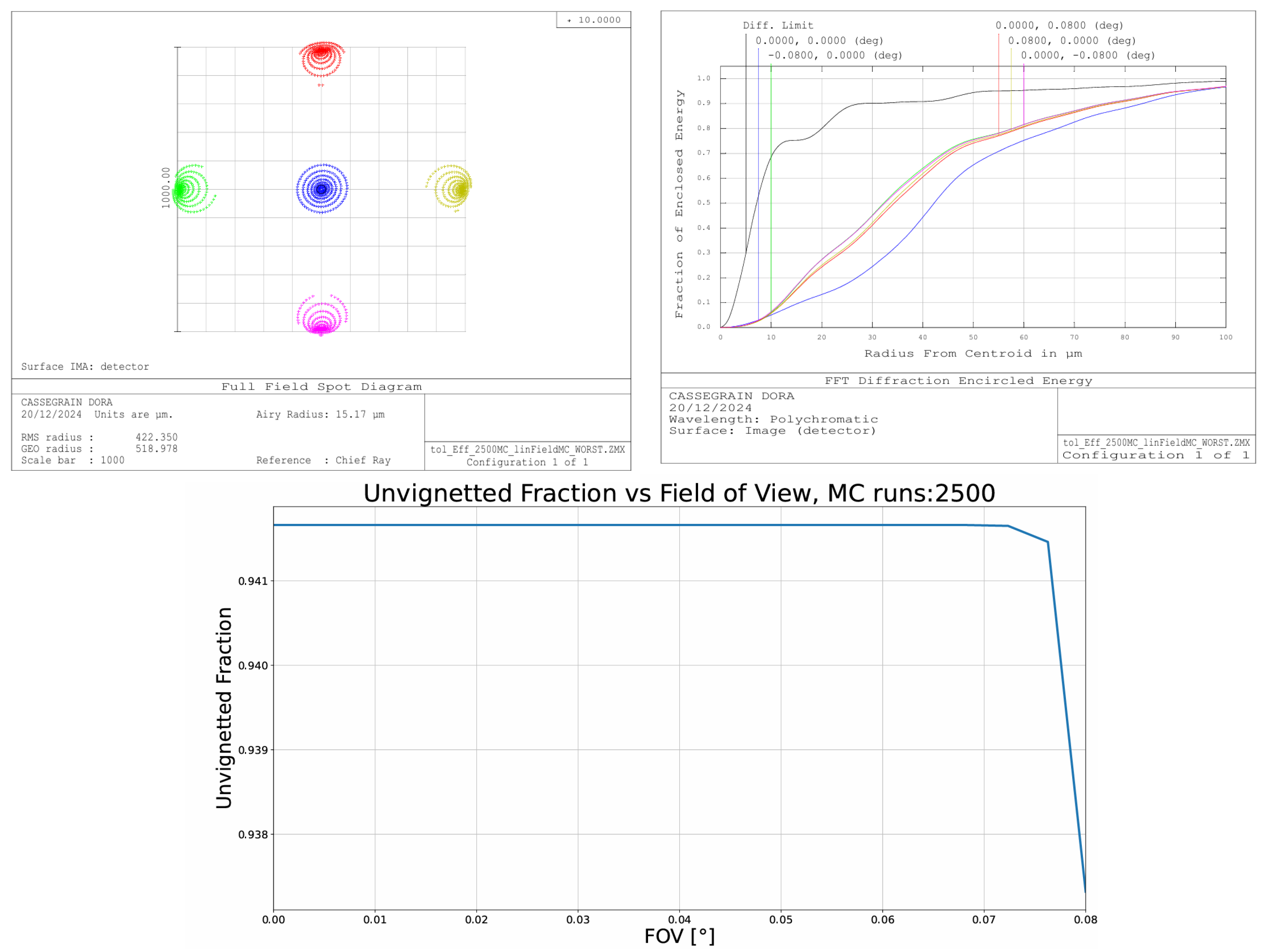
6.3. Updating the Tolerance Analysis

As a subsequent step, we fed the standard deviations of the resulting displacements in Table 2 back into a new tolerance analysis in Zemax in order to estimate the resulting aberrations contributing to the overall optical error budget. We have also applied the operand TIRR for surface irregularity of ± λ / 4 to the primary mirror, for a reference wavelength of λ = 10 μ m, which is the nominal wavelength range for the MIMA instrument.
As a valid criterion, the root mean squared spot radius was chosen, with no compensator assigned by default over the back focal distance, to optimize for image degradation: this way, the expected values are not corrected for the actual misalignment. The Table 3 contains the tolerance operands with the lowest and largest input operand values and the outcomes from RMS the spot radius relative to the worst case. As we can deduce from Figure 17, there is a slight worsening of 6.9 μ m in the spot radius with respect to the ideal conditions and an utmost OPD of 0.6 λ .

7. Conclusions

We have successfully accomplished the AIT phase of the DORA (deployable optics for remote sensing applications) project. The main task was to measure the repeatability of the performance of a telescope deployment mechanism in order to ensure that the tilts, decentering, and despacing values are compliant with the requirements derived from the sensitivity analysis. In conclusion, we have demonstrated that the present design of the mechanism used to deploy a Cassegrain telescope made of a monolithic primary mirror and a secondary mirror mounted on extendable arms satisfies the requirements for the MIMA point spectrometer working in the infrared range.
However, we have to point out that such a mechanism is particularly interesting also for applications where a 2D detector is used (imaging spectrometers, cameras, etc.). A design for these new instruments has more stringent requirements than those posed by a point spectrometer, and we have identified a few possibilities to further improve the opto-mechanical performances, which can be summarized in the following:
  • Reducing backlash in each of the supporting blocks for the lower arms or replacing them with four whole blocks (which now, instead, consist of 3 components).
  • Introducing a smart hexapod structure behind M2: it can be either a miniaturized platform like the one provided by Physik Instrumente (PI) with six degrees of freedom capability or the one offered by Smaract company, the Smarpod model, which is equivalent to a hexapod but with 3 multi-linear stages at 120°. This item, which has been investigated for its limited envelope, has a baseplate diameter of ∅ 70 mm interfacing with the fixed top ring assembly and a ∅ 45 mm flange diameter interfacing with M2. It would represent the best tradeoff solution, as it is a fully controlled 5 dof platform with a minimum number of interface parts to manufacture, rather compact, which can be quickly plugged in and calibrated, and incorporates optical and inductive sensors. In particular, the Smarpod 70.42 type, weighing about 200 g, would be suitable [17].
  • An alternative solution with respect to the Hexapod involves two different types of piezoactuators currently adopted in various astronomical instruments: two multistacked PI-601.3SL for correction along the X and Y directions and three APA-120S from Cedrat Technologies for providing Z motion and tilts around X and Y. The shell shaped APA type of piezoactuators, providing three degrees of freedom compensation (Z, θ x , θ y ), has been deployed to steer M5 for ELT [18]. They all incorporate sensors for closed-loop control and have to come precalibrated for the specific application and need, including strain gages, an amplifier, and controller boards.
  • For both solutions, an additional mechanical interface is needed, consequently increasing the distance between the top ring plate and the primary mirror cell.

Author Contributions

Conceptualization, I.D.V., F.C. and G.F.; methodology, I.D.V. and F.C.; software, I.D.V., G.R. and D.B.; validation, I.D.V., D.B. and A.M.; formal analysis, I.D.V., F.C. and B.S.; investigation, F.C., G.B. and G.F.; resources, I.D.V., G.R., D.B. and A.M.; data curation, I.D.V. and F.C.; writing—original draft preparation, I.D.V.; writing—review and editing, I.D.V. and F.C.; supervision, F.C. and G.F.; project administration, F.C., G.F. and G.B.; funding acquisition, F.C., G.F. and G.B. All authors have read and agreed to the published version of the manuscript.

Funding

This research was funded by MIUR–PON “Research and Innovation”/PNR 2015–2020, project no. ARS01_00653, belonging to the specialization “aerospace” area.

Data Availability Statement

The data presented in this study are available on request from the corresponding author.

Acknowledgments

We would like to thank our colleague Fabio Muleri from IAPS for his significant contribution to the Romer arm calibration and measurements procedure during the deployment tests. The authors also thank the Editor and anonymous Reviewers for critical discussion and supportive suggestions.

Conflicts of Interest

The authors declare no conflicts of interest.

References

  1. Muslimov, E.R.; Sakhabutdinov, A.Z.; Morozov, O.G.; Pavlycheva, N.K.; Akhmetov, D.M.; Kharitonov, D.Y. Digital Holographic Positioning Sensor for a Small Deployable Space Telescope. Appl. Sci. 2022, 12, 4427. [Google Scholar] [CrossRef]
  2. Xue, Y.; Li, Y.; Guang, J.; Zhang, X.; Guo, J. Small satellite remote sensing and applications—History, current and future. Int. J. Remote. Sens. 2008, 29, 4339–4372. [Google Scholar] [CrossRef]
  3. Bellucci, G.; Saggin, B.; Fonti, S.; Biondi, D.; Cerulli, P.; Luca, M.; Altieri, F.; Mattana, A.; Alberti, A.; Marzo, G.; et al. MIMA, a miniaturized Fourier infrared spectrometer for Mars ground exploration: Part I. Concept and expected performance. In Sensors, Systems, and Next-Generation Satellites XI, Florence, Italy, 17–20 September 2007; SPIE: Bellingham, WA, USA, 2007. [Google Scholar] [CrossRef]
  4. Saggin, B.; Alberti, E.; Comolli, L.; Tarabini, M.; Bellucci, G.; Fonti, S. MIMA, a miniaturized infrared spectrometer for Mars ground exploration: Part III. Thermomechanical design. In Proceedings of the Sensors, Systems, and Next-Generation Satellites XI, Florence, Italy, 17–20 September 2007; Habib, S., Meynart, R., Neeck, S.P., Shimoda, H., Eds.; International Society for Optics and Photonics, SPIE: Bellingham, WA, USA, 2007; Volume 6744, p. 67441S. [Google Scholar] [CrossRef]
  5. Fonti, S.; Marzo, G.A.; Politi, R.; Bellucci, G.; Saggin, B. MIMA, a miniaturized Fourier spectrometer for Mars ground exploration: Part II. Optical design. In Proceedings of the Sensors, Systems, and Next-Generation Satellites XI, Florence, Italy, 17–20 September 2007; Habib, S., Meynart, R., Neeck, S.P., Shimoda, H., Eds.; International Society for Optics and Photonics, SPIE: Bellingham, WA, USA, 2007; Volume 6744, p. 67441R. [Google Scholar] [CrossRef]
  6. Martellato, E.; Piccirillo, A.M.; Ferraioli, G.; Rotundi, A.; Della Corte, V.; Palumbo, P.; Alcaras, E.; Appolloni, L.; Aulicino, G.; Bertini, I.; et al. A New Orbiting Deployable System for Small Satellite Observations for Ecology and Earth Observation. Remote Sens. 2022, 14, 2066. [Google Scholar] [CrossRef]
  7. Capaccioni, F.; Bellucci, G.; Rinaldi, G.; Saggin, B.; Valnegri, P.; Filacchione, G.; Della Corte, V.; Magrin, D.; Angarano, M.; Filippetto, D.; et al. DORA: Deployable Optics for Remote sensing Applications. In Proceedings of the European Planetary Science Congress, Online, 21 September–9 October 2020; Volume 14. EPSC2020-1003. [Google Scholar] [CrossRef]
  8. Villalba, V.; Kuiper, H.; Gill, E. Review on thermal and mechanical challenges in the development of deployable space optics. J. Astron. Telesc. Instruments Syst. 2020, 6, 010902. [Google Scholar] [CrossRef]
  9. Valnegri, P.; Saggin, B.; Scaccabarozzi, D.; Corti, M.; Capaccioni, F.; Bellucci, G.; Rinaldi, G. Comparison of candidate mechanism concepts for a deployable space telescope. In Proceedings of the 2021 IEEE 8th International Workshop on Metrology for AeroSpace (MetroAeroSpace), Naples, Italy, 23–25 June 2021; pp. 92–96. [Google Scholar] [CrossRef]
  10. Rinaldi, G.; Capaccioni, F.; Bellucci, G.; Filacchione, G.; Di Varano, I.; Magrin, D.; Saggin, B.; Valnegri, P.; Della Corte, V.; Piccirillo, A.M.; et al. Deployable Telescope for Remote Sensing Applications. Opt. Express, 2025; in preparation. [Google Scholar]
  11. Ansys Zemax. OpticStudio User Manual. Ansys Inc. 2023. Available online: https://www.ansys.com/products/optics/ansys-zemax-opticstudio (accessed on 31 October 2024).
  12. Francis, W.; Lake, M.; Peterson, L.; Hinkle, J. Development of an Elastic Memory Composite Self-Locking Linear Actuator for Deployable Optics. In Proceedings of the 45th AIAA/ASME/ASCE/AHS/ASC Structures, Structural Dynamics & Materials Conference, Palm Springs, CA, USA, 19–22 April 2004. [Google Scholar] [CrossRef]
  13. Valnegri, P.; Saggin, B.; Scaccabarozzi, D.; Arrigoni, S.; Capaccioni, F.; Bellucci, G.; Rinaldi, G. DORA telescope project: Preliminary characterization of the deployment mechanism. In Proceedings of the 2022 IEEE 9th International Workshop on Metrology for AeroSpace (MetroAeroSpace), Pisa, Italy, 27–29 June 2022; pp. 550–555. [Google Scholar] [CrossRef]
  14. Di Varano, I.; Capaccioni, F.; Filacchione, G.; Rinaldi, G.; Bellucci, G.; Morbidini, A.; Saggin, B. Investigation of optical error budget for the DORA telescope. In Proceedings of the 2023 IEEE 10th International Workshop on Metrology for AeroSpace (MetroAeroSpace), Milan, Italy, 19–21 June 2023; pp. 84–88. [Google Scholar] [CrossRef]
  15. Andersen, T.; Enmark, A. Integrated Modeling of Telescopes; Springer Science & Business Media: Berlin/Heidelberg, Germany, 2011; Volume 377. [Google Scholar] [CrossRef]
  16. Di Varano, I.; Yuan, S.; Woche, M.; Strassmeier, K.G.; Weber, M. ELT-HIRES the high-resolution spectrograph for the ELT: Simulation results of polarimetric aberrations for the polarimetric module. In Proceedings of the Modeling Aspects in Optical Metrology VII, Munich, Germany, 24–27 June 2019; Society of Photo-Optical Instrumentation Engineers (SPIE) Conference, Series. Bodermann, B., Frenner, K., Silver, R.M., Eds.; SPIE: Bellingham, WA, USA, 2019; Volume 11057, p. 1105715. [Google Scholar] [CrossRef]
  17. Technical Datasheet: Smarpod-70-42.pdf. SmarAct GmbH. 2024. Available online: https://www.smaract.com/en/smarpod/product/smarpod-70-42 (accessed on 15 June 2024).
  18. Company Weblink. 2024. Available online: https://cedrat-technologies.com/wp-content/uploads/downloads/piezo_actuators_for_astronomical_instrumentation.pdf (accessed on 31 October 2024).
Figure 1. (Top panel): telescope optical layout including MIMA with the main dimensions: entrance pupil, mirrors separation, and back focal length. (Bottom panel): Spot diagrams relative to the ideal case for a wavelength of 10 μ m.
Aerospace 12 00224 g001
Figure 2. (Left panel): full field spot diagrams for the tolerance analysis worst case; the estimated Airy disk radius is 15.04 μ m for a 10 μ m wavelength. (Right panel): encircled energy fraction at different field angles compared to the diffraction limited mode. (Bottom panel): unvignetted fraction of rays over the entire FoV outcoming from 2500 Monte Carlo simulations for different combinations of linear and angular displacements.
Aerospace 12 00224 g002
Figure 3. Layout of the telescope, with the main subunits in the stowed and deployed configuration.
Aerospace 12 00224 g003
Figure 4. Top panel: Actuonix L16 model with relative stand-alone LAC board. Bottom panel: load capacity specs for different gear ratios. The red curve relative to a gear ratio of 150:1 corresponds to the selected actuator.
Aerospace 12 00224 g004
Figure 5. MyRIO board with Digilent motor adapter connected to it.
Aerospace 12 00224 g005
Figure 6. Layout views of the supporting structure for DORA laboratory setup.
Aerospace 12 00224 g006
Figure 7. Primary mirror layout after coating process and back view showcasing the cells and ribs pattern.
Aerospace 12 00224 g007
Figure 8. Details of the connection between the telescope M1 cell and the supporting frame through the specific interfacing plates.
Aerospace 12 00224 g008
Figure 9. (Left): details of the spring inserted between primary mirror with coupled washers and its holding cell. (Right): Details of the spring inserted between M2 and its supporting structure (the top ring).
Aerospace 12 00224 g009
Figure 10. Exploded views of the lower arm hinge on the block side and revolute joint connecting the actuator with the arm.
Aerospace 12 00224 g010
Figure 11. View of the full set of components, including the primary mirror baseplate and the top ring arranged on the optical bench before installation.
Aerospace 12 00224 g011
Figure 12. A snapshot of the telescope after a complete assembly on the supporting structure, including the optical bench, the Hall sensors, and the extension tube used to adapt a CCD in replacement of the MIMA instrument.
Aerospace 12 00224 g012
Figure 13. Romer Hexagon absolute arm in action in the lab.
Aerospace 12 00224 g013
Figure 14. Main distances and locations of the pins selected for the measurements, retrieved from Autodesk Inventor.
Aerospace 12 00224 g014
Figure 15. (Top left panel): mean values of the radii of the fitting circles for each of the nine (from 2 to 10) deploying cycles with their relative standard deviation. (Top right and bottom left-right panels): mean values of the offsets of the fitting circle center and their relative standard deviations, respectively, on X-Y, Y-Z, and X-Z planes. The average value of the calculated centers, named CM, is also indicated.
Aerospace 12 00224 g015
Figure 16. Plots of displacements and Euler angles of the local reference frame as pitch, roll, and yaw. The standard deviations are referred to the whole dataset from the second to the tenth cycle and are represented by a single value to avoid redundancy.
Aerospace 12 00224 g016
Figure 17. (Upper left panel): full field spot diagrams for the worst case of a Montecarlo tolerance analysis when applying the standard deviations of the displacements due to the deployment error. (Upper right panel): fraction of encircled energy at different field angles compared with the diffraction-limited value in black line. (Lower panel): fraction of unvignetted rays vs FoV for 2500 Monte Carlo runs, relative to the actual deployment errors.
Aerospace 12 00224 g017
Table 1. Telescope and spectrometer main optical requirements.
MIMA
Spectral range5–25 μ m
Spectral resolution5 cm−1 for atmospheric sounding
10 cm−1 for geologic mapping
Entrance pupil diameter26.4 mm
Focal length17.5 mm
Etendue (AΩ)0.01654 sr cm2
FOV3.2° ( 56 mrad)
Detector size1 mm2
DetectorPbSe
Telescope
f/#16.21
Optical efficiency0.6
Maximum entrance pupil300 mm
Central bore diameter60 mm
Exit pupil diameter79.142 mm
Effective focal length4863.287 mm
Back focal length1124.61 mm
Maximum radial field0.08°
Spatial resolution<6 km @700 km
FOV0.16°
Overall dimensions320 × 320 × 800 mm
Equivalent f/# telescope + MIMA1.25
Table 2. Euler parameters relative to each sequence of measurements, with their average, standard deviation, and pick to valley values. Pins standard deviations relative to each cycle are included, where null values refer to measurements smaller than the intrinsic Romer arm resolution.
Euler Displacementsst. dev. P1st. dev. P2st. dev. P3Average of the Absolute ValuesEuler Standard DeviationP-V
Δ x [mm]−2.7970 × 10 2 0.0100.0050.0255.15311480 × 10 2 5.85475931 × 10 2 1.74670486 × 10 1
−7.8780 × 10 2 0.0480.0550.035
2.1274 × 10 2 0.0100.0250.050
−1.3788 × 10 2 0.0850.0400.035
−3.2729 × 10 2 0.0850.0210.105
−7.8625 × 10 2 0.00820.0250.0249
6.7116 × 10 2 0.0290.0410.0679
4.7604 × 10 2 0.0050.0450.100
9.5890 × 10 2 0.050.0200.100
Δ y [mm]−9.9461 × 10 2 0.0200.0650.0156.49705303 × 10 2 7.36597189 × 10 2 2.27605805 × 10 1
−7.7048 × 10 2 0.0260.0300.024
−3.9517 × 10 2 0.0050.1000.025
5.8891 × 10 3 0.0250.0650.080
−7.6346 × 10 2 0.0150.0200.010
7.3216 × 10 2 0.0160.0730.033
3.3226 × 10 2 0.0490.1570.026
5.1883 × 10 2 0.0650.1150.045
1.2814 × 10 1 0.0500.0100.030
Δ z [mm]−1.870 × 10 2 0.0050.0050.09.5138551 × 10 3 1.10244034 × 10 2 3.00122214 × 10 2
−1.7073 × 10 2 0.00.01880.004
−7.0235 × 10 3 0.0050.0200.005
4.6162 × 10 4 0.00.0050.0
2.9650 × 10 3 0.00500.0
9.6382 × 10 3 0.00.0040.004
1.1304 × 10 2 0.0080.0040.094
1.0474 × 10 2 0.00.0050.005
7.9764 × 10 3 0.00500.005
Δ α [arcsec]−2.31319279 6.09268.661670753.00122214 × 10 2
1.90047357 × 10 1
−1.51306623 × 10 1
−2.35251697
6.11046078
−5.24722085
0.43148227
−2.40424968
1.83889158
Δ β [arcsec]7.71040722 9.498107881.31833530 × 10 1 4.35996864 × 10 1
3.43675620 × 10 1
−7.74680198
6.38635058 × 10 1
−3.65250933
−9.23212436
−6.44188792
−7.83445282
−7.85859018
Δ γ [arcsec]14.17840657 5.07874334 × 10 10 6.44609936 × 10 1 2.14035969 × 10 2
−7.07562743 × 10 1
7.85410568
5.81705298 × 10 1
6.15844734 × 10 1
8.03693703 × 10 1
6.30875773
−2.41983835 × 10 1
−1.33666599 × 10 2
Table 3. Tolerance analysis outcomes.
Minimum Maximum
Type ValueCriterionChangeValueCriterionChange
TTHI23−0.011024000.038293100.000598710.011024000.03709693−0.00059745
TEDX44−0.058500000.03769497 5.8310 × 10 7 0.058500000.03769497 5.8311 × 10 7
TEDX33−0.058500000.03768540 8.9891 × 10 6 0.058500000.03768540 8.9891 × 10 6
TEDY44−0.073600000.03769393 4.5696 × 10 7 0.073600000.03769651 2.1287 × 10 6
TEDY33−0.073600000.03733470−0.000359690.073600000.038026830.00033244
TETX33−0.002406000.03759846 9.5924 × 10 5 0.002406000.03778812 9.3736 × 10 5
TETZ33−0.017900000.03769439 2.0817 × 10 17 0.017900000.03769439 1.3184 × 10 16
TETY33−0.003661000.03769184 2.5497 × 10 6 0.003661000.03769184 2.5497 × 10 6
TIRR2 −0.250000000.044715110.007020720.250000000.03088357−0.00681082
Worst offenders:
Type ValueCriterionChange
TIRR2 −0.250000000.044715110.00702072
TTHI23−0.011024000.038293100.00059871
TEDY330.073600000.038026830.00033244
TETX330.002406000.03778812 9.3736 × 10 5
TEDY440.073600000.03769651 2.1287 × 10 6
TEDX440.058500000.03769497 5.8311 × 10 7
TEDX44−0.058500000.03769497 5.8310 × 10 7
TETZ33−0.017900000.03769439 2.0817 × 10 17
TETZ330.017900000.03769439 1.3184 × 10 16
TEDY44−0.073600000.03769393 4.5696 × 10 7
Estimated Performance Changes based upon Root-Sum-Square method:
Nominal RMS Spot Radius:0.03769439
Estimated change:0.00695166
Estimated RMS Spot Radius:0.04464605
Disclaimer/Publisher’s Note: The statements, opinions and data contained in all publications are solely those of the individual author(s) and contributor(s) and not of MDPI and/or the editor(s). MDPI and/or the editor(s) disclaim responsibility for any injury to people or property resulting from any ideas, methods, instructions or products referred to in the content.

