Article

Aerodynamic Characteristics and Dynamic Stability of Coning Motion of Spinning Finned Projectile in Supersonic Conditions

1
Xi’an Modern Control Technology Research Institute, Xi’an 710065, China
2
Beijing Institute of Astronautical Systems Engineering, Beijing 100076, China
3
School of Aerospace Engineering, Beijing Institute of Technology, Beijing 100081, China
*
Authors to whom correspondence should be addressed.
Aerospace 2025, 12(3), 225; https://doi.org/10.3390/aerospace12030225
Submission received: 23 January 2025 / Revised: 5 March 2025 / Accepted: 6 March 2025 / Published: 10 March 2025
(This article belongs to the Section Aeronautics)

Abstract

:
For a spinning projectile, coning motion induced by disturbances during flight can have a unique impact on the lateral force and yawing moment, which may further affect flight stability and maneuverability. The flow over a coupled spinning–coning projectile and a spinning projectile was numerically simulated by solving the unsteady Reynolds-averaged Navier–Stokes (URANS) equation with an implicit dual-time stepping method and a spinning–coning coupled motion model established through a dynamic mesh technique. The variation in transient and time-averaged aerodynamic characteristics with the angle of attack (AoA), dimensionless spin rate, and dimensionless cone rate was analyzed, and the specific effect of coning motion on the lateral force and yawing moment was revealed. Based on these findings, the yawing moment term in traditional angular motion theory was modified, and the flight response to the initial disturbance was discussed. The results indicate that the time-averaged lateral force and yawing moment of the spinning–coning coupled projectile are multiplied compared with those of the spinning projectile and vary linearly with the dimensionless spin rate and cone rate. The main factors affecting the lateral force are the coning motion-induced effective angle of sideslip (AoS), asymmetric expansion waves, and asymmetric vortices. The much larger yawing moment induced by spinning–coning coupled motion can more easily cause AoA divergence and flight instability.

1. Introduction

A low-cost guided projectile flies with a spin around its longitudinal axis to simplify the control system, achieving pitching/yawing control through a single channel, and eliminating ballistic dispersion caused by mass, thrust, and aerodynamic eccentric effects. However, when an axisymmetric spinning projectile flies at the AoA, the flow field is no longer symmetric about the AoA plane due to the coupling effect of the surface spin rate and crossflow rate; thus, an additional lateral force (out-of-plane force) and yawing moment (out-of-plane moment) are induced. This is referred to as the Magnus effect. Although the lateral force is only one-hundredth to on-tenth of the normal force, the yawing moment always causes the projectile to swing out of the AoA plane [1]. Furthermore, due to flight disturbances, the projectile’s longitudinal axis produces circular motion around the velocity vector, that is, the coning motion, which might lead to increased drag, shorter shooting range, larger dispersion, and flight failure [2,3]. It should be noted that the yawing moment of a spinning projectile is closely related to the characteristics of its coning motion. Related aerodynamic and stability problems have been the focus of researchers for decades.
In aerodynamic studies, the origin of the Magnus effect of a spinning projectile is complicated and involves many nonlinear flow phenomena, such as turbulent flow, shock/expansion waves, boundary layer separation, and the motion of unsteady vortices, which are quite sensitive to the Reynolds number, Mach number, AoA, spin rate, configuration, and so on [4]. With the rapid development of computer technology and numerical methods since the 21st century, extensive numerical studies have focused on the mechanism of the Magnus effect. The mechanism of the Magnus effect for spinning slender bodies can be described as asymmetric boundary layer transition, distortion, and separation [5,6]. For spinning finned projectiles, the impact of leeward asymmetric separation vortices on tails and the asymmetric resistance of the body on the tail root flow also contribute to the Magnus effect [7,8]. For more complex configuration with canards, the interference of canard-induced wash flow on the Magnus effect of the body and tail cannot be neglected [9,10]. The aerodynamic characteristics and the estimation method of a finned projectile experiencing spin–deformation coupled motion were also investigated [11].
Although computational fluid dynamics has been widely used in studies on aircraft aerodynamics [12,13,14], the possible aerodynamic coupling effect induced by spinning–coning coupled motion has not been considered. In 2014, Silton computed the static and dynamic aerodynamic characteristics of a 155 mm projectile. The static yawing moment was quite small, and the spin-induced yawing moment had certain limitations; therefore, the coning motion observed during the flight test could not be reproduced. Silton speculated that such a discrepancy might be originated from the spinning–coning coupling effect [15]. In 2018, Lu et al. simulated the flow field over a spinning–coning coupled Army–Navy Basic Finner Missile (ANF), combining the moving reference frame method and the one degree of freedom (1-DoF) forced motion method (δ = 25°). The results indicate that the shock/expansion waves around the fins produced a strong aerodynamic interference effect at Ma = 1.25 with high spin and cone rates, meaning that the nonlinear aerodynamic model is no longer appropriate [16]. In 2019, Pang et al. simulated the flow field over a spinning–coning coupled ANF by solving the URANS equations (δ = 10°). The ANF’s transient aerodynamic characteristics had a certain phase difference from the static results, and its amplitude was related to its spin rate [17]. However, the above studies neither compared the variation and origin of the lateral force or yawing moment of the spinning–coning coupled projectile with those of a spinning projectile nor conducted a flight stability analysis.
In a study on flight mechanics, Nicolaides and Murphy laid the theoretical foundation for the dynamic stability of spinning projectiles [18,19]. Han Zipeng proposed similar dynamic stability conditions [20]. The above theories can be used to quickly evaluate flight stability at a characteristic trajectory point. In 2004, Morote and Liaño calculated the aerodynamic characteristics of a 140 mm wraparound finned projectile using Euler equations, and clarified the reason for its flight failure by incorporating the stability theory [21]. In 2009, Murphy pointed out that an axisymmetric spinning projectile suffers periodic perturbations in its rolling and yawing moments at different rolling angles. The perturbation frequency is the same as the spin frequency, and spin–yaw lock-in might occur [22]. In 2013, Morote et al. described the conditions required for the occurrence of catastrophic yaw and proposed a method of avoiding it based on theoretical analysis and numerical simulation [23,24].
In general, during flight stability analysis of a spinning projectile, aerodynamic loads were always thoroughly modeled using linear or cubic nonlinear aerodynamic models, and the resulting stability conditions and suppression methods for coning motion were of great significance to the overall design. However, while the aerodynamic characteristics of the steady or spinning state were usually considered, the spinning–coning coupling effect was not considered, creating a gap between the simulation results and the actual situation. Since the lateral force and yawing moment are small, determining how to accurately predict their magnitude is an urgent matter for further development. Researchers have combined computational fluid dynamics (CFD) and rigid body dynamics (RBD) to simulate the flight process of uncontrolled and controlled projectiles; however, the coupled calculation is quite time consuming and is not suitable for preliminary engineering design [25,26].
In this study, the flow over the Air Force Modified Basic Finner Missile (AFF) with spinning–coning coupled motion and spinning motion was simulated by solving the URANS equations in combination with the dynamic mesh method. The aerodynamic characteristics corresponding to the two motion modes were also compared at different AoAs, spin rates, and cone rates. The effect of the coning motion on the lateral force and yawing moment was revealed. Finally, the expression of the yawing moment in angular motion theory was modified to accurately predict the dynamic response of a complex AoA, which was also compared with the result of a coupled CFD-RBD calculation for validation. Accurately predicting the aerodynamic characteristics of a projectile experiencing complicated motion is of great significance to ballistic design, control system design, and flight stability analysis.

2. Theoretical Basis

2.1. Governing Equations

In a Cartesian coordinate system, the integral form of the governing equations (N-S equations) of fluid flow based on grid motion can be expressed as follows [11]:
t Ω W d V + Ω F G · n d S = Ω H d V
where W represents the conservative variables, F and G are the inviscid and the viscid fluxes, respectively; and H is the source term (maintained at zero in this study). They can be expressed as follows:
W = ρ ρ u i e ,   F = ρ V V g r i d ρ u i V V g r i d + P I e V V g r i d + P V ,   G = 0 σ i j n i u j σ i j q i n i

2.2. Coupled Spinning–Coning Motion Mode

Figure 1 shows the definition of the coordinate systems, motion modes, and aerodynamic forces. Three coordinate systems: an inertial coordinate system, OXYZ; a quasi-body-fixed coordinate system, OXBYBZB; and a velocity coordinate system, OXVYVZV were used in this study, as shown in Figure 1a. The motion of the projectile was modeled using the dynamic mesh technique in the inertial coordinate system, with which the aerodynamic characteristics were directly obtained through numerical calculations. The aerodynamic characteristics were analyzed in the quasi-body-fixed coordinate system, in which the projectile’s longitudinal axis is always located in the AoA plane, and the out-of-plane force and moment are intuitive. OXB is fixed to the projectile longitudinal axis. OYB is perpendicular to the OXB axis in the AoA plane, which consists of the projectile’s longitudinal axis and velocity axis, and changes with time. OZB is determined using the right-hand rule. The analysis of flight stability was conducted in the velocity coordinate system. The spinning motion means the projectile spins around its longitudinal axis with ω s . Additionally, the projectile’s longitudinal axis spins around the velocity vector with ω c , creating the spinning–coning coupled motion. The cone angle is equal to the AoA. The spin and cone rates are positive in the counterclockwise direction from the perspective of the base.
The spinning motion was achieved as shown in Figure 1b. The projectile’s longitudinal axis coincides with the OX axis with a spin rate of ω s . The AoA is defined by setting velocity components in the X and Y directions. In this situation, the OXYZ coordinate system coincides with the OXBYBZB coordinate system, and the aerodynamic characteristics in a quasi-body-fixed coordinate system can be directly obtained through numerical simulation.
The detailed movement and profile aerodynamic parameters of the projectile’s spinning–coning coupled motion are shown in Figure 1c. Initially, the projectile is in a “+” configuration, and its longitudinal axis is located in the XOY plane with a positive AoA. The spinning–coning coupled motion was realized through the transformation of a computational grid in an inertial coordinate system, as in Equation (3), where the transformation matrix R can be expressed as Equation (4). Firstly, the spinning motion of the computational grid was characterized with the transformation matrices R α and R θ s (see Equation (5)). Secondly, the coning motion of the computational grid is characterized by the transformation matrices R δ and R θ c (see Equation (6)). The computed aerodynamic characteristics were transformed from the OXYZ coordinate system to the OXBYBZB coordinate system by Equation (7). The “ F d r a g ” term demonstrates the additional aerodynamic force induced by the circular velocity of the coning motion.
X n e w Y n e w Z n e w = R X i n i t i a l Y i n i t i a l Z i n i t i a l
R = R θ c R δ R θ s R α
R α = c o s α s i n α 0 s i n α c o s α 0 0 0 1 , R θ s = 1 0 0 0 c o s θ s s i n θ s 0 s i n θ s c o s θ s
R δ = c o s α s i n α 0 s i n α c o s α 0 0 0 1 , R θ c = 1 0 0 0 c o s θ c s i n θ c 0 s i n θ c c o s θ c
C x B C y B C z B = R δ 1 R θ c 1 C x C y C z

2.3. Angular Motion Theory

The external ballistic characteristics of the projectile can be described by the 6-DoF equations of motion; however, these can only be solved through the numerical method, and an explicit relationship between the structural and aerodynamic parameters can hardly be obtained. In general, the AoA, AoS, and pitching angle vary violently and may decay or diverge in a short time compared with the long-time periods of factors such as velocity. Therefore, the dynamic responses of those short-period factors were focused on, and the angular equation of motion describing the response of the complex angle of attack was obtained by simplifying the 6-DoF equations of motion. The linearized homogeneous equation of the small, complex AoA of the spinning projectile can be written as follows [18,19,20]:
η ¨ + H i P η ˙ M + i P Q η = 0
where
H = ρ S r e f / 2 m C L α C D k y 2 C m q + C m α ˙ P = I x / I y ω s / V M = ρ S r e f / 2 m d K y 2 C m z α Q = ρ S r e f / 2 m C L α K x 2 C m y α , ω ¯ s
where k y = I y / m L r e f 2 and K x , y = I x , y / m L r e f d . H represents the damping term. M mainly relates to the static moment and determines the movement frequency. Q is mainly related to the lift force and yawing moment. The solution of Equation (8) is only related to structural and aerodynamic parameters. The eigenvalues of Equation (8) are as follows:
l 1,2 = H i P ± H i P 2 + 4 M + i P Q / 2
The solution of Equation (8) is expressed as follows:
η = C 1 e l 1 v t + C 2 e l 2 v t
Let l 1 = λ 1 + i ϕ 1 and l 2 = λ 2 + i ϕ 2 , where λ i i = 1,2 is the damping factor. If the initial conditions are η 0 = A and η 0 = B , the undetermined coefficients in the above equation can be written as follows:
C 1 = B λ 2 + i ϕ 2 A / λ 1 λ 2 + i ϕ 1 ϕ 2 C 2 = B λ 1 + i ϕ 1 A / λ 2 λ 1 + i ϕ 2 ϕ 1

3. Numerical Approach and Validation

3.1. Numerical Algorithm

The Reynolds-averaged forms of the N-S equations were chosen for numerical simulation, and the URANS equations were solved using an implicit dual-time stepping method based on the finite volume method [27]. The second-order upwind scheme was used for spatial discretization. The boundary condition of the outer computational domain was a freestream condition, and that of the inner computational domain was a non-slip adiabatic wall. In the numerical simulation, a steady-state calculation was performed to obtain an initial value, which was deemed convergent when the residual had dropped three orders of magnitude and the aerodynamic coefficients varied within 0.1% in the past 200 iterations. The Courant–Friedrich–Lewy (CFL) number was changed from 1 to 20 to accelerate convergence. The unsteady calculation was then made with the final large CFL number on the basis of the steady-state result to ensure convergence. If divergence appears, the CFL value would be adjusted to an appropriate value. The computations were performed on “Sugon”, an ICE 8200 supercomputer consisting of 80 compute nodes. Each node has two 32-core Intel Xeon Nehalems and 256 GB of memory. It takes about 50 h to completely calculate a coning motion cycle on each node.

3.2. Computational Model, Grid, and Conditions

As shown in Figure 2, the AFF projectile was used as the computational model. The body diameter is 1 caliber (0.04572 m), and the slenderness ratio is L/D = 10. The distance between the moment reference point and the nose vertex is 5 calibers. The four fins have no installation angle. The basic computational conditions, which were consistent with the wind tunnel test conditions [28], were R e d = 2.57 × 10 5 , Ma = 2.5, P = 3624.5   P a , T = 137.66   K , Lref = 0.04572 m, and Sref = 0.00164 m2.
A structured hexahedral grid was generated for computation. The domain partition and grid details are shown in Figure 3. Figure 3a shows the partition of the computational domain, which is divided into three parts: the outer, middle, and inner zones. The three zones are connected by Interface1 and Interface2, which are both spherical and data interpolation is performed through an interface when computational domains exist in relative motions. Based on Figure 3a, to simplify them, the spinning and coning motion can be modeled separately to establish a coupled motion. Firstly, the coning motion was realized through the rotation of the inner and middle zones around the OX axis with ω c , and the position of the projectile’s longitudinal axis changed with time. Secondly, the spinning motion was realized through the rotation of the inner zone relative to the middle zone with ω s around the projectile’s longitudinal axis. Thirdly, the outer zone remained stationary during the calculation. The projectile’s longitudinal axis was determined by defining the origin and the direction vector. The intersection of the projectile’s longitudinal axis and the OX axis, namely, the fixed point O (0.2286, 0, 0), was set as the origin point, and O Q = ( O P , Q y , Q z ) was the direction vector, where Q y = P Q c o s ( θ c ) , Q z = P Q s i n ( θ c ) , and θ c = ω c t . Figure 3b shows the overall computational grid, and Figure 3c shows the surface and profile grid. While spinning, the aerodynamic characteristics of each fin have a phase difference of π / 2 . Therefore, Fin 1, which was initially located on the leeward side of the body, was chosen for detailed analysis. It should be noted that the Magnus effect is closely related to the boundary layer flow; thus, the height of the first layer grid was set as 5 × 10 6 m to guarantee y+ ~ 1, and the stretching ratio of the 15-layer grids near the wall was set as 1.2. Three sets of mesh were chosen for the grid independence study, and the detailed parameters are given in Table 1.
In this study, aerodynamic characteristics at different AoAs, spin rates, and cone rates were examined, and the corresponding computation conditions are given in Table 2, where the ratios are provided in the inertial frame. If one variable is changed when examining the influence of the spin or cone rate, the other variable should remain unchanged in the inertial frame. To be specific, when studying the effect of ω ¯ s , the cone rate was maintained at ω ¯ c = 0.008 3 ˙ , while when studying the effect of ω ¯ c , the spin rate was maintained at ω ¯ s = 0.05 . The spin rate is usually about several times to ten times higher than the cone rate. Here, ω ¯ c = 0.008 3 ˙ is a common value to meet ω ¯ c : ω ¯ s = 1 : 6 .

3.3. Validation of Numerical Approach

This study mainly investigated the aerodynamic characteristics and the corresponding flow mechanisms of a spinning projectile with coning motion. However, few published experimental and numerical data can be found for this type of 2-DoF motion. Therefore, numerical validation was carried out to ensure the reliability of the computation from two perspectives. For the spinning–coning coupled motion, grid independence and time step independence studies were conducted. For the one-degree-of-freedom motion, such as spinning motion, pitching oscillation, and lunar coning motion, the computational results were compared with the experimental data to validate the unsteady numerical approach.

3.3.1. Grid Independence and Time-Step Independence

Table 3 lists the computational conditions for grid independence and time-step independence studies. Table 4 provides the time-averaged normal force, lateral force, pitching moment, and yawing moment coefficients and their relative errors (%) among the three sets of mesh in Table 1. It can be seen that the relative errors of the normal force and pitching moment coefficients between Mesh B and Mesh C are within 1.5% and that those of the lateral force and yawing moment coefficients are within 4%. Therefore, the computational accuracy and efficiency can be balanced using Mesh B.
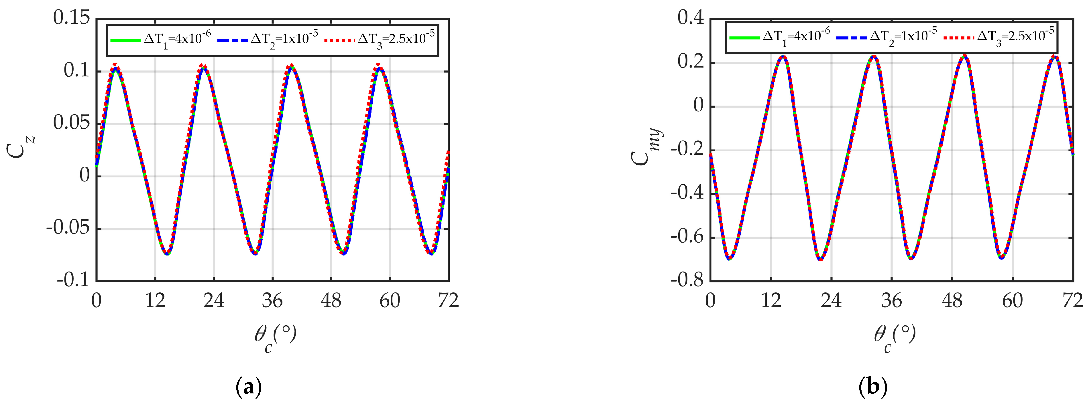
In the time-step independence study, three time steps were chosen, and the inner iteration number was set to 20 according to Bhagwandin [29]. The corresponding rolling angles for coning and spinning at different time steps are as follows: θ c = 0.0245 ° , θ s = 0.1226 ° , θ c = 0.0613 ° , θ s = 0.3065 ° ; θ c = 0.1533 ° , and θ s = 0.7663 ° . Figure 4a,b shows the transient lateral force and yawing moment coefficients in one-fifth of the coning motion cycle, during which the projectile spins one cycle in the quasi-body-fixed coordinate system. The transient results of T 1 and T 2 are basically coincident, and the relative errors of the time-averaged value are within 5%. However, the transient lateral force obtained with T 3 deviates from those of the other two time steps. Because the lateral force and yawing moment are small, subtle changes must be accurately and efficiently captured, so T 2 was chosen for further calculations.

3.3.2. Validation of Unsteady Numerical Method

Spin-Induced Lateral Force and Yawing Moment

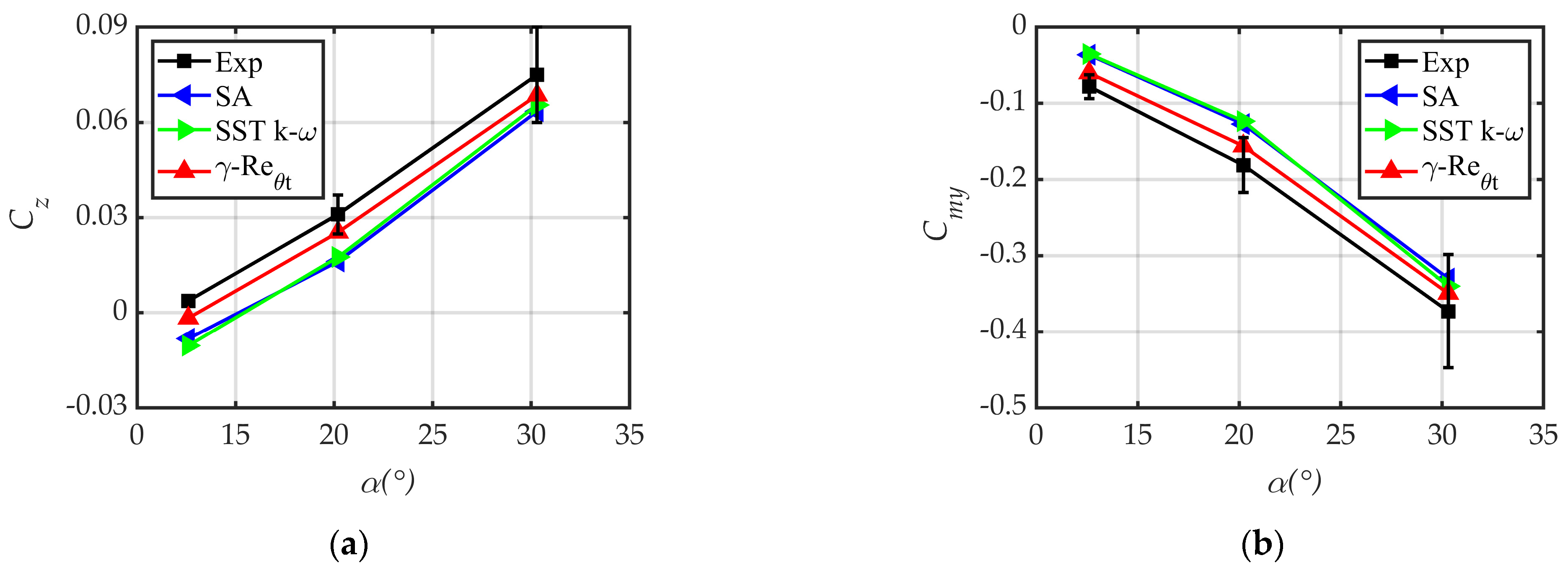
Computations were carried out for Ma = 2.5 and ω ¯ s = 0.05 , and the CFD results were compared with the experimental data obtained by the Arnold Engineering and Development Center (AEDC, USA) [28]. Figure 5a,b provides the time-averaged lateral force and yawing moment coefficients at the AoAs, and the results of different turbulence models are compared. The spin-induced Magnus force and moment are small and only one-hundredth to one-tenth of the normal force and pitching moment; a 20% difference between experimental data and numerical results is considered good enough [30].
It can be seen that the CFD results of the γ R e θ t transition model are located between the results of other turbulent models and experimental data. Except for the case at α = 12.6 ° , the relative errors between the CFD and experimental results are kept within 20% for such small quantities. At R e d = 2.57 × 10 5 , the flow around the projectile is mainly laminar and induces a smaller –z body lateral force compared with the turbulent flow. Therefore, the γ R e θ t transition model was used to obtain a more accurate flow field and aerodynamic characteristic results.

Pitch Damping Characteristics

The pitch-damping coefficient is a basic criterion for evaluating the unsteady numerical method and flight characteristics. Here, the pitch damping coefficient was computed through the forced oscillation of the projectile about the Z axis. Detailed aerodynamic and structural conditions referred to and were deduced from Bhagwandin as follows: R e d = 2.11 × 10 6 , Ma = 2.0, 2.5, 3.0, P = 101325   P a , T = 293.15   K , I x = 0.0064   k g∙m2, I y = 0.0354   k g∙m2, m = 2.48 kg, X ¯ c g = 0.48. The pitching oscillation parameters are A = 0.25 ° , α 0 = 0 ° , N = 200 , and k d = 0.1 . The first-order Taylor expansion of the moment coefficient in planar motion can be written as follows [31]:
C m t = C m 0 + C m α α t + C m q ω q t D / 2 V + C m α ˙ α ˙ t D / 2 V
where C m 0 is the static moment coefficient at zero AoA, and C m α is the moment coefficient induced by the AoA. C m q is the moment coefficient induced by the pitch rate. In this study, forced planar pitching was achieved, and the pitch rate and AoA rate were equal:
ω q = α ˙
By integrating and simplifying Equation (13) over a period, the pitch damping coefficient can be expressed as follows:
C m q + C m α ˙ = 2 V / π A D 0 T C m t c o s 2 V k d t / D d t
The detailed derivation process can be found in [31].
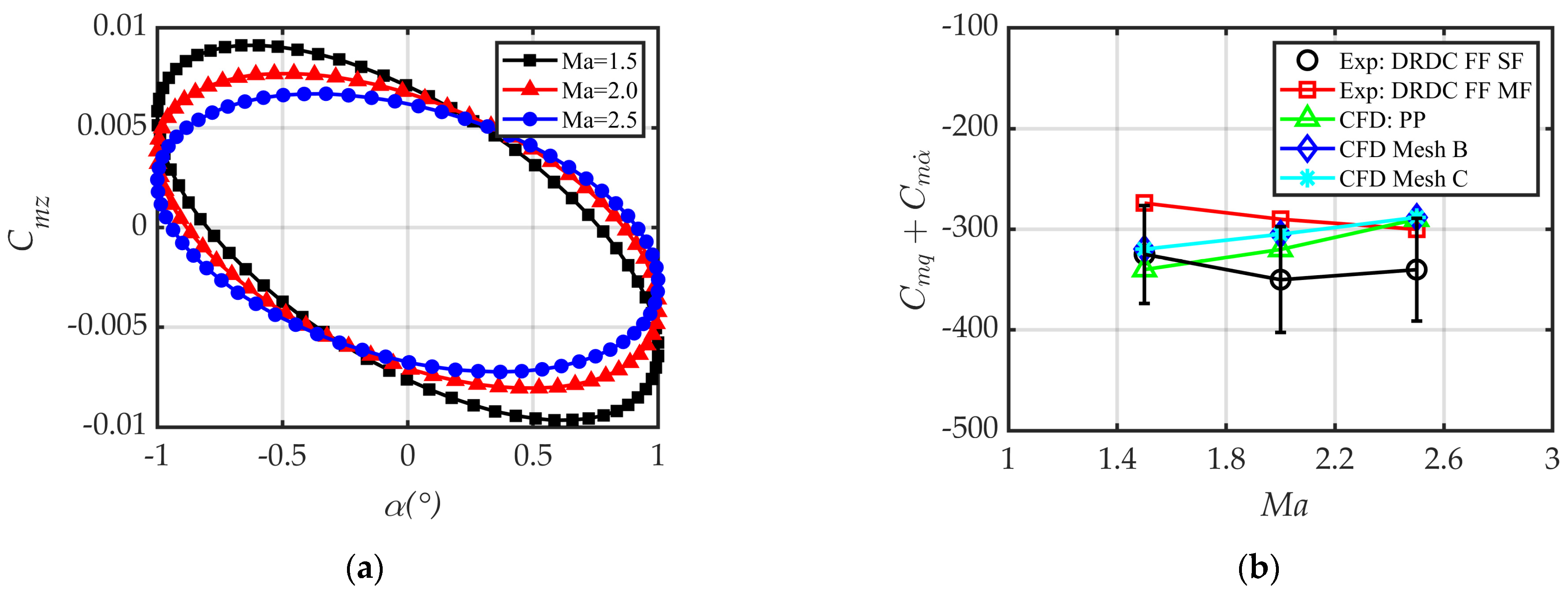
Figure 6a shows the transient pitching moment coefficient in an oscillation cycle at different Mach numbers. The periodical ring becomes flattened as the Mach number increases, and the pitch-damping coefficient can be calculated using Equation (15). In Figure 6b, the calculated pitch-damping coefficients are compared with the computational (CFD: PP—planar pitching) and experimental (FF SF—free flight single fit; FF MF—free flight multiple fit) results obtained from the Defence Research and Development Canada (DRDC) [31]. The results for Mesh B and Mesh C are essentially the same, and their variation tendencies agree with that of CFD: PP. Moreover, the computed results are within a 15% error range of the experimental data.

Lunar Coning Induced Lateral Force and Yawing Moment

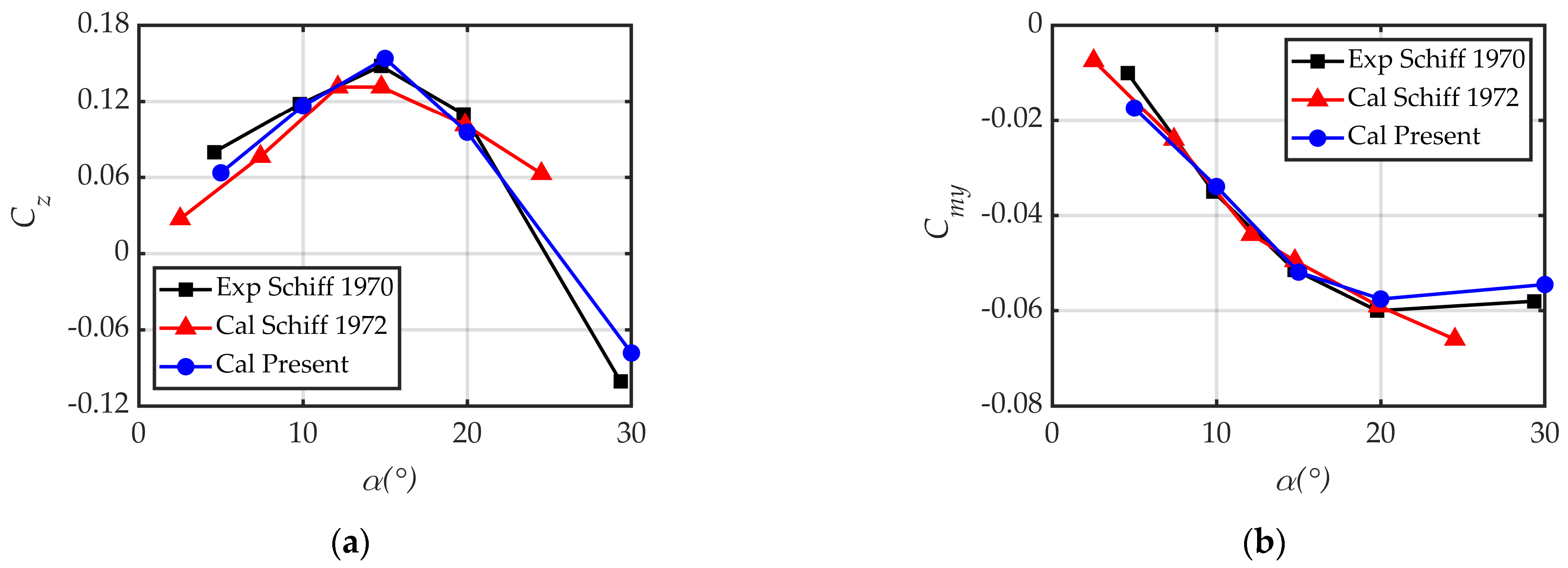
A 10° half-angle cone was chosen to validate the lateral force and yawing moment of lunar coning motion. The detailed aerodynamic and structural conditions that were deduced from [32,33] are as follows: R e L = 6.66 × 10 6 , Ma = 2.0, P = 19,339 P a , T = 173 K , ω ¯ c = 0.024 , ω ¯ s = 0 , T = 1 × 10 5   s , l = 0.58 m, and X ¯ c g = 0.61. The computation domain was similar to that in Figure 3a. Figure 7 shows the lateral force and yawing moment coefficients at α ( 0 ° , 30 ° ) . The results of this computation matches well with the experimental and computational results obtained in [32,33].
In short, the unsteady aerodynamic characteristics of the AFF projectile in supersonic conditions can be accurately and efficiently computed combining Mesh B, T 2 = 1 × 10 5   s , and the γ R e θ t transition model.

4. Results and Discussion

4.1. Effect of AoA

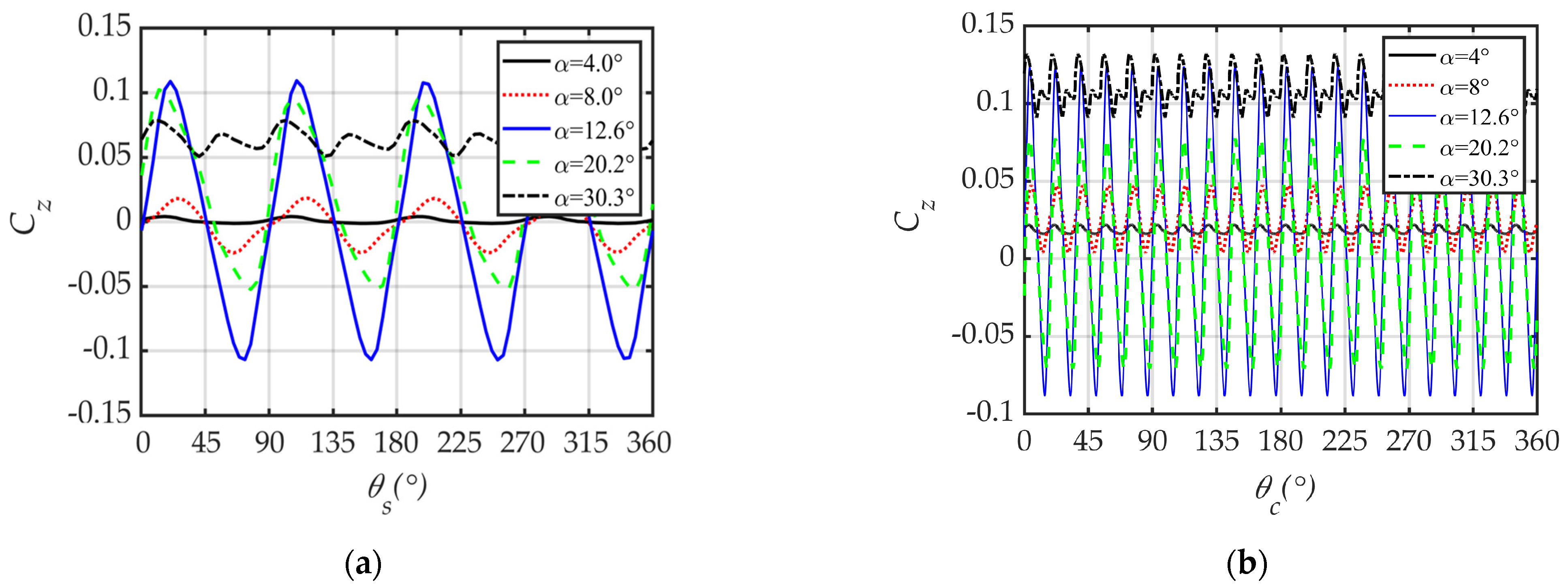
The effects of the AoA, which is equal to the cone angle, on the aerodynamic characteristics were investigated. Figure 8 gives the transient total lateral force coefficient of the spinning projectile (Figure 8a) and the spinning–coning coupled projectile (Figure 8b) at different AoAs. In Figure 8a, the curves have four fluctuation periods, the number of which is the same as the fin number. The transient amplitude of the coefficient first increases and then decreases with the AoA, reaching its maximum value at α = 12.6 ° . The transient coefficient at α = 30.3 ° is always positive. The transient lateral force of the projectile body and fins affected by the interference of fin leading edge shock is mainly responsible for the above variation tendency. A detailed explanation can be found in Figures 8, 13, and 15 in [8]. In Figure 8b, according to ω ¯ c : ω ¯ s = 1 : 6 (see Table 2), the projectile spins six cycles during a coning period in the inertial coordinate system, while it spins five cycles in the quasi-body-fixed coordinate system. Therefore, the variation tendency of the curves is similar to that of curves in Figure 8a, and the curves have twenty ( 4 × 5 = 20 ) fluctuation periods. Compared with Figure 8a, the data in Figure 8b show that the coning motion has little effect on the transient amplitude of the lateral force but has an obvious influence on the time-averaged values, which might result from the coning motion induced F d r a g term.
Figure 9 shows the variation in the time-averaged total force/moment coefficients with the AoA. As shown in Figure 9a,b, the normal force (the aerodynamic force in the plane of AoA pointing to OYB direction) and pitching moment (the moment of normal force on the center of mass) coefficients are basically the same for the two motions, while the coupled motion decreases the coefficients within 5%. In Figure 9c, the lateral force coefficient for the spinning projectile changes from negative to positive with the AoA, though for spinning–coning coupled projectile, it is always positive and shows strong nonlinear characteristics. At small and moderate AoAs, the magnitude and derivative of the lateral force increase obviously due to the coning motion. In Figure 9d, the coning motion significantly increases the yawing moment, the derivative of which reaches five times the value of the spinning motion when α 8 ° . This may potentially impact flight stability.
To further clarify the variation in the lateral force coefficient in Figure 9c, Figure 10 shows the variation in the time-averaged component lateral force coefficients with AoA. In Figure 10a, the body lateral force coefficient of the spinning projectile is always negative, and its magnitude first increases and then decreases. The body lateral force coefficient of the spinning–coning coupled projectile changes from positive to negative at about α = 8 ° , and its magnitude increases significantly at α = 20.2 ° . In Figure 10b, the magnitude and derivative of the Fin 1 lateral force coefficient increase due to the coning motion. In general, due to the influence of coning motion, the lateral force of the projectile body presents a stronger nonlinearity with AoA, and the lateral force of Fin 1 is obviously strengthened. Thus, the total lateral force of the projectile with spinning–coning coupled motion is shown to vary uniquely with the AoA. A detailed explanation can be found in Figure 16 related to asymmetric expansion waves. It should be noted that the body’s lateral force strengthens at α = 20.2 ° is opposite to that of Fin 1, forming a couple that produces yawing moment (Figure 9d) while maintaining quite a small resultant force value (see Figure 9c).

4.2. Effect of Non-Dimensional Spin Rate

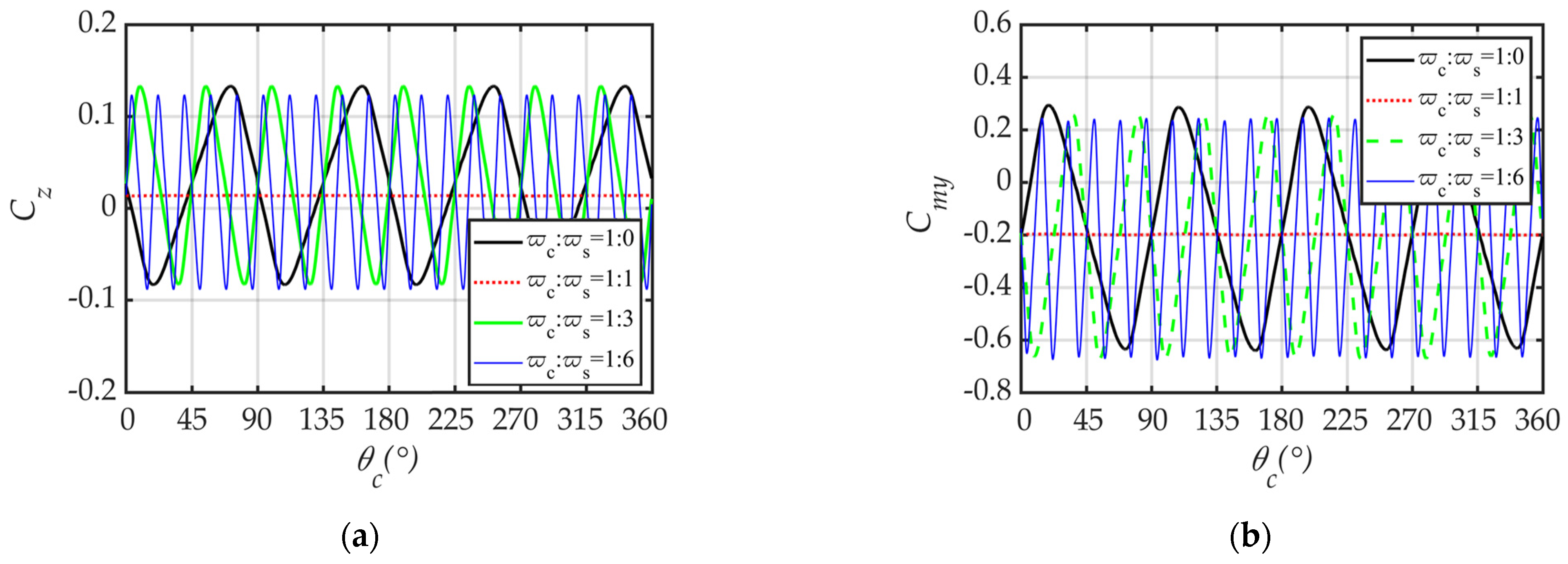
The effect of the non-dimensional spin rate on the lateral force and yawing moment characteristics is discussed. In the inertial coordinate system, ω ¯ c : ω ¯ s = 1 : 0 indicates that only coning motion exists; there is no spinning motion. ω ¯ c : ω ¯ s = 1 : 1 indicates that the projectile spins a cycle in a coning period, namely, it demonstrates lunar coning motion. The normal force and pitching moment coefficients are nearly unchanged at different spin rates and are no longer given. Figure 11 shows the transient total lateral force and yawing moment coefficients at α = 12.6 ° with different spin rates. According to ω ¯ c : ω ¯ s = 1 : 0 , 1 : 1 , 1 : 3 , 1 : 6 (see Table 2), in a quasi-body-fixed coordinate system during a coning period, the projectile spins −1, 0, 2, and 5 cycles about its longitudinal axis, and the fluctuation periods of transient coefficients are 4, 0, 8, and 20, respectively. The additional AoA induced by the spin and cone rates is relatively small compared with the AoA, and the amplitudes of the transient lateral force and yawing moment coefficients are basically the same at different spin rates except for lunar coning motion.
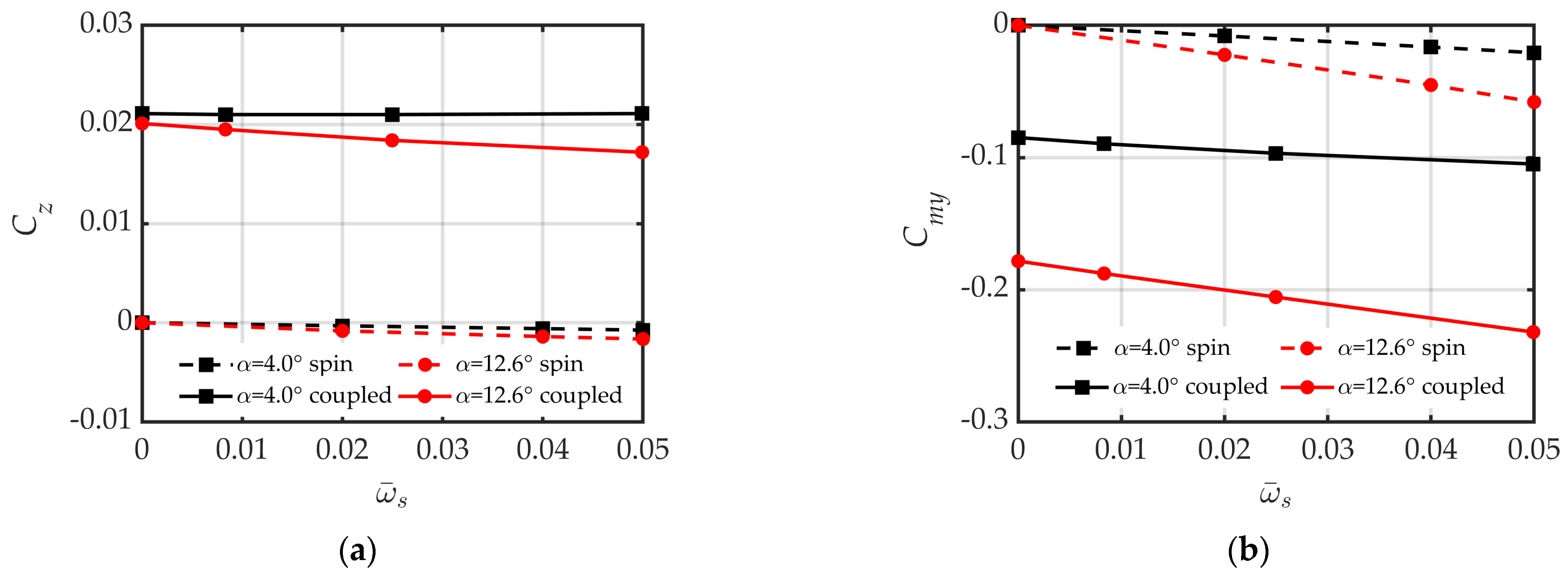
Figure 12 shows the variation in the time-averaged total lateral force and yawing moment coefficients with the non-dimensional spin rate at α = 4 ° and α = 12.6 ° , and the value of the horizontal coordinate is in the inertial frame. It can be seen that the time-averaged lateral force and yawing moment vary linearly with ω ¯ s , and the values of the spinning–coning coupled projectile are obviously larger than those of the spinning projectile. It should be noted that ω ¯ s = 0.008 3 ˙ corresponds to the case for ω ¯ c : ω ¯ s = 1 : 1 , where the spin rate is zero relative to the quasi-body-fixed frame. In this situation, the lateral force originates from the F d r a g term (see Figure 1c), indicating that the coning induced F d r a g , which is obviously stronger than the spin-induced Magnus effect and plays a dominant role in producing lateral force. At different AoAs, the coupling of the coning-induced F d r a g and the spin-induced Magnus characteristics leads to a complicated variation in the total lateral force in Figure 9c.

4.3. Effect of Non-Dimensional Cone Rate

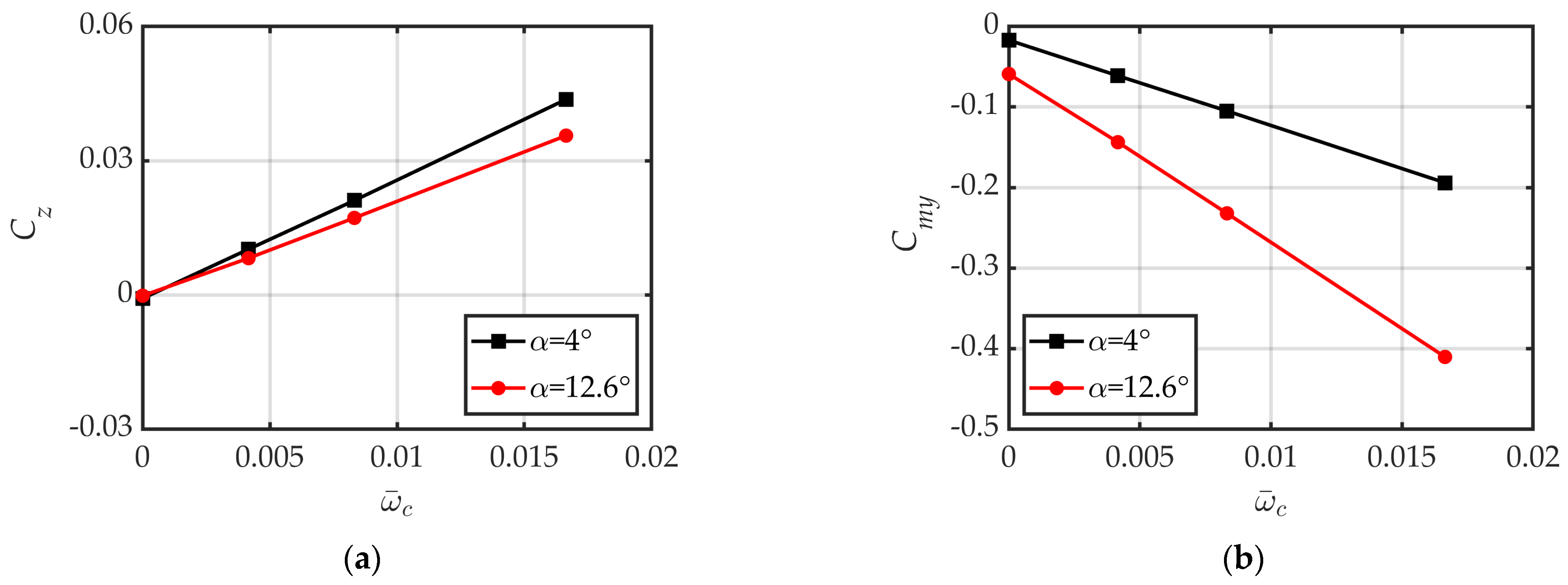
The effect of the non-dimensional cone rate on the lateral force and yawing moment characteristics is discussed. Figure 13 provides the time-averaged total lateral force and yawing moment coefficients at different cone rates; ω ¯ c : ω ¯ s = 0 indicates the case with only spinning motion. It can be seen that the magnitude of the coefficients increases as the cone rate increases, and the slope of the curves is obviously larger than in Figure 12. This indicates that the cone rate has a more significant influence on the lateral force and yawing moment compared to the spin rate; namely, the F d r a g term plays an important role. The lateral force coefficients at α = 12.6 ° are smaller than those at α = 4 ° in Figure 13a, while the opposite is true for the yawing moment coefficient in Figure 13b, indicating that the pressure center of lateral force is closer to the projectile base and is more sensitive to the cone rate at larger AoAs and that the lateral force and yawing moment produced by the coupled motion around the tail sections are more obvious.

4.4. Mechanism of Coning Motion on Lateral Force

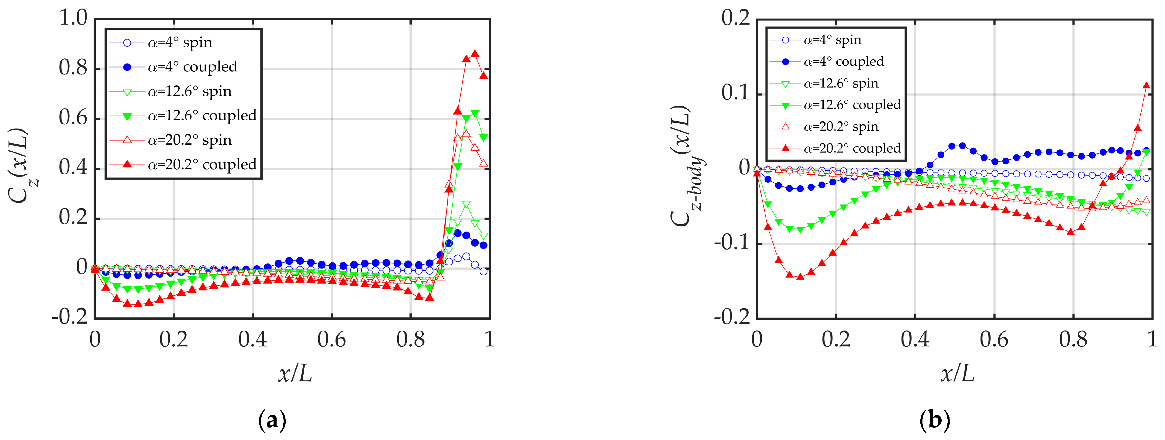
Figure 14 shows the time-averaged distributed lateral force coefficient along the projectile’s longitudinal axis for spinning and spinning–coning coupled motions at ω ¯ c : ω ¯ s = 1 : 6 . Figure 14a provides the distributed total lateral force coefficients, which show obvious differences between the two types of motion at the forebody and tail. Figure 14b shows the distributed body lateral force coefficients, which can be regarded as an enlarged view of Figure 14a. For forebody x / L 0.4 , the lateral force induced by the spinning–coning coupled motion negatively increases with the AoA, and its magnitude is much larger than that induced by the spinning motion. When x / L > 0.4 and α = 4.0 ° , the spinning–coning coupled motion induces a + z lateral force in the opposite direction to the force induced by the spinning motion. At aftbody x / L 0.8 and α 12.6 ° , the coning-induced lateral force positively increases and changes direction near the base. For spinning–coning coupled motion, the projectile profile spins around point P (see Figure 3a) and has transient circular motion velocity in addition to the surface spin rate. Therefore, additional mechanisms should be considered for the variation in lateral force; these are discussed in detail below.
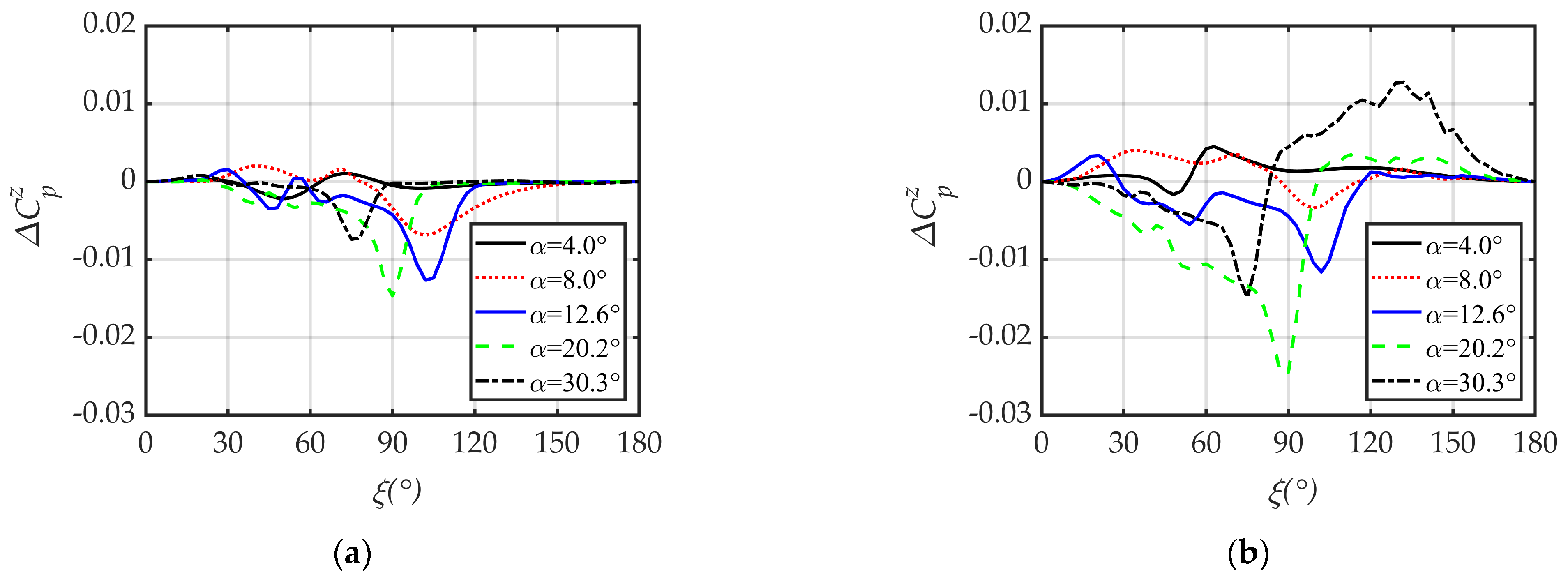
First, the mechanism of slender body lateral force was investigated. Figure 15 shows the pressure difference between the right- and left-side bodies of the AoA plane (from the base view) along the circumferential angle ξ at the aftbody profile x/L = 0.7 (before the tail’s leading edge). Figure 15a,b presents the spinning and spinning–coning coupled motions cases, respectively. In Figure 15b, when α = 4.0 ° , the curve shows a positive–negative–positive variation at leeward ξ ( 30 ° , 90 ° ) , and the values of the curve are basically positive at windward ξ ( 90 ° , 180 ° ) , both of which show a positive shift compared with the case in Figure 15a. When α = 12.6 ° , the peak and valley values change to some extent but are not dominant at leeward ξ ( 0 ° , 70 ° ) . At windward ξ ( 90 ° , 180 ° ) , the curves are nearly the same, reaching the minimum value around ξ = 103 ° . The profile lateral forces for the two motions are similar. When α = 20.2 ° , an obviously negative pressure difference appears at leeward ξ ( 0 ° , 90 ° ) , resulting in a much stronger lateral force compared to the case in Figure 15a. When α = 30.3 ° , the coning-induced positive pressure difference at windward ξ ( 90 ° , 180 ° ) is quite unique.
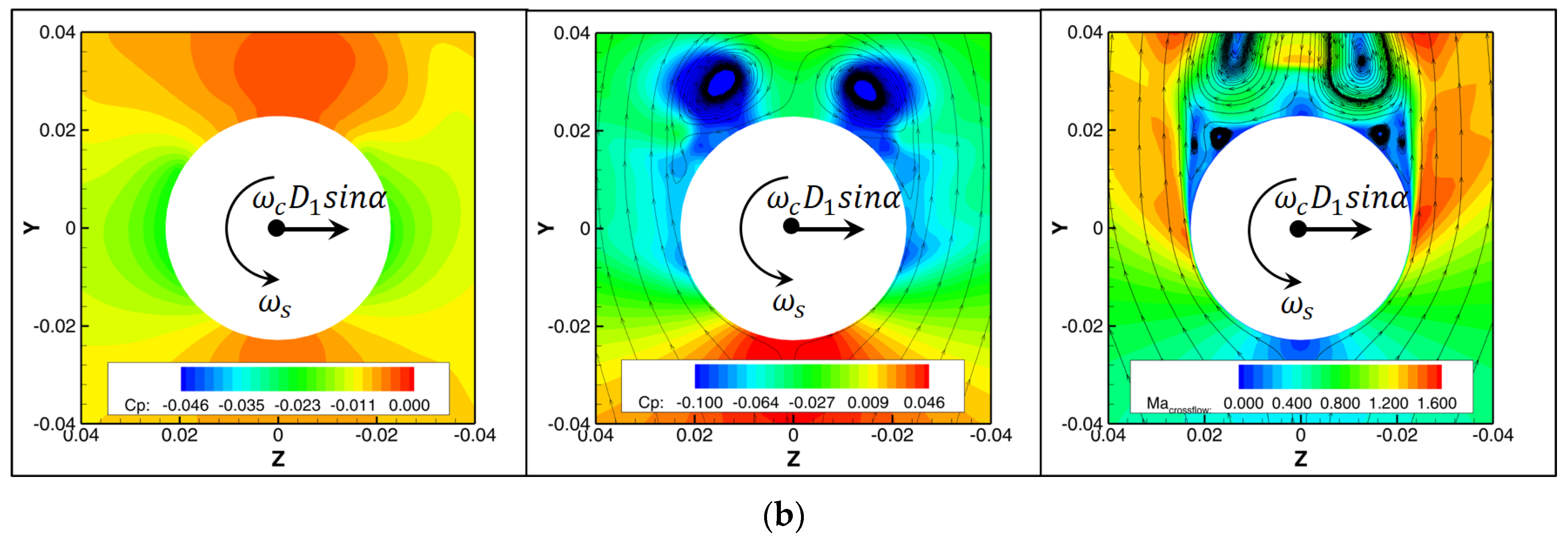
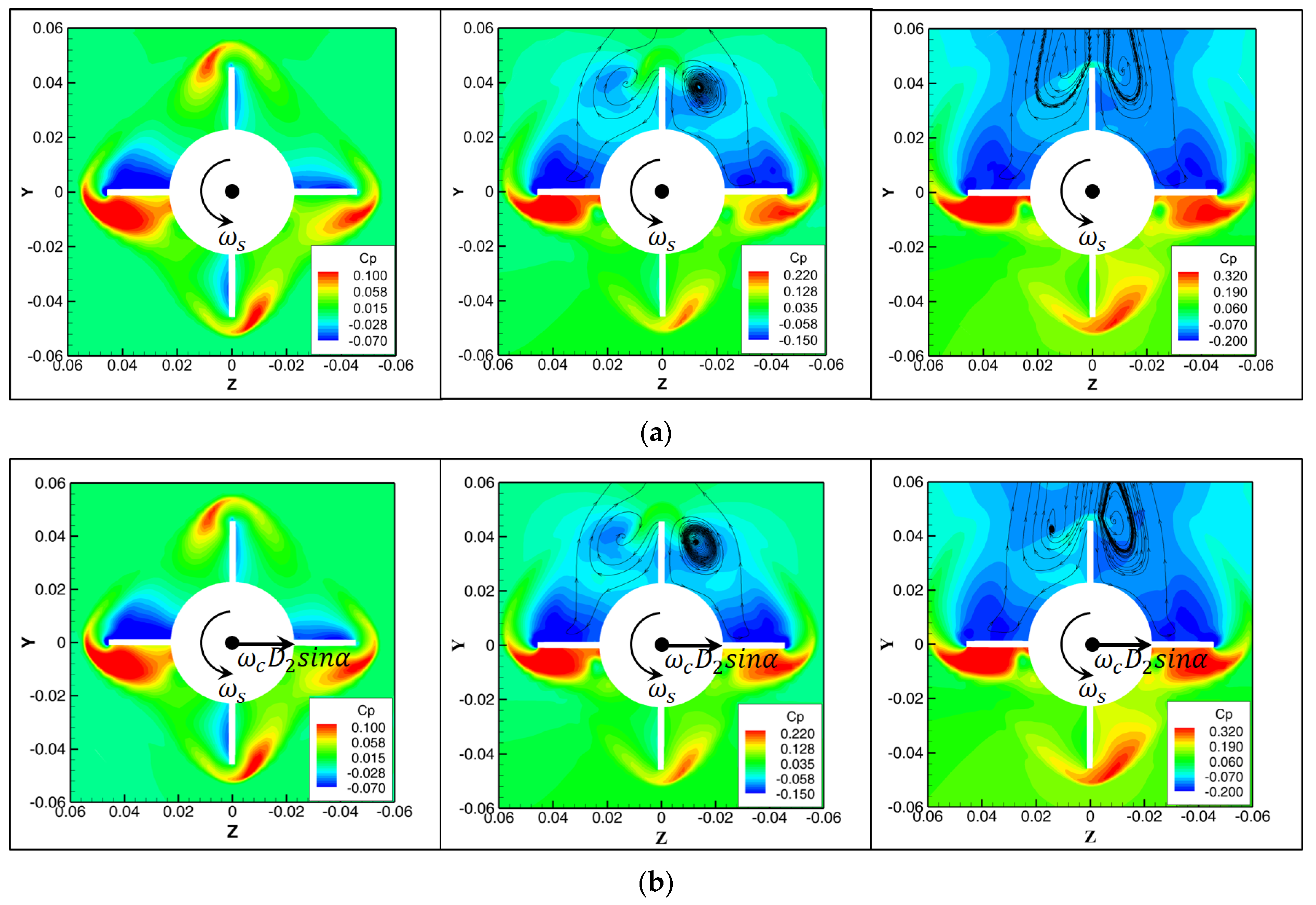
Figure 16 shows the pressure contours and crossflow streamlines at x/L = 0.7. Figure 16a presents the spinning motion case. At α = 4.0 ° , the left-side surface spin rate decreases the crossflow velocity due to viscosity, and the surface pressure increases; the right-side surface spin rate compensates for the crossflow velocity, and the surface pressure decreases. Thus, a -z lateral force is induced with little flow separation. At α = 12.6 ° , when the left-side crossflow cannot overcome the viscous drag force induced by the surface spin rate, the crossflow separation occurs with decreasing velocity and increasing pressure; the right-side surface spin rate compensates for the adverse pressure gradient, and the crossflow separation is delayed due to increasing velocity and decreasing pressure. An obvious negative lateral force is induced by the asymmetric flow separation and secondary vortices. At α = 20.2 ° , the crossflow velocity increases and the expansion wave forms, which strengthens the contribution of asymmetric flow separation and weakens the contribution of asymmetric vortices to the -z lateral force.
Figure 16b presents the spinning–coning coupled motion case. The transient circular velocity induced by the coning motion indicates that the profile has an additional positive sideslip angle. When α = 4.0 ° , β e = 0.066 ° . The right-side surface is equivalent to windward and the surface pressure increases, while the left-side surface is equivalent to leeward and the surface pressure decreases, resulting in a +z lateral force which changes direction compared to the spinning motion case. When α = 12.6 ° , asymmetric flow separation is still the main source of lateral force, and the right vortex approaches the surface while the left vortex retreats far away from the surface, resulting in a slight variation in the leeward lateral force distribution, the magnitude of which is equivalent to that of the spinning motion. When α = 20.2 ° , combining the influence of the spin rate, the AoA, and β e = 0.309 ° , the right-side crossflow velocity increases and reaches the speed of sound; thus, a strong expansion wave is produced and decreases the local pressure. On the contrary, the left-side crossflow shows no obvious change compared with the spinning motion case, resulting in a large -z lateral force. With further increase in the AoA, the expansion waves strengthen on both sides, inducing a large low-pressure region in leeward and weakening the contribution of asymmetric flow structures to the lateral force. It should be noted that the effective sideslip angle increases with the AoA and mostly contributes to windward +z lateral force, while the leeward lateral force is determined by the effective sideslip angle, flow separation, separation vortices, and expansion waves in combination.
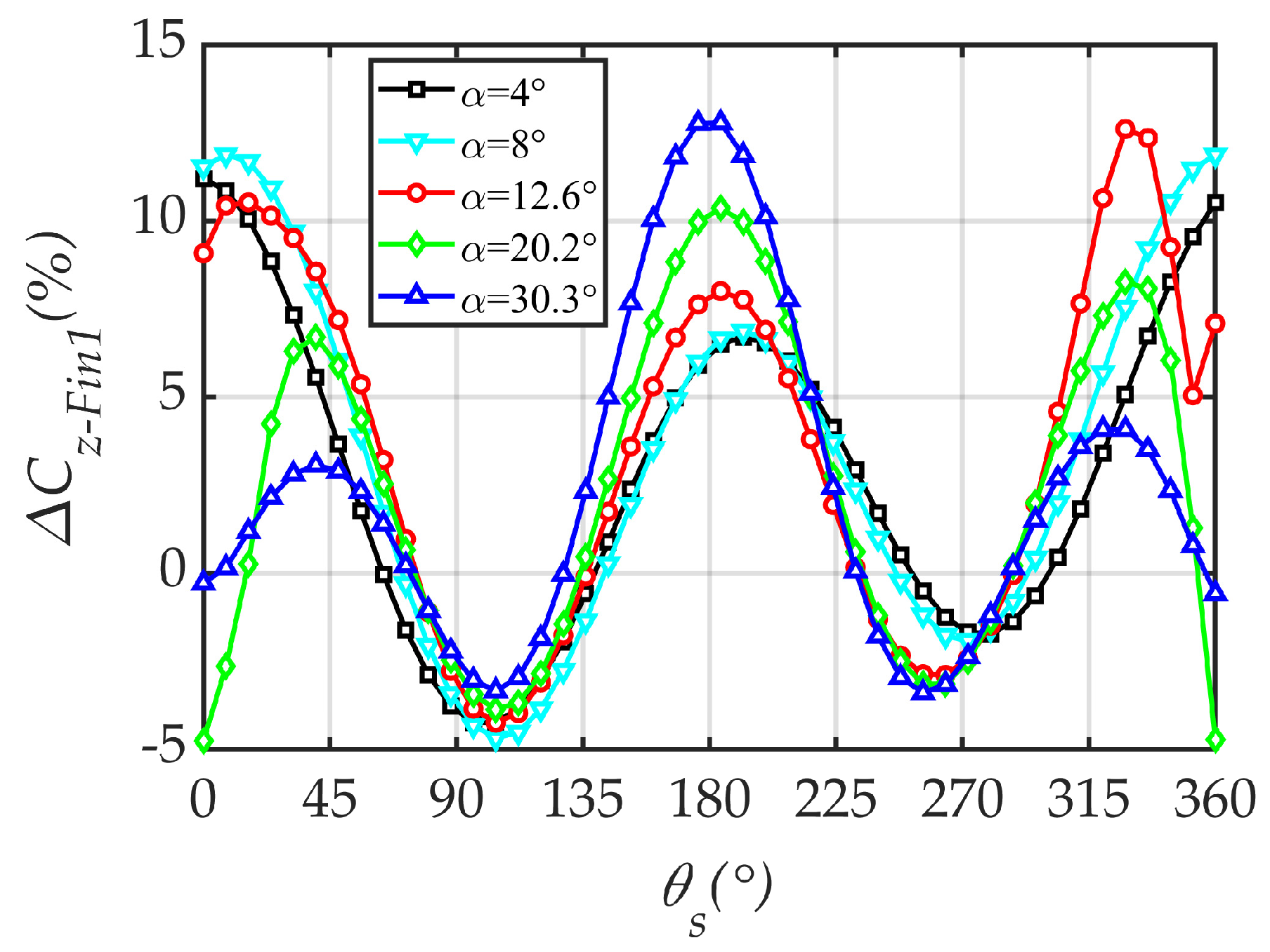
The mechanism of the fin lateral force was also investigated. The fin lateral force in one-fifth of a coning period, which is exactly one spinning period, was investigated. Figure 17 shows the influence of coning motion on the Fin 1 lateral force. The y coordinate can be expressed as follows:
C z F i n 1 = C z F i n 1 c o u p l e d C z F i n 1 s p i n m a x C z F i n 1 c o u p l e d × 100 %
The numerator indicates the subtraction of the Fin 1 lateral force of the spinning motion from that of the spinning–coning coupled motion. The denominator is the maximum Fin 1 lateral force of spinning–coning coupled motion at each AoA. In Figure 17, when Fin 1 is located in leeward ξ 0 ° , 90 ° and ξ 270 ° , 360 ° , the contribution of the coning motion to the Fin 1 lateral force firstly increases and then decreases, reaching the maximum value at α = 12.6 ° , while a negative contribution even occurs at α = 20.2 ° . When Fin 1 is located in windward ξ 90 ° , 270 ° , the contribution of the coning motion increases with the AoA.
One characteristic position, θ s = 0 ° , shown in Figure 17, was chosen for flow structure analysis. Figure 18 shows the pressure contours and crossflow streamlines at x/L = 0.962, and the spin rate and the transient circular motion velocity induced by the coning motion are also marked. Figure 18a shows the flow field of the spinning motion. Because of the spin rate, the lateral forces of the windward fin at θ s = 180 ° and the leeward fin at θ s = 0 ° are in opposite directions. With an increase in the AoA, the leeward flow structure changes drastically, having a complicated impact on the fin lateral force during spinning.
Figure 18b shows the flow field of the spinning–coning coupled motion. When α = 4.0 ° , the coning motion induced β e = 0.154 ° increases the right-side surface pressure and decreases the left-side surface pressure of the leeward fin, contributing to the transient +z lateral force and weakening the -z lateral force of the upper fin induced by the spinning motion. As for the windward fin, both the coning and spinning motions contribute to the transient +z lateral force. Therefore, the transient lateral force of the windward fin is stronger than that of the leeward fin, and the relative contribution of the coning motion to the fin transient lateral force is stronger on the leeward. When α = 12.6 ° and β e = 0.480 ° , the leeward fin is located between the two separated shedding vortices, and both sides are surrounded by a low-pressure region; thus, the influence of β e is limited. It should be noted that the leeward fin just enters the right side shedding vortex when θ s 330 ° . The left-side of the fin is in the low-pressure environment while the right-side of the fin is in a relatively high-pressure environment induced by β e ; thus, the contribution of the coning motion to the +z lateral force is the most obvious (see Figure 17). When α = 20.2 ° and β e = 0.760 ° , on the one hand, the right side shedding vortex strengthens and leans against the right side of the leeward fin due to the coning motion, decreasing the local pressure; on the other hand, the left-side shedding vortex breaks and dissipates, increasing the local pressure. Therefore, the coning motion contributes to the transient –z fin lateral force, which is also affected by forebody asymmetric flow. With a further increase in the AoA, the leeward body becomes a low-pressure region due to the shedding effect, and the contribution of the coning motion to the leeward fin lateral force degrades.

4.5. Flight Response Analysis

4.5.1. Modified Expression of Yawing Moment

In Equation (9), C m y , which is a linear function of the AoA and non-dimensional spin rate, is calculated as follows:
C m y = f α , ω ¯ s = C m y α , ω ¯ s α ω ¯ s
Through the above investigation, it was established that the time-averaged lateral force and yawing moment vary linearly with the non-dimensional spin rate and cone rate for the spinning–coning coupled motion when α 8 ° , while the variation in other aerodynamic parameters can be neglected. At α = 4 ° , the discrete C m y and the fitting plane obtained through the least square method are shown in Figure 19. Therefore, the C m y of the spinning–coning coupled projectile can be modified as a linear function of the AoA, non-dimensional spin rate, and non-dimensional cone rate as follows:
C m y = f α , ω ¯ s , ω ¯ c = C m y α , ω ¯ s α ω ¯ s + C m y α , ω ¯ c α ω ¯ c
where C m y α , ω ¯ s = C m y α ω ¯ s and C m y α , ω ¯ c = C m y α ω ¯ c . Replacing Equation (17) with Equation (18), the term Q in Equation (9) can be revised as follows:
Q = ρ S / 2 m C L α K x 2 C m y α , ω ¯ s + ω ¯ c / ω ¯ s C m y α , ω ¯ c

4.5.2. Angular Motion Characteristics

The structural and aerodynamic parameters necessary for the analysis of angular motion characteristics are given in Table 5. In this table, the reference length of the aerodynamic parameters is changed from the projectile’s diameter to its length, and the structural parameter is obtained by combining these parameters [31]. Moreover, the aerodynamic parameters are converted to the values in the velocity coordinate system, for example, a minus sign is added to the pitching moment. It should be noted that the cone rate has an obvious effect on the yawing moment, which might affect flight stability.
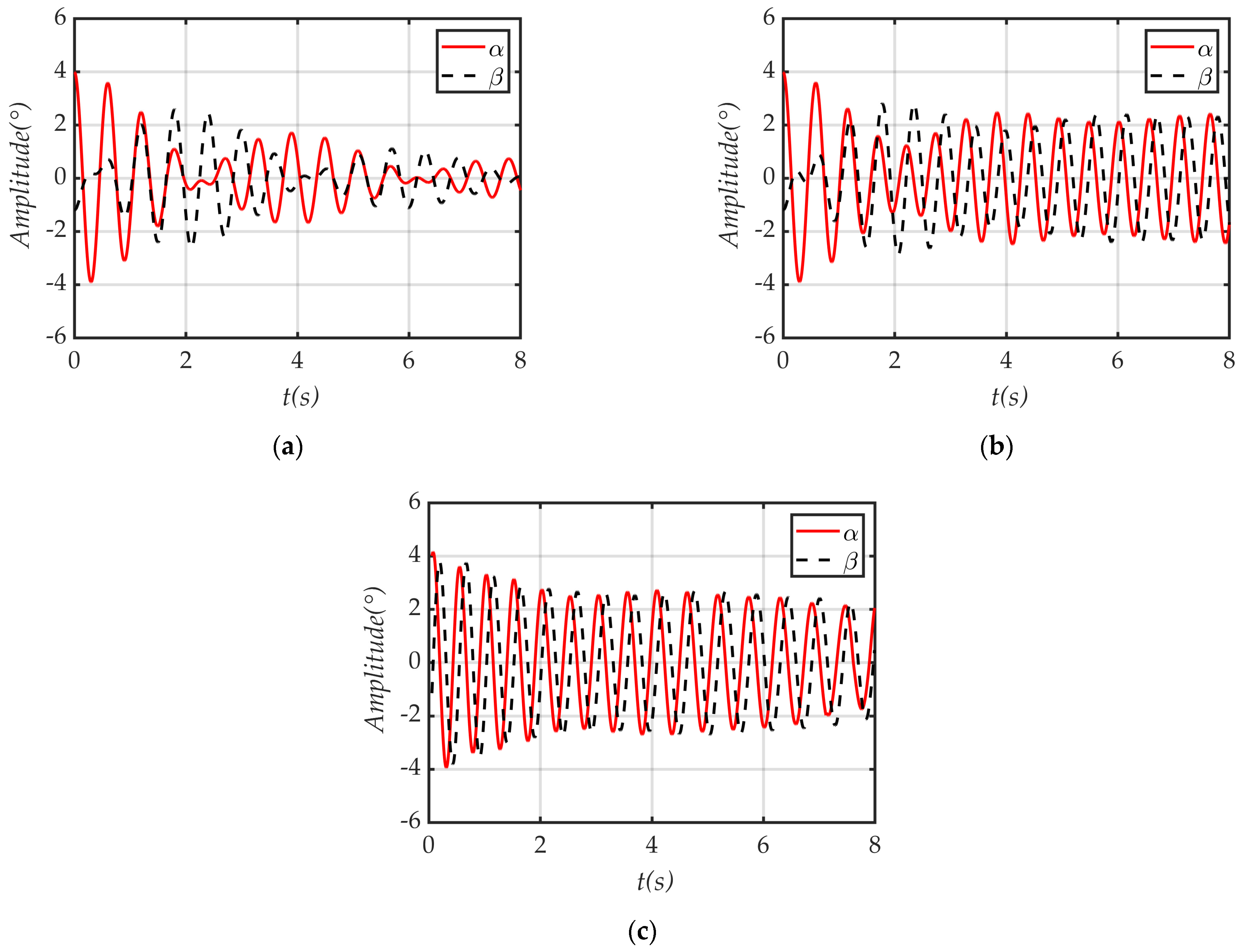
ω c = 4 π   r a d / s and ω s = 13 π   r a d / s were chosen for detailed analysis. The initial disturbances are η 0 = 4 1.2 i ° / s and η 0 = 0.0 0.0 i ° / s . Substituting the parameters in Table 5 into Equations (10) and (11), the response of the complex angle of attack is shown in Figure 20. In Figure 20a, the angles of attack and sideslip decay gradually to zero with the aerodynamic parameters of the spinning motion, indicating stable flight. In Figure 20b, the angles of attack and sideslip increase slightly with the aerodynamic parameters of spinning–coning coupled motion, and divergence might occur. To validate the results of the angular motion theory, a coupled 3-DoF CFD-RBD calculation was performed with a constraint XYZ displacement, and the result is shown in Figure 20c. The attack and sideslip angles maintain a certain amplitude and decrease slowly, which is similar to the case shown in Figure 20b.
In Figure 20b, the response of the complex angle of attack is obtained based on the angular motion theory, in which only the initial conditions and aerodynamic parameters are accounted for and the decay of the spin rate is not considered. The curves in Figure 20c were obtained from the coupled CFD-RBD calculation, during which the spin rate reduced and the magnitude of the yawing moment decreased. Therefore, the amplitude of the curve in Figure 20c does not completely match that in Figure 20b. The reason for the reduction in the spin rate in the CFD-RBD calculation is that the computational model has uncanted fins. For a projectile with canted fins, the response of the complex angle of attack from the angular motion theory and CFD-RBD calculation results should be consistent.
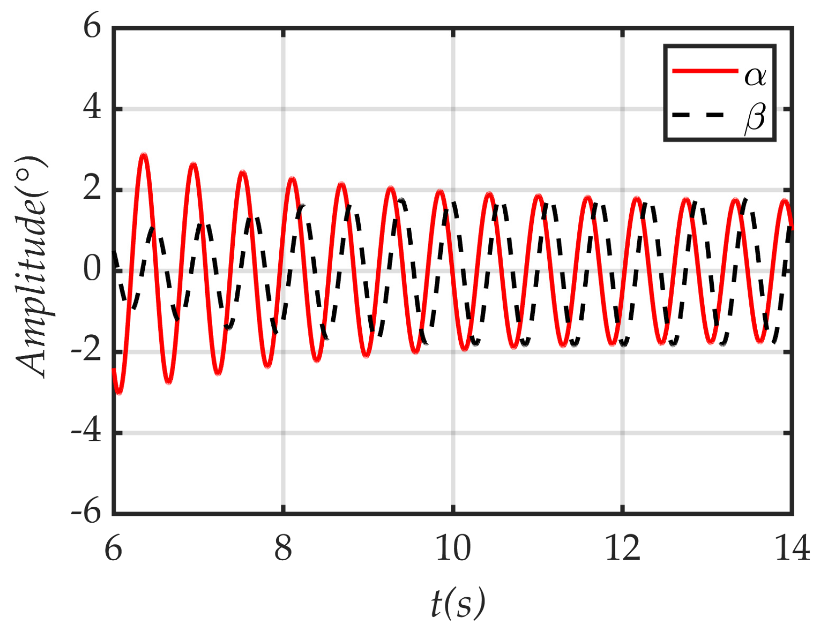
Using the AoA, spin rate, and cone rate obtained via the 3-DoF calculation, with t = 6 s as an initial conditions, namely, ξ 0 = 2.4 + 0.5 i ° / s , ξ 0 = 0.034 0.014 i ° / s , ω s = 2.14 π   r a d / s , and ω c = 3.52 π   r a d / s , and combining the aerodynamic parameters of spinning–coning coupled motion, the solution of Equation (11) is given in Figure 21. It can be seen that the complex AoA response values obtained using the revised angular motion theory and the 3-DoF calculation after t = 6 s are both convergent, with similar amplitudes. In general, a more realistic complex AoA response can be found using the modified aerodynamic parameters and the revised angular motion theory.

5. Conclusions

A method of numerically simulating flow over a spinning–coning coupled projectile was developed. The variation in the transient and time-averaged lateral force and yawing moment characteristics with the AoA, non-dimensional spin rate, and non-dimensional cone rate was investigated, and the flow mechanism of the coning motion on the lateral force and yawing moment was revealed, resulting in a modification of the yawing moment term in the angular motion theory. The response of the complex AoA following an initial disturbance was investigated and validated using a coupled 3-DoF CFD-RBD calculation. The results indicate the following:
Compared with the spinning motion, at a small AoA, the coning motion induces a positive lateral force on both the projectile’s body and fins, multiplying the magnitudes of the total lateral force and yawing moment. At a moderate AoA, coning motion induces a larger negative lateral force on the body, while the fin lateral force is positive, maintaining quite a small resultant total force while forming a couple that produces a yawing moment. At a large AoA, coning motion mainly contributes to the fin lateral force and yawing moment.
For the projectile body, at a small AoA, the effective sideslip angle induced by the coning motion alters the direction of lateral force. At moderate and critical AoAs, asymmetric expansion waves make an additional contribution. For windward projectile fins, the coning motion-induced angle of the sideslip increasingly contributes to the lateral force with the AoA; for leeward projectile fins, both the effective sideslip angle and asymmetric vortices contribute to the lateral force. In particular, the negative contribution to the lateral force can be observed when the fin just enters one separation vortex.
According to the aerodynamic analysis of a projectile experiencing spinning–coning coupled motion, the time-averaged lateral force and yawing moment vary linearly with the AoA, non-dimensional spin rate, and non-dimensional cone rate at small and moderate AoAs. By modifying the expression of the yawing moment in the traditional angular motion theory, the response of the complex angle of attack can be made more consistent with the results of CFD-RBD calculations, which is of great significance to stability analysis.
Given that the coning motion always occurs for a spinning projectile during flight and is closely related to the projectile’s structural and aerodynamic parameters, an aerodynamic optimization design can hardly be achieved by simply reducing the cone rate. When designing the spin rate, it is necessary to evaluate the spinning–coning coupling effect on the dynamic stability of a projectile. The coupled CFD-RBD calculation is expensive, time-consuming, and unsuitable for early aerodynamic design. Therefore, the semi-numerical and semi-theoretical methods developed in this study could be an efficient and reliable alternative.

Author Contributions

Conceptualization, J.Y., S.J. and H.M.; methodology, J.Y. and S.J.; validation, J.Y. and J.Z.; formal analysis, J.Y., Y.H. and J.L.; investigation, J.Z. and H.M.; writing—original draft preparation, J.Y. and Y.H.; writing—review and editing, J.Y. and J.Z.; visualization, J.Y. and Y.H.; funding acquisition, J.L. and J.Y. All authors have read and agreed to the published version of the manuscript.

Funding

This research was funded by the National Natural Science Foundation of China, Grant number 12472234.

Data Availability Statement

The data that support the findings of this study are available from the corresponding author upon reasonable request.

Conflicts of Interest

The authors declare no conflicts of interest.

Abbreviations

The following abbreviations are used in this manuscript:
URANSUnsteady Reynolds-Averaged Navier–Stokes Equations
AoAAngle of Attack
AoSAngle of Sideslip
CFDComputational Fluid Dynamics
RBDRigid Body Dynamics

Nomenclature

APitching amplitude q i Components of volumetric heat per unit mass in three directions
CDDrag coefficient, drag force/qSref R e d Reynolds number based on projectile diameter, ρ V d / μ
C L α Lift coefficient derivative, l i f t   f o r c e / q S r e f / α SrefReference aera, m2
CnNormal force coefficient, normal force/qSrefTStatic temperature, K
CzLateral (Magnus) force coefficient, lateral force/qSref u j Velocity components in three directions
C m 0 Moment coefficient at zero angle of attack U * Characteristics velocity, τ w / ρ , τ w = C f ρ V 2 / 2
C m α Moment coefficient induced by angle of attack V Velocity vector of fluid
C m q + C m α ˙ Pitch damping coefficientvProjectile velocity, m/s
CmyYawing (Magnus) moment coefficient, yawing moment/qLrefSref V Freestream velocity, m/s
C m y α , ω ¯ c Yawing (Magnus) moment coefficient derivative, 2 C m z / α ω ¯ c xCoordinate in longitudinal direction, m
C m y α , ω ¯ s Yawing (Magnus) moment coefficient derivative, 2 C m z / α ω ¯ s y+Non-dimensional distance from wall to viscous sublayer, U * h / ν
CmzPitching moment coefficient, pitching moment/qLrefSref α 0 Mean angle of attack during planar pitching motion, deg
C m z α Pitching moment coefficient derivative, C m z / α f α Flight angle of attack, deg
CpPressure coefficient, P P / q β e Additional sideslip angle induced by cone rate, t a n β e = ω c D 1 , 2 s i n α / V
D 1 , 2 Distance between fixed point O and characteristic profile δ Cone angle, equal to α , deg
DProjectile diameter, 0.04572 m θ c Rolling angle for coning motion, deg
eTotal energy per unit mass, J/kg θ s Rolling angle in quasi-body coordinate system, deg
hHeight of the first layer grid, m ξ Circumferential angle for projectile body, equal to θ s , deg
I x ,   I y Moment of inertia, k g · m η Complex angle of attack, α + i β
k d Reduced pitch frequency, ω d / 2 V ν Kinematic viscosity, μ / ρ , m2/s
lLength of 10° half-angle cone, 0.58 m ρ Air density, kg/m3
LTotal length of missile, 0.4572 m σ i j Stress terms between fluid units
mProjectile mass, kg τ w Wall shear stress
LrefReference length, equal to projectile diameter, m ω Pitching frequency, rad/s
MaMach number ω q Pitch rate, ω q = α ˙
n Outside boundary normal direction ω ¯ c Non-dimensional cone rate, ω c d / V
NNumber of integration time steps per oscillation ω ¯ s Non-dimensional spin rate, ω s d / V
PStatic pressure, Pa C p z C p r i g h t z C p l e f t z
P Freestream static pressure, Pa T Time step, s
qDynamic pressure, ρ V 2 / 2

References

  1. Sturek, W.B.; Dwyer, H.A.; Kayser, L.D.; Nietubicz, C.J.; Reklis, R.P.; Opalka, K.O. Computations of Magnus effects for a yawed, spinning body of revolution. AIAA J. 1978, 16, 687–692. [Google Scholar] [CrossRef]
  2. Curry, W.H.; Uselton, J.C. Some comments on the aerodynamic characteristics of the Tomahawk sounding rocket. In Proceedings of the Sounding Rocket Vehicle Technology Specialist Conference, Williamsburg, VA, USA, 27 February–1 March 1967. [Google Scholar] [CrossRef]
  3. Uselton, J.C.; Carman, J.B. A study of the Magnus effects on a sounding rocket at supersonic speeds. J. Spacecr Rocket. 1971, 8, 28–34. [Google Scholar] [CrossRef]
  4. Platou, A.S. Magnus characteristics of finned and nonfinned projectiles. AIAA J. 1965, 3, 83–90. [Google Scholar] [CrossRef]
  5. Klatt, D.; Hruschka, R.; Leopold, F. Investigation of the Magnus effect of a generic projectile at Mach 3 Up to 16 degrees angle of attack. J. Appl. Mech. 2014, 80, 031603. [Google Scholar] [CrossRef]
  6. Zhang, Q.; Wu, X.S.; Yin, J.T.; Yao, R. Effect of transition on the aerodynamic characteristics of a spinning cone. P. I. Mech. Eng. G—J. Aer. 2018, 232, 2048–2058. [Google Scholar] [CrossRef]
  7. Cayzac, R.; Carette, E.; Denis, P.; Guillen, P. Magnus effect: Physical origins and numerical prediction. J. Appl. Mech. 2011, 78, 051005. [Google Scholar] [CrossRef]
  8. Yin, J.T.; Lei, J.M.; Wu, X.S. Body-fin interference on the Magnus effect of spinning projectile in supersonic flows. Eng. Appl. Comp. Fluid. 2017, 11, 496–512. [Google Scholar] [CrossRef]
  9. Blades, E.L.; Marcum, D.L. Numerical simulation of a spinning missile with dithering canards using unstructured grids. J. Spacecr Rocket. 2004, 41, 248–256. [Google Scholar] [CrossRef]
  10. Yin, J.T.; Wu, X.S.; Lei, J.M.; Liu, X.D. Canards interference on the Magnus effect of a fin-stabilized spinning missile. Adv. Mech. Eng. 2018, 10, 1687814018790865. [Google Scholar] [CrossRef]
  11. Yin, J.T.; Lei, J.M.; Jiang, S.J.; Yin, X.Z. The aerodynamic characteristics and its estimation method of finned missile experiencing spin-deformation coupling motion. Aerosp. Sci. Technol. 2021, 115, 106806. [Google Scholar] [CrossRef]
  12. Ding, Y.Y.; Wang, J.; Jiang, B.Y.; Xiao, Q.H.; Yang, X.P.; Wu, L.Y.; Xie, B.C. Numerical investigation of the effect of blade distortion laws on the corner flow separation of the axial-flow fan. Aerosp. Sci. Technol. 2023, 138, 108296. [Google Scholar] [CrossRef]
  13. Liu, Q.; Lei, J.M.; Yu, Y.; Yin, J.T. Effect of bending deformation on the lateral force of spinning projectiles with large aspect ratio. Aerospace 2023, 10, 810. [Google Scholar] [CrossRef]
  14. Yong, Z.; Lei, J.M.; Yin, J.T. The generation mechanism of the side force and yawing moment of a rotating missile with wrap-around fins. Aerospace 2024, 11, 765. [Google Scholar] [CrossRef]
  15. Silton, S.I. Numerical experiments on finned bodies. In Proceedings of the 32nd AIAA Applied Aerodynamics Conference, Atlanta, GA, USA, 16–20 June 2014. [Google Scholar] [CrossRef]
  16. Lu, T.Y.; Wu, X.S.; Lei, J.M.; Yin, J.T. Numerical study on the aerodynamic coupling effects of spinning and coning motions for a finned vehicle. Aerosp. Sci. Technol. 2018, 77, 399–408. [Google Scholar] [CrossRef]
  17. Pang, C.B.; Kang, S.; Zhao, C.; Jiang, S.J.; Dang, M.L. Research on aerodynamic characteristics of spinning projectile in coning motion. J. Proj. Rockets Missiles Guid. 2019, 39, 50–56. [Google Scholar] [CrossRef]
  18. Murphy, C.H. Free Flight Motion of Symmetric Missiles; Ballistic Research Laboratory: Aberdeen Proving Ground, MD, USA, 1963. [Google Scholar]
  19. Nicolaides, J.D. Two Non-Linear Problems in the Flight Dynamics of Modern Ballistic Missiles; Bureau of Ordnance, Department of the Navy: Arlington, VA, USA, 1958.
  20. Han, Z.P. External Ballistics; Beijing Institute of Technology Press: Beijing, China, 2008; pp. 145–149. [Google Scholar]
  21. Morote, J.; Liaño, G. Stability analysis and flight trials of a clipped wrap around fin configuration. In Proceedings of the AIAA Atmospheric Flight Mechanics Conference and Exhibit, Providence, RI, USA, 16–19 August 2004. [Google Scholar] [CrossRef]
  22. Murphy, C.H.; Mermagen, W.H. Spin-yaw lock-in of a rotationally symmetric missile. J. Guid Control Dynam. 2009, 32, 377–382. [Google Scholar] [CrossRef]
  23. Morote, J.; Garcia-Ybarra, P.L.; Castillo, J.L. Large amplitude oscillations of cruciform tailed missiles Part 1: Catastrophic yaw fundamental analysis. Aerosp. Sci. Technol. 2013, 25, 145–151. [Google Scholar] [CrossRef]
  24. Morote, J.; Garcia-Ybarra, P.L.; Castillo, J.L. Large amplitude oscillations of cruciform tailed missiles Part 2: Catastrophic yaw avoidance. Aerosp. Sci. Technol. 2013, 26, 1–9. [Google Scholar] [CrossRef]
  25. Costello, M.; Sahu, J. Using computational fluid dynamic/rigid body dynamic results to generate aerodynamic models for projectile flight simulation. P. I. Mech. Eng. G—J. Aer. 2008, 222, 1067–1078. [Google Scholar] [CrossRef]
  26. Sahu, J. Time-accurate numerical prediction of free-flight aerodynamics of a finned projectile. J. Spacecr Rocket. 2008, 45, 946–954. [Google Scholar] [CrossRef]
  27. DeRango, S.; Zingg, D.W. Improvements to a dual-time-stepping method for computing unsteady flows. AIAA J. 1997, 35, 1548–1550. [Google Scholar] [CrossRef]
  28. Jenke, L.M. Experimental Roll-Damping, Magnus, and Static-Stability Characteristics of Two Slender Missile Configurations at High Angles of Attack (0 to 90 Deg) and Mach Numbers 0.2 Through 2.5 (AEDC-TR-76-58); National Technical Information Service: Springfield, VA, USA, 1976.
  29. Bhagwandin, V.A. Numerical prediction of roll damping and Magnus dynamic derivatives for finned projectiles at angle of attack. In Proceedings of the 30th AIAA Applied Aerodynamics Conference, New Orleans, LA, USA, 25–28 June 2012. [Google Scholar] [CrossRef]
  30. DeSpitito, J.; Silton, S.; Weinacht, P. Navier-Stokes predictions of dynamic stability derivatives: Evaluation of steady-state method. J. Spacecr Rocket. 2009, 46, 1142–1154. [Google Scholar] [CrossRef]
  31. Bhagwandin, V.A.; Sahu, J. Numerical prediction of pitch damping stability derivatives for finned projectiles. J. Spacecr Rocket. 2014, 51, 1603–1618. [Google Scholar] [CrossRef]
  32. Schiff, L.B.; Tobak, M. Results from a New Wind-Tunnel Apparatus for Studying Coning and Spinning Motions of Bodies of Revolution. AIAA J. 1970, 8, 1953–1957. [Google Scholar] [CrossRef]
  33. Schiff, L.B. Nonlinear Aerodynamics of Bodies in Coning Motion. AIAA J. 1972, 10, 1517–1522. [Google Scholar] [CrossRef]
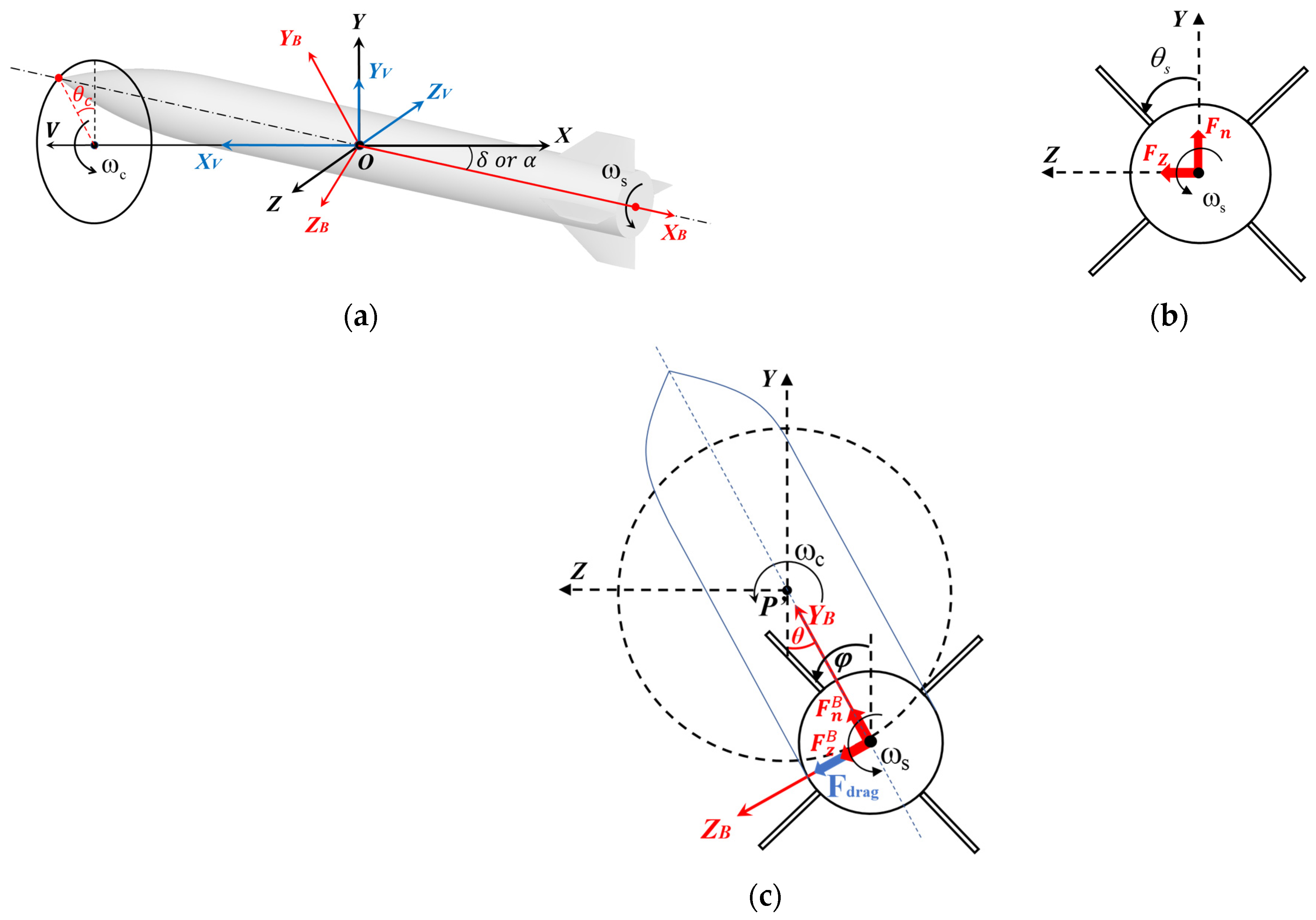
Figure 1. Definition of coordinate systems, motion modes, and aerodynamic forces. (a) Coordinate systems and motion modes. (b) Profile of aerodynamic forces for spinning motion. (c) Profile of aerodynamic forces for spinning–coning coupled motion.
Aerospace 12 00225 g001
Figure 2. Configuration and dimension of AFF.
Aerospace 12 00225 g002
Figure 3. Computational domain and grid. (a) Partition of computational domain. (b) Overall computational grid (The green and yellow spheres represent interface 1 and 2, respectively). (c) Surface and profile grid (The blue part represents the projectile body and the red parts represent projectile fins. The fin on the leeward side is Fin1).
Aerospace 12 00225 g003
Figure 4. Transient aerodynamic coefficients in spinning–coning coupled motion at different time steps. (a) Lateral force. (b) Yawing moment.
Aerospace 12 00225 g004
Figure 5. Time-averaged aerodynamic coefficients for spinning AFF at Ma = 2.5 and ω ¯ = 0.05 . (a) Lateral force. (b) Yawing moment.
Aerospace 12 00225 g005
Figure 6. Aerodynamic coefficients related to pitch damping oscillation. (a) Transient pitching moment. (b) Pitch damping coefficients.
Aerospace 12 00225 g006
Figure 7. Aerodynamic coefficients for a 10° half-angle cone experiencing lunar coning motion at Ma = 2.0, ω ¯ c = 0.024 , and ω ¯ s = 0 .(a) Lateral force coefficient. (b) Yawing moment coefficient [32,33].
Aerospace 12 00225 g007
Figure 8. Transient total lateral force coefficients at AoAs. (a) Spinning motion. (b) Spinning–coning coupled motion.
Aerospace 12 00225 g008
Figure 9. Time-averaged total aerodynamic coefficients at AoAs. (a) Normal force coefficient. (b) Pitching moment coefficient. (c) Lateral force coefficient. (d) Yawing moment coefficient.
Aerospace 12 00225 g009
Figure 10. Time-averaged component coefficients at AoAs. (a) Body lateral force. (b) Fin 1 lateral force.
Aerospace 12 00225 g010
Figure 11. Transient total coefficients at α = 12.6 ° in a coning period. (a) Lateral force coefficient. (b) Yawing moment coefficient.
Aerospace 12 00225 g011
Figure 12. Time-averaged total coefficients at different non-dimensional spin rates. (a) Lateral force coefficient. (b) Yawing moment coefficient.
Aerospace 12 00225 g012
Figure 13. Time-averaged total coefficients at different non-dimensional cone rates. (a) Lateral force coefficient. (b) Yawing moment coefficient.
Aerospace 12 00225 g013
Figure 14. Time-averaged distributed lateral force coefficients along projectile longitudinal axis in the quasi-body-fixed coordinate system. (a) Projectile total lateral force. (b) Projectile body lateral force.
Aerospace 12 00225 g014
Figure 15. Pressure difference between the right- and left-side bodies about the AoA plane at x/L = 0.7. (a) Spinning motion. (b) Spinning–coning coupled motion.
Aerospace 12 00225 g015
Figure 16. Pressure contours and crossflow streamlines at x/L = 0.7 in the quasi-body-fixed coordinate system. (a) Spinning motion, α = 4.0 ° (left), α = 12.6 ° (middle), and α = 20.2 ° (right). (b) Spinning–coning coupled motion, α = 4.0 ° (left), α = 12.6 ° (middle), and α = 20.2 ° (right).
Aerospace 12 00225 g016aAerospace 12 00225 g016b
Figure 17. The contribution of coning motion to Fin 1 lateral force.
Aerospace 12 00225 g017
Figure 18. Pressure contours and crossflow streamlines at x/L = 0.962 and θs = 0° in the quasi-body-fixed coordinate system. (a) Spinning motion, α = 4.0° (left), α = 12.6° (middle), and α = 20.2° (right). (b) Spinning–coning coupled motion, α = 4.0° (left), α = 12.6° (middle), and α = 20.2° (right).
Aerospace 12 00225 g018
Figure 19. C m y and its fitting plane of spinning–coning coupled projectile at α = 4 ° . (The black dots and lines represent the calculated C m y in the above sections. The colored plane is the fitting plane obtained using C m y and crosses zero point when ω ¯ s = ω ¯ c = 0 ).
Aerospace 12 00225 g019
Figure 20. Response of complex AoA using different methods. (a) Spinning aerodynamic with angular motion theory. (b) Coupled aerodynamic with modified angular motion theory. (c) Coupled 3-DoF CFD-RBD calculation.
Aerospace 12 00225 g020
Figure 21. Response of complex AoA using revised angular motion theory after t = 6 s.
Aerospace 12 00225 g021
Table 1. Parameters of computational grid.
Mesh AMesh BMesh C
Axial (body)200340470
Spanwise365676
Circumferential120196276
Total (mil.)5.1211.2725.81
Table 2. Detailed computational conditions.
α   or   δ ω ¯ c : ω ¯ s
Effect of α or δ 4 ° , 8 ° , 12.6 ° , 20.2 ° , 30.3 ° ω ¯ c : ω ¯ s = 1 : 6
Effect of ω ¯ s 4 ° , 12.6 ° ω ¯ c : ω ¯ s = 1 : 0 ,   1 : 1 ,   1 : 3 ,   1 : 6
Effect of ω ¯ c 4 ° , 12.6 ° ω ¯ c : ω ¯ s = 0 : 6 ,   1 : 12 ,   1 : 6 ,   1 : 3
Table 3. Computation conditions for independence studies.
α   or   δ ω ¯ c : ω ¯ s Mesh TypeTime Step
Grid independence 20.2 ° ω ¯ c : ω ¯ s = 1 : 6 Mesh A
Mesh B
Mesh C
T 2 = 1 × 10 5     s
Time-step independence 12.6 ° ω ¯ c : ω ¯   s = 1 : 6 Mesh B T 1 = 4 × 10 6   s
T 2 = 1 × 10 5   s
T 3 = 2.5 × 10 5   s
Table 4. Time-averaged aerodynamic coefficients and their relative differences among three meshes.
CnCzCmzCmy
Mesh A3.70050.00172.1591−0.3361
Mesh B3.68450.00182.1685−0.3263
Mesh C3.63130.001852.1819−0.3143
(Mesh A-Mesh B)/Mesh A0.43%−5.88%−0.44%2.92%
(Mesh A-Mesh C)/Mesh A1.87%−8.82%−1.06%6.49%
(Mesh B-Mesh C)/Mesh B1.44%−2.78%−0.62%3.68%
Table 5. Structural and aerodynamic parameters at α = 4 ° .
Structural ParameterValuesAerodynamic ParameterSpinning MotionSpinning–Coning Coupled Motion
L (m)0.4572 C D 0.4150.394
m (kg)2.48 C L α 5.8215.878
I x (kg∙m2)0.001 C m z α −0.326−0.339
I y (kg∙m2)0.354 C m y α , ω ¯ s −0.527−0.527
ρ (kg∙m3)3700 C m y α , ω ¯ c -−14.902
X ¯ c g 0.5 C m q + C m α ˙ −1.301−1.301
Disclaimer/Publisher’s Note: The statements, opinions and data contained in all publications are solely those of the individual author(s) and contributor(s) and not of MDPI and/or the editor(s). MDPI and/or the editor(s) disclaim responsibility for any injury to people or property resulting from any ideas, methods, instructions or products referred to in the content.