Abstract
Differing from traditional isobaric combustion, a pulse detonation-based ramjet (PD-Ramjet) was proposed in this study to enhance the efficiency of traditional ramjets. By using a two-dimensional numerical simulation method, the filling process and detonation initiation process of the hydrogen/air stoichiometric mixture in channels equipped with typical flameholders were studied under the inflow condition of a ramjet combustor, and the influences of the typical flameholders on the filling process and detonation initiation process were analyzed. Single cavity, sudden expansion cavity, central cavity, and V-shaped groove were chosen as typical ramjet flameholders. The simulation and analysis results indicated that the flameholders would affect the filling effect, and the blocking ratio had a great influence on the filling process. The hydrogen volume discharged from the outlet of the channel and the time for mixed gas to reach the outlet were related to the blocking ratio and the cavity aft wall inclination angle. The detonation initiation process revealed that the flameholders promoted the generation of detonation waves. Contrastingly, the detonation wave could not be initiated in the channel without flameholders despite the better filling effect. Moreover, different flameholders would change the position of high-pressure point formation and the time for generating the stable detonation wave. On the whole, the sudden expansion cavity had a lower blockage ratio and also gave consideration to the filling effect and detonation initiation characteristic, making it the most suitable flameholder structure for PD-Ramjet in this study.
Keywords:
detonation; detonation initiation process; ramjet; flameholders; numerical study; CFD; hydrogen; combustion 1. Introduction
The ramjet, a type of jet engine with a relatively simple structure, is capable of generating substantial thrust and is suitable for high-speed, high-altitude flight. However, in order to make the ramjet work normally, a booster device, such as a rocket engine, is typically necessary to provide the power needed for starting, which means that it cannot operate under static conditions. The Pulse Detonation Engine (PDE) is a new type of propulsion system that offers several potential advantages over conventional propulsion systems like gas turbine engines, including higher thermodynamic efficiency [1,2,3], lower specific fuel consumption [4,5,6], and reduced overall weight and cost [7]. Furthermore, within the range of 0 to 5 Ma, the performance of PDE surpasses that of ramjets [8]. Therefore, this paper proposes a pulse detonation-based ramjet (PD-Ramjet) as a replacement for traditional isobaric combustion. The PD-Ramjet not only broadens the flight envelope but also achieves a self-pressurization effect, resulting in improved thermodynamic cycle efficiency and overall performance of conventional ramjets.
In recent years, significant progress has been made in the research on detonation engines, but how to rapidly and effectively form a stable detonation wave over a short distance remains one of the core challenges. Current research on the ignition of detonation waves is primarily focused on the deflagration-to-detonation transition (DDT), and various initiation methods have been developed, such as multipoint successive ignition [9,10], jet ignition [11,12,13,14,15,16], obstacles-induced initiation [17,18,19], and shock wave focusing ignition [20], etc. Sosikov et al. [21] carried out the experiment of multi-point detonation ignition in a circular arrangement and discussed the causes of complex cellular structure in the detonation initiation process and ways to eliminate them. Ishii et al. [22] conducted experimental studies to investigate the detonation initiation and DDT process of a hot jet under the inflow conditions of 0.9 and 1.2 Ma. Cai et al. [23] also performed experimental research on detonation initiation and the DDT process in supersonic flow using a hot jet and analyzed the complex wave structure in the detonation tube and the interaction between the wall and the shock wave. Sheng et al. [24] carried out a numerical simulation on the dynamic behavior of flame acceleration and DDT in a duct with different obstacle layouts in non-homogeneous concentration fields. Results showed that turbulent combustion and self-ignition effects were the main factors affecting flame acceleration. Ni et al. [25] carried out a numerical simulation of hydrogen–air flame acceleration and detonation initiation in tubes equipped with arc obstacles of different chord lengths. The results revealed that the optimal chord length was half the diameter, in which the detonation wave propagated at a high velocity while maintaining a small deflagration-to-detonation transition distance. Furthermore, three different regimes were found in the flame acceleration and detonation initiation for different chord lengths. Brunoro Ahumada et al. [26] experimentally researched the detonation initiation behind two solid obstructions with uneven blockage ratio and opening shape and confirmed the importance of the blockage ratio pattern for overpressure estimation during gaseous explosions. Habicht et al. [27] conducted experimental investigations on detonation initiation through shock focusing at elevated pressure conditions in a pulse detonation combustor. The results indicated that the initial static pressure increase reduced the critical shock strength required for successful detonation initiation by means of a focusing shock wave. To refine the reflector design for higher detonation initiation reliability, Yang et al. [28] carried out a numerical simulation on detonation onset due to the energy accumulation effect and compared the energy accumulation abilities of seven different reflectors. Nikitin et al. [29] numerically investigated the evolution of the cellular structure of detonation waves under the condition of non-uniform initiation in a stoichiometric mixture of hydrogen with air and analyzed the dependence of cellular structure on the heterogeneity of initiation sources and chemical kinetic mechanism. Chen et al. [30] carried out a numerical simulation on the behaviors of detonations in a non-homogeneous medium. Results showed that characteristics of detonations in a non-uniform medium were controlled by the coupling role of gradient and confinement. Dai et al. [31] carried out a numerical simulation on Detonation Initiation and Propagation with a Symmetric-Jet in Supersonic Combustible Gas. The results verified that the appropriate jet strength when using a symmetric-jet resulted in a more desirable ignition velocity and a shorter distance to achieve detonation. Yarkov et al. [32] numerically researched the effect of channel geometry on the flame acceleration and transition to detonation in acetylene–oxygen–nitrogen mixtures and found that the peculiarities of the compression and rarefaction wave evolution were responsible for a difference between the flame dynamics in channels of different geometry. Liu et al. [33] numerically researched the propagation characteristics of the detonation wave in the bifurcated tube with various angles and analyzed the diffraction and reflection phenomena of detonation waves passing through bifurcation tubes. Zhao et al. [34] conducted numerical simulations to investigate the flame acceleration and DDT process in a narrow rough channel and explored the formation mechanism of galloping detonation in the rough channel. Jiang et al. [35] carried out a numerical simulation on detonation re-initiation through multiple reflections in a bifurcated channel filled with an n-heptane/air mixture and analyzed the effects of droplet diameters on re-initiation and the interaction between shock waves and droplets. The results showed that compared with the detonation propagating in a pure gaseous mixture, detonation was easier to decouple in two-phase mixtures during the diffraction stage due to the droplet fragmentation and evaporation process, and lots of unburned fuels were left behind the detonation wave. Kim et al. [36] conducted experimental research on the ignition and combustion characteristics of a tandem cavity-based scramjet combustor with side-by-side identical cavities, and a micro pulse detonation engine was utilized for ignition. Tunik et al. [37] investigated the energy efficiency of a supersonic ramjet engine with detonation combustion of a hydrogen–air mixture in an axisymmetric Laval nozzle. This axisymmetric Laval nozzle could provide steady-state detonation combustion of a stoichiometric hydrogen–air mixture at an altitude of about 40 km and with freestream Mach numbers 9 and 12. Cai et al. [38] investigated detonation combustion initiated with a hot jet in supersonic H2–O2–air mixtures by large-scale 3D simulations. Results showed that more complex and irregular detonation fronts could be observed in the 3D case compared with the 2D detonation. The slapping wave reflections on the side walls in the 3D detonation resulted in the second oscillation along with the main one, which presented stronger instabilities compared with the 2D case. Crane et al. [39] conducted 3D detonation simulations solving the compressible Navier–Stokes equations with detailed chemistry in both square-channel and round-tube geometries. The results showed that 3D simulations in the square tube show highly regular blast latticing, smaller detonation cells, and highly oscillatory velocities when compared to the round-tube simulations. Round-tube simulations showed more spatially non-uniform blast dynamics. Mark et al. [40] conducted experiments in an obstructed narrow rectangular channel and revealed new details of the three-dimensional propagation behavior of supersonic combustion waves. The results showed that the fast-flame structure in the square channel was like that observed in the narrow channel, being on average planar across the channel width, with local flame corrugations generated as a result of Richtmyer–Meshkov instabilities.
For efficient ignition and flame stabilization, a recirculation zone is essential in a ramjet combustion channel, where the local flow velocity is lower than the propagation speed of the turbulent flame [41,42]. Flameholders are often configured in a ramjet combustion channel, such as a sudden expansion structure, cavity, strut, central cone, and V-shaped groove. Fureby et al. [43] represented a numerical study of flow, injection, mixing, self-ignition, and turbulent combustion in a dual-mode ramjet combustor with a cavity flameholder and reported two stabilization combustion modes in ramjet experiments. Morales et al. [44] experimentally investigated the premixed cavity stabilized flames in a high-speed ramjet engine under the influence of varying mean pressure gradients. The results demonstrated that the performance and stability of a ramjet cavity flame could be influenced by the mean pressure gradient. Mesallam et al. [45] experimentally investigated a diffusion jet flame consisting of a newly developed flameholder to simulate the ramjet effect. The flameholder was a double cone with three fuel ports on the top cone to improve the mixing of fuel and air. Zhang et al. [46] conducted experiments to investigate the ignition and lean blowout performance in the combustor with a pilot trapped-vortex cavity and a radial V-shaped flameholder.
So far, most studies on detonation initiation have been conducted under static conditions, with few considering actual inflow conditions and different-shaped detonation chambers. Notably, no research has proposed or investigated the effects of actual inflow conditions and different flameholder-equipped channels for PD-Ramjet. Therefore, this paper firstly conducted numerical research on the filling process and detonation ignition process in channels equipped with typical flameholders of ramjet in order to achieve the formation of detonation waves in the PD-Ramjet. Single cavity, sudden expansion cavity, central cavity, and V-shaped groove were chosen as typical flameholders. The obtained results were valuable and provided crucial references for both fundamental research and practical applications of PD-Ramjets.
2. Physical Models and Calculation Methods
2.1. Physical Models
In this paper, five different-shaped channels equipped with typical ramjet flameholders were selected as simulation models. The dimensions of the channel were set to a length of 400 mm and a height of 42 mm. To accurately simulate the filling process and match the configuration of an actual ramjet combustor, isolators with a length of 30 mm and a sudden expansion ratio of 0.75 were integrated in front of each channel. The physical models of the five cases are depicted in Figure 1. Case 1 was a normal channel without any flameholder. For Case 2, a single embedded cavity with the aft wall inclination angle of 45° was configured in the channel. In this paper, all the inclination angles of the aft wall were 45°. The dimensions of the cavity were set to a length of 35 mm and a depth of 6 mm. The blockage ratio was 0.28. For Case 3, a convex cavity with an aft wall inclination angle of 90° was configured in the channel. The length of the cavity was also 35 mm, whereas the depth was set to 10 mm. The blockage ratio was also 0.28. For Case 4, a cavity with a front central cone was configured in the channel based on Case 1. The depth of the central cavity was set to 10 mm, and the distance from the inlet of the channel to the left end of the central cavity was chosen as 20 mm. The blockage ratio was 0.47. For Case 5, a V-shaped groove was configured at the central axis of the channel. The dimensions of both the length and height of the V-shaped groove were set to 6 mm, while the distance from the inlet of the channel to the leading edge of the central cone was chosen as 20 mm. The blockage ratio was 0.14.
Figure 1.
The physical models of five channels equipped with typical ramjet flameholders. (a) Case 1; (b) Case 2; (c) Case 3; (d) Case 4; (e) Case 5.
2.2. Calculation Methods and Validation
2.2.1. Calculation Methods
The two-dimensional transient Reynolds-averaged Navier–Stokes equations (RANS) were solved in this study. The numerical simulation was carried out based on ANSYS Fluent 17.1 software. The chemical reaction mechanism adopted in this study was the 8-species and 19-step H2 mechanism proposed by Westbrook [47]. The standard k-ε turbulence model using the Eddy Dissipation Concept (EDC) was employed in all simulations, which was put forward by Magnussen in 1981. The effects of turbulence and detailed chemical reactions were considered in the reaction flow, and the reactions in the flow process were determined by the Arrhenius formula. This model had obvious advantages for the simulation of a detailed reaction mechanism, and the model constants were as follows: Cmu was 0.09, C1-Epsilon was 1.44, C2-Epsilon was 1.92, TKE Prandtl Number was 1, TDR Prandtl Number was 1.3, Energy Prandtl Number was 0.85, Wall Prandtl Number was 0.85, and Turb. Schmidt Number was 0.7. The second-order implicit scheme was used, and the solution method of Pressure Implicit with Splitting of Operators (PISO) was adopted due to the unsteady detonation process. This algorithm was put forward by Issa in 1986, and the widely used SIMPLE algorithm was modified by one step, which improved the convergence speed and had more obvious advantages in unsteady calculation. In the calculation, the second-order implicit scheme was used to discretize the time and space direction, respectively, and the fixed time step method was used for iterative calculation. The time step was 10−7 s. The adaptive mesh refinement method was applied to refine the local mesh in regions with significant temperature gradients. The small-scale fine grid was used to calculate the physical parameters with large range and drastic change, and the large-scale coarse grid was used to calculate the physical parameters with slow change, which saved the calculation cost and effectively improved the calculation accuracy. The refined grids of numerical simulation all utilized adaptive grids with refinement level 3, that is, grids of 0.25 mm, 0.125 mm, and 0.0625 mm. The gas was assumed to be an ideal gas [2,12,18,48], and a stoichiometric mixture of hydrogen/air was used as the combustible mixture. The inlet parameters of the channel were determined based on the inlet parameters of the ramjet combustor at a flight altitude of 18 km and a flight Mach number of 3. The initial pressure and temperature of the stoichiometric mixture were set to 0.17 MPa and 582 K, respectively. During the filling process, the inlet of the channel was opened as a velocity inlet, and the inflow velocity of the stoichiometric mixture was 0.3 Ma. After the filling process, the inlet of the channel was closed as a thrust wall, and a high-temperature ignition zone was arranged close to the inlet. Figure 2 shows the ignition zone and diagram of adaptive mesh refinement changes with temperature.
Figure 2.
Ignition zone and diagram of adaptive mesh refinement changes with temperature.
The combustion process involves interactions between different components and turbulent states. The governing equations for mass, momentum, energy, species, and turbulent transport were
Here, was the density of the mixture, was the velocity vector, was the pressure, and was the viscous stress, which could be expressed as
In which was the dynamic viscosity of the mixture, was the unit tensor, was the temperature, was the mass fraction of reactant, was the reaction rate, was the total release energy of chemical reaction, and represented thermal conduction coefficient and mass diffusion coefficient, respectively, was the universal gas constant, and was the molecular weight. was the energy density, which was related to the enthalpy H by
Here, H was defined by
The finite rate model was utilized to simulate fuel combustion reactions, utilizing the global reaction mechanism of H2/air. The reaction rate could be derived from the Arrhenius rate law, as outlined below:
where denoted the -th species, A was the pre-exponential factor, was the mass fraction, T was the temperature, was the temperature exponent, was the activation energy of reactions, and R was the universal gas constant.
2.2.2. Validation
To verify the reliability of the simulation results, comparisons were made between the simulation results and the experimental results of the available documents and the Chapman–Jouguet (C-J) gaseous detonation wave parameters. The detonation pressure, detonation temperature, and detonation wave velocity were all compared. Furthermore, the validation of grid independence in this study referred to the published reference [48,49]. Figure 3 shows the pressure distribution at the same monitoring point under different grid sizes. It can be seen from the figure that the pressure change trend at the monitoring point was basically the same under different grid sizes. The calculation results of the grid size of 0.8 mm were obviously different from those of 0.5 mm, but the pressure curves of 0.1 mm and 0.5 mm were basically consistent. Considering the significantly higher computational expense and time required for the 0.1 mm grid and the lower accuracy for the grid of 0.8 mm, a grid size of 0.5 mm was selected for this paper to investigate the filling and detonation initiation characteristics in a PD-Ramjet.
Figure 3.
The pressure distribution results of the same monitoring points under different grid sizes.
Table 1 shows the comparison between the simulation results and the C-J detonation wave parameters calculated by the Chemical Equilibrium with Applications (CEA). On the whole, there was little difference between detonation temperature and detonation pressure, while the detonation velocity of Case 4 was higher than that of the other Cases, which was related to the blocking ratio. The detonation wave velocity in the simulation results was the average velocity measured after the detonation wave stabilized. The simulated pressure was the wave surface maximum value, known as the von Neumann peak value [48]. For this reason, the detonation pressure calculated by numerical simulation surpassed the C-J values calculated by CEA.

Table 1.
Comparison between the simulation results and C-J parameters by CEA.
Gaby et al. [50] carried out an experimental study on the flame acceleration process in an obstructed narrow rectangular channel, and the schlieren image is shown in Figure 4a. The figure clearly shows the development process of flame, vortex, and shock wave among obstacles, and it also shows the complex interaction process between shock waves and between shock waves and flame. Figure 4b showed the flame acceleration process in the narrow rectangular channel calculated by the above calculation method. It could be clearly observed that the flame front, vortex, and shock wave structures were highly similar to the experimental results, and the accelerated evolution process of the flame could be clearly captured. Therefore, the numerical simulation method used in this paper was accurate and reliable.
Figure 4.
The experimental schlieren image and the density gradient contours calculated by the above calculation method. (a) Experimental schlieren image; (b) Numerical density gradient contours.
3. Results and Analysis
3.1. Filling Process in Channels with Typical Ramjet Flameholders
Figure 5 depicts the contours of hydrogen mass fraction during the filling process in Case 1 at different times. The hydrogen mass fraction in the hydrogen/air stoichiometric mixture is 0.0283, and the range of hydrogen mass fraction shown in the figure varies from 0 to 0.03. The inflow velocity of the stoichiometric mixture was 0.3 Ma. At t = 0.37 ms, the front end of the mixed gas was introduced into the channel. Due to the relatively high inflow velocity, the mixed gas propagated forward, resulting in low hydrogen concentrations on both sides of the channel near the inlet. At t = 0.76 ms, the front end of the mixed gas diffused to both sides of the channel, reaching a position of 20 mm. With the continuous filling of the mixed gas, the hydrogen concentration at both sides of the channel near the inlet gradually increased, and it was roughly equal to the mainstream at t = 5.17 ms. At t = 6.66 ms, the front end of the mixed gas reached the outlet of the channel, where the mixed gas was basically filled except for both sides of the channel near the outlet. This time was considered as the reference time in order to compare the filling effect in other channels with flameholders in this study.
Figure 5.
The contours of hydrogen mass fraction in the filling process in Case 1 at different times.
Figure 6 shows the contours of hydrogen mass fraction in the filling process in Case 2 at different times. At t = 0.37 ms, the front end of the mixed gas reached the channel. As the mixed gas propagated forward, it diffused into the cavity and then converged to the central axis and traveled through a sudden expansion section again. At t = 1.69 ms, a recirculation region was formed in the cavity, and the hydrogen concentration in the cavity was higher than that on both sides of the channel downstream of the cavity. As the mixed gas propagated forward, the hydrogen concentration distribution at the front region was discontinuous, which was caused by the cavity aft wall. At t = 6.43 ms, the front end of the mixed gas had reached the outlet of the channel, which was faster than Case 1. However, the filling effect was not as good as Case 1 at this time, and the hydrogen concentration at both sides of the channel near the outlet was roughly zero. As the filling process continued, some fresh mixed gas traveled out of the channel, causing some waste. At t = 6.66 ms, both sides of the channel near the outlet were basically filled with the mixed gas.
Figure 6.
The contours of hydrogen mass fraction in the filling process in Case 2 at different times.
Figure 7 illustrates the contours of hydrogen mass fraction in the filling process in Case 3 at different times. Compared with Case 2, the cavity was extended to the outside of the channel, and the aft wall inclination angle was 90°. Similarly, at t = 0.37 ms, the front end of the mixed gas was introduced into the channel. However, due to the different depth of the cavity and the inclination angle of the cavity aft wall, the subsequent filling process differed significantly from Case 2. The inclination angle of the cavity aft wall affected the concentration distribution in the front end of the mixed gas. When the cavity aft wall inclination angle was 45°, the high concentration region of the front end presented an arc shape. However, it was close to a sharp cone shape when the inclination angle was 90°. Compared with the contours of 2.73 ms in Case 2 and Case 3, the leading edge of mixed gas reached a position of 163 mm in Case 2. Whereas the propagation velocity of the front end in Case 3 was higher than that in Case 2 due to the sudden contraction of the flow path caused by the cavity aft wall, and the leading edge of mixed gas had reached a position of 178 mm in Case 3. As such, the hydrogen concentration of the front end was lower than that in Case 2, which could be clearly seen from Figure 6. Finally, at t = 6.66 ms, the hydrogen concentration in the cavity was basically the same as that in the mainstream, whereas the hydrogen concentration was low near the outlet of the channel.
Figure 7.
The contours of hydrogen mass fraction in the filling process in Case 3 at different times.
Figure 8 shows the contours of hydrogen mass fraction in the filling process in Case 4 at different times. As mentioned above, the central cavity caused a huge blockage. For this reason, after the mixed gas was introduced into the channel, the front end of the mixed gas was divided into upper and lower parts and diffused to both sides of the channel rapidly. At t = 0.82 ms, the filling effect in the central cavity was very poor, which can be clearly seen in the figure. With propagation downstream, two leading regions of the mixed gas converged to the central axis near the position of 100 mm, but the hydrogen concentration downstream of the central cavity was still very low. As the filling process continued, a wide range of low-concentration regions appeared at the front end of the mixed gas. At t = 5.94 ms, the front end of the low-concentration mixed gas roughly reached the outlet of the channel, and the central cavity was basically filled with the mixed gas evenly, in addition to the partial region near the cavity aft wall. At t = 6.66 ms, the hydrogen concentration was still low near the outlet of the channel.
Figure 8.
The contours of hydrogen mass fraction in the filling process in Case 4 at different times.
Figure 9 illustrates the contours of hydrogen mass fraction in the filling process in Case 5 at different times. At t = 0.37 ms, the mixed gas was introduced into the channel. After that, similar to Case 4, the front end of the mixed gas was divided into two parts and propagated forward, respectively. After it propagated through the V-shaped groove, two leading regions of the mixed gas converged to the central axis at t = 2.26 ms. As the filling process continued, the hydrogen concentration near the sudden expansion section was basically the same as that in the mainstream, while there was always a low-concentration region immediately in the V-shaped groove. At t = 6.66 ms, there was still no mixed gas filled on both sides of the channel near the outlet, and the hydrogen concentration in the V-shaped groove was still very low.
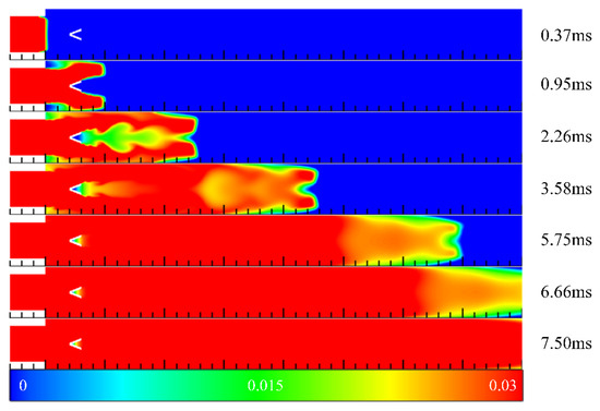
Figure 9.
The contours of hydrogen mass fraction in the filling process in Case 5 at different times.
3.2. Summary of Filling Process in Channels with Typical Ramjet Flameholders
Figure 10 depicts the hydrogen concentration at the 350 mm, 370 mm, and 400 mm sections in five channels at t = 6.66 ms, respectively. The hydrogen concentration distribution near the outlet of the channel is reflected by the figures directly. For Case 1, Case 2, and Case 5, the hydrogen concentration was high, and the filling effect was good in the middle section of the channel. However, the hydrogen concentration was low at both sides of the channel, and the concentration distribution near the outlet was uneven. For Case 3 and Case 4, the 90° inclination of the cavity aft wall disturbed the mixed gas to a certain extent during the filling process, resulting in more even hydrogen concentration near the outlet of the channel.
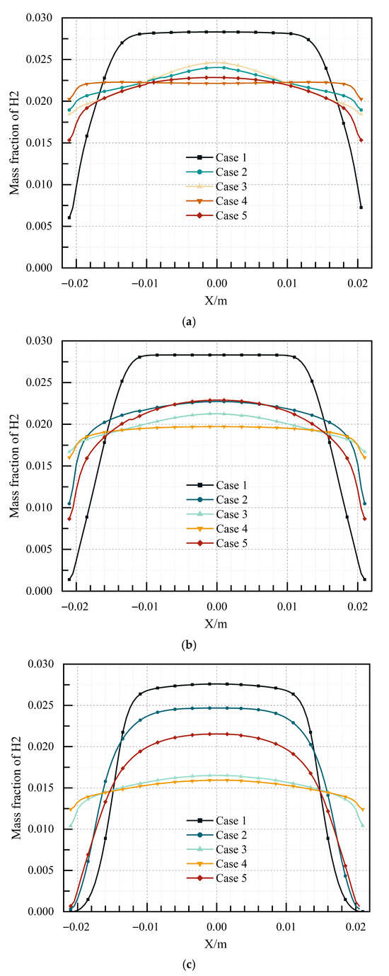
Figure 10.
The hydrogen concentration at the 350 mm, 370 mm, and 400 mm sections in five channels at t = 6.66 ms. (a) 350 mm section; (b) 370 mm section; (c) 400 mm section.
Figure 11 illustrates the average hydrogen concentration at the 400 mm section in five channels from 5.4 ms to 6.66 ms, which reflects the hydrogen discharged from the outlet of the channel at different times directly. Due to the huge blockage caused by the central cavity, hydrogen was first discharged from the outlet of the channel in Case 3, followed by Case 2 with the sudden expansion cavity. The last was Case 1 without any flameholder. As shown in the figure, the hydrogen concentrations of Case 3 and Case 4 were basically the same at t = 6.6 ms. It could be inferred that the hydrogen volume discharged from the outlet of the channel in Case 4 was more than that in Case 3. Similarly, the hydrogen volume discharged in Case 2 was more than that in Case 1. In terms of energy saving, the V-shaped groove was better than the single cavity, and the sudden expansion cavity was better than the central cavity. In addition, the blocking ratio in both Case 3 and Case 4 was 0.28. However, the time for mixed gas to reach the outlet of the channel in Case 3 was faster than that in Case 4. Hence, the time for mixed gas to reach the outlet was related to the cavity aft wall inclination angle, to a certain extent.
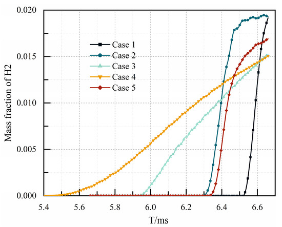
Figure 11.
The average hydrogen concentration at the 400 mm section in five channels at different times.
Table 2 lists the time for mixed gas to reach the outlet of the channel and the hydrogen volume discharged from the outlet during the filling process. As clearly shown in the table, the volume of hydrogen discharged from the outlet was related to the blocking ratio. The volume of hydrogen discharged from the outlet of the channel in Case 1 was the least, followed by Case 5 with a blocking ratio of 0.14, and the worst was Case 4 with a blocking ratio of 0.47. In addition, the blocking ratios were both 0.28 in Case 3 and Case 4, whereas the hydrogen volume discharged from the outlet in Case 3 was slightly more than that in Case 4. Similarly, the volume of hydrogen discharged from the outlet was also related to the cavity aft wall inclination angle. On the whole, the filling effect was quite different in five channels, and the flameholders would affect the filling effect greatly. The blocking ratio had a great influence on the filling process, and the blocking ratio should be minimized in the design for a better filling effect. The hydrogen volume discharged from the outlet and the time for mixed gas to reach the outlet during the filling process were related to the blocking ratio and the cavity aft wall inclination angle.
Table 2.
Relevant parameters of different cases in the filling process.
3.3. Detonation Initiation Process in Channels with Typical Ramjet Flameholders
After the filling process, the inlet of the channel was closed as a thrust wall, and a 30 mm × 2 mm rectangular high-temperature ignition zone was arranged close to the inlet. The initial pressure and temperature of the stoichiometric mixture in the ignition zone were set to 0.17 MPa and 3000 K, respectively. The ignition and detonation initiation processes in different channels were studied.
Figure 12 shows the contours of pressure in Case 1 at different times. The pressure waves rapidly propagated to both sides of the channel after ignition and were reflected. Since there were no obstacles in the channel to form a strong wall reflection, the compression wave propagated and diffused in an approximately unconfined space, and the pressure attenuated. Figure 13 illustrates the pressure and temperature distribution at the central axis in Case 1 at 240 μs and 250 μs, respectively. As shown in the figure, the flame front could not catch up with the pressure wave, and the pressure front and the temperature front had been decoupled at this time. The speed of the pressure wave was far lower than the C-J speed, and the detonation initiation failed.
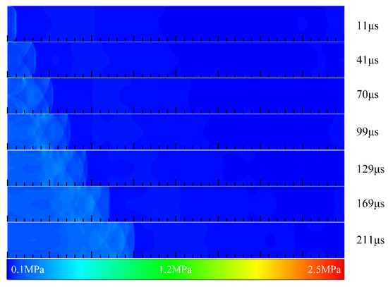
Figure 12.
The contours of pressure in Case 1 at different times.
Figure 13.
The pressure and temperature distribution at the central axis in Case 1 at 240 μs and 250 μs.
Figure 14 illustrates the contours of pressure in Case 2 at different times. The compression waves propagated to both sides of the cavity and aft wall at t = 58 μs and were reflected. These reflected waves converged and interacted in the cavity. With propagation through the contraction flow path caused by the cavity aft wall, the reflected wave pressure rose gradually. After propagating through the expansion section, the reflected wave quickly propagated forward and to the upper and lower sides of the channel. At t = 138 μs, the pressure rose sharply by the action of the wall reflection, and the reflected waves coalesced constantly near both sides of the channel. For this reason, two high-pressure regions were formed. After that, the high-pressure regions at both sides gradually converged to the central axis, and a plane detonation wave was initiated at the position of 146 mm at t = 190 μs, and the detonation wave was stable at t = 231 μs. Figure 15 shows the pressure and temperature distribution at the central axis in Case 2 at 240 μs and 250 μs, respectively. As shown in the figure, a detonation wave with a pressure of 2.1 MPa and a temperature of 2835 K was generated in the channel. Calculated from the figure, the detonation wave velocity was 1921 m/s.
Figure 14.
The contours of pressure in Case 2 at different times.
Figure 15.
The pressure and temperature distribution at the central axis in Case 2 at 240 μs and 250 μs.
Figure 16 illustrates the contours of pressure in Case 3 at different times. Since the cavity was extended to the outside of the channel, the time for the compression wave to reach the bottom of the cavity was longer than that of Case 2. At t = 63 μs, the compression wave reached the cavity aft wall. After that, a strong reflection occurred as a result of the inclination angle of 90°, and two high-pressure points were formed directly near the cavity aft wall at the position of 64 mm. The high-pressure points quickly developed into two high-pressure regions with propagation downstream, which coalesced to form a detonation wave surface with extremely strong pressure. At t = 137 μs, a plane detonation wave was initiated at the position of 127 mm, and the detonation wave was stable at 182 μs. Figure 17 shows the pressure and temperature distribution at the central axis in Case 3 at 240 μs and 250 μs, respectively. Manifested in the figure, a stable detonation wave was generated at this time. The pressure of the detonation wave was 2.2 MPa, and the temperature of the detonation wave was 2845 K. Calculated from the figure, the velocity of the detonation wave was 1976 m/s.
Figure 16.
The contours of pressure in Case 3 at different times.
Figure 17.
The pressure and temperature distribution at the central axis in Case 3 at 240 μs and 250 μs.
Figure 18 illustrates the contours of pressure in Case 4 at different times. As shown in the figure, the compression wave reached the conical surface at the front of the central cavity at t = 20 μs and was reflected. Owing to the configuration of the cavity structure at the center, the reflection intensity was significantly enhanced in the reduced flow channel. At t = 85 μs, two extremely high-pressure points were formed in the central cavity and developed into the high-pressure regions at both sides by the action of the wall. Subsequently, the two high-pressure regions converged and interacted. At t = 134 μs, a plane detonation wave was initiated at the position of 148 mm, and the detonation wave was stable at t = 185 μs. Figure 19 shows the pressure and temperature distribution at the central axis in Case 4 at 240 μs and 250 μs, respectively. As depicted in the figure, a detonation wave with a pressure of 2.2 MPa and a temperature of 2851 K was generated in the channel. Calculated from the figure, the detonation wave velocity was 1980 m/s.
Figure 18.
The contours of pressure in Case 4 at different times.
Figure 19.
The pressure and temperature distribution at the central axis in Case 4 at 240 μs and 250 μs.
Figure 20 illustrates the contours of pressure in Case 5 at different times. The compression waves at the front end reached the leading edge of the V-shaped groove at t = 32 μs and were reflected around. The reflected wave interacted with the transverse wave formed by the two side walls, and the pressure rose. After propagating through the V-shaped groove, the reflected waves and the transverse waves converged near the central axis, resulting in the formation of a high-pressure region. As they propagated forward, two high-pressure points were formed with a pressure of 0.85 MPa near both sides of the wall. However, the pressure of these high-pressure points was not as high as in the previous cases. As such, the pressure gradually advanced during the propagation process downstream, forming a high-pressure region. Finally, a plane detonation wave was generated at a position of 190 mm at t = 245 μs, and the detonation wave was stable at t = 301 μs. Figure 21 shows the pressure and temperature distribution at the central axis in Case 5 at different times. Manifested in the figure, the position of the wave front was about 182 mm at t = 240 μs. At this time, the detonation wave was not completely stable, and the pressure of the wave front was still in the decline stage. Subsequently, a stable detonation wave was generated at t = 320 μs. The pressure of the detonation wave was 2.2 MPa, and the temperature of the detonation wave was 2831 K. Calculated from the figure, the velocity of the detonation wave was 1927 m/s.
Figure 20.
The contours of pressure in Case 5 at different times.
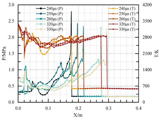
Figure 21.
The pressure and temperature distribution at the central axis in Case 5 at different times.
3.4. Summary of Detonation Initiation Process in Channels with Typical Ramjet Flameholders
Figure 22 reveals the pressure distribution at the central axis in the five channels at t = 240 μs. In addition to Case 1, stable and self-sustained detonation waves were generated in all other Cases. Although the filling effect was good in Case 1, the detonation wave could not be initiated without flameholders. The flameholders promoted the generation of a detonation wave. Moreover, different flameholders would change the time and position of high-pressure point formation, and the position of the high-pressure point formed by the sudden expansion cavity was the earliest. The detonation wave pressure in Case 4 with the central cavity structure was the largest, and the time for generating the stable detonation wave was the shortest, followed by Case 3 with the sudden expansion of the cavity, and Case 5 with a V-shaped groove was the longest. Essentially, there were both sections in the channels in Case 3 and Case 4, where the blocking ratio suddenly increased. The pressure rose sharply after the reflected wave passed through these sections, which promoted the generation of a high-pressure region. This explained the fast generation of the detonation wave in Case 3 and Case 4. For Case 5, as depicted above, the position of the wave front was about 182 mm at t = 240 μs, which was far less than the above cases, and the detonation wave was not completely stable at this time.
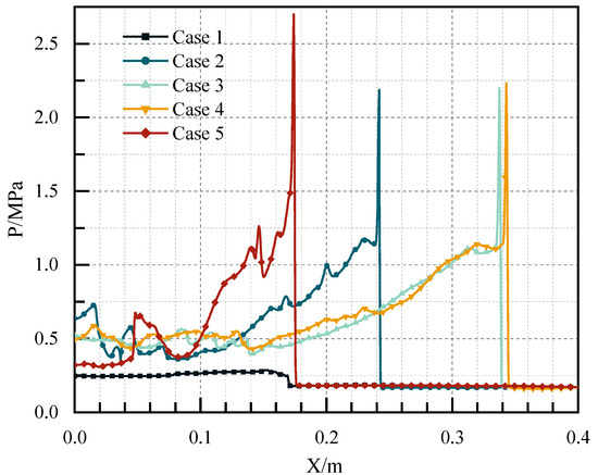
Figure 22.
The pressure distribution at the central axis in the five channels at t = 240 μs.
In general, the flameholders promoted the generation of a detonation wave, and the blockage ratio had an influence on the detonation parameters. The blockage ratio of Case 4 with the central cavity was very large, which was not conducive to the filling process and practical application. Not only that, but it also wasted fuel. In contrast, the blockage ratio of Case 3 with the sudden expansion cavity was smaller than that of the central cavity, the hydrogen concentration at the outlet was relatively even, and the detonation initiation characteristics were good. As such, the sudden expansion cavity was the most suitable flameholder structure for PD-Ramjet in this study. The effect of cavity aft wall inclination angle on the filling/detonation initiation process and structure optimization for a minimized blocking ratio will be studied further in the future.
4. Conclusions
In this study, a pulse detonation-based ramjet (PD-Ramjet), which is different from traditional isobaric combustion, was proposed to enhance the efficiency of traditional ramjets. The filling process and detonation initiation process of the hydrogen/air stoichiometric mixture in channels equipped with typical ramjet flameholders were studied under the inflow condition of a ramjet combustor, and the influences of the typical flameholders on the filling process and detonation initiation process were analyzed. The results were obtained as follows:
- (1)
- The flameholders would affect the filling effect greatly. The blocking ratio had a great influence on the filling process, and the blocking ratio should be minimized in the design for a better filling effect. The hydrogen volume discharged from the outlet of the channel and the time for hydrogen to reach the outlet of the channel were related to the blocking ratio and the cavity aft wall inclination angle during the filling process.
- (2)
- The initiation process showed that the flameholders promoted the generation of a detonation wave. In contrast, the detonation wave could not be initiated in the channel without the flameholders despite the better filling effect. Moreover, different flameholders would change the time and position of high-pressure point formation, and the position of the high-pressure point formed by the sudden expansion cavity was the earliest. The detonation wave pressure in the case with the central cavity was the largest, and the time for generating the stable detonation wave was the shortest, followed by the sudden expansion cavity, and the V-shaped groove was the longest.
- (3)
- On the whole, the blockage ratio of the central cavity was very large, which was not conducive to the filling process and practical application. Not only that, but it also wasted fuel. In contrast, the blockage ratio of the sudden expansion cavity was smaller than that of the central cavity, the hydrogen concentration at the outlet was relatively even, and the detonation initiation characteristics were good, which made it the most suitable flameholder structure for PD-Ramjet in this study.
Author Contributions
Conceptualization, L.W.; methodology, L.W.; software, Z.Z.; validation, W.Q.; formal analysis, L.W.; investigation, L.W.; resources, L.W.; data curation, L.W.; writing—original draft preparation, L.W.; writing—review and editing, L.W.; visualization, L.W.; supervision, Z.W.; project administration, Z.W.; funding acquisition, Z.W. All authors have read and agreed to the published version of the manuscript.
Funding
This research was funded by the National Natural Science Foundation of China, grant number 12372338; the National Natural Science Foundation of China, grant number 22205178; the Natural Science Foundation of Shaanxi Province of China, grant number 2022 JZ-20; the Guangdong Basic and Applied Basic Research Foundation, grant number 2023A1515011663; the Shenzhen Science and Technology Program, grant number JCYJ20230807145210021; and the Innovation Foundation for Doctor Dissertation of Northwestern Polytechnical University, grant number CX 2024013.
Data Availability Statement
The original contributions presented in this study are included in the article. Further inquiries can be directed to the corresponding author.
Conflicts of Interest
The authors declare no conflicts of interest.
Abbreviations
The following abbreviations are used in this manuscript:
| PDE | Pulse Detonation Engine |
| PD-Ramjet | Pulse Detonation-based Ramjet |
| DDT | Deflagration to detonation transition |
| C-J | Chapman–Jouguet |
| EDC | Eddy dissipation concept |
| PISO | Pressure implicit with splitting of operators |
| CEA | Chemical equilibrium and applications |
References
- Roy, G.D.; Frolov, S.M.; Borisov, A.A.; Netzer, D.W. Pulse Detonation Propulsion: Challenges, Current Status, and Future Perspective. Prog. Energy Combust. Sci. 2004, 30, 545–672. [Google Scholar] [CrossRef]
- Zhang, Z.; Wang, Z.; Wei, L.; Qin, W.; Zhao, X.; Xiao, J. Effects of Mixture Initial Conditions on Deflagration to Detonation Transition Enhanced by Transverse Jets. Energy 2024, 304, 132225. [Google Scholar] [CrossRef]
- Liu, J.; Wang, Z.; Zhang, Z.; Li, J.; Qin, W.; Huang, J. Reheat Effect on the Improvement in Efficiency of the Turbine Driven by Pulse Detonation. Def. Technol. 2024, 31, 200–210. [Google Scholar] [CrossRef]
- Zhang, Z.; Wang, Z.; Liu, J.; Qin, W.; Wei, L.; Yang, Y. Numerical Study on the Deflagration to Detonation Transition Promoted by Transverse Jet. Aerosp. Sci. Technol. 2023, 136, 108206. [Google Scholar] [CrossRef]
- Liu, J.; Wang, Z.; Qin, W.; Li, J.; Zhang, Z.; Huang, J. Effects of Detonation Initial Conditions on Performance of Pulse Detonation Chamber-Axial Turbine Combined System. Energy 2023, 278, 127765. [Google Scholar] [CrossRef]
- Wang, Z.; Yang, Y.; Huang, J.; Wang, Y.; Wei, L.; Qin, W. Numerical Study of Back-Propagation Suppression and Intake Loss in an Air-Breathing Pulse Detonation Engine. Aerosp. Sci. Technol. 2022, 126, 107566. [Google Scholar] [CrossRef]
- Wang, Z.; Wei, L.; Qin, W.; Liang, Z.; Zhang, K. Oxygen Concentration Distribution in a Pulse Detonation Engine with Nozzle–Ejector Combinational Structures. Proc. Inst. Mech. Eng. Part G J. Aerosp. Eng. 2021, 235, 2059–2068. [Google Scholar] [CrossRef]
- Yan, C.; Fan, W. Principle and Key Technology of Pulse Detonation Engine; Northwestern Polytechnical University Press: Xi’an, China, 2005. [Google Scholar]
- Frolov, S.M. Liquid-Fueled, Air-Breathing Pulse Detonation Engine Demonstrator: Operation Principles and Performance. J. Propuls. Power 2006, 22, 1162–1169. [Google Scholar] [CrossRef]
- Wang, Z.; Wei, L.; Li, H.; Pan, Z.; Huang, J.; Zhang, Y.; Liu, Z. Ignition Energy Effect on Detonation Initiation by Single and Two Successive Ignitions. Therm. Sci. 2020, 24, 4209–4220. [Google Scholar] [CrossRef]
- Brophy, C.M.; Netzer, D.; Forster, L.T.D. Detonation Studies of JP-10 with Oxygen and Air for Pulse Detonation Engine Development. In Proceedings of the 34th AIAA/ASME/SAE/ASEE Joint Propulsion Conference and Exhibit, Cleveland, OH, USA, 13–15 July 1998; American Institute of Aeronautics and Astronautics Inc., AIAA: Cleveland, OH, USA, 1998. [Google Scholar]
- Wang, Z.; Qin, W.; Huang, J.; Wei, L.; Yang, Y.; Wang, Y.; Zhang, Y. Numerical Investigation of the Effect of Jet Intensity from Internal Jet Tube on Detonation Initiation Characteristics. Int. J. Hydrogen Energy 2022, 47, 13732–13745. [Google Scholar] [CrossRef]
- Wang, Z.; Hui, Y.; Zhang, Y.; Xiao, J.; Qin, W.; Yang, Y. Numerical Study of Hydrogen Ratio Effect on Detonation Initiation Characteristics of Aviation Kerosene with Hydrogen Addition. Aerosp. Sci. Technol. 2024, 152, 109353. [Google Scholar] [CrossRef]
- Yu, J.; Tang, T.; Zhang, J.; Xiong, D.; Wang, H.; Sun, M. Analysis of influencing factors on numerical simulation of transverse jet in supersonic flow. Adv. Mech. Eng. 2023, 15, 16878132231214949. [Google Scholar] [CrossRef]
- Won, S.; Jeung, I.; Parent, B.; Choi, J. Numerical investigation of transverse hydrogen jet into supersonic crossflow using detached-eddy simulation. AIAA J. 2010, 48, 1047–1058. [Google Scholar] [CrossRef]
- Peterson, D.; Candler, G. Hybrid Reynolds-averaged and large-eddy simulation of normal injection into a supersonic crossflow. J. Propul. Power 2010, 26, 533–544. [Google Scholar] [CrossRef]
- Meyer, T.R.; Hoke, J.L.; Brown, M.S.; Gord, J.R.; Schauer, F.R. Experimental Study of Deflagration-to-Detonation Enhancement Techniques in a H2/Air Pulsed-Detonation Engine. In Proceedings of the 38th AIAA/ASME/SAE/ASEE Joint Propulsion Conference and Exhibit, Indianapolis, IN, USA, 7–10 July 2002; AIAA International: Indianapolis, IN, USA, 2002. [Google Scholar]
- Wei, L.; Wang, Z.; Qin, W.; Zhang, L. Numerical Study on Detonation Initiation Process in the Chamber with Characteristic Structures of the Dual-Mode Scramjet Combustor. Proc. Inst. Mech. Eng. Part G J. Aerosp. Eng. 2023, 237, 701–713. [Google Scholar] [CrossRef]
- Wang, Z.; Xiao, J.; Zhang, Y.; Long, H.; Zhang, Z.; Li, M.; Zhan, Y. Numerical Study on Detonation Initiation Process in a Reverse Ignition Boosted Detonation Chamber. Phys. Fluids 2024, 36, 105118. [Google Scholar] [CrossRef]
- He, L.; Rong, K.; Zeng, H.; Chen, X.; Zhang, Q.; Yu, P. Advances in Shock Wave Focusing and Induced. J. Propuls. Technol. 2015, 36, 1441–1458. [Google Scholar] [CrossRef]
- Sosikov, V.A.; Torunov, S.I.; Dudin, S.V. Smoothing the Front of the Detonation Wave in Experiments with Multipoint Initiation. In Proceedings of the 33rd International Conference on Equations of State for Matter, Elbrus, Kabardino-Balkaria, Russia, 1–6 March 2018; IOP Publishing Ltd.: Bristol, UK, 2019; Volume 1147, p. 012027. [Google Scholar]
- Ishii, K.; Akiyoshi, T.; Gonda, M.; Murayama, M. Effects of Flame Jet Configurations on Detonation Initiation. In Shock Waves, Proceedings of the 26th International Symposium on Shock Waves, Göttingen, Germany, 15–20 July 2009; Hannemann, K., Seiler, F., Eds.; Springer: Berlin/Heidelberg, Germany, 2009; pp. 239–244. [Google Scholar]
- Cai, X.; Chen, W.; Jin, K.; Deiterding, R.; Liang, J. An Experimental Study of Detonation Initiation in Supersonic Flow Using a Hot Jet. Combust. Flame 2023, 249, 112613. [Google Scholar] [CrossRef]
- Sheng, Z.; Yang, G.; Gao, W.; Li, S.; Shen, Q.; Sun, H. Modeling of Non-Homogeneous Premixed Hydrogen-Air Flame Acceleration and Deflagration to Detonation Transition in an Obstructed Channel. Int. J. Hydrogen Energy 2024, 50, 1209–1222. [Google Scholar] [CrossRef]
- Ni, J.; Pan, J.; Quaye, E.K.; Jiang, C. Numerical Simulation of Hydrogen-Air Flame Acceleration and Detonation Initiation in Tubes Equipped with Arc Obstacles of Different Chord Lengths. Acta Astronaut. 2020, 177, 192–201. [Google Scholar] [CrossRef]
- Brunoro Ahumada, C.; Mannan, M.S.; Wang, Q.; Petersen, E.L. Hydrogen Detonation Onset behind Two Obstructions with Unequal Blockage Ratio and Opening Geometry. Int. J. Hydrogen Energy 2022, 47, 31468–31480. [Google Scholar] [CrossRef]
- Habicht, F.E.; Yücel, F.C.; Gray, J.A.; Paschereit, C.O. Detonation Initiation by Shock Focusing at Elevated Pressure Conditions in a Pulse Detonation Combustor. Int. J. Spray Combust. Dyn. 2020, 12, 175682772092171. [Google Scholar] [CrossRef]
- Yang, Z.; Zhang, B.; Ng, H.D. Detonation Onset Due to the Energy Accumulation Effect of Shock Wave Focusing. Acta Astronaut. 2024, 215, 264–276. [Google Scholar] [CrossRef]
- Nikitin, V.F.; Mikhalchenko, E.V.; Stamov, L.I.; Tyurenkova, V.V.; Smirnov, N.N. Evolution of the Cellular Structure of Detonation Waves under the Condition of Non-Uniform Initiation. Acta Astronaut. 2023, 213, 156–167. [Google Scholar] [CrossRef]
- Chen, Q.; Huang, J.; Lei, G.; Wang, T.; Chen, J.; Han, W. Effects of Confinement on Detonation in H2–O2 Mixture with Transverse Concentration Gradient. Int. J. Hydrogen Energy 2023, 48, 18486–18497. [Google Scholar] [CrossRef]
- Dai, J.; Peng, L. Numerical Investigation on Detonation Initiation and Propagation with a Symmetric-Jet in Supersonic Combustible Gas. Aerospace 2022, 9, 501. [Google Scholar] [CrossRef]
- Yarkov, A.; Kiverin, A.; Yakovenko, I. Effect of Channel Geometry on the Flame Acceleration and Transition to Detonation in Acetylene-Oxygen-Nitrogen Mixtures. Acta Astronaut. 2024, 217, 273–279. [Google Scholar] [CrossRef]
- Liu, Y.; Pan, J.; Jiang, C.; Zhu, Y.; Li, J.; Quaye, E.K. Detonation Propagation Characteristics of H2/O2/AR in Multi-Angle Bifurcation Tubes. Int. J. Hydrogen Energy 2023, 48, 13248–13263. [Google Scholar] [CrossRef]
- Zhao, M.; Liu, D.; Li, M.; Xiao, H. Effect of Wall Roughness on Flame Acceleration and Deflagration-to-Detonation Transition in a Narrow Channel. Int. J. Hydrogen Energy 2024, 51, 880–893. [Google Scholar] [CrossRef]
- Jiang, C.; Pan, J.; Li, J.; Shi, X.; Quaye, E.K. Numerical Simulation of Detonation Re-Initiation in a 90° Bifurcated Channel Filled with n-Heptane/Air Mixture. Acta Astronaut. 2023, 202, 497–510. [Google Scholar] [CrossRef]
- Kim, M.; Koo, I.; Lee, K.; Lee, E.; Han, H.; Jeong, S.; Kim, H.; Choi, J. Experimental Study on the Ignition Characteristics of Scramjet Combustor with Tandem Cavities Using Micro-Pulse Detonation Engine. Aerospace 2023, 10, 706. [Google Scholar] [CrossRef]
- Tunik, Y.V.; Mayorov, V.O. Energy Efficiency of Detonation Combustion in Supersonic Ramjet Engines. Acta Astronaut. 2022, 194, 488–495. [Google Scholar] [CrossRef]
- Cai, X.; Liang, J.; Deiterding, R.; Che, Y.; Lin, Z. Adaptive mesh refinement based simulations of three-dimensional detonation combustion in supersonic combustible mixtures with a detailed reaction model. Int. J. Hydrogen Energy. 2016, 41, 3222–3239. [Google Scholar] [CrossRef][Green Version]
- Jackson, C.; Jonathan, T.; Xian, S.; Irenaeus, W.; Andreas, M.; Wang, H. Three-dimensional detonation structure and its response to confinement. Proc. Combust. Inst. 2023, 39, 2915–2923. [Google Scholar] [CrossRef]
- Kellenberger, M.; Ciccarelli, G. Three-dimensional behaviour of quasi-detonations. Combust. Flame 2020, 215, 145–156. [Google Scholar] [CrossRef]
- Nordin, K.; Fureby, C.; Karl, S.; Hannemann, K. Understanding scramjet combustion using LES of the HyShot II combustor. Proc. Combust. Inst. 2017, 36, 2893–2900. [Google Scholar] [CrossRef]
- Saghafian, A.; Terrapon, V.; Pitsch, H. An efficient flamelet-based combustion model for compressible flows. Combust. Flame 2015, 162, 652–667. [Google Scholar] [CrossRef]
- Fureby, C.; Nilsson, T. Large Eddy Simulation of Cavity Stabilized Ramjet Combustion. Aerosp. Sci. Technol. 2023, 141, 108503. [Google Scholar] [CrossRef]
- Morales, A.J.; Smerina, D.M.; Thornton, M.R.; Rising, C.J.; Sosa, J.; Johnson, R.F.; Kessler, D.A.; Goodwin, G.; Ahmed, K.A. Mean Pressure Gradient Effects on the Performance of Ramjet Cavity Stabilized Flames. Aerosp. Sci. Technol. 2023, 141, 108533. [Google Scholar] [CrossRef]
- Mesallam, I.M.; Attia, A.A.A.; El-Nagar, K.H.; Elsemary, I.M.M. Experimental Investigation on a Diffusion Jet Flame Performance Using a Developed Flame Holder Supplied with Air from a Concentric Pipe. Alex. Eng. J. 2023, 69, 561–570. [Google Scholar] [CrossRef]
- Zhang, Y.; He, X.; Wang, J.; Zhang, F.; Kang, Y. Ignition, Lean Blowout, and Flame Propagation in a Combustor Using Flameholder with a Trapped Vortex Cavity. Fuel 2022, 324, 124656. [Google Scholar] [CrossRef]
- Westbrook, C.K.; Dryer, F.L. Simplified Reaction Mechanisms for the Oxidation of Hydrocarbon Fuels in Flames. Combust. Sci. Technol. 1981, 27, 31–43. [Google Scholar] [CrossRef]
- Wang, Z.; Pan, Z.; Huang, J.; Wei, L.; Wang, Y.; Wang, Y. Effects of Double-Jet Positions on Detonation Initiation Characteristics. Aerosp. Sci. Technol. 2020, 97, 105609. [Google Scholar] [CrossRef]
- Hardeo, C.; Jessica, C.; Alexei, P.; Vadim, N.G.; Kareem, A.A. Chapman–Jouguet deflagration criteria and compressibility dynamics of turbulent fast flames for turbulence-induced deflagration-to-detonation transition. Phys. Fluids 2023, 35, 066122. [Google Scholar] [CrossRef]
- Ciccarelli, G.; Johansen, C.; Parravani, M. The role of shock–flame interactions on flame acceleration in an obstacle laden channel. Combust. Flame 2010, 157, 2125–2136. [Google Scholar] [CrossRef]
Disclaimer/Publisher’s Note: The statements, opinions and data contained in all publications are solely those of the individual author(s) and contributor(s) and not of MDPI and/or the editor(s). MDPI and/or the editor(s) disclaim responsibility for any injury to people or property resulting from any ideas, methods, instructions or products referred to in the content. |
© 2025 by the authors. Licensee MDPI, Basel, Switzerland. This article is an open access article distributed under the terms and conditions of the Creative Commons Attribution (CC BY) license (https://creativecommons.org/licenses/by/4.0/).