Article

Firing Test Campaign for a Hydrogen Peroxide Propulsion System for CubeSats in Vacuum Conditions

1
Department of Civil and Industrial Engineering, University of Pisa, 56126 Pisa, Italy
2
ESTEC—European Space Research and Technology Centre, Keplerlaan 1, 2201 AZ Noordwijk, The Netherlands
*
Author to whom correspondence should be addressed.
Aerospace 2025, 12(11), 1022; https://doi.org/10.3390/aerospace12111022
Submission received: 30 July 2025 / Revised: 7 November 2025 / Accepted: 11 November 2025 / Published: 18 November 2025
(This article belongs to the Section Astronautics & Space Science)

Abstract

This work reports the results of an on-ground experimental test campaign performed in the relevant environment (i.e., inside a vacuum chamber) of a blowdown H2O2 monopropellant propulsion system designed for CubeSat applications for the assessment of its propulsive performance and its thermomechanical behavior, both in continuous and pulse modes. The complete experimental characterization of the most important propulsive parameters of the engineering model of the propulsion system has been carried out with a suitably designed diagnostic equipment, consisting of a thrust balance capable of hosting an entire 3U CubeSat and all the relevant sensors. The propulsion system proved to match most of the requirements, both in pulse and continuous mode operations.

1. Introduction

The CubeSat’s market has seen a remarkable growth, which is expected to increase in the coming years thanks to the launch of many constellations. However, the more CubeSats that are launched into orbit, the greater the need to provide them with on-board propulsion systems; such systems will be crucial for satisfying the End-of-Life de-orbiting regulations [1] and to provide maneuvering capabilities for the collision avoidance [2]. Although it seems clear what the advantages of these systems are, it is not easy to understand how complex it is to design a propulsion system, especially one capable of satisfying their stringent mission requirements. Today, few nearly off-the-shelf European propulsion solutions can satisfy these requirements. In this context, the European Space Agency launched a call to identify the most promising European Propulsion Systems for CubeSats. The University of Pisa participated in this ESA call with the CHIPS project (CubeSat HTP Innovative Propulsion System), focused on designing, manufacturing, and testing an affordable chemical monopropellant propulsion system for CubeSats, which uses hydrogen peroxide as the propellant. Even if electric propulsion has always seemed the best candidate to consider when a low thrust is required [2], a chemical propulsion system allows one to reduce the total power consumption and generate a broader spectrum of thrust levels suitable for several CubeSats mission scenarios. On the other hand, the choice of HTP allows for a drastic reduction in health hazards and safety protection procedures while handling, compared to more toxic propellants [3]; moreover, the nominal performances of such a propellant, while used as a monopropellant, are just 20% less than hydrazine [4], but the volume-specific impulse achievable with 90% H2O2 is higher than for most other propellants due to its high density [5]. Hydrogen peroxide has the significant advantage that its decomposition temperature does not require the use of extremely expensive materials and manufacturing processes for the thrust chamber with respect to other high-energy green propellants, such as ammonium nitrate and hydrazinium nitroformate-based propellants ([6,7]). Previous experimental campaigns conducted in the laboratories of the University of Pisa were able to confirm all these favorable aspects of monopropellant propulsion systems using hydrogen peroxide at high concentrations and show their potential for applications where low thrust and tight control of the envelopes are required [8,9]. The hydrogen peroxide concentration chosen for CHIPS is 98% wt., also called HTP. The HTP is an unstable substance that tends to decompose if left in ambient conditions, or in contact with certain materials, with a decomposition rate proportionally increasing with the increase in the operating temperature, the hydrogen peroxide concentration, and the material contact surface area [10,11]. For this reason, the material selection represented an additional main requirement in the development of CHIPS, which was faced thanks to the expertise developed during previous projects [12]; this requirement added to other main design driving factors such as the simplicity, the low cost, and the reduced envelope, mass, and power consumption, which have greatly restricted the choice of components available on the market to realize the propulsion system.
The CHIPS project focuses on developing and testing an entire propulsion system occupying 3U of a CubeSat. The starting TRL for this activity was about 2. This low level allows for the use of COTS never tested in a space-related environment, and the build-up of an engineering model resembling the layout of the future flight model for the test campaign. The Agency gave the opportunity to test the propulsion system inside a vacuum chamber specifically modified for housing and sustaining small chemical propulsion system firings. This opportunity allows us to advance from previous experimental activities performed by the University of Pisa on the thruster and the catalyst of propulsion systems for small satellites [13,14,15,16] and to arrive at a higher TRL by testing critical components of the propulsion system in a relevant vacuum environment and by checking the potential of the COTS implemented inside the system.
Various pressure transducers and thermocouples inserted in the tested engineering model gave a complete overview of the status of the system during the tests, and a mass flow meter and a newly designed one-degree-of-freedom thrust balance capable of housing an entire 3U CubeSats while maintaining a reduced envelope to be integrated inside a small vacuum chamber directly recorded the mass flow rate and the generated thrust. The adopted solution of directly measuring the thrust of the propulsion system using a double pendulum horizontal thrust balance is not often adopted in the case of low thrust levels, as in the CHIPS case (<0.5 N). However, the designed configuration proved to be able to record very small thrust signals with an accuracy of 0.6% FS and easily interfaceable with different test facilities. The possibility of having a direct measure of both the mass flow rate and the thrust in a vacuum made the determination of the specific impulse of the system precise and reliable, allowing a truthful determination of the capabilities of this low-thrust monopropellant propulsion system fed by HTP. Finally, catalysts of different dimensions were inserted in the CHIPS catalytic bed and tested, and all of them were composed of P t / α A l 2 O 3 pellets. These pellets have been shown to have excellent thermomechanical resistance during previous test activities and be able to decompose 1 l of 98% hydrogen peroxide with very good efficiencies and minor surface degradation.
This study illustrates the CHIPS set-up and the results obtained in the experimental campaign conducted in vacuum conditions, showing its potential and feasibility to be employed as the main propulsion system in a CubeSat.

2. Propulsion System Design

Table 1 lists the main requirements imposed on the propulsion system developed in the frame of the CHIPS project. The requirements are mostly related to the class of mission achievable by the CubeSats and their limited mass, envelope, and power availability; these aspects are reflected in the definition of the main driving factors for the CHIPS design:
  • Maximization of the propulsive performance in terms of ∆v and total impulse capabilities;
  • Minimization of the dry mass;
  • Low cost;
  • Simplicity.
The driving factors pushed to make the system architecture as simple as possible using COTS products for the greatest part of the components, while making the best use of the resources available on CubeSats to obtain competitive performance and to guarantee the completion of most of the maneuvers required at this class of satellites.
Figure 1 shows a schematic of the proposed flight model propulsion system architecture:
  • A blowdown propellant management system contains both the propellant and a limited amount of pressurizing gas stored inside a 1U tank and separated by a bladder made of Viton, a material satisfying the HTP Grade I–II compatibility requirement. The tank shell is made of 316 stainless steels.
  • Two fill-and-drain valves, one for each fluid inside the tank, constitute the flight segment of the filling and draining system; a feed-line connects the tank side storing the propellant to the thrust chamber.
  • A filter and three solenoidal valves on this line guarantee the three barriers inhibit catastrophic events, as required in [17]. Valves, fittings, and tubes are all made of 316 stainless steels passivated to inhibit the HTP decomposition.
  • A monopropellant thruster composed of a catalytic bed and a nozzle generates the required thrust for moving the satellites.
Three sensors are also present in the system: one temperature sensor and one pressure transducer to monitor the status of the propellant inside the tank, and another temperature sensor to record the temperature reached by the thruster’s wall. All the materials of the listed components were selected to be compatible with the 98% wt. hydrogen peroxide used as the propellant. The choice of this propellant is a strong point of the propulsion system: the HTP is a non-toxic and low-cost propellant with long flight heritage. This propellant has a lower specific impulse at high concentration levels compared to the hydrazine and nitrate blend, but a high density offers performances comparable to those of the other two propellants. Furthermore, its ease of handling, the need for no pre-heater for the decomposition, and its relatively low decomposition temperature (900–1210 K), which allows avoiding the use of expensive materials for the combustion chamber, make hydrogen peroxide a promising, simple, and low-cost option for the CubeSats propulsion system.
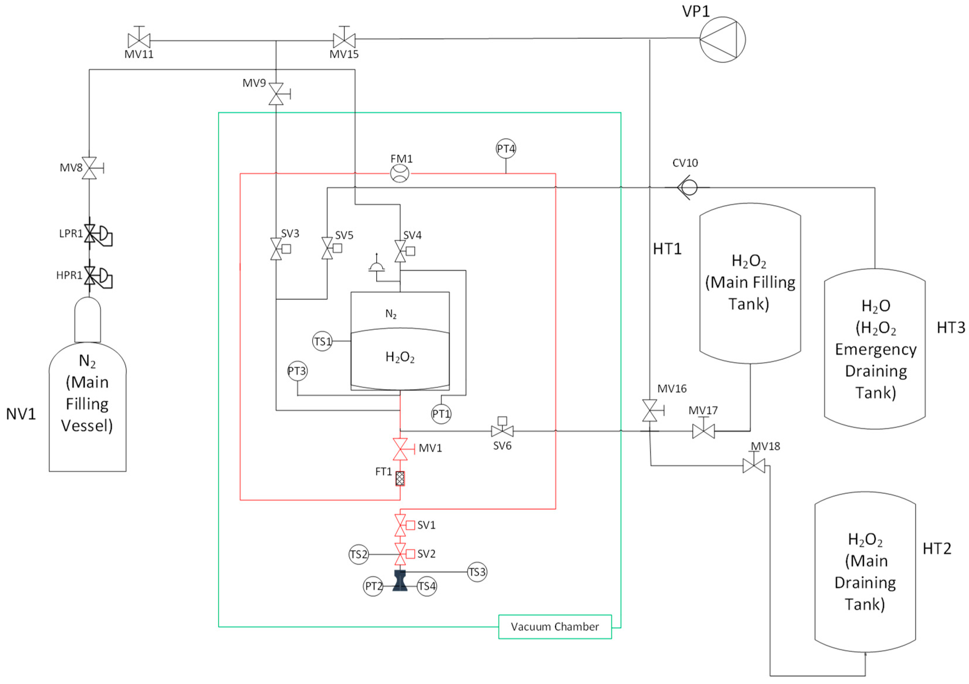
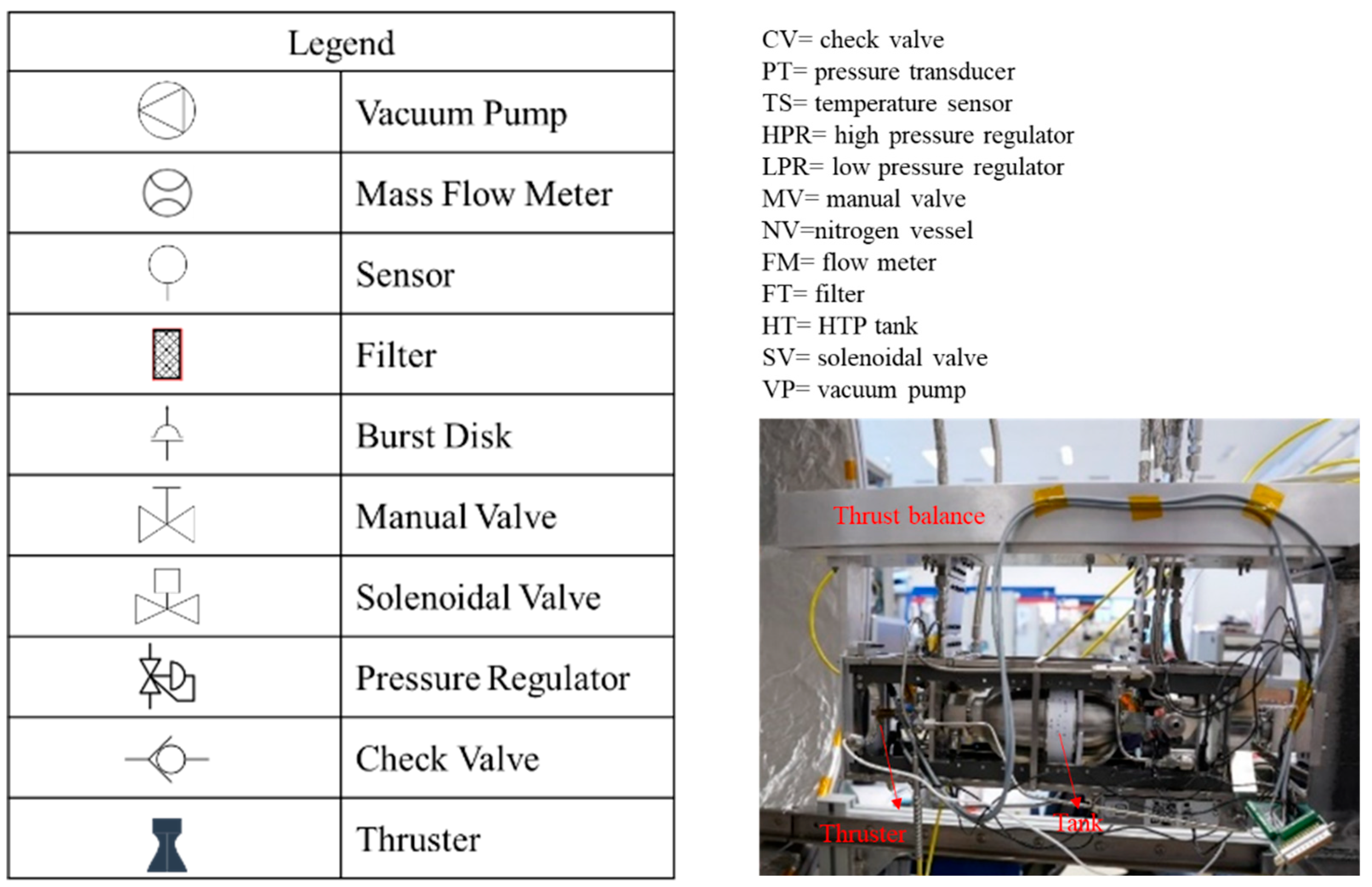
In the frame of the CHIPS project, two models of the same propulsion system were designed: the flight model (FM), described above, and the engineering model (EM). The main components are the same for both models: two fill and drain valves, one filter, one isolation valve, two solenoid valves, one thruster, one pressure transducer, and two temperature sensors. Obviously, the safety requirements imposed on the EM to be satisfied during the test campaign and the additional sensors for the full experimental characterization make the EM more complex than the FM. The thruster used in the EM test campaign is the same design for the FM and is developed by the University of Pisa. During the project, the lack of a COTS tank able to satisfy the imposed requirements forced us to design an innovative cuboidal tank with an envelope of 1U and a propellant storage capability up to 0.45 L. However, the EM made use of a COTS tank with a lower propellant capability and a greater envelope during the test campaign. Figure 2 shows the schematic of the engineering model and its actual realization. As shown, the feeding line (highlighted in red) has been kept as close as possible to that of the flight model in order to be able to test in the relevant environment some of the most critical components, such as firing valves and thrusters.

Thruster

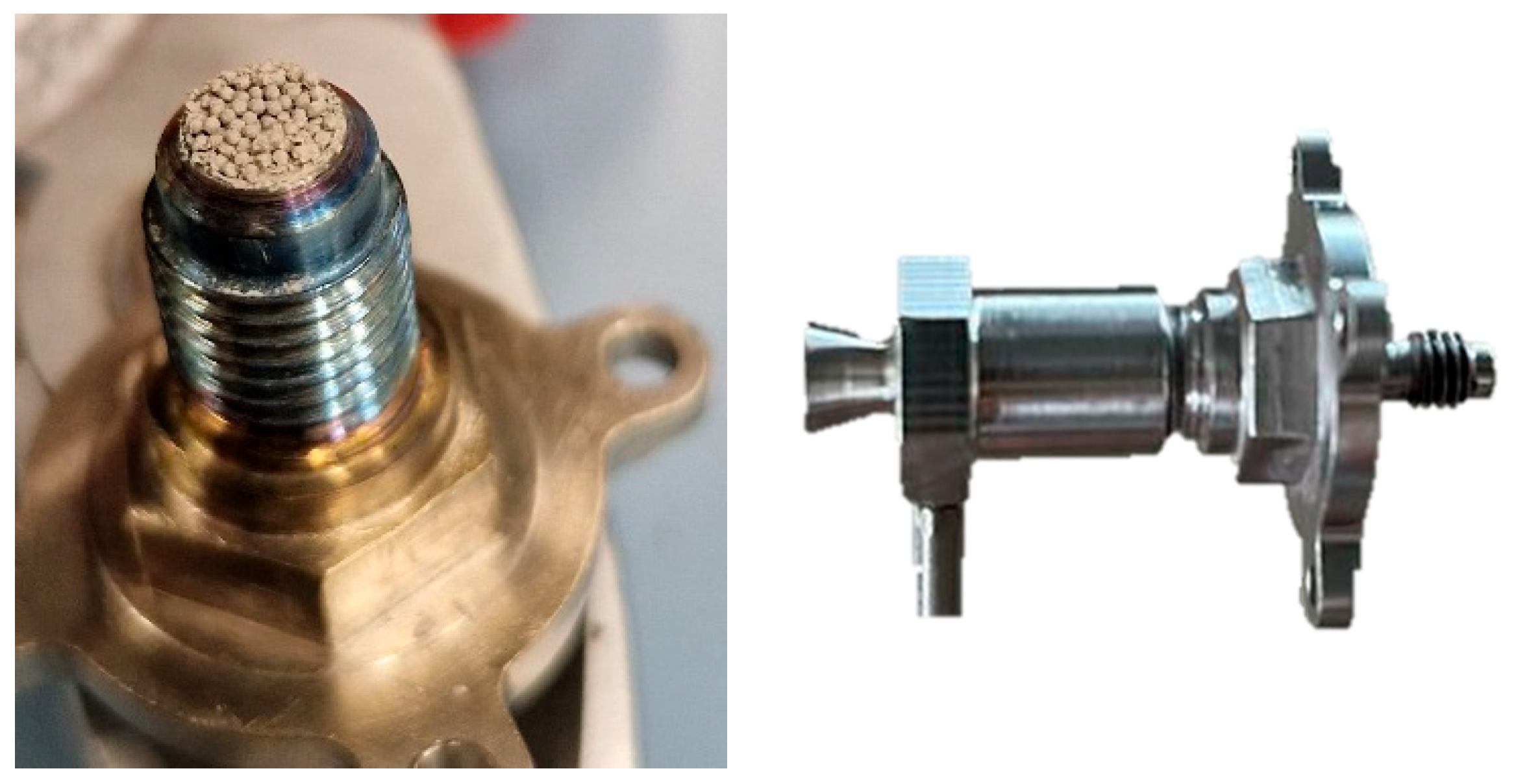
The thruster is the main component of the CHIPS, and it was entirely designed by the team of the University of Pisa, taking advantage of their great heritage in green propellant thrusters. Table 2 shows the requirements followed during the design process. The propulsion system designed is a monopropellant to meet the constraints of simplicity and minimum size; therefore, the thruster consists of a combustion chamber made of a catalytic bed where the propellant decomposes in a gas mixture accelerated through a nozzle. The operation in blowdown mode is another important feature of the system, which presents a feeding pressure decreasing from BOL to EOL. For this reason, the thruster design started by imposing the generation of the maximum thrust level (0.5 N) in the required range at the BOL conditions and the minimum required thrust level (0.125 N) at the EOL conditions. The other design choices based on the previous heritage were the use of a conical nozzle with an area ratio of 70 and a catalytic bed volume of about 226 mm3. The catalyst selected to fill the catalytic bed was Pt/α-Al2O3 pellets [18,19,20,21], which present a high resistance to thermal stress. The Chemistry Department of the University of Pisa accomplished the manufacturing of the catalyst. The sizing of the catalytic bed, the overall decomposition chamber, and the nozzle was based on the scaling down of the thruster developed during the PulCheR project [13,22]. A final component of the thruster assembly is the stand-off rods. These rods present a particular shape that allows them to detach the thruster from the tank and the other components of the propulsion system, reducing in this way the amount of heat coming from the thruster to the rest of the propulsion system. This is a critical aspect since the decomposition chamber reaches values close to 1000 °C during the operations, and if the generated heat reaches the tank or the feeding line, the HTP starts its self-sustained thermal decomposition, which onsets at temperatures of 100 °C. Figure 3 illustrates the pellet catalysts used and the thruster’s final assembly.

3. Test Apparatus

The developed engineering model represents the tested configuration. A 3U CubeSat structure houses the propulsion system and all the sensors, while four stainless steel lines depart from the drain, gas-filling, liquid-filling, and emergency-draining solenoidal valves of the system and enter inside the drain tank, the pressurant vessel, the main filling tank, and the emergency tank, respectively. The CubeSat structure is fixed to a one-degree-of-freedom thrust balance’s cradle, which is suspended by two flexures attached to the supporting structure. The flexures support the weight of both the cradle and the propulsion system, and they are extremely flexible in the axial direction in order to absorb a negligible amount of the axial thrust. The axial thrust is measured by a load cell aligned with the thrust vector and inserted in a flange adapter between the CubeSat structure and the thrust balance main body.
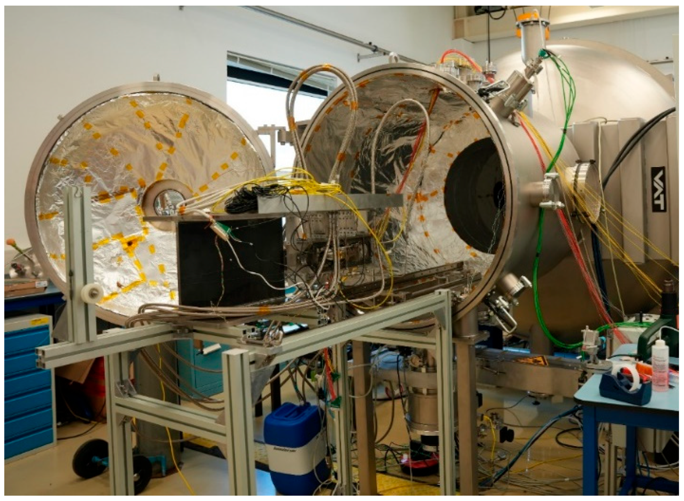
The facility selected to test the 0.5 N thruster is the Small Plasma Facility (SPF) at ESTEC, in the Netherlands. It consists of a vacuum chamber of 3.35 × Ø2 m main chamber with a 1 × Ø1 m hatch. These dimensions were suitable for inserting in the chamber the thrust balance housing the 3U CubeSat envelope containing the whole propulsion system mounted for testing (Figure 4). However, the space inside the vacuum chamber was not enough to insert the three tanks and the pressurant vessel connected to the four lines exiting from the EM. For this reason, these four containers were placed outside the chamber and connected to the lines inside the vacuum chamber by means of pass-through connections. Finally, the static calibration of the thrust balance, after its insertion inside the vacuum chamber, showed that it was able to measure the axial thrust with an accuracy of 0.6% FS, as reported in Table 3.

3.1. Diagnostic and Instrumentation

Table 4 reports the sensors used during the CHIPS experimental campaign with their range and accuracy values, and a reference to the position occupied inside the test segment. The accuracy of the sensors refers to a confidence level of 95.4% associated with plus or minus two standard deviations (±2σ).
The above-reported sensors included in the tested EM of CHIPS were fundamental for the full characterization of the propulsive performance of the system and the monitoring of the status of all the components. Two pressure transducers measured the pressure in the liquid and the gas side of the tank to monitor the feeding pressure and to check the absence of overpressure and the consequent pressure gradient across the bladder surface due to the HTP decomposition; the gas-side pressure transducer included a Pt-1000 thermoresistance to measure the pressurant nitrogen temperature. A J-type surface thermocouple recorded the liquid-side tank surface temperature to verify the margin with respect to the self-sustained decomposition temperature. Other two surface temperature sensors of type K monitored the firing valve and the catalytic bed surface status. A Coriolis mass flow meter placed on the feeding line gave the value of the mass flow rate coming to the thruster, and a pressure transducer placed downstream to this sensor allowed us to estimate the associated pressure losses and the corresponding feeding pressure inside the catalytic bed. A subminiature compression load cell, mounted on the balance cradle, measured the engine thrust. Finally, a pressure tap and a K-type thermocouple recorded the status of the combustion chamber gases. In particular, these sensors allow the measurement of the quantities reported in Table 5 with the corresponding accuracies. The accuracy of the various sensors reported in the table above was not sufficient to determine the accuracy with which estimating all the quantities of interest; in order to compute the accuracy of the measurements, the gravitational acceleration, the theoretical adiabatic decomposition temperature, the theoretical thrust coefficient, and the theoretical characteristic velocity were supposed to be known without uncertainty (or negligible with respect to the uncertainties of the other quantities):
g = 9.81 m s 2 ;
T a d (function of the H2O2 concentration);
c * ( t h e o ) = R T a d γ γ + 1 2 γ + 1 2 γ 1 (function of the H2O2 concentration);
C F ( t h e o ) = C F ( t h e o ) γ , A e A t h , p a m b (with expansion in vacuum p a m b 0   bar );
The uncertainty in the throat area is related to the manufacturing process of the nozzle and it is equal to:
2 σ A t h A t h = 4 % .
Starting from these assumptions, the determination of the accuracy of the quantities of interest obtained from the experimental results followed the process reported in the table below.
The National Instruments acquisition board gathered all the data coming from the sensors and transducers, and by a LabVIEW® data acquisition and control program, recorded and displaced real-time the values of these data. A “Red-Button” procedure implemented in the LabVIEW® code allows for the automatic closure of the firing valves and emptying of the tank through the emergency draining line in the case of the collected data surpassing a specific temperature or pressure threshold value imposed for guaranteeing the safety of the experiments. The sampling frequency was set to 2500 Hz. Two direct-current sources supplied different output voltages to the sensors and to the valves, respectively. This differentiation allowed for the application of a step-down voltage to the solenoidal normally closed firing valves during the firing of the thruster, from 12 Volts to 5 Volts, in order to reduce the valves’ self-heating and maintain their temperatures below the operating limit.

3.2. Vacuum Chamber

The SPF has been designed for testing electric thrusters, and in the nominal configuration it can achieve a minimal pressure of 10−7 mbar with a nominal pumping capacity of 128,000 L/s N2. It is equipped with a liquid nitrogen-cooled shroud, and the entire system is controlled by dedicated software. The chamber also presents a number of access flanges sufficient to insert in its internal volume all the sensors required during the CHIPS test campaign. The internal walls of the chamber were covered with a protective material to avoid any damage caused by a possible spillage of hydrogen peroxide on the chamber itself. All the materials composing the chamber are compatible and do not suffer corrosion by the gases generated by the decomposition of HTP; also, the graphite present inside the chamber is compatible with the environment generated by the exhaust gases inside the chamber. The main characteristics of the vacuum chamber are reported in Table 6 highlighting the differences between the electrical and the chemical setups.
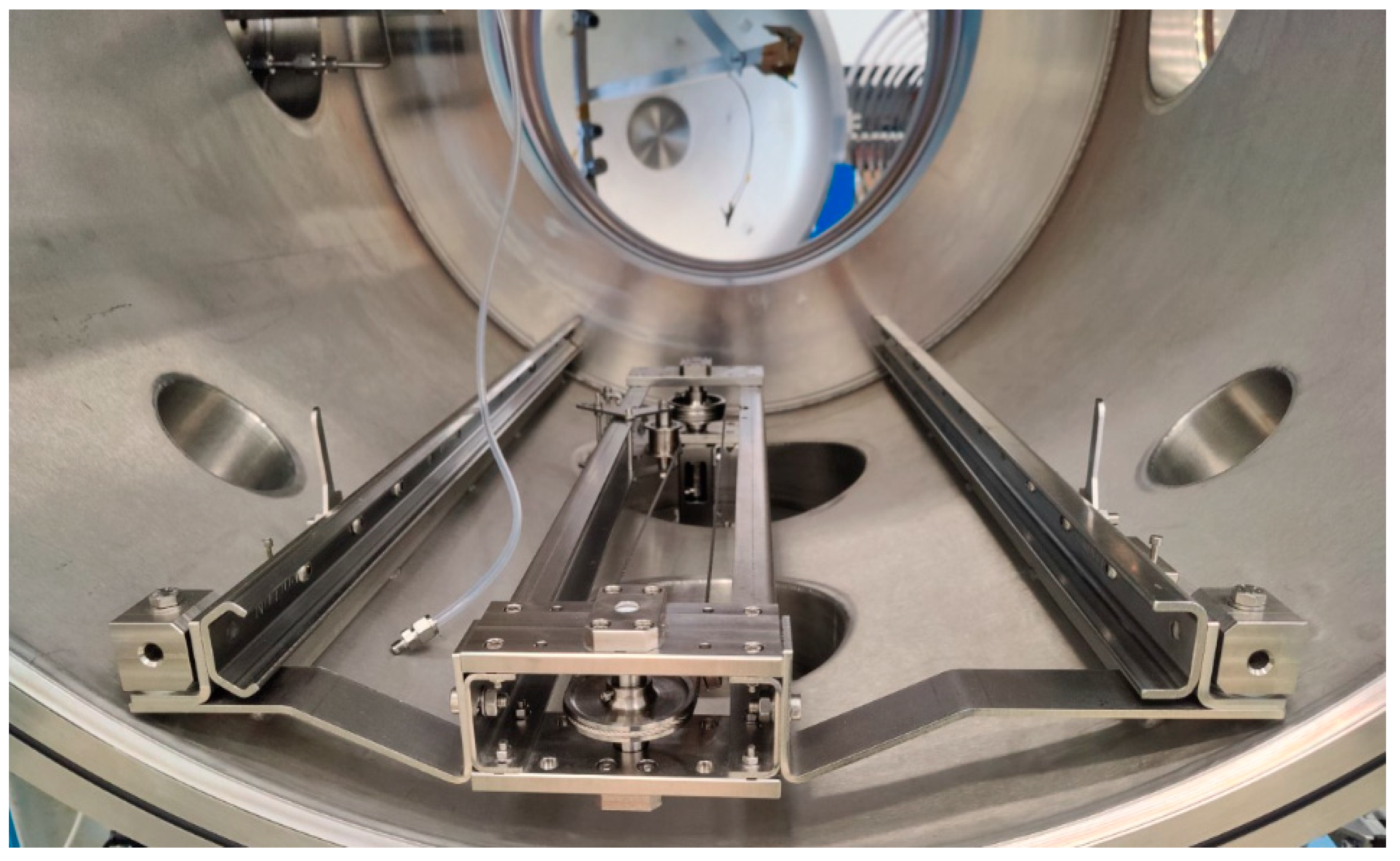
It is worth noting that the above-reported specifications of the SPF are obtained for the electric thruster. Actually, the chamber was modified to adapt it to test the chemical thruster. A value of pressure higher than or equal to 10 mbar could produce a separation of the flow inside the thruster nozzle at EOL conditions during the tests. For this reason, a new vacuum pump, capable of reaching much lower pressure, has been installed, avoiding any possibility of flow separation inside the nozzle. This dedicated pump also had a purge to dilute any possible uncombusted HTP. The system has been integrated into the vacuum chamber through the two rails shown in Figure 5.

4. Experimental Results and Discussion

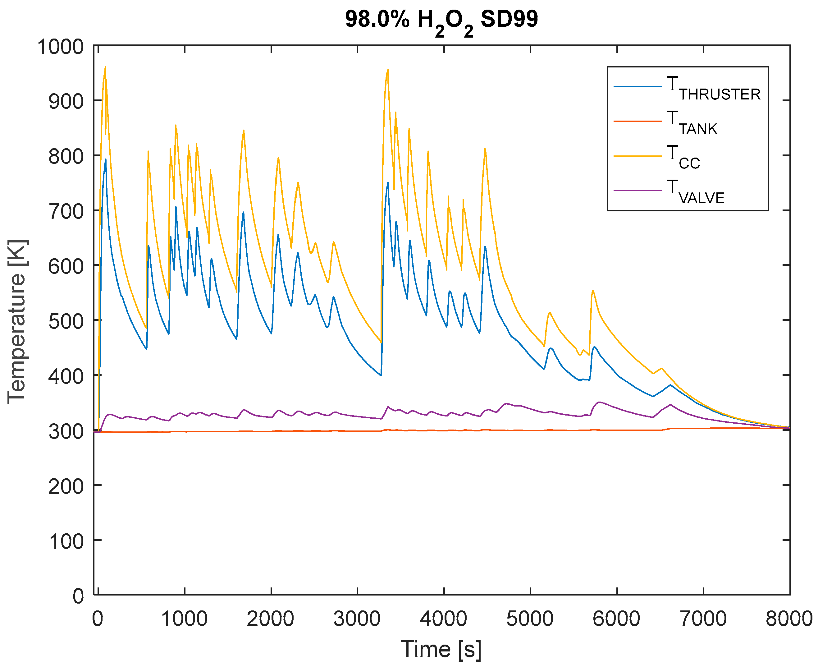
Figure 6 shows the temperature recorded by the thermocouples placed in the four main components of the propulsion system and their variation in time on each of the performed thruster firings. The gases in the thrust chamber reach a peak temperature between 700 K and 950 K during all the firing. As highlighted from the figure, the firing valve and the tank temperatures remain below the imposed operating temperature limit of 330 K for the entire duration of the test. Figure 6 also reports that the entire test lasts for about 7000 s during which the propulsion system fired in both continuous and pulsed modes. The duration and the number of pulsed firings varied during the experiment, following a precise test matrix agreed with the agency for the verification of most of the imposed propulsive requirements. During this first run, the propulsion system tank was filled only once with 0.3 dm3 of 98% wt. hydrogen peroxide, and the initial pressure was set to 22 bar. The operation of the system in blowdown mode made the pressure decrease during the run, reaching the value of 14 bar at the end of the experiment. The catalyst pellets were not changed during this first run to avoid the opening of the vacuum chamber and the disassembly of the thruster, and the total mass elaborated by these pellets was 0.160 kg at the end of the experiment.
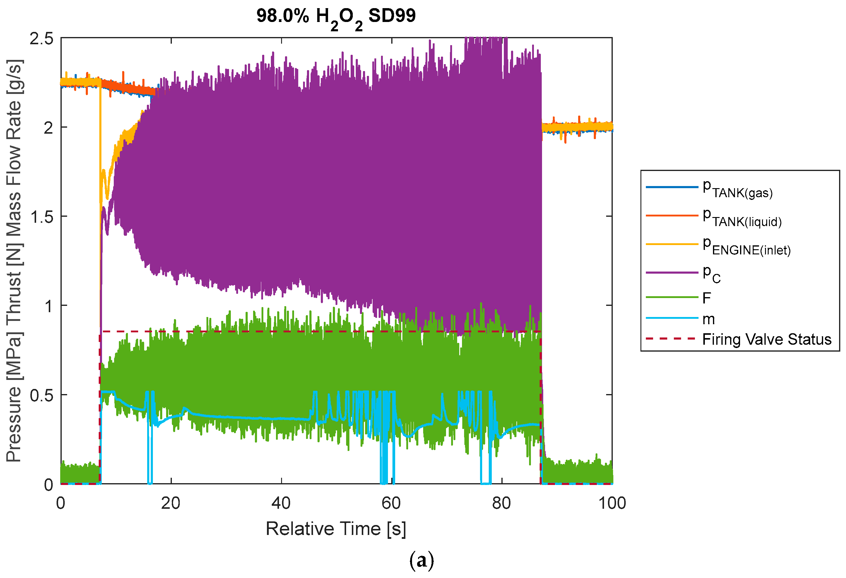
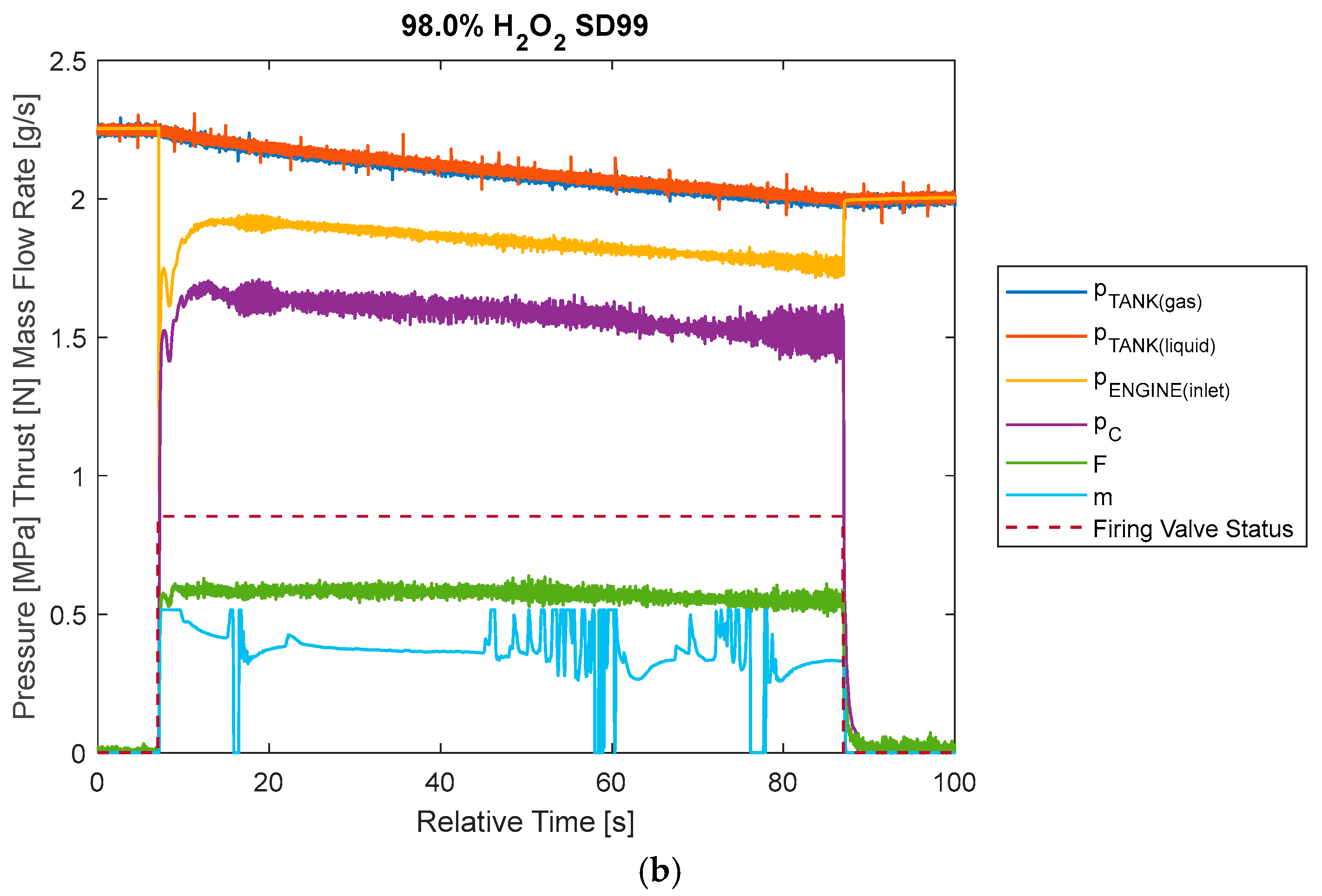
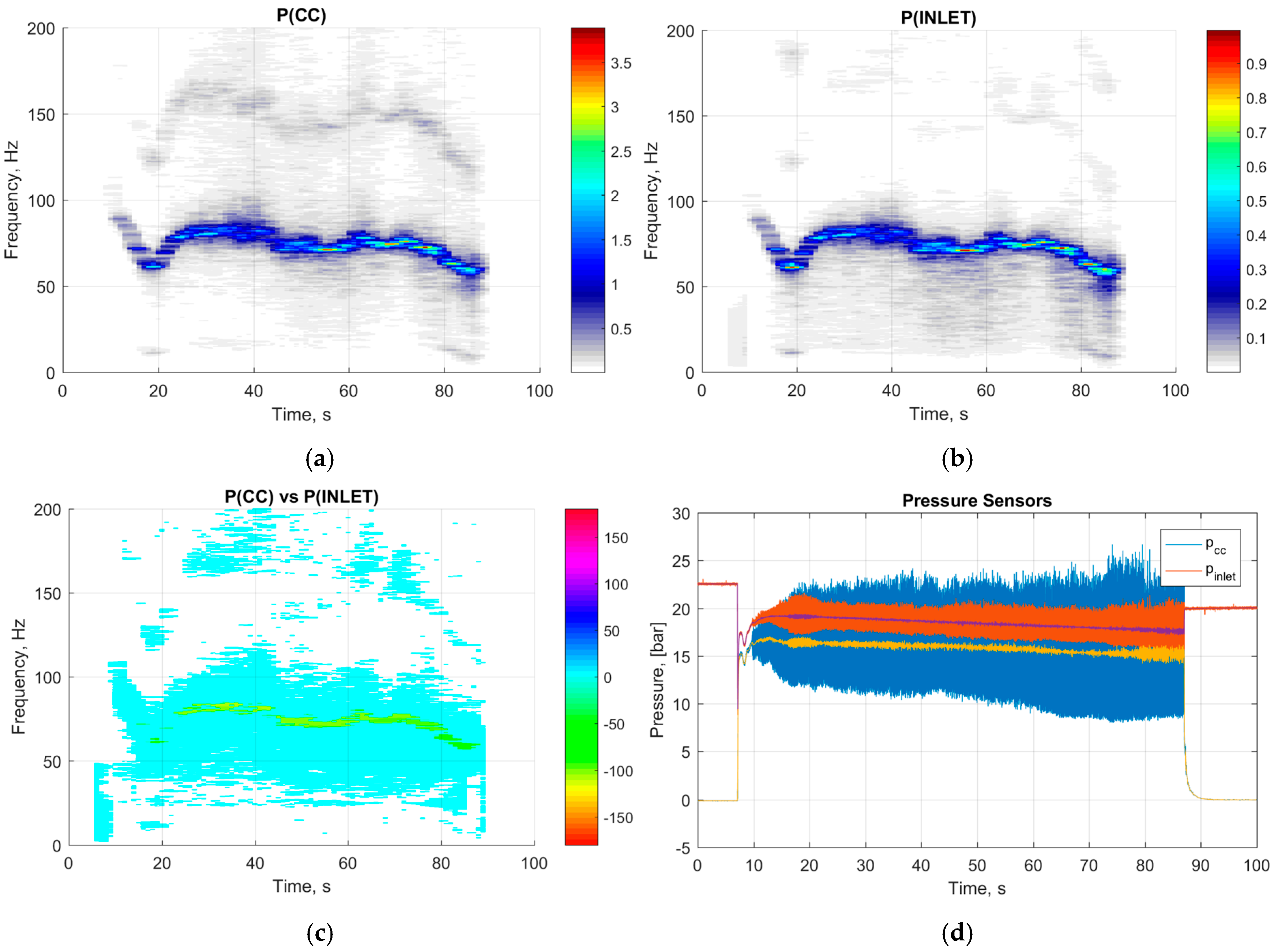
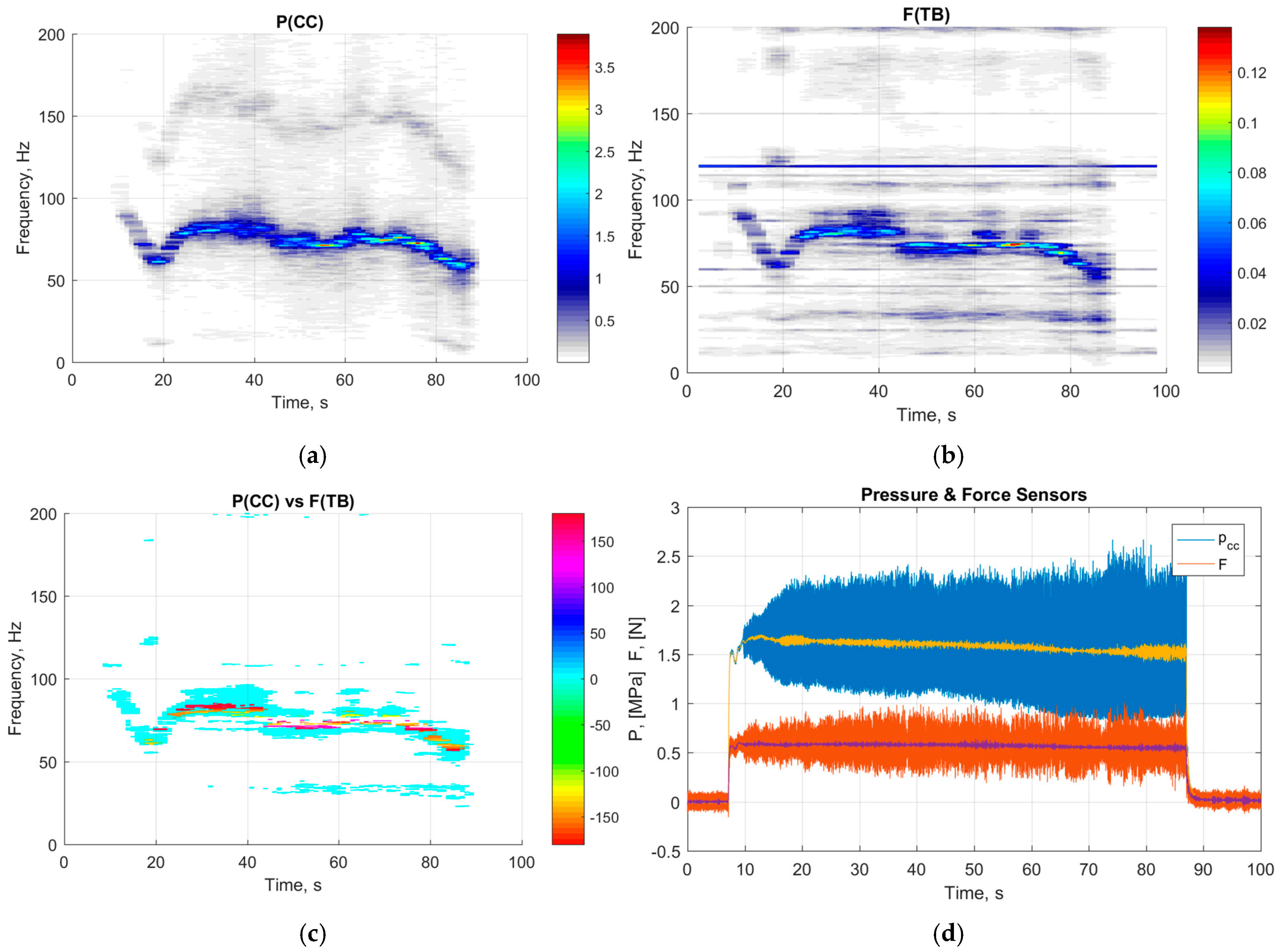
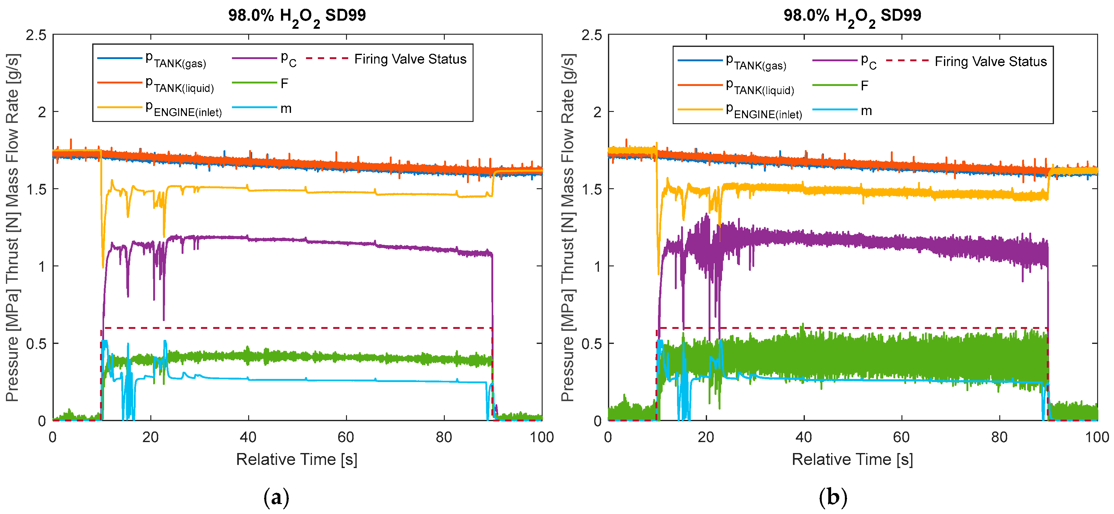
Figure 7 shows the time evolution during the first continuous firing of the main parameters from which we can determine the propulsive capabilities: the pressure inside both sides of the tank, the catalytic bed inlet pressure, the thrust chamber pressure, the thrust, and the mass flow rate. The figure on the top illustrates the no-filtered results, while the one at the bottom illustrates the filtered ones. This filtering process was necessary because of a physical instability developed inside the catalytic bed, which produced a huge oscillation of the thrust and the thrust chamber values. These oscillations were attributed to a physical instability generated inside the catalytic bed and not to a mechanical vibration of the thrust balance since both the pressure transducer inside the chamber and the load cell recorded the same oscillation frequency, as is shown in Figure 8 and Figure 9. However, looking at the filter results, the propulsion system was able to generate the required thrust and to satisfy various requirements, as indicated in Table 7.
The spectral analysis, in addition to showing the correspondence in the oscillation frequencies of the pressure sensors and the load cell, highlights the ability of the thrust balance to respond to external stimulations. In fact, for the entire duration of the test, looking at Figure 9, it is possible to see how the thrust balance recorded a force signal with a constant frequency of 120 Hz. This frequency is precisely the one at which the vacuum pump operated when left in action during the experimental campaign to guarantee the maintenance of the vacuum level in the chamber. The thrust balance was therefore also excited by the oscillation produced by the vacuum pump; however, as confirmed by the spectral analysis, this oscillation had nothing to do with the propulsive instability.
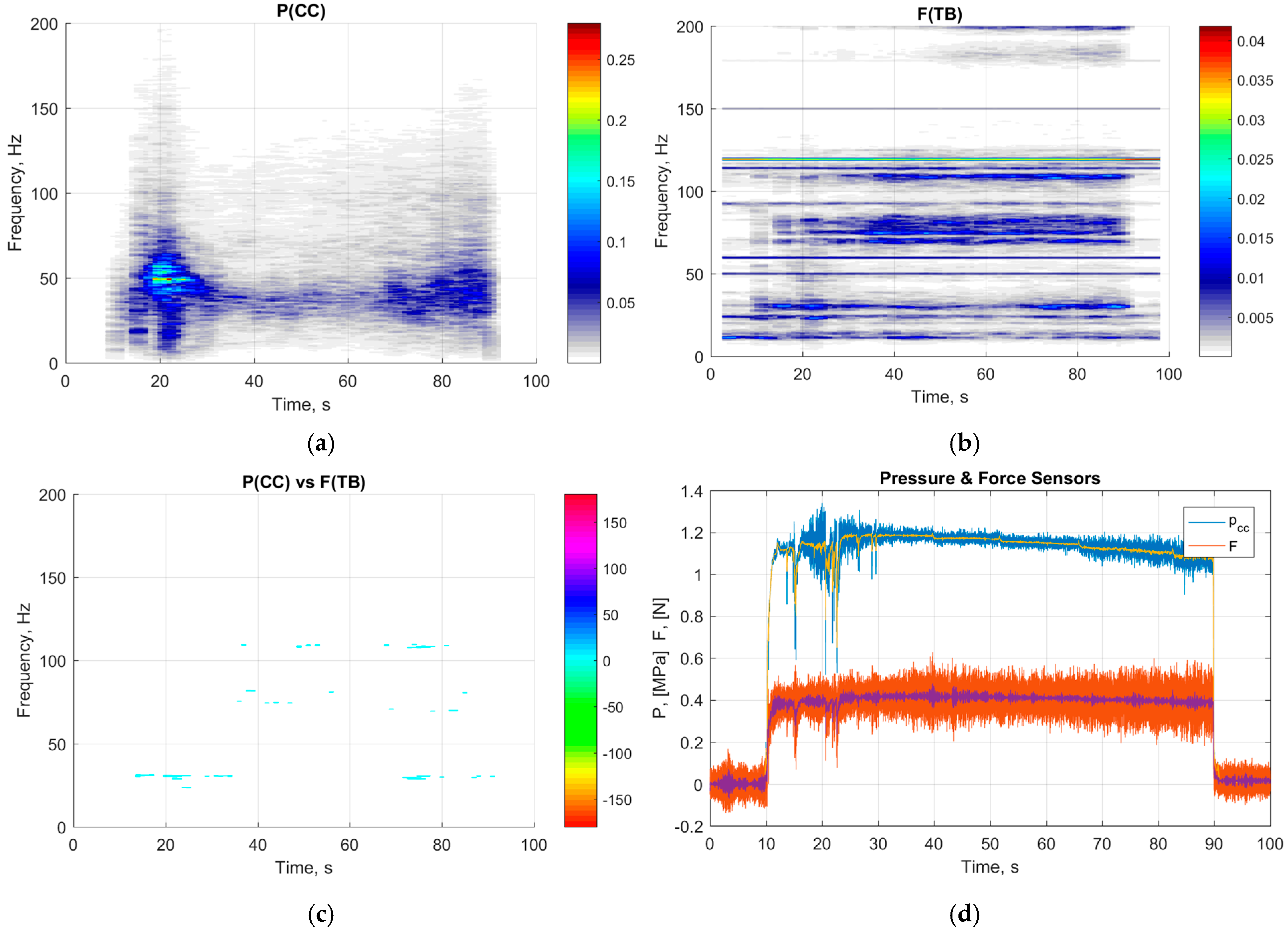
A second continuative firing gave the results reported in Figure 10. In this case, a possible catalytic bed reconfiguration due to the previous oscillations caused the suppression of the instability. The absence of the instability is visible from the recorded thrust and chamber pressure signal, which shows small oscillations due to the background noise of the thrust balance, as is understandable looking at the oscillations present even when the propulsion system is not firing at the end and at the beginning of the run (Figure 11). The steep decreases in the recorded thrust, pressure, and mass flow rate at the start of the firing were probably due to the channeling phenomena dumped by the catalytic bed reconfiguration. The performance obtained by this nominal firing showed how promising the propulsive capabilities of CHIPS are, which are reported in Table 8.
Referring to Figure 7 and Figure 10, it is worth noting the mass flow fluctuations. In Figure 7, where instability was present, these fluctuations persisted throughout the entire firing, resulting in a drop to zero in mass flow during the firing. In contrast, in Figure 10, where pressure oscillations were limited to the initial moments of firing, a drop to zero in mass flow is visible during these initial moments. The Coriolis flowmeter is capable of measuring only liquid flow; when gas or steam passes through it, it outputs a zero value; therefore, based on the drops in mass flow and pressure signals, it is plausible to assume that they were caused by a decomposition of the HTP flow upstream of the injector, resulting in the generation of steam in the line.
Figure 11 confirms the absence of instability during this firing by showing the spectral analysis of the recorded signals, both for the combustion chamber pressure and the thrust which show no coupling in the frequency domain. The 120 Hz oscillations due to the vacuum pump were still present.
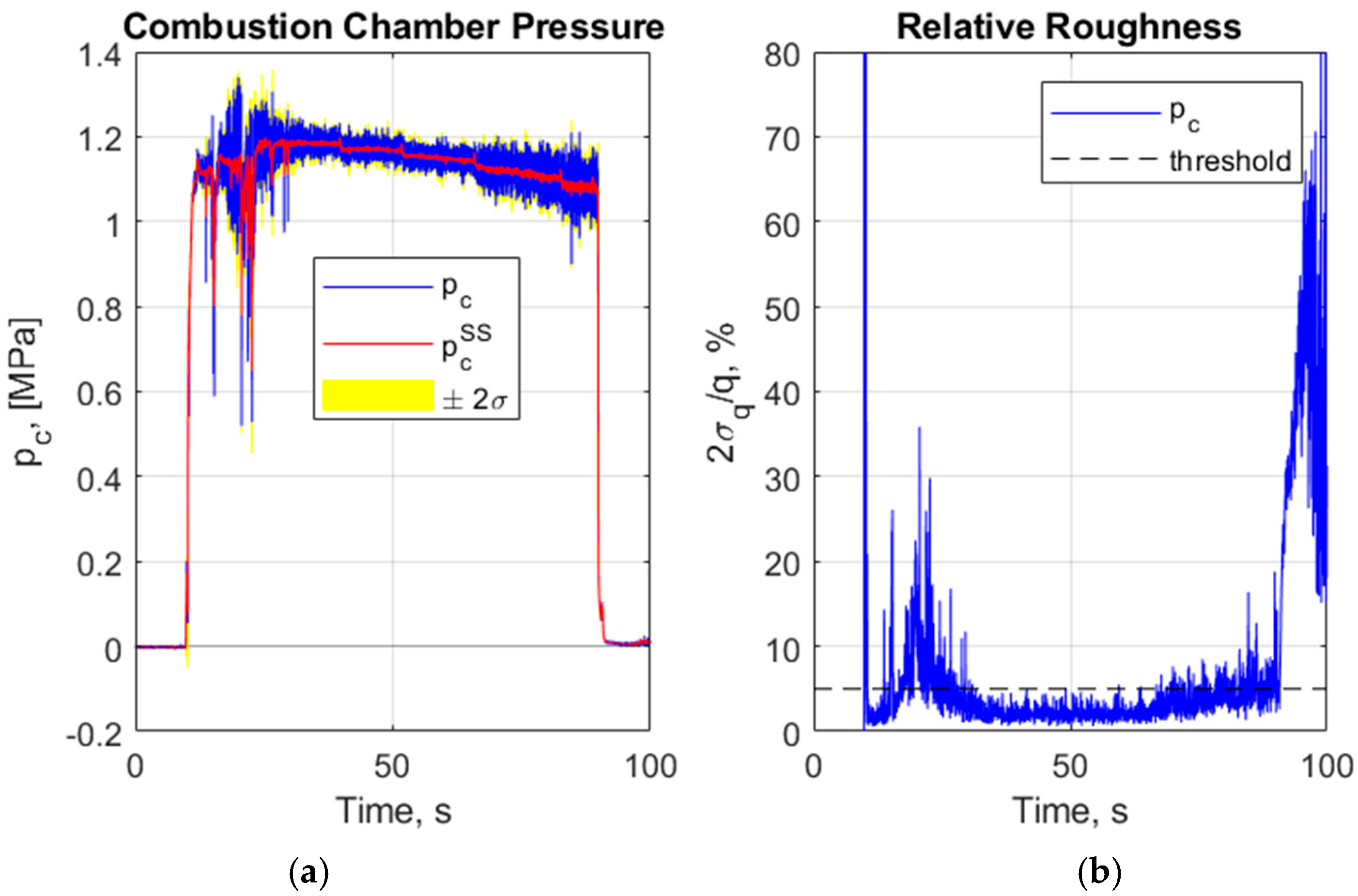
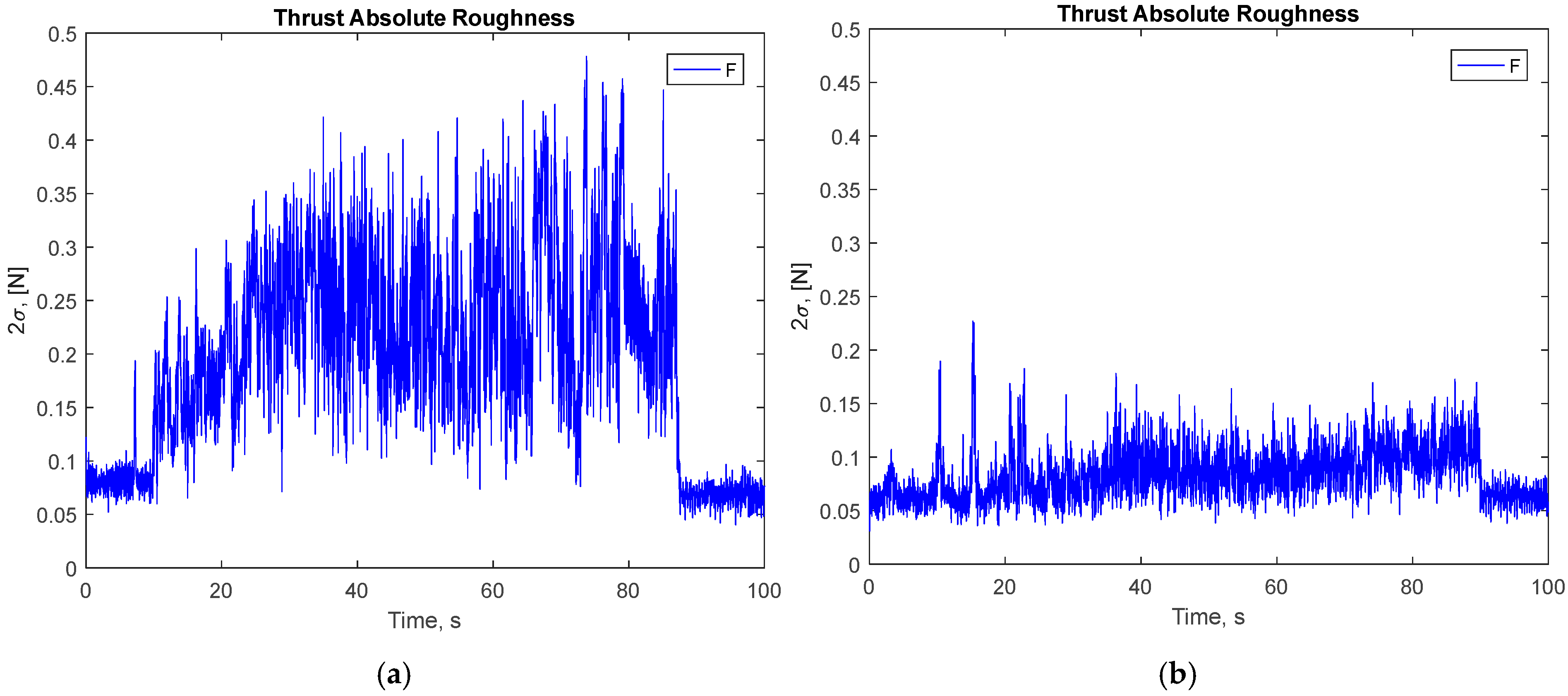
The value of thrust roughness reported in Table 8 can be better understood by looking at Figure 12 (the figure shows the combustion chamber pressure, but this quantity is strictly related to the thrust), which illustrates the total signal of the recorded pressure, and puts the composition at the steady value and the 2σ deviance as a function of time. In the right part of the figure, another graph shows the trend in the time of the pressure relative roughness, estimated using the 2σ and the nominal pressure. The graph highlights how the relative roughness was under the imposed threshold of 5% during the central period of the firing, the one after the dumping of the initial transient generated by the flow channeling in the catalytic bed. Figure 13 shows the thrust roughness signals obtained during the first (left) and second (right) firing and underlines how the presence of instability altered the actual capability of the propulsion system, since during the second firing, the obtained values lie between 0.05 and 0.1 N for the entire duration of the run, not considering the ground noise given by the thrust balance.
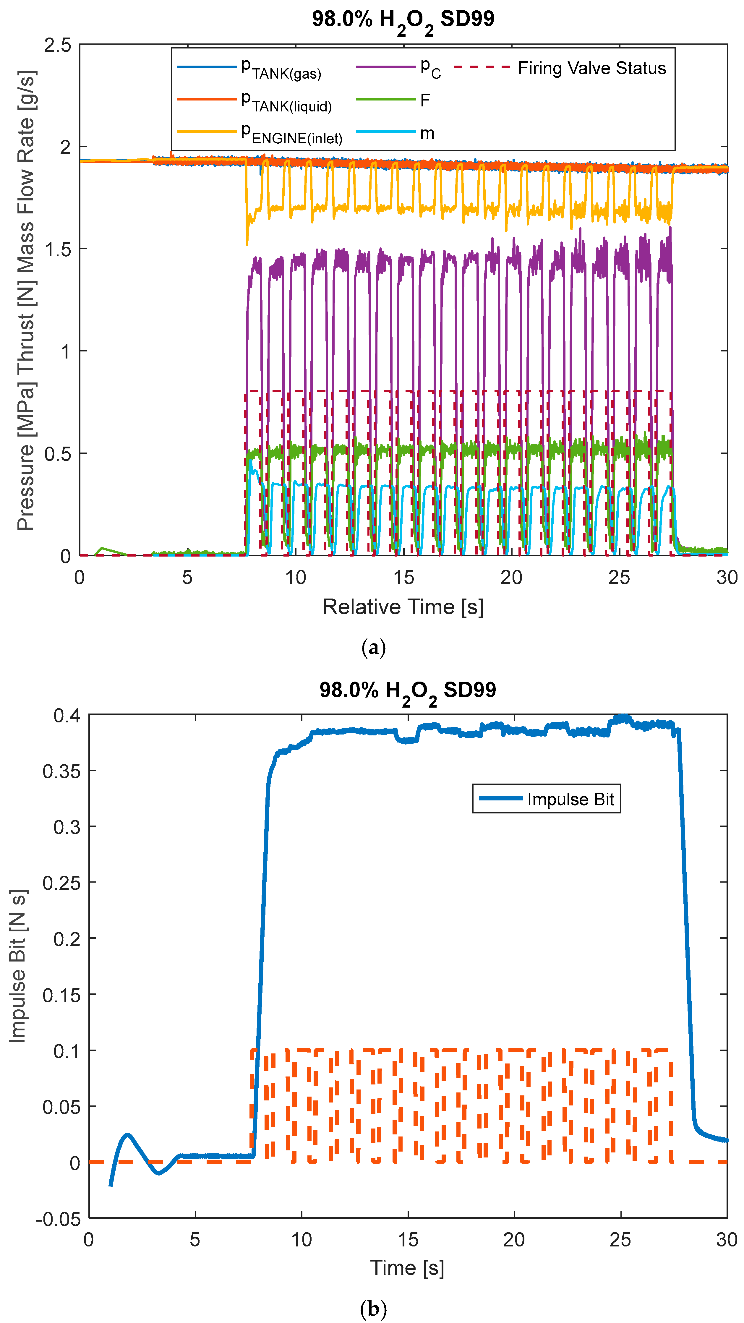
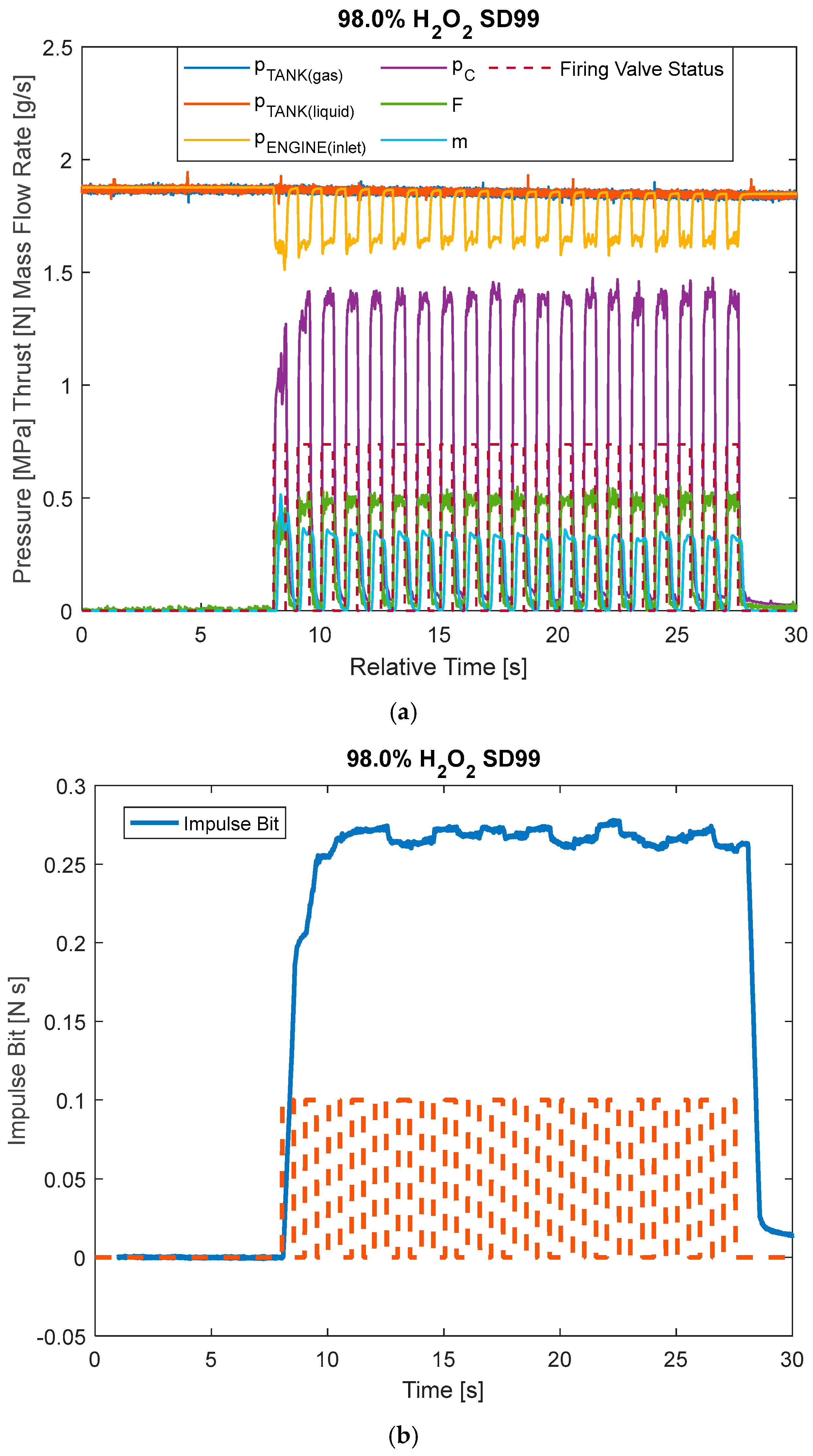
As for the pulsed firings, Figure 14 and Figure 15 show the recorded signals for the runs with 700 ms (upper) and 500 ms (lower) aperture times of the firing valve, respectively. In both cases, the generated thrust reaches the required value (0.5 N) and shows a good repeatability among the various pulses. The short duration of the pulses inhibits the setting of the instability, and the signals present a low oscillation due to the thrust balance noise. The right part of both the graphs shows the trend of the impulse bit with time, which again is repeatable from one pulse to another. The nominal value of the propulsive performance characterizing the pulse mode and obtained in all the pulsed firings is reported in Table 9, together with the corresponding firing valve aperture time. As shown in the table, the system can reach the target of 0.025 Ns of the Minimum Impulse Bit and can generate a steady value of the thrust with a low aperture time of the firing valve (50–100 ms).

5. Conclusions

A successful vacuum test campaign of the engineering model of the propulsion system described in this work highlighted how CHIPS met most of the imposed requirements and achieved the desired level of performance. This was a fundamental step in the process of further increasing the TRL of CHIPS above 5 and making it a competitive propulsive solution for SmallSats in the market. The following achievements have been accomplished in the frame of the presented experimental activity:
The MEOP was set to 24 bar and during the test, it has been proven that the system is capable of firing more than once and in pulse-mode. The performances showed that the system was able to reach 90% of the steady state thrust in nominal conditions in less than 150 ms, respecting also the limit of 0.5 N for the thrust and 160 s for the SI. The c* efficiency obtained was equal to or greater than 90%.
The system was tested in a vacuum chamber that was able to reproduce the real operational environment which is without convection and conduction with external air. The vacuum obtained inside the chamber of 10−3 mbar was enough to prevent the system from reaching flow separation conditions. Thanks to this, some components present in both the flight and engineering model were tested in their operational environment with success. Furthermore, no damage from outgassing has been detected, which is a sign that a chemical propulsion system based on HTP can be safely tested inside vacuum chambers.
All the requirements regarding the temperature of the components have been fulfilled. The firing valve and the tank maintained their temperatures below the imposed threshold, and the stand-off configuration prevented the whole system from exceeding the 60 °C limit.
The whole propulsion system is confirmed to occupy no more than 1.5U, with a mass that does not exceed 10 kg, satisfying the stringent mass and envelope requirements imposed by the target class of satellites.
It is also worth highlighting that during the first continuous run of the experiments, the system presented a catalytic bed instability. This instability did not allow us to satisfy the thrust roughness requirement due to the increasing generated oscillations. The instability, after a probable self-reconfiguration of the catalysts pellets inside the catalytic bed, the system dampened the undesired oscillations by itself, and continued steady, showing the true capabilities of the propulsion system also in terms of thrust roughness (<3% at 2σ). The cause of the instability is probably an incorrect packing of the pellets inside the catalytic bed; however, it is still unclear, since the heat coming from the thruster and reaching the injector could have led to the hydrogen peroxide boiling inside the injector, causing increasing pressure oscillation upstream in the thrust chamber; more investigations on these aspects are currently ongoing at the University of Pisa. For this reason, further studies to gain a better understanding of all the causes generating the decomposition instability are needed.

Author Contributions

Conceptualization, A.P., E.P. and S.C.; methodology, A.P., E.P. and S.C.; software, A.P., E.P., S.C. and J.S.; validation, A.P., E.P., S.C., J.S. and T.S.; formal analysis, A.P., E.P. and S.C.; investigation, A.P. and E.P.; resources, A.P.; data curation, A.P.; writing—original draft preparation, E.P.; writing—review and editing, E.P. and A.P.; visualization, E.P.; supervision, C.M.M. and T.S.; project administration, A.P., C.M.M. and T.S.; funding acquisition, A.P., C.M.M. and T.S. All authors have read and agreed to the published version of the manuscript.

Funding

This research was funded by the European Space Agency (INNOVATIVE PROPULSION SYSTEMS FOR CUBESATS AND MICROSATS) under contract No. 4000132061/20/NL/RA.

Data Availability Statement

The original contributions presented in the study are included in the article, further inquiries can be directed to the corresponding author.

Conflicts of Interest

The authors declare no conflicts of interest.

Abbreviations

The following abbreviations are used in this manuscript:
Aenozzle exit areaI.V.Initial Value
Athnozzle throat areaMEOPMaximum Expected Operating Pressure
BOLBeginning of Lifepambambient pressure
c*characteristics velocitypccombustion chamber pressure
COTSCommercial-Off-The-Shelfpintank initial pressure
CFThrust CoefficientSPFSmall Plasma Facility
EMEngineering ModelTadadiabatic decomposition temperature
EOLEnd of Lifetonfiring valve aperture time
FMFlight ModelTRLTechnology Readiness Level
FSFull ScaleUCubeSat Unit
FSOFull Scale Outputγgas specific heat ratio
ggravity acceleration constant∆vvelocity change
HTPHigh Test Peroxideεerror
IBImpulse Bitηefficiency
IspSpecific ImpulseσStandard Deviation

References

  1. ESA Space Debris Mitigation Working Group. ESA Space Debris Mitigation Requirements (ESSB-ST-U-007 Issue 1); European Space Agency: Noordwijk, The Netherlands, 2023. [Google Scholar]
  2. Lemmer, K. Propulsion for cubesats. Acta Astronaut. 2017, 134, 231–243. [Google Scholar] [CrossRef]
  3. Evans, D.D.; Price, T.W. The Status of Monopropellant Hydrazine Technology; Jet Propulsion Laboratory, NASA: Pasadena, CA, USA, 1968. [Google Scholar]
  4. Schmidt, E.W.; Wucherer, E.J. Hydrazine (s) vs. Nontoxic Propellants—Where Do We Stand Now. In Proceedings of the 2nd Conference (International) on Green Propellants for Space Propulsion (ESA SP-557) Proceedings, Sardinia, Italy, 7–8 June 2004. [Google Scholar]
  5. Nosseir, A.E.; Cervone, A.; Pasini, A. Review of State-of-the-Art Green Monopropellants: For Propulsion Systems Analysts and Designers. Aerospace 2021, 8, 20. [Google Scholar] [CrossRef]
  6. Wucherer, E.; Christofferson, S.; Reed, B. Assessment of high performance HAN-monopropellants. In Proceedings of the 36th AIAA/ASME/SAE/ASEE Joint Propulsion Conference and Exhibit, Las Vegas, NV, USA, 24–28 July 2000; p. 3872. [Google Scholar]
  7. Schoyer, H.F.R.; Welland-Veltmans, W.H.M.; Louwers, J.; Korting, P.; Van der Heijden, A.; Keizers, H.L.J.; Van den Berg, R.P. Overview of the development of hydrazinium nitroformate-based propellants. J. Propuls. Power 2002, 18, 138–145. [Google Scholar] [CrossRef]
  8. Pasini, A.; Torre, L.; Romeo, L.; Cervone, A.; d’Agostino, L. Testing and characterization of a hydrogen peroxide monopropellant thruster. J. Propuls. Power 2008, 24, 507–515. [Google Scholar] [CrossRef]
  9. Pasini, A.; Pace, G.; Valentini, D. Design and Testing of a 98% H2O2 Pulsed Thruster. Presented at the Space Propulsion 2016, Rome, Italy, 2–6 May 2016. [Google Scholar]
  10. Constantine, M.T.; Cain, E.F. Hydrogen Peroxide Handbook; Technical Report AFRPL-TR-67-144; Chemical and Material Sciences Department Research Division Rocketdyne, a Division of North American Aviation, Inc.: Canoga Park, CA, USA, 1967; p. 488. [Google Scholar]
  11. Davis, D.D.; Dee, L.A.; Greene, B.; Hornung, S.D.; McClure, M.B.; Rathgeber, K.A. Fire, Explosion, Compatibility and Safety Hazards of Hydrogen Peroxide; National Aeronautics and Space Administration NASA TM-2004-213151; NASA Johnson Space Center: Houston, TX, USA, 2005. [Google Scholar]
  12. Torre, L.; Pasini, A.; Pace, G.; Valentini, D.; d’Agostino, L.; Siciliano, P.F.; Lecardonnel, L. PulCheR–Pulsed Chemical Rocket with Green High Performance Propellants: Project Overview. In Proceedings of the VIII International Scientific Conference: “Development Trends in Space Propulsion Systems”, Warsaw, Poland, 14–15 November 2013; pp. 18–19. [Google Scholar]
  13. Pasini, A.; Pace, G.; Torre, L. Propulsive performance of a 1 N 98% hydrogen peroxide thruster. In Proceedings of the 51st AIAA/SAE/ASEE Joint Propulsion Conference, Orlando, FL, USA, 27–29 July 2015; p. 4059. [Google Scholar]
  14. Torre, L.; Romeo, L.; Pasini, A.; Cervone, A.; d’Agostino, L. Green Propellant Research at Alta SpA. In Proceedings of the ESA Space Propulsion Conference 2010, San Sebastian, Spain, 3–6 May 2010. [Google Scholar]
  15. Pasini, A.; Torre, L.; Romeo, L.; Cervone, A.; d’Agostino, L. Reduced-order model for H2O2 catalytic reactor performance analysis. J. Propuls. Power 2010, 26, 446–453. [Google Scholar] [CrossRef]
  16. Pasini, A.; Torre, L.; Romeo, L.; Cervone, A.; d’Agostino, L.; Musker, A.J.; Saccoccia, G. Experimental characterization of a 5 N hydrogen peroxide monopropellant thruster prototype. In Proceedings of the 43rd AIAA/ASME/SAE/ASEE Joint Propulsion Conference & Exhibit, Cincinnati, OH, USA, 8–11 July 2007; p. 5465. [Google Scholar]
  17. Mehrparvar, A.; Pignatelli, D.; Carnahan, J.; Munakata, R.; Lan, W.; Toorian, A.; Hutputanasin, A.; Lee, S. CubeSat design specification (CDS) REV 13; CubeSat Project: San Luis Obispo, CA, USA, 2014; pp. 1–42. [Google Scholar]
  18. Dolci, S.; Dell’Amico, D.B.; Pasini, A.; Torre, L.; Pace, G.; Valentini, D. Platinum catalysts development for 98% hydrogen peroxide decomposition in pulsed monopropellant thrusters. J. Propuls. Power 2015, 31, 1204–1216. [Google Scholar] [CrossRef]
  19. Torre, L.; Romeo, L.; Pasini, A.; Cervone, A.; d’Agostino, L.; Calderazzo, F. Performance of different catalysts supported on alumina spheres for hydrogen peroxide decomposition. In Proceedings of the 43rd AIAA/ASME/SAE/ASEE Joint Propulsion Conference & Exhibit, Cincinnati, OH, USA, 8–11 July 2007; p. 5466. [Google Scholar]
  20. Romeo, L.; Torre, L.; Pasini, A.; d’Agostino, L.; Calderazzo, F. Development and testing of Pt/Al2O3 catalysts for hydrogen peroxide decomposition. In Proceedings of the 5th International Spacecraft Propulsion Conference and 2nd International Symposium on Propulsion for Space Transportation, Heraklion, Greece, 5–9 May 2008; pp. 5–8. [Google Scholar]
  21. Shaik, R.; Bellucci, L.; Labella, L.; Calatafimi, S.; Puccinelli, E.; Pasini, A. Preliminary Screening of Catalytic Beds for Hydrogen Peroxide with Thrust Level Lower Than 0.5 N. In Proceedings of the 73rd International Astronautical Congress (IAC), Paris, France, 18–22 September 2022. [Google Scholar]
  22. Pasini, A.; Sales, L.; Puccinelli, E.; Lin, L.; Apollonio, A.; Simi, R.; Brotini, G.; d’Agostino, L. Design of an Affordable Hydrogen Peroxide Propulsion System for CubeSats. In Proceedings of the AIAA Propulsion and Energy 2021 Forum, Online, 9–11 August 2021; p. 3690. [Google Scholar]
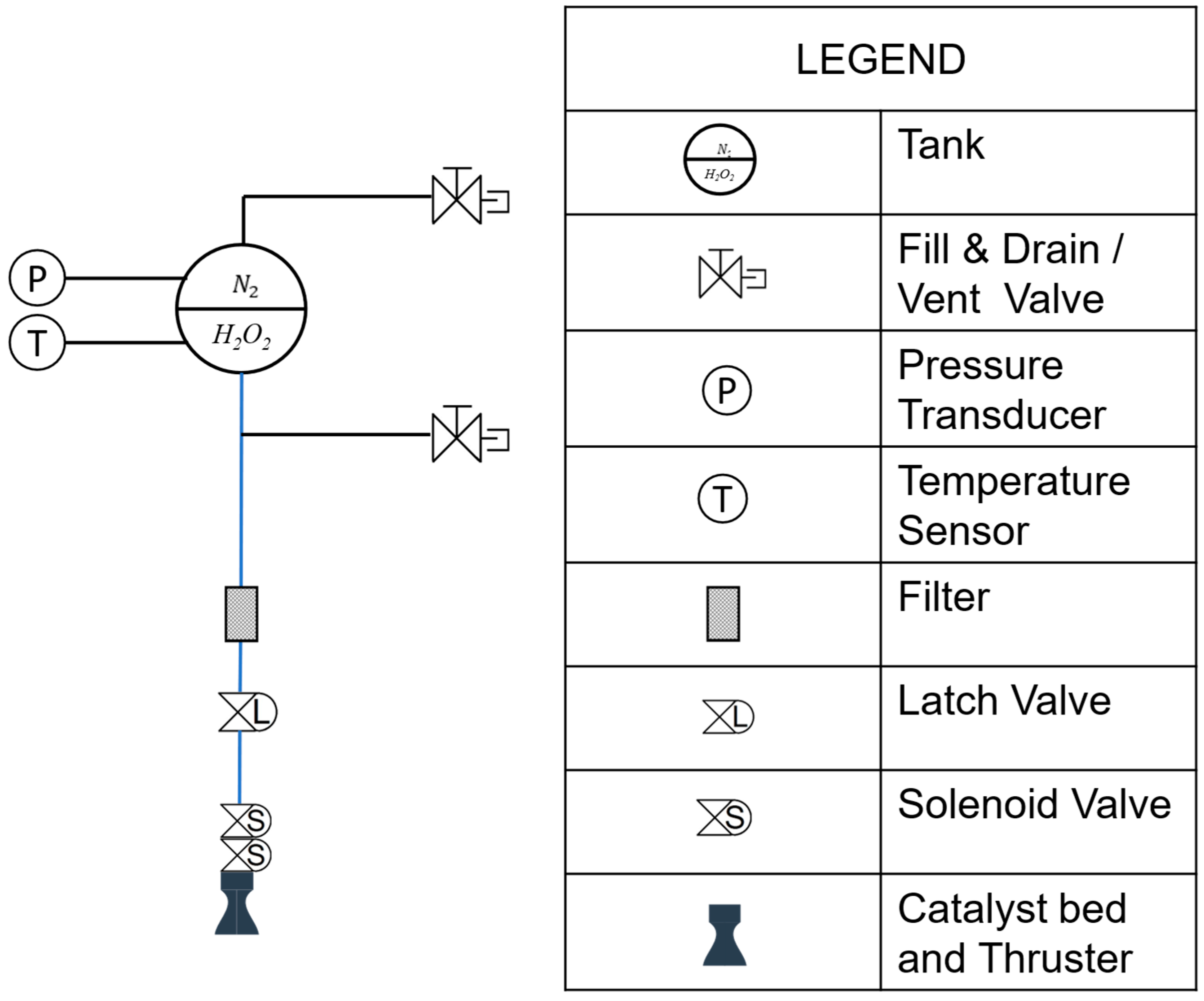
Figure 1. CHIPS flight model configuration.
Aerospace 12 01022 g001
Figure 2. CHIPS engineering model configuration.
Aerospace 12 01022 g002aAerospace 12 01022 g002b
Figure 3. CHIPS catalyst pellets and thruster.
Aerospace 12 01022 g003
Figure 4. Integration of CHIPS and the thrust balance with the SPF vacuum chamber.
Aerospace 12 01022 g004
Figure 5. Rails inside SPF hatch.
Aerospace 12 01022 g005
Figure 6. CHIPS first test temperatures history.
Aerospace 12 01022 g006
Figure 7. CHIPS first continuative Firing results: (a) unfiltered; (b) filtered.
Aerospace 12 01022 g007aAerospace 12 01022 g007b
Figure 8. CHIPS first continuative firing spectral analysis of the pressure signals: (a) combustion chamber; (b) catalytic bed inlet; (c) signal correlation; (d) amplitude comparison.
Aerospace 12 01022 g008
Figure 9. CHIPS first continuative firing spectral analysis of the chamber pressure and thrust signals: (a) thrust frequency; (b) pressure frequency; (c) signals correlation; (d) amplitude comparison.
Aerospace 12 01022 g009
Figure 10. CHIPS second continuative firing results: (a) unfiltered and (b) filtered.
Aerospace 12 01022 g010
Figure 11. CHIPS second continuative firing spectral analysis of the chamber pressure and thrust signals: (a) thrust frequency; (b) pressure frequency; (c) signals correlation; (d) amplitude comparison.
Aerospace 12 01022 g011
Figure 12. CHIPS second continuative firing chamber pressure signal (a) composition and (b) roughness.
Aerospace 12 01022 g012
Figure 13. CHIPS thrust roughness for (a) first and (b) second continuative firing.
Aerospace 12 01022 g013
Figure 14. CHIPS performance (a) and (b) impulse bit for 700 ms ton pulses. Filtered values.
Aerospace 12 01022 g014
Figure 15. CHIPS (a) performance and (b) impulse bit for 500 ms ton pulses. Filtered values.
Aerospace 12 01022 g015
Table 1. CHIPS requirements.
ParameterRequirement
PropellantHTP 98% wt.
Specific Impulse>150 s
Power Consumption≤5 W
Thrust≤0.5 N
Minimum Impulse Bit≤25 mN s
Propellant Volume≥0.3 dm3
MEOP≥24 bar
Dry mass≤1.2 kg
Volume Envelope≤2U
Material HTP compatibilityGrade I and II
Lifetime≥3 yrs
Propellant Management OperationBlow down
TRL≥3
Overall Price≤50 k€
Table 2. CHIPS thruster requirements.
ParameterRequirement
Operational Temperatures≤1000 °C
MEOP≥18 bar
Thrust≤0.5 N
c* efficiency≥0.90
Operational ModeContinuous firing
Operational ModePulse mode
Total throughput≥0.4 kg
Volume Envelope≤1U
Table 3. CHIPS thrust balance calibration values.
Thrust Balance FeaturesValue
Calibrated Full-Scale (FS)4.453 N
Standard Deviation (σF)0.014 N
Accuracy (95.4% Confidence Level)0.6% FS
Table 4. CHIPS instrumentation accuracy.
SensorRangeAccuracyPlace
Kulite ETL/T-500-375M-A (PT1)0–50 bar±0.25% FSOTank gas side
Kulite ETL/T-500-375M-A (PT1000)−50–300 °C±0.15 °CTank gas side
Kulite ETM-500-375M-SG (PT3)0–70 bar±0.25% FSOTank liquid side
Kulite ETM-500-375M-SG (PT4)0–70 bar±0.25% FSOFeeding line
Kulite XTM-190M-A (PT2)0–35 bar±1% FSOThrust chamber
TCF-A-J-3000 Tersid (TS1)−200–1200 °C±2 °CTank surface
MTS-40053-K-150-3000 Tersid (TS2)−200–1350 °C±1.5 °CFiring valve surface
MTS-40053-K-150-3000 Tersid (TS3)−200–1350 °C±1.5 °CThruster surface
MTS-40103-K-150-3000 Tersid (TS4)−200–1350 °C±1.5 °CThrust chamber
Bronkhorst M13 Coriolis (FM1)30–1500 g/h±0.2% I.V.Feeding line
Honeywell Model 13 1000 g (LD1)0–1000 g±0.7% FSOThrust balance
Table 5. CHIPS measured quantities and accuracies.
Quantity FormulaAccuracy FormulaNominal ValuesAccuracy
F σ F = 0.014 N ε F % = 2 σ F F F = 0.500   N m ˙ = 0.3115   g / s p c = 13.996   b a r c * ( t h e o ) = 1000   m / s C F ( t h e o ) = 1.82 F = 500 ± 28   m N m ˙ = 0.3115 ± 0.0062   g / s p c = 14.00 ± 0.35   b a r I s p = 163.6 ± 9.7   s c * = 900 ± 46   m / s C F = 1.78 ± 0.13 η c * = 0.900 ± 0.046 η C F = 0.980 ± 0.072
I B = 0 T p u l s e F t d t M I B = min ( I B ) ε I B % = 2 σ I B I B = 2 σ F F = ε F %
I s p = F m ˙ g ε I s p % = 2 σ I s p I s p = 2 σ F F 2 + σ m ˙ m ˙ 2
C F = F p c A t h η C F = C F C F ( t h e o ) ε c * % = 2 σ c * c * = 2 σ p c p c 2 + σ m ˙ m ˙ 2 + σ A t h A t h 2
ε η c * % = ε c * % = 2 σ c * c *
c * = p c A t h m ˙ η c * = c * c * ( t h e o ) ε c * % = 2 σ c * c * = 2 σ p c p c 2 + σ m ˙ m ˙ 2 + σ A t h A t h 2
ε η c * % = ε c * % = 2 σ c * c *
Table 6. SPF vacuum chamber specification.
SPF Vacuum ChamberElectric Thruster ConfigurationChemical Thruster Configuration
Main Chamber Dimensions (m)3.35 × Ø23.35 × Ø2
Auxiliary Chamber Dimensions (m)1 × Ø11 × Ø1
Pumps1 × roots pump (1000 m3/h)1 × Roots (Leybold—9800 m3/h)
1 × primary pump (30 m3/h)
1 × screw pump (250 m3/h)
1 × turbopump (2200 L/s N2)
4 × cryoheads (50 × 50 cm each, 29,500 L/s N2 each)
1 × cryopump (10,000 L/s N2)
1 × turbopump on the hatch (400 L/s N2)
1 × scroll pump on the hatch (30 m3/h)
Lowest Achievable Pressure (mbar)10−710−3
Beam TargetNoNo
Bake-out SystemNoNo
Table 7. CHIPS first continuative firing nominal performance.
ParameterValueThreshold Value
F (N)0.55≤0.5
Isp (s)160160
Rise-time (ms)<100150
ηc* (c*-efficiency)0.90.9
Table 8. CHIPS second continuative firing nominal performance.
ParameterValueThreshold Value
F (N)0.4≤0.5
Isp (s)160160
Rise-time (ms)<100150
Thrust Roughness<3%±5% at 2σ
ηc* (c*-efficiency)0.90.9
Table 9. CHIPS pulses train nominal performance.
ton (ms)N° Pulsespin (bar)F (N)Impulse Bit (Ns)
900 (first series)20170.5000.480
900 (second series)20140.4000.360
800 (first series)20170.5000.430
800 (second series)20140.3500.300
700 (first series)20170.5000.370
700 (second series)2013.50.3500.270
600 (first series)2016.50.5000.320
500 (first series)2016.50.4500.260
500 (second series)2014.50.2500.100
400 (first series)20160.4500.210
400 (second series)20140.2500.130
300 (first series)80160.4000.160
300 (second series)80140.3000.130
200 (first series)8015.50.4000.110
200 (second series)8014.50.0500.005
100 (first series)8015.50.4000.065
100 (second series)80140.0500.005
50 (first series)80160.2000.020
50 (second series)80140.0700.005
25 (first series)80160.2000.020
25 (second series)80140.0500.010
Disclaimer/Publisher’s Note: The statements, opinions and data contained in all publications are solely those of the individual author(s) and contributor(s) and not of MDPI and/or the editor(s). MDPI and/or the editor(s) disclaim responsibility for any injury to people or property resulting from any ideas, methods, instructions or products referred to in the content.