1. Introduction
Large stiffened cylindrical shells are widely used as load-bearing structures in underwater vehicles, submarine pipelines, and aeroengine casings to improve the structural efficiency. These structures are designed to withstand external loads, including hydrostatic pressure, axial loadings, and torsion. In particular, a large cylinder shell circumferentially reinforced by rings is usually used for structures that withstand uniform external hydrostatic pressure, of which the failure mode is indicated by one of shell yielding, local inter-frame buckling, or overall buckling of the shell and stiffeners or a combination of local and overall buckling [
1,
2,
3]. For such conventional stiffened shells, established design methodologies provided by classification societies (e.g., ABS [
4], CCS [
5]) are often sufficient. The collapse pressures under local buckling and overall buckling were calculated separately based on the classical buckling formulas, which modified reduction factors such as manufacturing tolerance and material plasticity.
Under certain extreme operating conditions, the engine outer casing may withstand circumferential external pressure or axial compressive loads, potentially leading to buckling failure. However, its structural form differs significantly from that of traditional submarine pressure-resistant structures, with the key differences as follows: First, its length-to-diameter ratio is relatively small, and the layout of internal stiffeners needs to avoid existing internal engine components, making it difficult to adopt equidistant stiffener arrangements. Second, it is usually necessary to open large-sized and closely spaced irregular flow passage holes on the cylinder; the local reinforcement scheme around these complex holes is different from that of traditional single circular holes. Finally, the most critical difference lies in the need to adopt an upper–lower split structure, which is due to the complexity of assembling internal engine components (especially the installation constraints of rotor-stator components). While prior studies have investigated non-uniform stiffener layouts and cutout reinforcement strategies, the mechanical behavior of split-structure casings under external pressure has received little attention.
It is worth noting that, based on empirical evidence, stiffener patterns often fail to fully optimize the load-carrying capacity of the structure due to initial stiffener pattern guesses that greatly limit the design space. Particularly, for those cylinder shells with a small L/R ratio, or where the arrangement of stiffeners is constrained by internal structures, nonequally spaced or nonuniformly stiffened shell structural types were preferred and achieved more flexible designability. Wang et al. [
6] proposed the concept of a hierarchical stiffened shell, which significantly reduces the imperfection sensitivity of revolution shell structures by inserting minor stiffeners in the interstices between conventional major stiffeners. Liu et al. [
7] presented a novel optimization method for stiffener layout design, which involves pre-modeling the ground stiffener structure and optimizing individual stiffener thicknesses. Gao [
8] presents a multi-regional anisotropic Material Field Series Expansion (MFSE) method for the topology optimization of stiffened revolution shell structures, directly representing regular stiffeners via anisotropic material fields and superposition functions to achieve smooth boundary descriptions and optimize stiffener layout without manufacturing constraints.
Moreover, the holes in the cylinder shell also have a great influence on the structural strength. Small holes may affect only local stresses, but large openings could affect the design’s collapse pressure. Hence, the problem of stress concentration around holes in the shell is very important and cannot be neglected. Dean [
9] studied the ring-reinforced shell with openings under external pressure by FEM, found that a series of tables of the stress concentration factors (SCF) in areas adjacent to the opening are obtained, and used these SCF modeling rules to develop the utilization of part models. Liang [
10] obtained stresses around a circular hole cut in an open shallow cylindrical shell under external pressure. The finite element method is applied to examine how curvature and thickness influence stress concentrations around the circular hole. Several researchers investigated the effects of stiffeners on the buckling behavior of cylinders having cutouts, and some of them optimized their geometry. Russo [
11] presents a numerical–analytical approach to study the effects of elliptical cutouts on stress distribution and buckling behavior in thin-walled composite cylindrical shells under tension, bending, torsion, and compressive loads, deriving empirical formulas to correlate geometric parameters with maximum stress and validate against FEM results for preliminary design optimization. Xu [
12] investigated the buckling strength of tourist submarines subjected to uniform external pressure. The result showed that the strengthened openings improve the buckling strength of the cylindrical shells with slightly higher ultimate strength than the intact one, and both the internal and external ring stiffeners improve the buckling strength of the cylindrical shells significantly due to the smaller span length between reinforcing rings. Chauhan [
13] found that a circular cutout can withstand a higher critical load in the axial compressive direction and a higher critical bending moment in comparison with elliptical and square cutouts, but the difference between the critical buckling values for all the cutouts is less pronounced under uniformly applied external pressure. Alsalah [
14] numerically investigated various stiffener configurations around cutouts and tried to recover buckling-load-carrying capacity lost due to the opening, and found that the cutout shape had minimal influence on the buckling load, whereas the size had much more influence. Tian [
15] minimized the weight of curved shells with complex shapes by optimizing the main shell thickness, the dimensions, and the number of stiffeners. Li et al. [
16] applied a similar method to optimize a thin-walled pressure vessel with variable thickness. Gokyer [
17] conducted the topology optimization of cylindrical shells with cutouts for maximum buckling strength in two levels and revealed that stiffeners on the mid lateral surfaces of the cylinder do not make a significant contribution to the buckling strength.
The current external pressure-resistant structures generally adopt full-circle cylindrical or conical configurations, and the axial connections between different structures is mainly achieved through flanges or other types of axial connection structures. Researchers mainly focus on the local structural strength of the connection methods. For example, Qiu et al. analyzed the bolt stress in flange holes [
18]. For special scenarios such as complex internal engine components that make axial assembly difficult, the external pressure structure needs to be designed as a split thin-walled structure. By contrast, split cylindrical shells, though widely adopted in compressor casings subjected to internal pressure, remain poorly understood under external loading. This split structure can cause non-circular deformation, leading to uneven circumferential stiffness and potentially affecting the buckling pressure. On the other hand, it may lead to sealing failure and leakage along the split mounting flanges. The above issues caused by the split structure have not been reported in existing literature.
This paper focuses on the analysis of an engine external protective shell casing, which will withstand external pressure loads under certain extreme operating conditions. Its main structural features include a top–bottom split cylinder structure and closely spaced non-circular holes.
Section 2 briefly describes the structure and load characteristics and the structural design and manufacturing scheme of this structure.
Section 3 introduces the finite element modeling methods employed.
Section 4 discusses the calculated results by combining them with the experimental results, with a focus on analyzing the effects of the split structure on buckling and sealing. The findings provide guidance for strength design and reliability assessment of split-structure casing.
2. Cylinder Structure Introduction
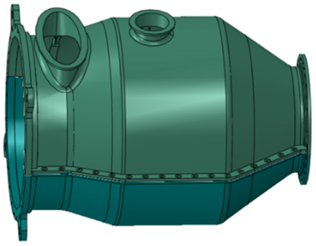
The schematic illustration of the pressure cylinder structure is depicted in
Figure 1. The structure operates at an overall temperature of 150 °C when subjected to the extreme condition of external pressure resistance, and as it is constructed from TC4 titanium alloy, this material exhibits an elastic modulus of 97 GPa and a yield strength of 725 MPa at this temperature. Its fundamental structural characteristics consist of a cone-cylinder composite shell, where the maximum diameter of the cylindrical section is 1100 mm and the overall length is 1540 mm. The shell is split into upper and lower halves to accommodate internal assembly requirements. Two flow passage apertures are situated on the upper side near the front end and the middle section separately, with cross-sections being elliptical and circular, respectively. This pressure cylinder structure is integrally subjected to external pressure, with a design load of
P0.
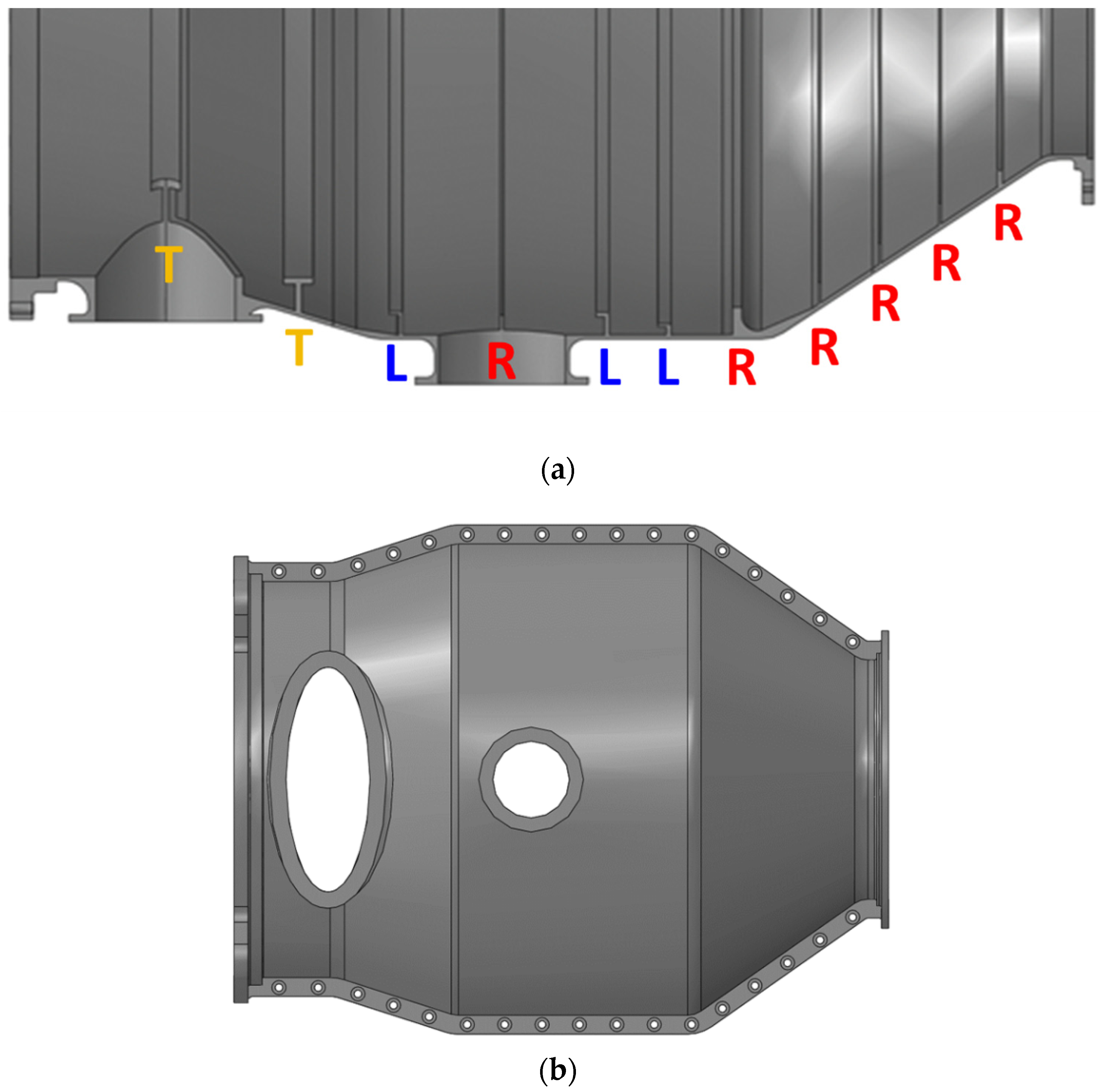
According to the design methodology for monolithic annular structures, the design of this shell structure was carried out by first using the maximum radius, overall length, and design pressure as input parameters to preliminarily determine the wall thickness specification of 7.5 mm. Then, given the spatial constraints of internal components on the stiffener layout, a non-uniform stiffener configuration was adopted for the internal ring stiffener reinforcement design, with T-shaped stiffeners of relatively large length and width employed in the front section containing apertures, and shorter or thinner L-shaped or rectangular stiffeners used in the middle and rear cylindrical and cone sections. Finally, for the two flow passage apertures, reinforcing walls and local thickness augmentation were implemented to reduce stress concentration and mitigate the detrimental effect of stiffness loss on buckling behavior (as shown in
Figure 2a). After the design of the monolithic ring structure was completed, split mounting edges were designed for the split structure. To reduce the influence of the split structure on buckling instability, the thickness of the mounting edges is increased to 15 mm, and the distance between the bolt holes and the cylindrical shell is minimized as much as possible. The split-flange arrangement is illustrated in
Figure 2b.
The pressure-resistant cylinder structure is manufactured using a combined process of segmented machining and welding, with the specific procedures as follows: First, the entire structure is divided into three segments: the inlet cone section, the middle cylindrical section, and the outlet cone section. Each segment is machined from a circular ring forging. The two perforated flow passage structures in the inlet and middle segments are machined separately, then welded to their corresponding segments via gas tungsten arc welding (GTAW). Finally, the three segments are joined into an integrated structure using electron beam welding (EBW). The machining of the split structure and mounting edges is carried out after the rough machining of the segmented circular ring forgings. After machining, the segments are first fixed with bolts, followed by further finish machining—this measure is intended to minimize the impact of machining on the structural roundness error. Measurement results after machining show that the maximum machining error of the structure is within 2.5 mm, which meets the requirements for machining errors of pressure-resistant structures specified by the CCS.
3. Buckling Analysis with FEM
Three groups of models were established in Abaqus in this paper to analyze the influence of the split mounting flange structure on the buckling failure of the overall structure. The first model, namely Model A (
Figure 3a), is a monolithic pressure cylinder without a split structure, which serves as a benchmark model primarily for comparing the effects of the split structure. The second and third groups are both split structures but differ in their treatment of the split mounting flanges: the second model does not consider actual bolt connections and fully couples the split mounting flanges with a tie constraint, while the third model accounts for actual bolt connections and contact effects. To analyze the effect of mounting edge thickness on pressure resistance performance, calculation models with a single-side mounting edge thickness of 3 mm, 6 mm, 9 mm, 12 mm, 15 mm, and 18 mm were, respectively, established for the second group (Model B) and the third group (Model C).
In the finite element calculation, the standalone pressure-resistant cylinder primarily withstands external pressure loads, with a uniform pressure of P0 applied to all external surfaces. Moreover, the four openings at the front, rear, and upper sides are not sealed, and the pressures corresponding to the areas of these inlets/outlets are applied to the corresponding flange surfaces.
The calculation includes both buckling mode analysis and simulation of the complete buckling failure process. For buckling mode calculation, a linear perturbation method is adopted, using the Linear Perturbation–Buckling–Lanczos solver to compute the critical buckling load and mode shapes ([
19] Section 6.2.3). The first 10 orders of buckling pressure and corresponding modes are obtained. Subsequently, the first five-order buckling modes are introduced as structural imperfections into a new model ([
19] Section 6.2.4), combined with an isotropic hardening plastic material model ([
19] Section 23.2.1), and nonlinear calculations are performed using the Static–Riks solver ([
19] Section 6.2.4]) to capture the complete loading and failure process including the post-buckling phase.
Notably, for the third group of models (Model C), the interface of the split mounting flange is first set as a contact pair, with hard contact specified for the normal direction and coulomb friction (friction coefficient = 0.2) [
20] for the tangential direction. All bolt models are established via “connector,” and preload loads are applied. In this model, the bolt entities are not modeled; instead, one-dimensional connector elements are used to simulate the axial loading and deformation effects of the bolts. The two endpoints of this connector element (set as reference points) are, respectively, coupled with the bolt loading surfaces on each flange via the coupling constraint. This connector adopts the translator section property, which has only axial degrees of freedom, and the stiffness in this direction is equal to the tensile stiffness of the bolt. In the first step, a preload is applied to all bolts via the connector load method to fix the upper and lower split structures through the mounting edges. Based on this stress state, Model C performs linear buckle or nonlinear buckling calculations in the second step. Since the model introduces contact and complex node coupling modules, the subspace method is then used instead of the Lanczos method to calculate the buckling pressure and mode shapes.
4. Results and Discussions
Under the design external pressure
P0, the global stress levels in the pressure cylinder remain comparatively low; therefore, this study focuses on buckling response rather than material strength. Linear eigenvalue extractions and buckling modes simulations reveal that buckling initiates at three representative regions of the structure: (1) the conical segment near the inlet, (2) the region adjacent to the hole, and (3) the conical port at the outlet (see
Figure 4). In the following sections, the detailed linear buckling results of the monolithic cylindrical shell (Model A), the cylindrical shell with axial mounting flanges (Model B), and the split cylindrical shell (Model C) will be presented and discussed, along with the influence of the mounting edge thickness.
4.1. Linear Buckling Analysis
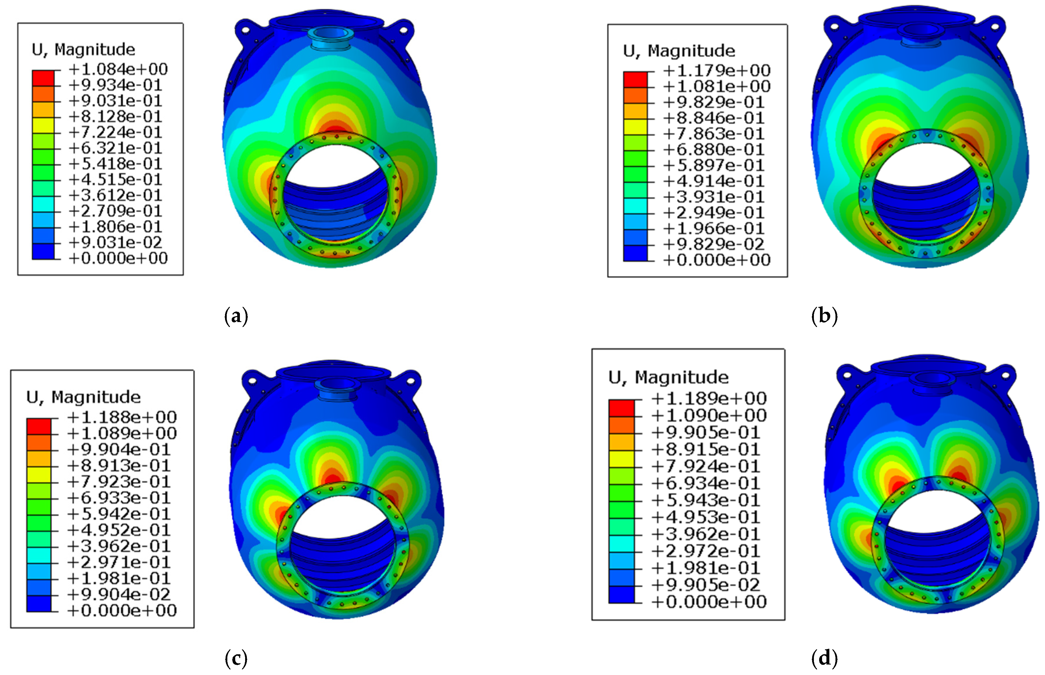
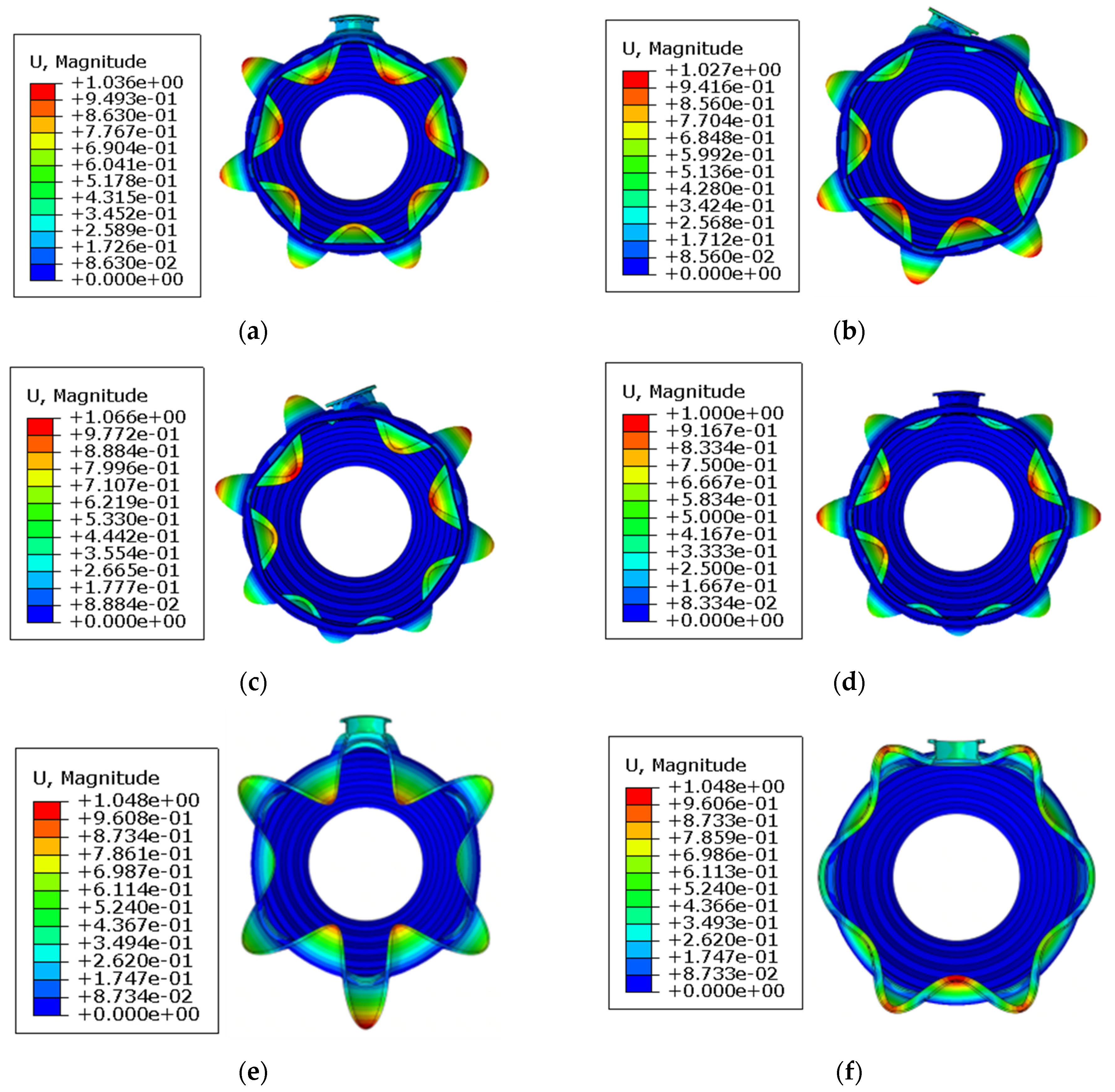
Linear eigenvalue extraction for Model A shows that the first four buckling modes localize at the outlet conical port (
Figure 5,
Figure 6 and
Figure 7) and manifest as local inter-rib buckling of the cone. The first two models feature four circumferential lobes each: the first-order lobes are aligned with the Y-Z axes, exhibiting slightly higher critical buckling pressure than the second-order mode, which is deflected by 45° from the Y-Z axes. The third and fourth modes each contain six lobes with identical critical buckling pressures.
The fifth to eighth modes localize at the circular aperture cross-section, with the fifth–sixth modes featuring seven lobes and the seventh–eighth modes featuring eight lobes. The distinctions between the fifth/sixth and seventh/eighth modes primarily arise from circumferential phase angle variations. Notably, the circular aperture does not alter the buckling mode topology, but the reinforcing ring structure mitigates local buckling deformation around the aperture.
The ninth and tenth modes present a coupled response with localization at both the inlet conical segment and circular aperture plane, displaying six lobes at the aperture and twelve circumferential lobes at the inlet cone. The primary difference between these modes lies in circumferential phase angles. Additionally, the ninth mode exhibits more pronounced buckling deformation at the inlet cone, whereas the tenth mode demonstrates comparable deformation at both locations. The reinforcing ring structure at the elliptical aperture evidently alters the circumferential buckling deformation. The buckling lobes of the inlet cone are prominent at the cylinder bottom (position opposite to the aperture), but their amplitude significantly decreases as it approaches the elliptical aperture until vanishing at the aperture location. It is noteworthy that these lobes cross the boundary between the upper and lower half-cylinders, although the buckling deformation in the upper half is barely noticeable.
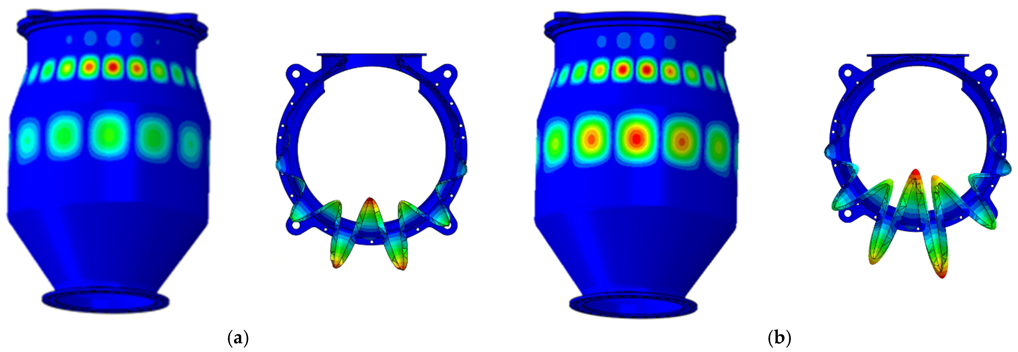
Regarding the first three buckling modes of the outlet segment, the modes of Groups B and C (
Figure 8) do not show significant changes compared with Model A. For models in group B, due to the strengthening effect of the axial mounting flanges, the critical pressures of buckling modes in the vicinity of the horizontal plane are increased. For models in Group C, which take into account the effects of mounting flange contact and bolt preloading, the overall buckling pressure may differ from that of group B models with the same mounting-edge thickness. For the first-order mode with buckling lobes on the horizontal plane, even the thinnest 3 mm mounting edge increases the buckling pressure, and the buckling pressure rises as the thickness increases. Furthermore, the buckling pressure of models in Group C is consistently lower than that of models in Group B, but the gap between the two continues to narrow. However, for cases where the buckling lobes do not coincide with the mounting edges—such as the second-order mode (with lobes positioned diagonally) and the six-lobe mode of the inlet cone segment—the following trends are observed: For models in Group B, the buckling pressure increases monotonically with the thickness of the mounting edge, but the magnitude of this increase is significantly weaker compared to that of the first-order buckling mode. For models in Group C, the buckling pressure decreases when the mounting edge thickness is 3 mm; thereafter, it increases rapidly with increasing thickness. When the mounting edge thickness reaches 6 mm, the buckling pressure of Group C models exceeds that of Model A, and between 6 mm and 9 mm, it even surpasses that of Group B models. When the mounting-edge thickness exceeds 12 mm, this buckling mode no longer appears among the top 10 buckling modes.
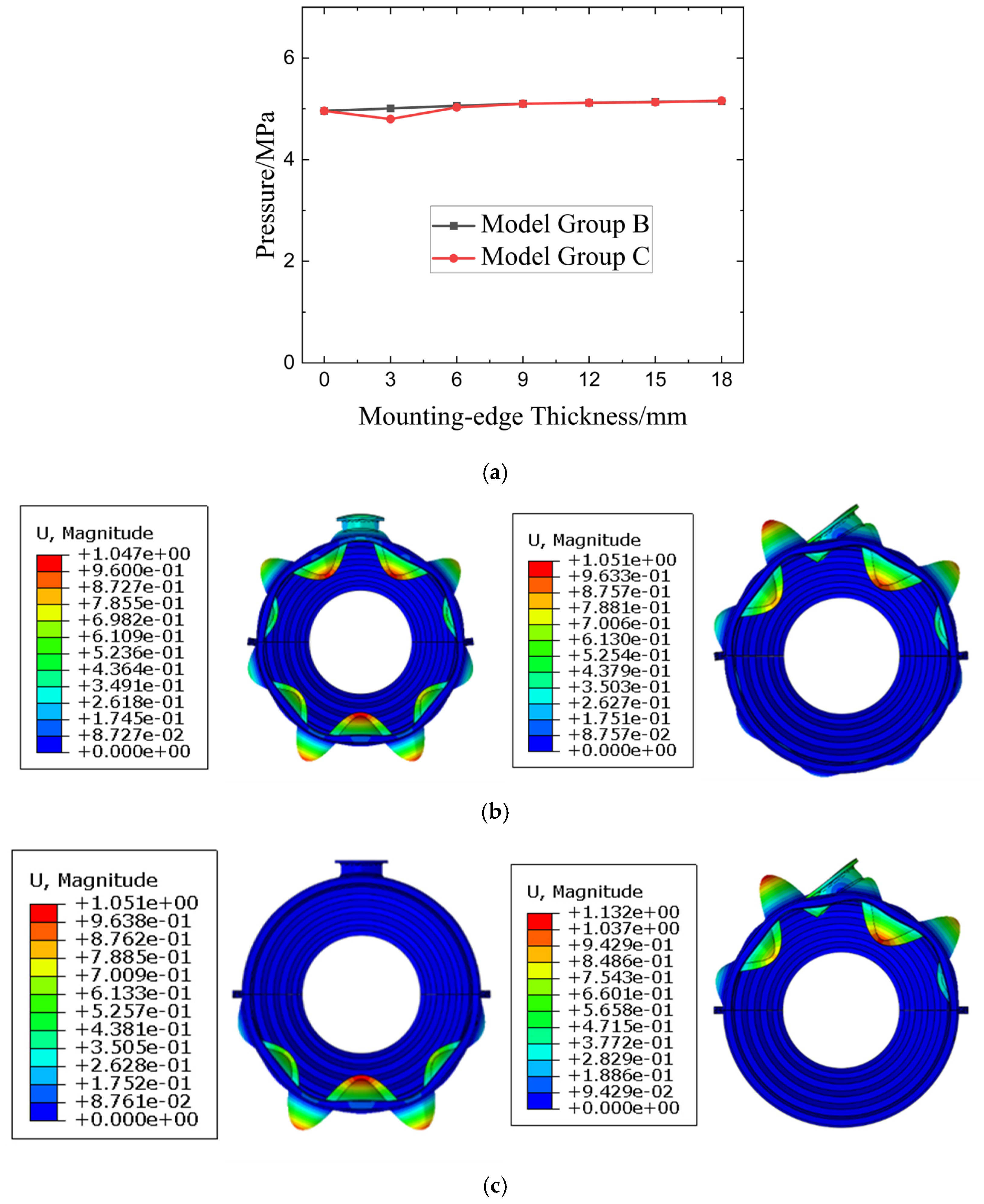
For the buckling modes corresponding to the fifth to eighth orders of Model A, the critical pressures of the corresponding models in Group B and Group C show negligible variations. Specifically, Group C exhibits a slight decrease in buckling pressure only when the mounting edge thickness is 3 mm; afterward, the buckling pressures of Group B and Group C basically coincide (
Figure 9a). This indicates that the buckling pressure is not affected by the mounting edges. A further analysis of the buckling modes in this section (taking the 15 mm thickness model as an example) reveals that the strengthening effect of the mounting edges manifests in two distinct scenarios: one where the buckling mode shape remains largely unchanged with circumferential lobe characteristics preserved, but local buckling deformation at the mounting edges is reduced (
Figure 9b, corresponding to Mode 5 of Model A), and the other where the propagation of buckling deformation is significantly attenuated by the mounting edges (
Figure 9c, corresponding to Mode 7 of Model A). For Group C, the weakening and isolation effects of the mounting edges on the buckling modes between the upper and lower halves of the cylinder are further pronounced.
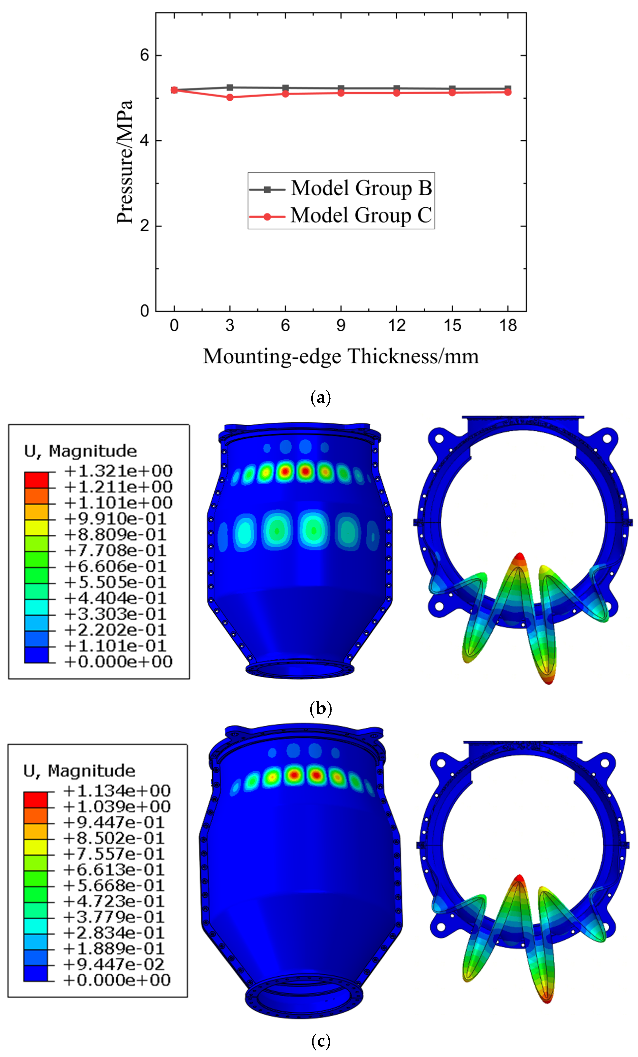
For the buckling modes occurring in the inlet cone segment, the buckling models primarily fail at the bottom of the inlet cone segment, far from the mounting edges. Thus, the buckling pressure remains almost unchanged, as shown in
Figure 10. In Group B, the result for the 3 mm mounting-edge thickness is slightly higher than that of Model A, while in Group C, the 3 mm result is slightly lower than that of Model A. With the variation in mounting-edge thickness, the two gradually approach and converge to Model A. Buckling mode analysis indicates two key findings: firstly, models with mounting edges in Group B and Group C demonstrate that the mounting edges suppress buckling deformation in both cross-sections; secondly, compared to Model A, the buckling in this region is accompanied by simultaneous buckling in the middle segment with comparable deformation magnitudes. However, for models in Group B, the buckling deformation at the inlet dominates with a magnitude much larger than that in the middle segment, while in Group C, the inlet becomes the sole location of buckling, with the buckling deformation in the middle segment disappearing entirely.
The results indicate that the mounting flanges indeed influence the structural buckling behavior, and distinct modeling approaches yield different conclusions. When the mounting flanges are only simplified as axial stiffeners, the overall structural stiffness is enhanced as the mounting-edge thickness increases, leading to a significant increase in buckling pressure—particularly for buckling modes occurring at the mounting flange locations. Moreover, the stiffeners inhibit the circumferential propagation of buckling deformation. Conversely, when accounting for both the actual bolt connections and contact stiffness of the mounting flanges, the critical pressures of buckling modes are more closely related to the mounting edges, which still increase monotonically, though the increment is smaller than that in Group B. Additionally, if the buckling lobes are not located on the mounting edges, a slight decrease in critical pressure occurs when the mounting edges are relatively thin, followed by an enhancement in pressure resistance with a higher pressure increment as the mounting-edge thickness increases. Finally, for both calculation methods, the critical pressures of buckling modes far from the mounting edges remain essentially unchanged.
4.2. Nonlinear Buckling Analysis by Riks Method
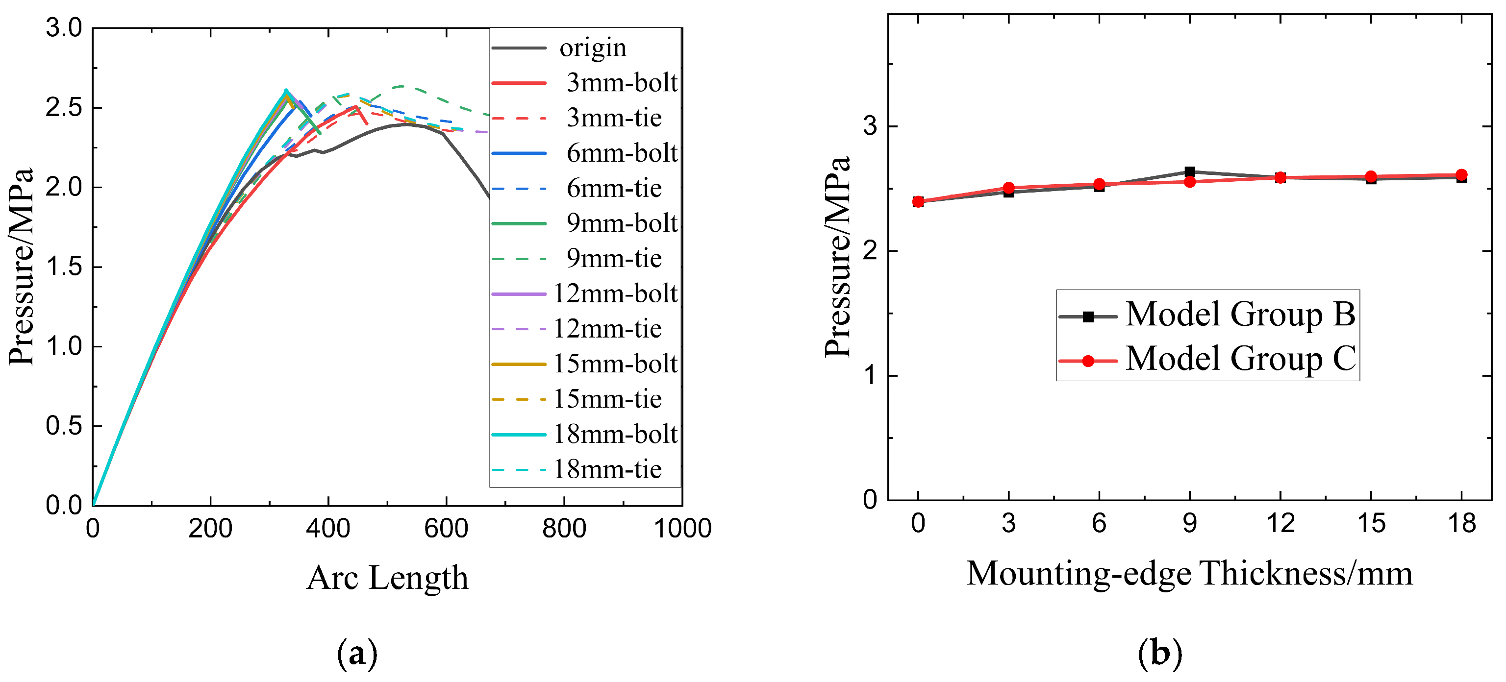
Further buckling analysis was performed on the three models using the Riks method. The pressure–arc-length curves are presented in
Figure 11a, and the ultimate pressures of all models are shown in
Figure 11b. It can be observed that Model A, which is without axial reinforcement, exhibits the lowest ultimate pressure. In contrast, increasing the thickness of the mounting edges leads to an increase in the ultimate pressure, though the increment is limited. Additionally, when dealing with the mounting edges in the modeling process, whether the bolt connections and contact effects are considered seems to have little impact on the results.
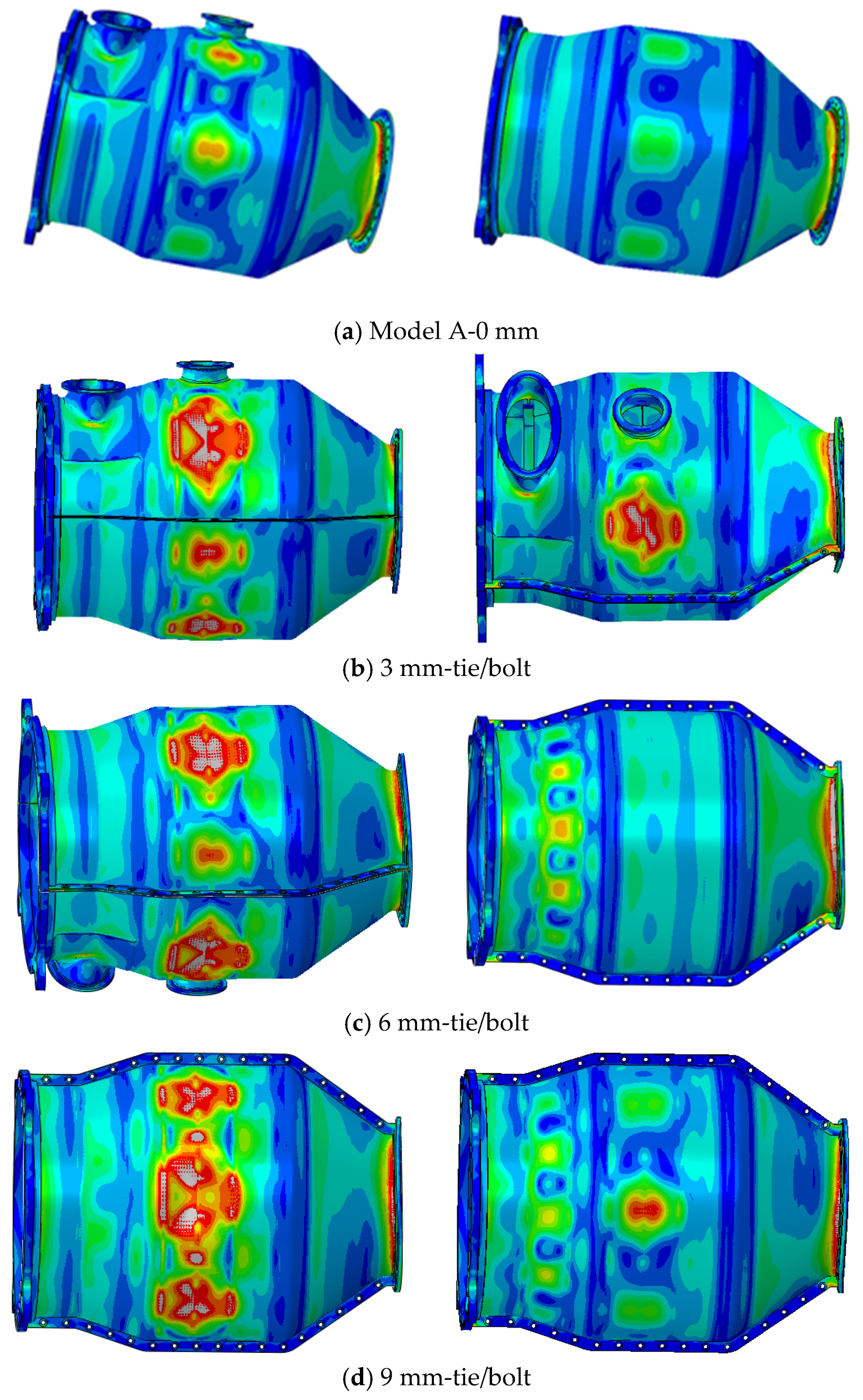
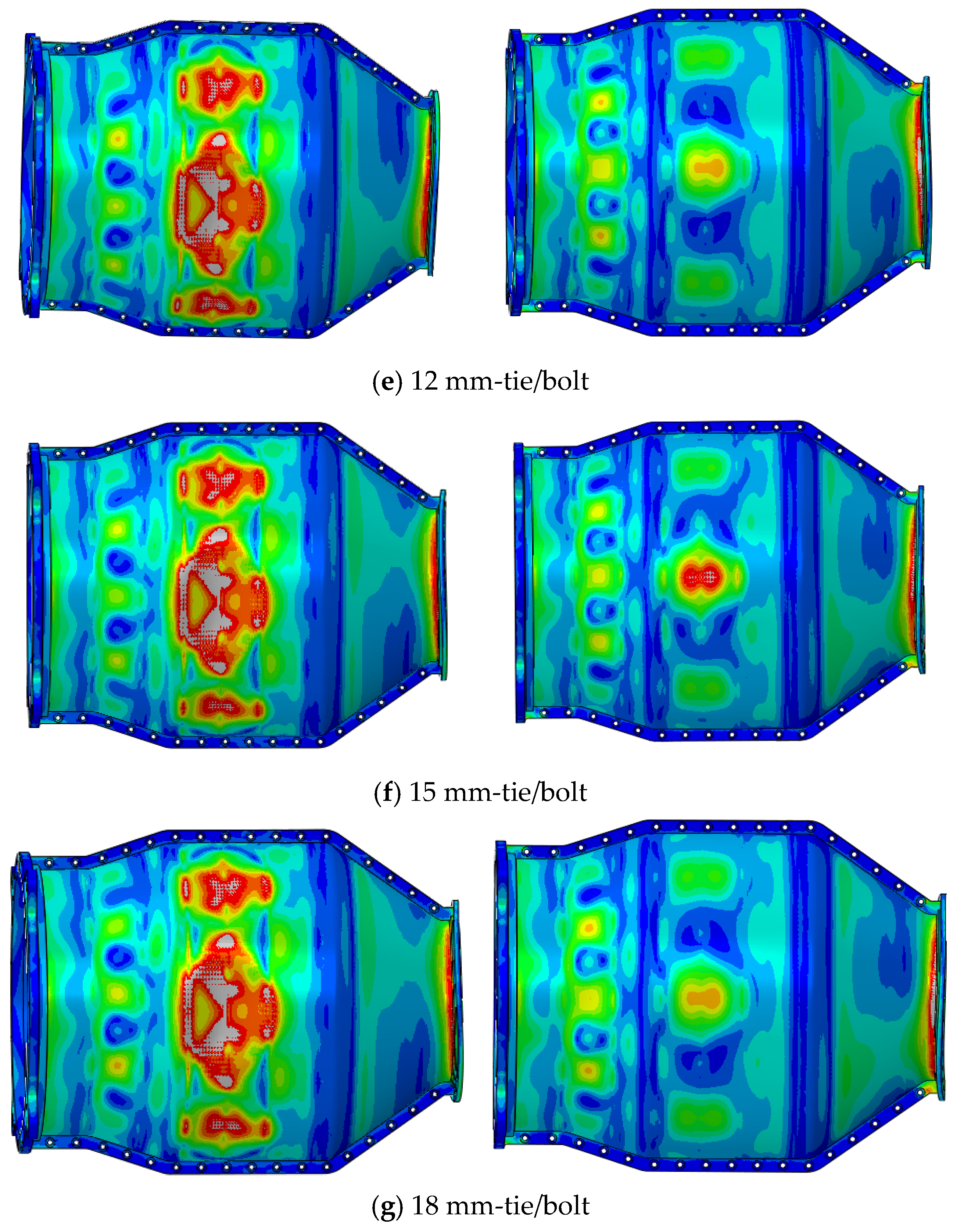
Figure 12 presents the stress contours of all models under peak load. The final failure of the vast majority of models exhibits the characteristic of multi-modal interaction. Model A shows buckling deformation in both the mid-section and outlet section, with ultimate failure occurring at the outlet section. High strain concentrates at a 45° phase angle relative to the Y/Z axes, corresponding to the second-order mode in the linear buckling analysis. For models in Group B, when the mounting edge thickness is relatively thin (3 mm, 6 mm), buckling deformation is still mainly concentrated in the mid-section and outlet section. However, when the thickness exceeds 9 mm, buckling deformation also begins to appear at the bottom of the inlet cone segment; as the thickness increases, the buckling deformation at this location becomes more pronounced. Additionally, in the outlet cone segment, the dominant buckling mode is the first-order mode, where the lobes of buckling deformation are located at the top and bottom perpendicular to the mounting edges. From the perspective of deformation magnitude, the buckling deformation degree of the mid-section is slightly greater than that of the outlet section, but the two are very close. The final failure should be caused by buckling failure in the mid-section, yet the specific failure location and its corresponding buckling mode vary: when the mounting-edge thickness is 3 mm and 6 mm, buckling failure occurs at the hole edge in the upper half; when the mounting-edge thickness exceeds 9 mm, buckling failure occurs at the bottom of the cylinder. For models in Group C, although buckling deformation also occurs in the inlet cone segment or mid-section, the final failure is caused by buckling deformation in the inlet cone segment, with the failure mode being first-order buckling (consistent with Group B). Under the action of local circumferential pressure and axial compression on the flange surface, there is an obvious tendency of vertical separation between the upper and lower halves of the cone segment in the area not fixed by bolts, which makes it more prone to large deformation and eventual buckling failure. In the design process, the integral circular design can first be adopted based on the structural prototype to ensure that the design meets the strength requirements. The structure of the mounting flanges can then be designed, as the strength of the latter structure is greater than that of the former.
4.3. External Pressure Strength Test Results and Analysis
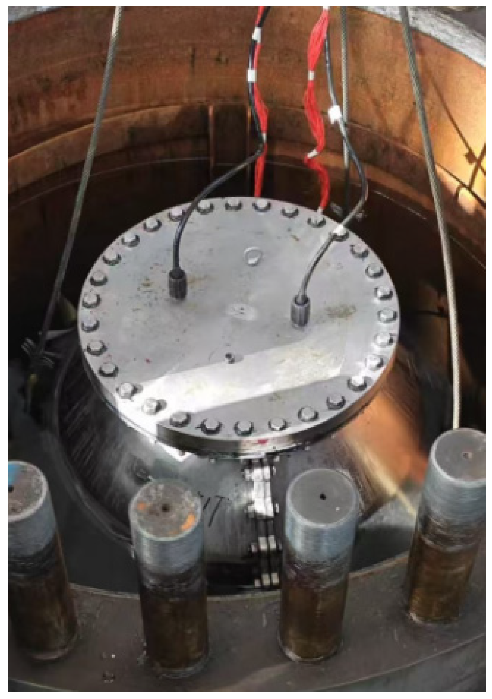
An external pressure strength test was then conducted on the cylindrical shell structures to validate the numerical analysis and investigate the actual deformation behavior, thereby deepening the understanding of the design of split pressure-resistant cylindrical shell structures. Before submerging in water, the four openings of the test specimen need to be plugged to completely isolate the interior of the specimen from the external liquid. These openings are the front and rear inlets/outlets and two flow passage apertures on the upper side. In this study, flat cover plugs were used; the shape of the plugs is consistent with the outer contour of the outlet flange, and their thickness is the same as that of the corresponding flange edge, with bolted connections. Sealing grooves were machined on the four covers, and O-rings were placed in them for sealing. The test specimen was entirely submerged in a sealed test pool with a diameter of 1.5 m and a depth of 4 m, where the maximum test pressure reached 1.6 MPa. The structure was pressurized incrementally at 0.3 MPa intervals, and the maximum load was maintained for 2 h. Post-test inspections of the specimen’s external appearance and internal sealing revealed no significant deformation or internal leakage (
Figure 13).
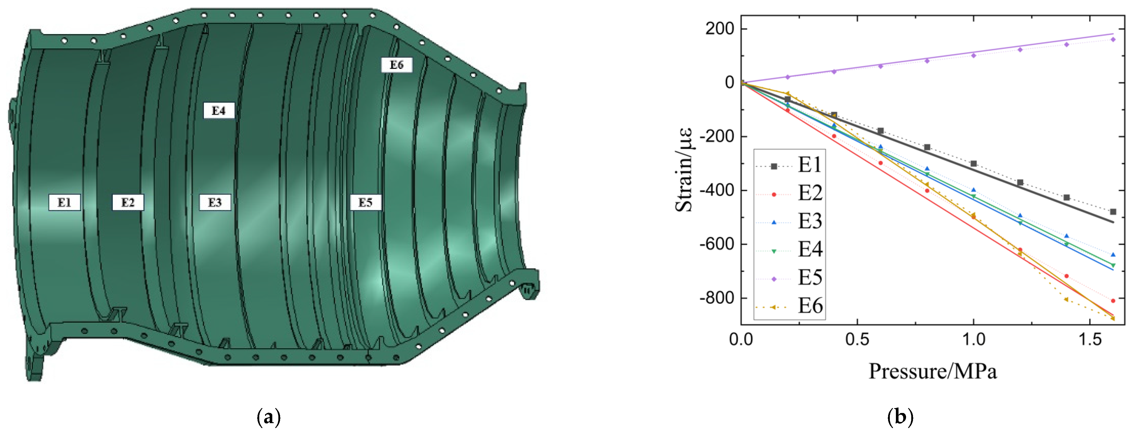
Strain measurements were performed at typical locations during the test, with the measurement points schematically illustrated in
Figure 14a. Strain measurement results (
Figure 14b) indicated that most measuring points located at shells between ribs (typical results such as points E1–E5) showed good correlation with calculated results, maintaining an essentially linear relationship. However, strain on ribs near the mounting edges E6 revealed nonlinear strain growth during the initial loading phase: the strain increment during the first load step was approximately half of that in subsequent steps. This phenomenon may be attributed to their proximity to the mounting edges and the presence of contact effects. Further examination of strain calculation results at and around E6 points confirmed the existence of initial nonlinear strain increments in areas near the mounting edges. Notably, this effect was only observed in Group C (the bolt model), which considers the contact effect. The nonlinear effect was most pronounced at the mounting edges and diminished rapidly along the circumferential direction (
Figure 15). This phenomenon may explain the discrepancies between the results of the two calculation models.
Overall, the full-scale test validates the global pressure capacity predicted by the analyses and highlights the importance of explicitly modeling flange contact for accurate prediction of initial local response and sealing-related phenomena, even though ultimate buckling loads are only modestly affected by contact in the configurations tested.
4.4. Sealing Analysis
Sealing performance for the split mounting structure is analyzed using the above nonlinear numerical simulation results under assembly preload and subsequent external-pressure loading.
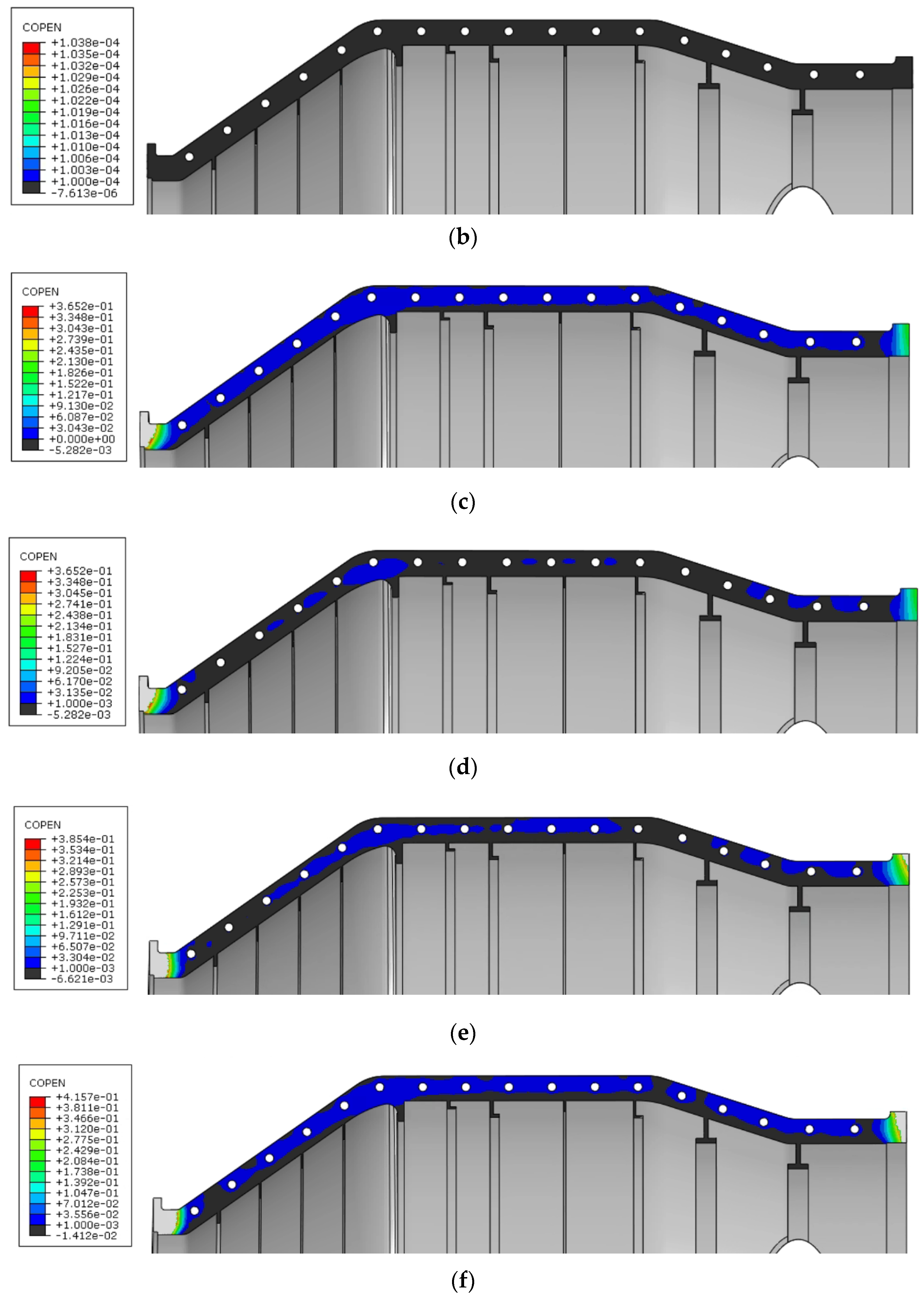
Figure 16a shows the clearance results when the mounting edge thickness is 15 mm of the mounting flange after bolt assembly, indicating that full contact is confined only to the areas around the bolt holes, with very small clearances existing between the bolt holes along the axial direction. When taking 0.0001 mm as the lower limit (
Figure 16b), the entire mounting flange appears fully sealed. After applying external pressure
P0, most positions of the mounting flange exhibit minimal clearances on the margin, demonstrating a sealing and isolating effect (
Figure 16c,d).
However, clearances exist in two locations: one is close to the inlet position, where the clearance is 0.15 mm, and conventional sealing methods are sufficient to address this issue. At the outlet position, the clearance under external pressure is larger than 0.3 mm, and the calculation model considers this area to be out of contact. At 1.3
P0 (
Figure 16e), the clearance at the inlet position further increases and is out of contact.
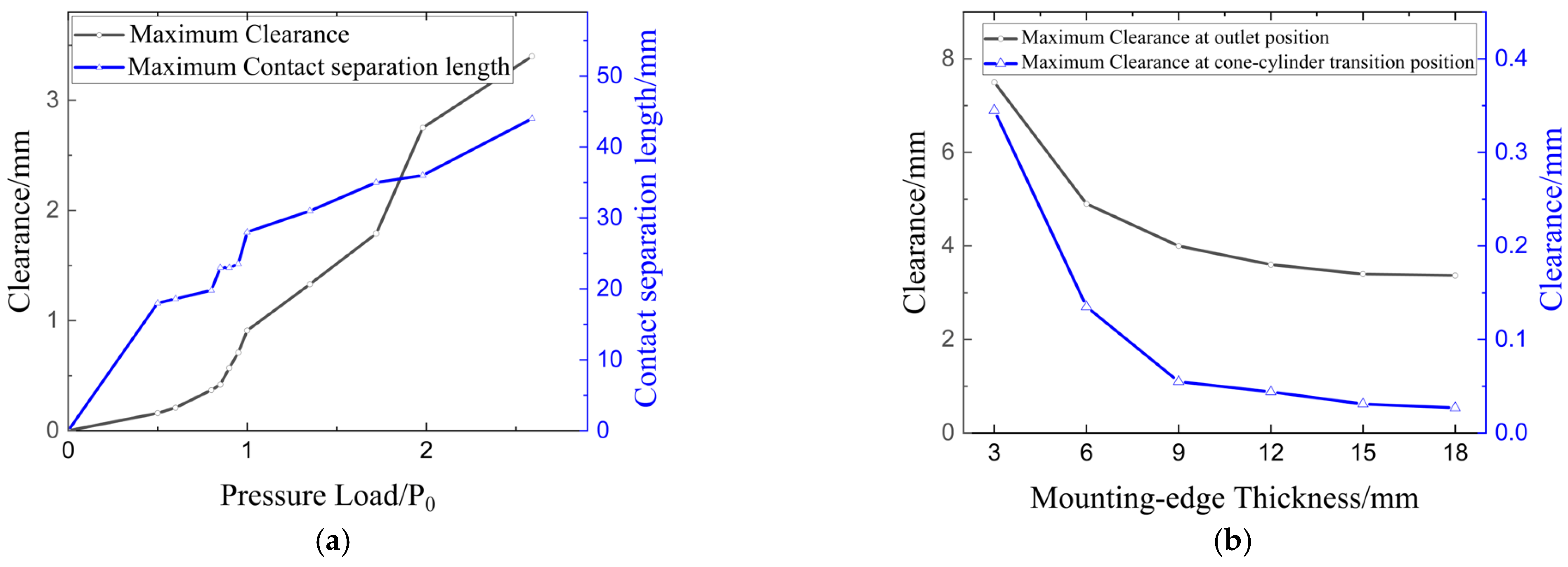
Figure 17 shows the variation in the maximum clearance and the length of the contact separation area at the outlet flange position with a pressure load. At the ultimate pressure, a leakage area approximately 40 mm long with a magnitude exceeding 0.4 mm is observed (
Figure 16f), which may exceed the operational range of the sealing rubber and cause structural leakage. It should be noted that this result does not consider the constraint effect of the corresponding flange connection structure. Nevertheless, the model still demonstrates the sealing vulnerability of the mounting flange under external pressure.
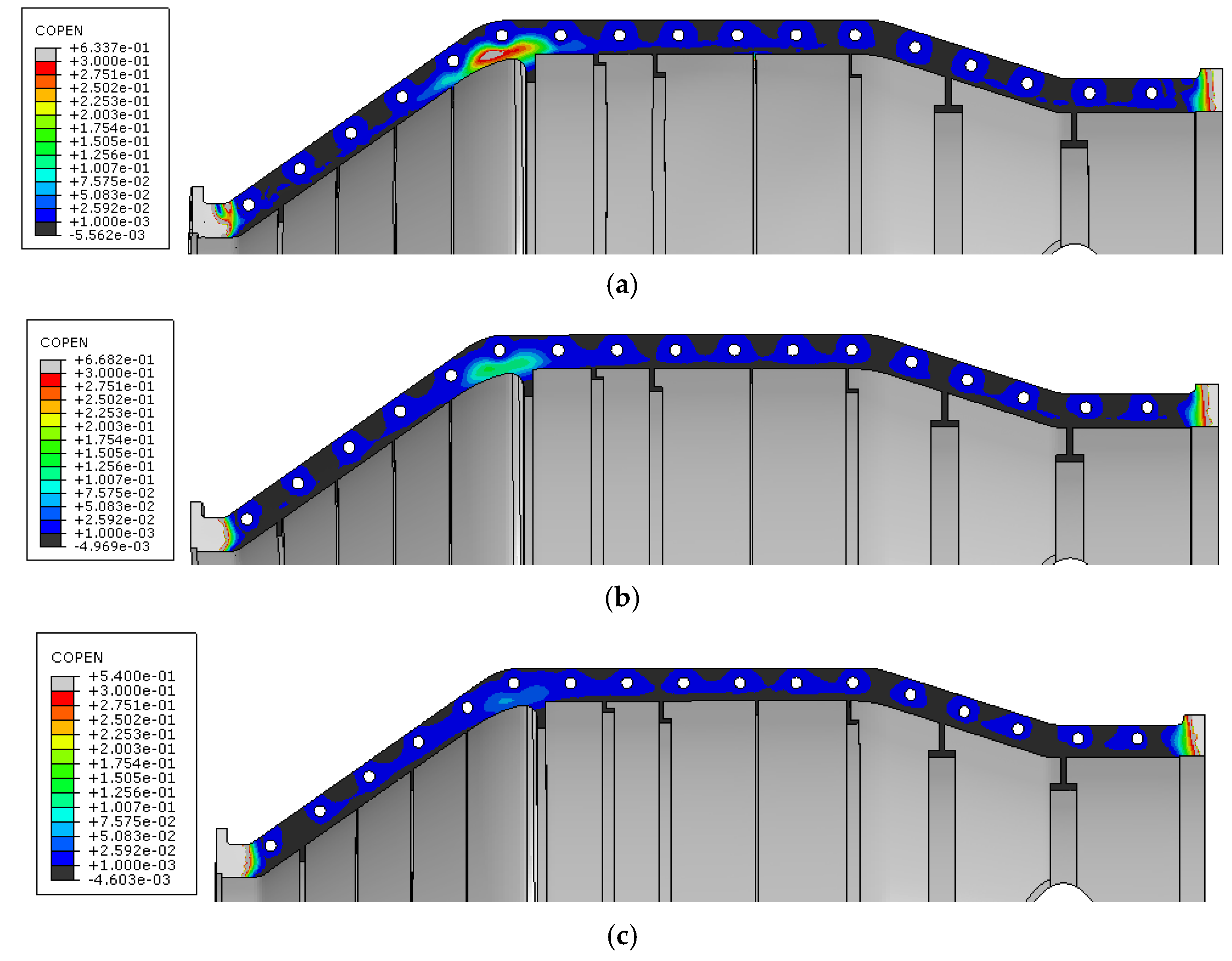
The influence of mounting edge thickness on sealing performance is shown in
Figure 18. As the thickness of the mounting edge decreases, the clearance at both the inlet and outlet ends increases, but the area of the non-contact region remains relatively similar. It is noteworthy that at the cone–cylinder transition position in the middle and rear sections, the clearance begins to increase as the thickness of the mounting edge decreases. When the thickness is 3 mm, the clearance exceeds 0.3 mm, which may lead to local leakage.
Figure 17b shows the variation in the maximum clearance at the outlet and cone–cylinder transition with the mounting edge thickness. These trends demonstrate a clear trade-off: thicker mounting edges improve sealing robustness but with diminishing returns beyond a certain thickness, and other mitigation measures (e.g., gasket design, increased preload, or additional local stiffening) may be required to ensure sealing integrity at elevated external pressures.
5. Conclusions
(1) Mode-dependent effect of split flanges: Linear buckling comparisons across Models A–C indicate that when split mounting flanges are idealized as fully integrated axial stiffeners, increasing flange thickness increases the critical buckling pressure. This strengthening effect is most pronounced for buckling modes whose lobes coincide with the flange region. When explicit bolt connections and contact are included, the mounting-edge thickness–Pcr relationship becomes more complex; nevertheless, the mounting flanges consistently reduce local deformation near the edges and tend to isolate buckling into the upper and lower halves.
(2) Nonlinear (Riks) behavior and ultimate pressure: Nonlinear Riks analyses show that the axial stiffening provided by the mounting edges increases the ultimate pressure, but the marginal gain diminishes with further increases in mounting-edge thickness. Although the full-scale external-pressure test revealed initial nonlinear local response near flange regions, the predicted ultimate pressures are broadly consistent whether or not bolt/contact effects are included. In cases where the modes controlling ultimate load are remote from the mounting flanges, the ultimate pressure of the split-flange structure remains higher than that of the monolithic cylinder and contact effects are of secondary importance. Under these conditions, a traditional monolithic design workflow remains appropriate as a first pass, followed by detailed flange design.
(3) Sealing is the primary risk: Compared with structural load capacity, sealing presents a greater operational challenge. Predicted and measured clearances indicate that leakage is most likely at inlet/outlet flange intersections where bolt coverage is incomplete; thin mounting edges may also produce non-contact gaps at the cone–cylinder transition, creating local leakage paths. These sealing failures can occur well before structural collapse and therefore require explicit consideration in design.
