Article

Flame Structure and Flame–Flow Interaction in a Centrally Staged Burner Featuring a Diffusion Pilot

1
Department of Mechanics, Harbin Institute of Technology, Harbin 150090, China
2
Department of Mechanics and Aerospace Engineering, Southern University of Science and Technology, Shenzhen 518055, China
*
Author to whom correspondence should be addressed.
Aerospace 2025, 12(11), 1019; https://doi.org/10.3390/aerospace12111019
Submission received: 9 October 2025 / Revised: 6 November 2025 / Accepted: 15 November 2025 / Published: 17 November 2025

Abstract

The pilot flame serves as the primary anchor for global flame stabilization in a centrally staged combustor. In engineering practice, it typically operates in the diffusion mode. The fuel non-uniformity and diffusion kinetics of the pilot flame may have a significant impact on the flow and flames within the combustor. The flame structure and flame–flow interaction in a centrally staged burner featuring a diffusion pilot flame are investigated in the present paper, using high-frequency CH2O planar laser-induced fluorescence (CH2O-PLIF), CH* chemiluminescence, and particle image velocimetry (PIV) measurements. The stratified flame (S-flame) and the lifted flame (L-flame) are identified under two-stage conditions. The S-flame and L-flame correspond to the separated flow and the merged flow of the two stages, respectively. Significant radial oscillation of the pilot stage airflow is also found. Extensive tests demonstrate that the pilot equivalence ratio (Φp) plays an important role in flame mode switching. Silicone droplets with extremely fine sizes are introduced into the pilot fuel to trace its transportation. When the oscillating pilot stage airflow rushes towards the lip in an instant, it can entrain the pilot fuel to reach the inner side of the main stage outlet. With a low pilot fuel supply and relatively low injection velocity, the pilot fuel and the hot radicals are more likely to be entrained and accumulate in larger amounts at the inner side of the main stage outlet. Consequently, the main stage premixed mixture can be ignited at the main stage outlet, forming the S-flame. The flame mode switches from S- to L-flame when the equivalence ratio increases to the point where the corresponding velocity ratio of pilot fuel to air (Vfp/Vap) approaches 1.0, with a reduced entrainment of the pilot fuel and radicals. Simultaneous CH2O-PLIF and flow field results show that when the main stage is ignited downstream, hot products cannot recirculate to the pilot stage outlet, causing the extinction of the pilot flame root. This paper reveals that the fuel diffusion characteristics of the pilot stage can dramatically change the flame structure. To achieve the ideal designed flame shape, the interaction between the pilot fuel and pilot air requires very careful treatment in practical centrally staged combustors.

1. Introduction

In recent decades, pollution emissions from civil aviation have attracted wide attention, driving aero-engine technology towards environmental friendliness. Adopting advanced low-emission combustor is regarded as the most direct approach to reducing emissions. Lean premixed prevaporized (LPP) combustion is considered effective for reducing nitrogen oxides [1]. However, it typically encounters the challenge of combustion instability, potentially influencing the operational stability and lifespan of the combustor. Generally, a diffusion flame will be arranged in the center to enhance the stability of LPP combustion, which is known as the pilot flame. Surrounding the pilot flame is the so-called main flame. This centrally staged combustor has achieved great commercial success and garnered extensive interest from researchers [2,3,4].
In previous studies, the flame structure has proven to be a pivotal characteristic that governs flame stabilization and the spatial distribution of heat release [5]. Extensive studies have been conducted on flame structure in single swirl combustors [6,7,8,9,10]. Meanwhile, in centrally staged combustors, independent fuel supply makes the flame of each stage more changeable, and flame–flow interaction makes the flame structure much more complicated. Consequently, modulating the two stages’ fuel distribution has emerged as the most prominent approach for generating diverse flame structures. Generally, the stratification ratio (SR), which is defined as the ratio of the pilot stage equivalence ratio to the main stage equivalence ratio, serves as a critical parameter for flame structure modulation and attracts the most attention. By changing the SR, several typical flame structures have been proposed, and corresponding thermo-acoustic instabilities [11,12,13,14,15,16], flame dynamics [17,18,19], and emission characteristics [20,21] have been investigated. Some researchers have attempted to understand the flame–flow interaction of different flame structures. Han et al. employed large eddy simulation to study flame behavior under different inlet modes [22]. They found that the main stage flow forced the pilot flame to expand, creating equivalence ratio pulsations at the confluence area. Wang et al. pointed out that the flow field at the swirler outlet and the vortex shedding from the inner shear layer mainly affect the dynamics of the pilot flame, thus influencing the stability of the entire flame [23]. While detailed investigations were conducted on flame characteristics under various centrally staged flame structures, due to the lack of test data on fuel, flow, and flame distribution, the causes of different flame structures remain not fully understood. Recent investigations by Xiang et al. have revealed that there is a sudden change in the flame shape merely when slightly adjusting the pilot stage fuel supply [24]. Fu et al. also emphasize the important role of the pilot stage in centrally staged flames [25] and find that merged flames with strong interference from the pilot flame are more likely to trigger combustion instability [26]. These findings demonstrate that the centrally staged flame structure is sensitive to fuel variations of the pilot stage. Therefore, this study focuses on variations in pilot stage operating conditions, both fuel variation and combustion mode transitions. The above-mentioned studies generally employ perfectly premixed fuels in both stages. Nevertheless, in realistic centrally staged combustors, the pilot flame typically operates in a diffusion mode. Compared with the premixed mode, different Damköhler numbers (ratios of mixing time to chemical reaction time) in non-premixed mode correspond to diverse combustion regimes, resulting in more complex heat release patterns. The flame structure is strongly dependent on flow characteristics and fuel diffusion processes [27]. As demonstrated in Cavaliere’s experimental study, non-premixed flames exhibit a more compact structure compared to premixed flames, with significantly reduced sensitivity to variations in operating conditions [28]. Actually, few studies have been carried out to investigate centrally staged flame structures with the pilot flame operating in diffusion mode. Herein, we highlight the importance of studying the diffusion pilot flame. Some existing research focuses on realistic centrally staged combustors fueled with liquid fuel at elevated temperature and pressure, where the cold and reacting flow fields, flame dynamics, and low-frequency oscillation characteristics have been investigated [29,30,31]. However, due to structural constraints, realistic centrally staged combustors usually operate in a limited number of set states, leading to relatively simplistic flow and flame characteristics.
While the critical role of the pilot stage is well recognized, the vast majority of fundamental research has been conducted under the assumption of a premixed pilot. This premise creates a significant knowledge gap, as the stabilization mechanisms and flame–flow interactions for a practical diffusion pilot are fundamentally different and remain poorly quantified. The coupled processes of fuel mixing and chemical reaction in a non-premixed mode result in combustion regimes and heat release patterns that are strongly dependent on flow characteristics, rendering extrapolations from premixed pilot studies inadequate. To bridge this gap, the present study employs a strategically designed model burner with a gaseous-fueled diffusion pilot. High-frequency CH2O-PLIF, CH* chemiluminescence, PIV, and an innovative fuel-tracing technique are integrated to uniquely visualize the pilot fuel transport and directly correlate it with the resulting flame structures and flow dynamics. Through this analysis, our work aims to elucidate the critical role of the diffusion pilot and establish a foundational understanding of its impact on centrally staged flame stabilization, thereby providing valuable insights and validation data for combustor design and numerical simulation.

2. Experimental Setup

2.1. Burner and Operating Conditions

A centrally staged burner is designed, as shown in Figure 1. Both stages employ single axial swirlers with straight vanes inclined at 30° to generate swirling flow in the burner. The swirl number SN is calculated as
S N = 2 3   tan θ   1 ( D i   /   D o )   3 1 ( D i /   D o )   2
where θ is the vane angle, and Di and Do denote the inner diameter and outer diameter of the swirler. The estimated swirl numbers for the pilot swirler and the main swirler are 0.5 and 0.46, respectively. The two stages are separated by a lip structure. Air and methane are fully premixed before entering the main stage channel, so the main flame can be regarded as premixed combustion. The pilot stage methane is not premixed with the pilot stage air. Instead, it is supplied through the central pipeline inside the pilot swirler and ejected from an annular slot. This annular slot nozzle has a height of 1.0 mm, an outer diameter of 7.4 mm, an injection semi-cone angle of 10°, and is located 5 mm from the exit plane of the dome. Given the air–fuel arrangement in the pilot stage, the pilot flame can be considered to operate in diffusion mode. A square confinement with a width of 70 mm and a length of 105 mm serves as the flame chamber. The end of the confinement features a no-contraction design, and the side walls are made of quartz glass to ensure optical accessibility. For the illustrative purpose of spatial location, the coordinate origin is set at the center of the dome outlet plane, and the directions are shown in the figure using red arrows.
The burner operates at atmospheric pressure. The detailed studied conditions are presented in Table 1. The total mass airflow rate is consistently maintained at 4 g/s, and the air ratio between the main stage and the pilot stage is 8:1, a typical value in practical combustors. The air and methane supplied to each stage are independently regulated by four mass-flow controllers (Alicat, Arizona, USA, MCR Series) with an accuracy of 1.5%. This allows for the flexible adjustment of the SR. In Cases 1 to 5, only the pilot stage is fueled, which is designated as pilot-stage conditions. In Cases 6 to 10, both stages are fueled, which is referred to as two-stage conditions. Under two-stage conditions, the total equivalence ratio (Φtotal) is always maintained at 0.9, and the SR varies from 0.5 to 2.5. A higher SR value indicates an increase in the pilot stage equivalence ratio (Φp) and a decrease in the main stage equivalence ratio (Φm).

2.2. High-Frequency Optical Measurement

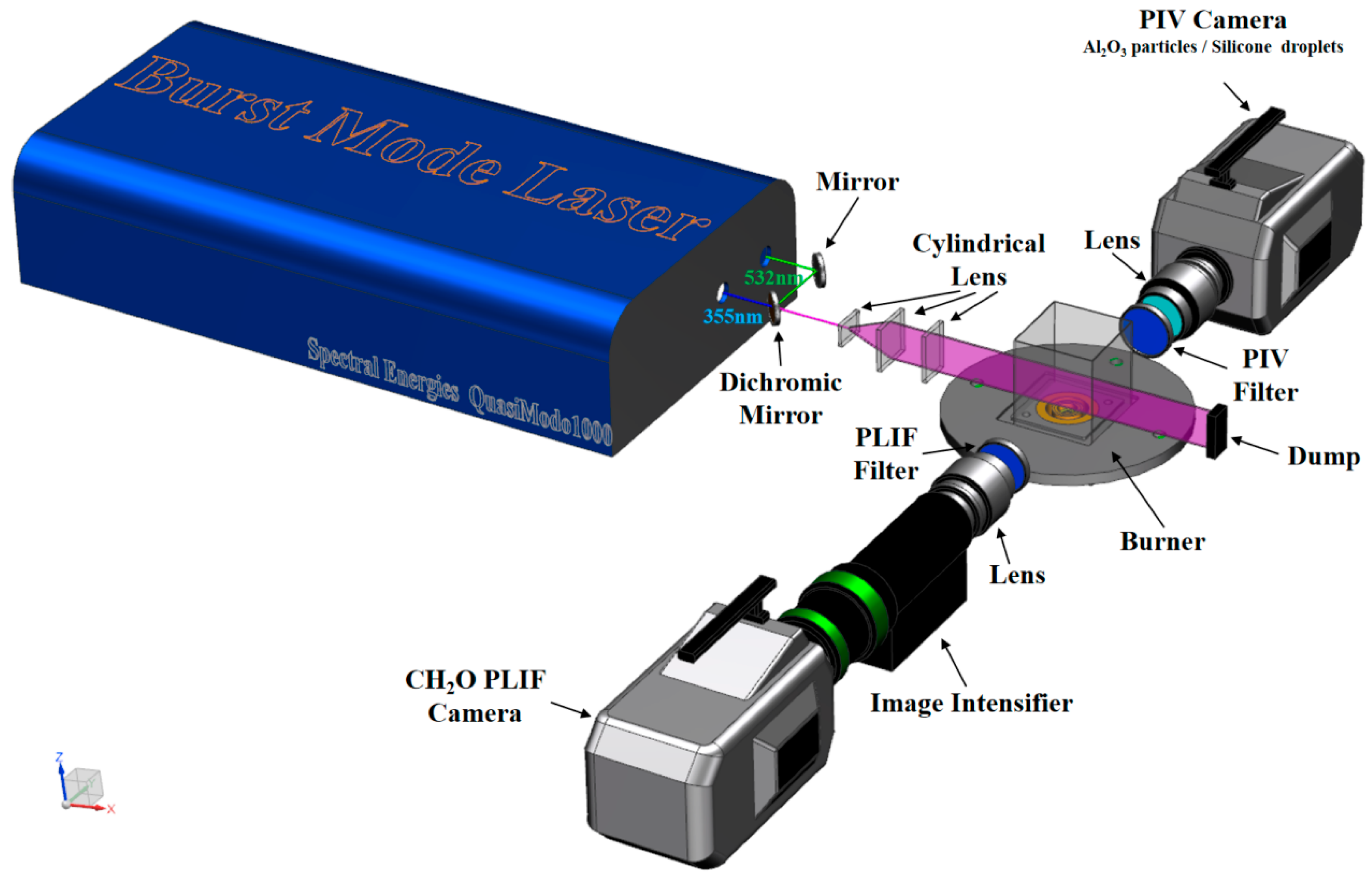
To resolve the rapid transient processes of flames and flow fields, simultaneous high-frequency CH2O-PLIF and PIV measurements are used in this experimental study, as shown in Figure 2. A burst-mode laser (Spectral Energies, Ohio, USA, Quasimodo 1000) simultaneously outputs 532 nm and 355 nm single pulses at a frequency of 20 kHz. The laser pulse energy of 532 nm is 40 mJ/pulse, and that of 355 nm reaches 180 mJ/pulse. The two laser beams are overlapped and expanded to form a 0.5 mm thick sheet passing through the center of the burner by a series of optics. The effective test height is 40 mm away from the dome outlet.
The 532 nm laser sheet is used to illuminate the particles for PIV measurements. Al2O3 tracer particles with a diameter of 1 μm are injected into the main stage and the pilot air. The Stokes number of the particles is about 3.22 × 10⁻³, and it can be considered that the particles have excellent following behaviors. The Mie scattering signal is captured by a high-speed CMOS camera (Phantom, New Jersey, USA, v2012) equipped with a Nikkor lens (Tokyo, Japan, 50 mm f/1.4 G) and a bandpass filter (Semrock, New York, USA, 520 nm). The exposure time of the high-speed camera is set to 1 μs, and the time interval between two images is 50 μs. The raw particle images are analyzed using PIVlab software v3.10 [32,33]. The spatial resolution is approximately 0.08 mm/pixel, and the interrogation window is set to 24 × 24 pixels with 50% overlap.
The 355 nm laser sheet is used for CH2O-PLIF test. CH2O is a marker of preheating zone and can be roughly regarded as the flame front of the premixed flame [34]. The CH2O fluorescence signal is captured by another Phantom v2012 camera equipped with a high-speed image intensifier (Lambert, Groningen, The Netherlands, HiCATT) and a Nikkor lens (50 mm f/1.4 G). In front of the lens, a multiband bandpass filter (Semrock, New York, USA, FF01–CH2O) is used to cover the CH2O fluorescence emission band over the 380–480 nm wavelength range. The exposure time of the high-speed camera is set to 1.0 μs, while the image intensifier is set to a gate time of 300 ns and a gain of 650 V.
The CH* chemiluminescence is captured separately by a high-speed CMOS camera equipped with an image intensifier and a bandpass filter (430 ± 5 nm). The exposure time of the high-speed camera is set to 10 μs, while the image intensifier is set to a gate time of 10 μs and a gain of 750 V. The distribution of the CH* signal indicates the position of flame front and the flame’s heat release rate (HRR). The data are recorded at a sampling frequency of 20 kHz for 0.5 s.

3. Result and Discussion

3.1. Average Flame Structures

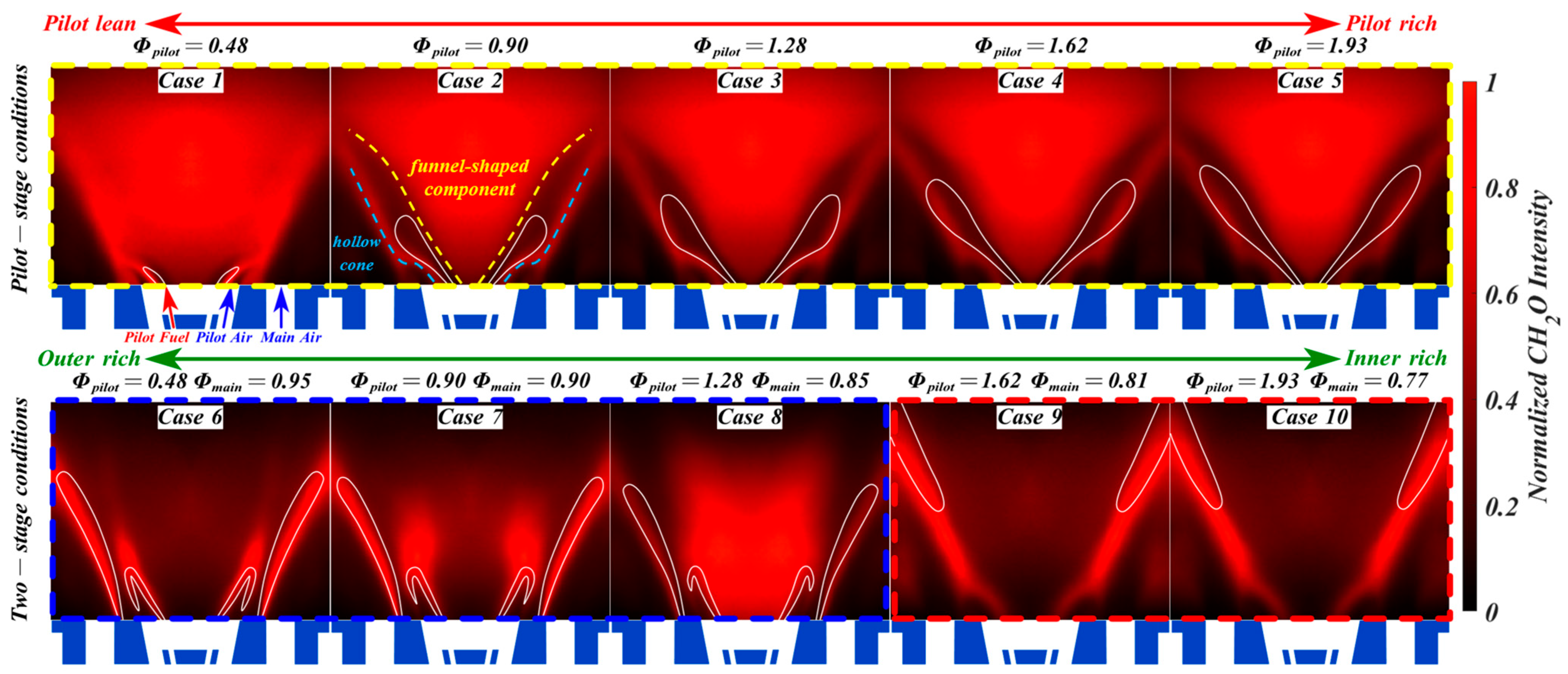
The time-averaged CH2O-PLIF distribution and the results of CH* Abel-inverse transformation are superimposed, as presented in Figure 3. The colored contour represents the CH2O signal, and the white lines represent the outer shape of the CH* Abel-inverse transformation results, which reflect the time-averaged flame structure. Cases 1 to 5 in the top row of the figure are the results of pilot-stage conditions, and the pilot fuel increases from left to right. Cases 6 to 10, in the bottom row of the figure, are the two-stage conditions; the main stage becomes leaner from left to right. It is noteworthy that for the two cases in the same column, the operating parameters of the pilot stage are exactly the same.
It can be observed that there are significant differences in the CH2O-PLIF distribution and flame structure under different conditions. Under the pilot-stage conditions, the CH2O-PLIF signal comprises two main components, as is marked as in Case 2 in Figure 3. One component, located in the center, is a solid funnel-shaped zone, with the bottom extending to the swirler outlet. The other component, outside the central funnel-shaped zone, is generally in the shape of a hollow cone. The two components are almost merged in Case 1. As the pilot fuel increases, the two components start to separate, ultimately achieving full separation as depicted in Case 5. The outer component has a turn just above the lip. At the turning point, the PLIF signal extends upstream to the outer edge of the lip in Case 1. As the pilot fuel increases, the PLIF signal at the lip gradually weakens and disappears in Cases 4 and 5. The CH* Abel-inverse transformation results show that the heat-release zone is on the outer side and marks the flame structure as V-shaped. There is no significant heat release in the central funnel-shaped zone. That is, the CH2O signals in the center are generated during the fuel preheating process.
Under the two-stage conditions, in Cases 6 to 8, the CH2O-PLIF of the two stages is spatially separated, as are the CH* Abel-inverse transformation results, and the flame is classified as an S-flame. The main flame is anchored to the inner side of main stage outlet and extends to the confinement boundary at a certain angle of divergence. The pilot flame is located inside the main flame and exhibits a sharp mountain-like shape, with an inner and outer flame. As the pilot stage becomes richer, the CH2O-PLIF signal in the center increases rapidly and finally fills the center, as depicted in Case 8. In Cases 9 and 10, the flame undergoes a dramatic change. Specifically, the CH2O-PLIF of the two stages merges into a single entity, with the CH2O-PLIF in the center vanishing as a result. The CH* Abel-inverse transformation results show the heat release zone is only located downstream. This indicates that the pilot fuel does not burn at the dome outlet but only undergoes a preheating reaction. This flame is denoted the L-flame.
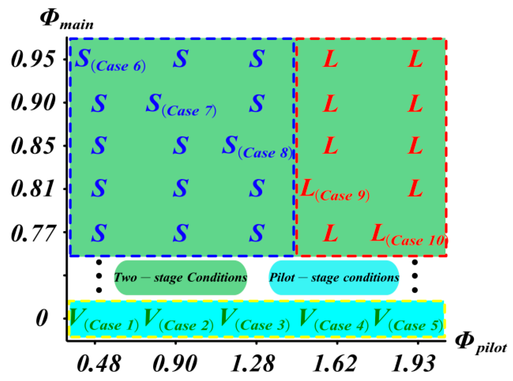
Extensive experimental tests on flame structure are carried out over a wide range of operating conditions, and the results are shown in Figure 4. Under the two-stage conditions, it becomes patently evident that the flame structure is governed by the pilot equivalence ratio, hardly bearing any correlation with the main stage. When the pilot equivalence ratio remains no more than 1.28, the flame assumes the S-flame. Conversely, once the pilot equivalence ratio attains 1.62 or higher, the flame transforms into an L-flame. The flame structure is primarily governed by the pilot equivalence ratio, exhibiting negligible dependence on the swirl SR and overall equivalence ratio, which differs from the results of a pilot operating in premixed mode as reported in [5,16,24]. Under the pilot operating in diffusion mode, the critical pilot equivalence ratio may vary across different burner configurations. However, this study emphasizes the existence of a critical transition threshold value. Thus, in a burner with diffusion flame at the pilot, the distribution characteristics of the fuel and its interaction with the flow field deserve in-depth attention.

3.2. Flow Field Characteristics

The average flow fields are shown with green vectors in Figure 5. Case 3, 8, and 9, representing the V-flame, S-flame, and L-flame, respectively, are selected for discussion. Velocity vectors are superimposed with the CH2O-PLIF contour (left side) and the vorticity contour (right side). The figure shows that in Case 3 and 9, the two-stage airflow forms an obvious confluence, while in Case 8, the two-stage airflow tends to flow independently. This shows some similarity to the characteristics of CH2O-PLIF. The airflow in the main stage seems to exhibit little difference among the three cases. The flow field structure is rather related to the flow angle of the pilot stage airflow. In Case 3 and Case 9, the pilot stage air has a large divergence angle, enabling it to converge with the main stage air quickly. In Case 8, the divergence angle is small, allowing the pilot stage air to flow downstream independently for a relatively long distance.
The magenta dotted line in the figure indicates the location where the axial velocity is zero, thereby reflecting the distribution of the recirculation zone. The primary recirculation zone (PRZ) in the center and the lip recirculation zone (LRZ) adjacent to the lip are observed in all three cases. Case 3 and 9 form a large PRZ, whose downstream is open. In Case 8, due to a large penetration depth and a small flow angle, the pilot stage air moves towards the center at a height of 30 mm. This truncates the recirculation zone, resulting in the formation of two distinct PRZs. The upper PRZ is open, while the lower PRZ is closed and mainly recirculates the pilot stage air.
Figure 5 also shows that there are four shear layers in the flow field, namely the pilot inner shear layer (PISL), the pilot outer shear layer (POSL), the main inner shear layer (MISL), and the main outer shear layer (MOSL). In Case 3 and 9, since the two stage air flows converge downstream, the PISL and MISL also merge downstream. However, in Case 8, the PISL and MISL are independent of each other. The POSLs in the three cases also differ significantly. Due to the relatively long penetration of the pilot stage air, the POSL of Case 8 is larger in size and extends a greater distance. Compared with CH2O-PLIF signals, it can clearly be seen that the pilot stage CH2O-PLIF mainly distributes in the PISL, and the main stage CH2O-PLIF mainly distributes in the MISL. The CH2O-PLIF of the two stages merges when the inner shear layers of the two stages’ air do, and it separates when the inner shear layers are separated.
The axial velocity distributions of the three cases are extracted as shown in Figure 6. At a height of 1 mm, there are two isolated velocity peaks on one side of the figure, representing the air jets of the pilot stage and main stage, respectively. At a height of 5 mm in Case 9, there is only one velocity peak, indicating that the two stage airflows have merged. In Case 3, at the height of 5 mm, the velocity peak of the pilot stage air rapidly merges with that of the main stage air, and by a height of 9 mm, they merge into one peak. In Case 8, the velocity peaks of the two stages’ air can still be distinguished even at a height of 9 mm. The evolution of the axial velocity distribution confirms the previously described flow characteristics of the two stage airflows.
It is worth noting that the peak axial velocity of the main stage under two-stage conditions is greater than that under pilot-stage conditions. This is because, under two-stage conditions, the main flame releases heat, reducing the local density and thereby increasing the flow velocity. Moreover, the peak velocity of the main stage in Case 8 is greater than that in Case 9. Therefore, it is speculated that the heat release of the main flame under the S-flame is more intense than that of the L-flame.
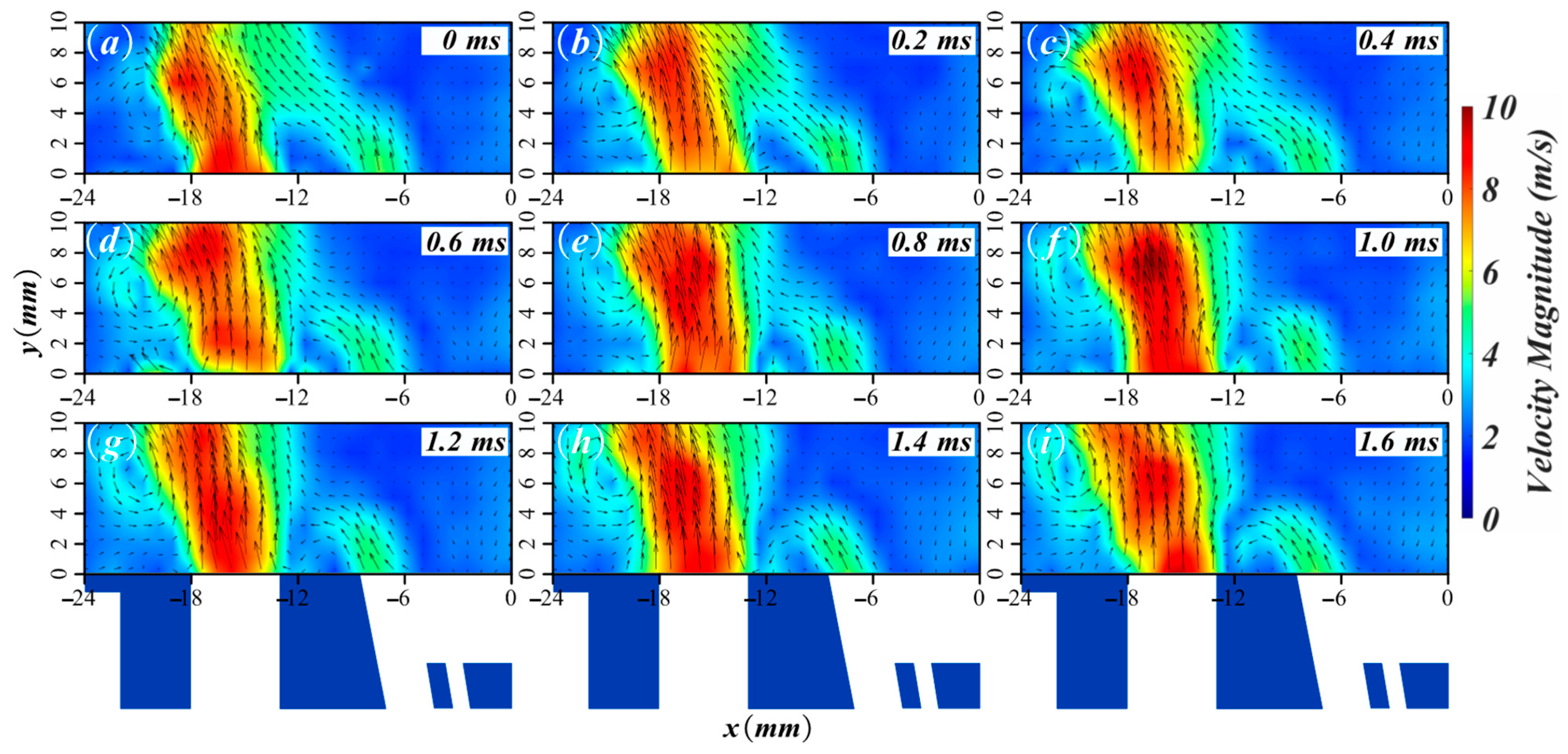
The time-averaged flow field results presented above demonstrate significant variations near the pilot stage in different cases. These flow characteristics are likely associated with the transition in centrally staged flame structures. This provides the primary motivation for conducting dedicated investigations on pilot-stage conditions (Case 1 to 5) in this study. Therefore, the transient flow dynamics near the pilot stage are examined in detail. The instantaneous velocity field at the swirler outlet of Case 3 is shown in Figure 7. It can be seen that the flow of the main stage is relatively stable, while the flow of the pilot stage varies significantly. Starting from 0 ms, due to reasons such as instantaneous flow rate fluctuations, the penetration depth of the pilot stage air gradually decreases, accompanied by an increase in the flow divergence angle. Under the synergy of the LRZ, a small part of the pilot stage air begins to flow towards the lip. At 1.4 ms, the majority of the pilot stage air directly rushes towards the lip, creating a large amount of reverse flow above it. This radial oscillatory phenomenon of pilot air is quite common under pilot-stage conditions. The behavior of pilot air inevitably influences the dispersion characteristics of the inner pilot fuel. Consequently, we subsequently investigate the diffusion characteristics of pilot fuel.

3.3. Pilot Fuel Transportation

Undoubtedly, the flow regime and oscillation behavior of pilot air will affect the transportation of pilot fuel and radicals. To investigate the effect of this influence, a silicone seeder is added to the pilot fuel pipe to inject fully atomized silicone droplets into the slot nozzle. The silicone droplets are ejected from the annular slot along with the pilot fuel. To ensure the silicone droplets exhibit excellent following behavior with respect to the pilot fuel, the silicone seeder is optimized to enable the droplet diameter to be less than 0.1 μm. Due to its relatively small total amount, the addition of silicone will not change the flame characteristics significantly. The silicone droplets are illuminated by a 532 nm light sheet at a frequency of 10 kHz. By capturing the Mie scattering signal of the droplets, the transport path of the pilot fuel can be visualized.
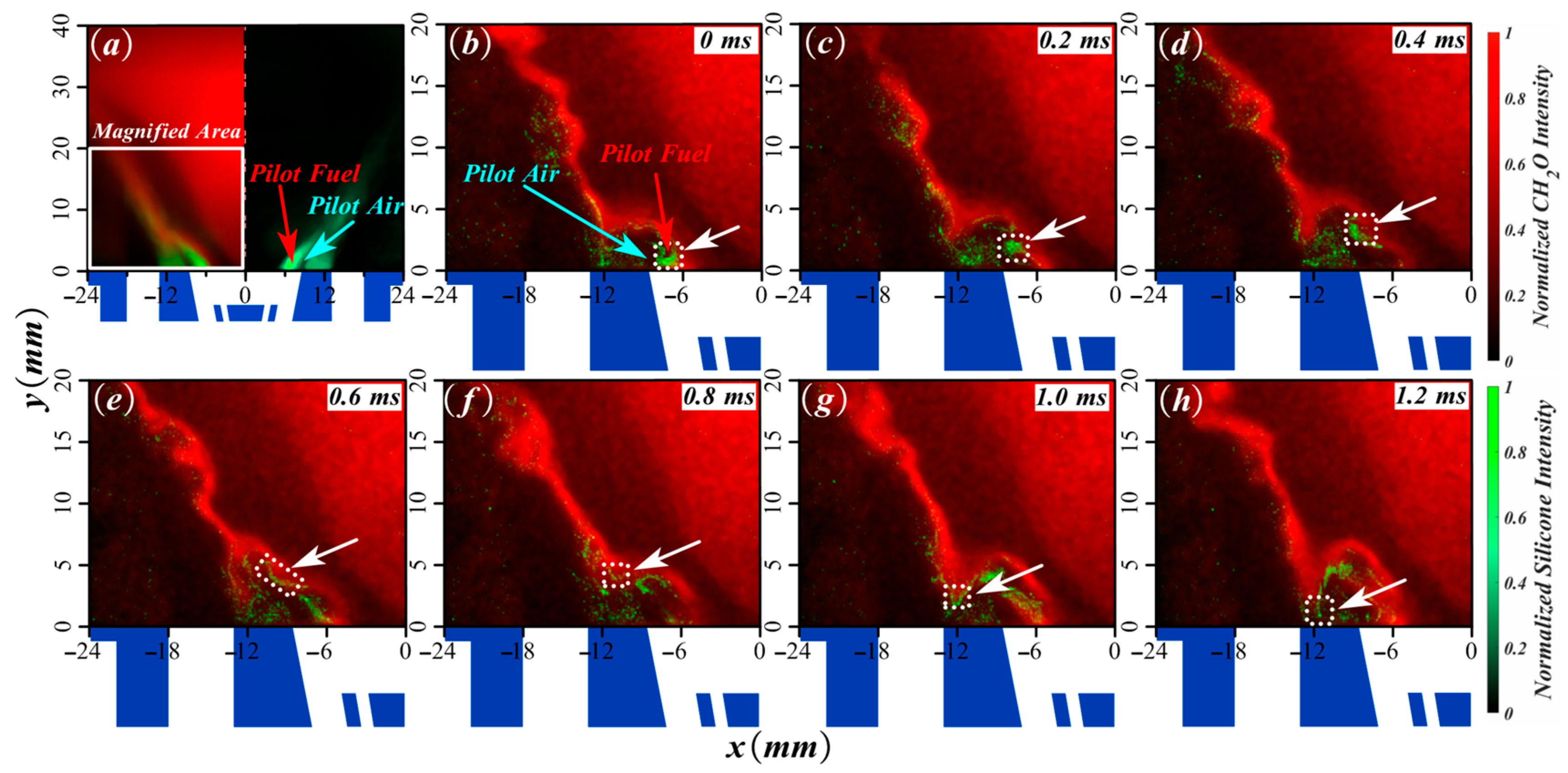
Silicone Mie scattering is tested simultaneously with CH2O-PLIF. Figure 8 shows the superposition of these two signals of Case 3. Here, the red contour indicates CH2O-PLIF and the green signal marks silicone. The averaged results in Figure 8a reveal that the silicone scattering signals (representing pilot fuel) are primarily concentrated on both the inner and outer sides of the pilot stage airflow. This implies that despite the pilot fuel being ejected from the inner side and facing hindrance from the pilot stage air, it can still reach the outer side of the pilot stage air.
The display of the evolution of the Mie signal in Figure 8b–h clearly demonstrates the transport process of the pilot fuel. A white dashed box is used to track the migration of a mass of fuel. Initially, the fuel propagates downstream on the inner side of the pilot stage airflow, as shown in Figure 8b–d. Subsequently, it is dispersed and transported to the outer side of the pilot stage air, as shown in Figure 8e,f. Finally, at an approximate height of y = 3 mm, this portion of pilot fuel is subsequently entrained to the inner side of main stage outlet, as shown in Figure 8g,h.
The transportation process proves that the pilot fuel is not directly transported to the inner side of the main stage outlet but rather seems to bypass along the pilot stage airflow. The initial downstream propagation of the pilot fuel is normal, but its following upstream propagation is surely not spontaneous. Combined with the instantaneous flow characteristics in Figure 7, it can be speculated that this might be caused by the frequent oscillation of the pilot stage airflow. When the pilot stage airflow rushes towards the LRZ in an instant, it can entrain the pilot fuel to reach the inner side of the main stage outlet. In addition, a fraction of the pilot fuel entrained in the LRZ interacts with the main stage air and continues to propagate downstream, as evidenced by scattered silicone signals observed along the inner side of the main stage airflow. This observation implies that an amount of pilot fuel cannot be combusted but is instead entrained and preheated into the PRZ. Ultimately, the central PRZ is characterized by being filled with CH2O-PLIF signals under pilot-stage conditions.
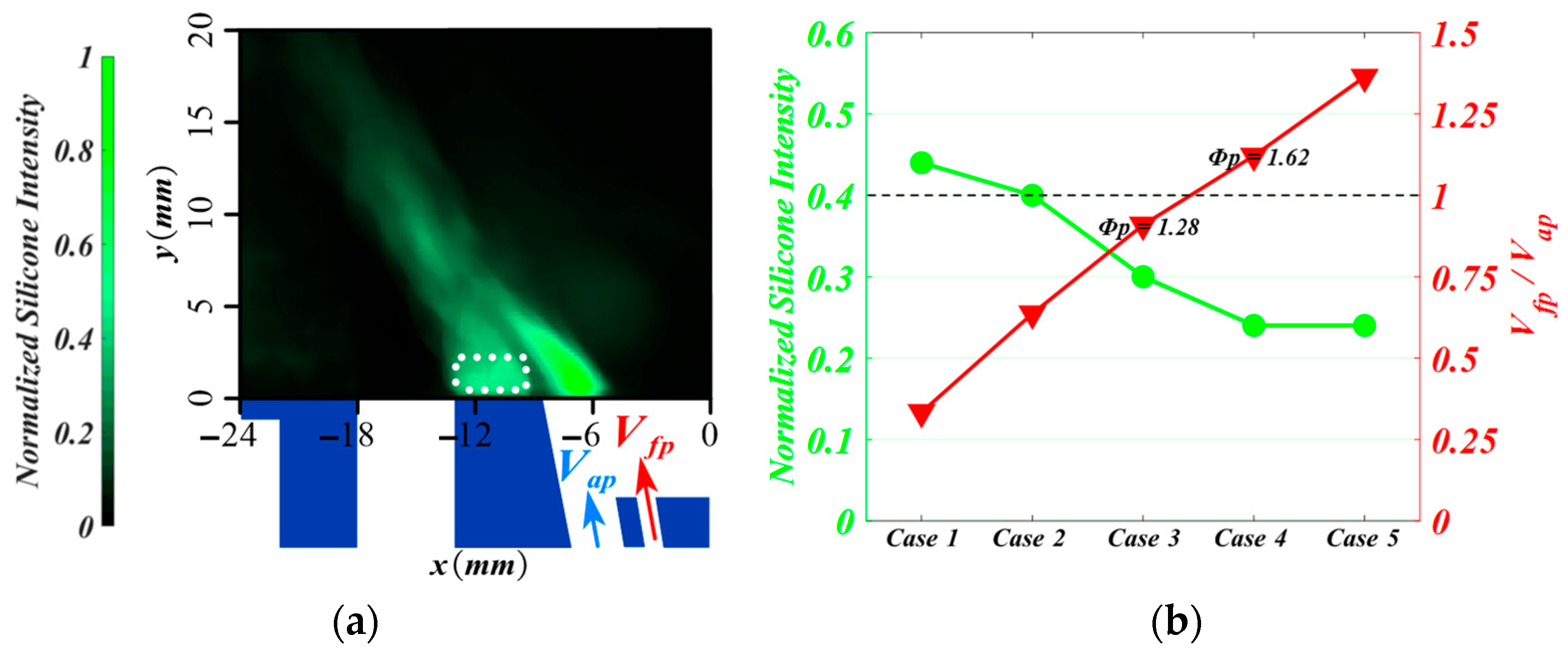
According to the common perception, as the pilot fuel increases, the local fuel concentration within the pilot stage rises, making it easier for the LRZ to accumulate fuel and reaction radicals. However, the actual situation is just the opposite. The intensity of the silicone signal at the LRZ is extracted and analyzed in Figure 9. The statistical area of the silicone signal is marked by the white dashed box in Figure 9a. From Case 1 to Case 5, as the pilot fuel increases, the concentration of silicone at the LRZ shows a significant downward trend in Figure 9b. Compared with Case 1, the concentration in Case 4 and Case 5 is decreased by nearly half. The average fuel injection velocity at the pilot annular slot nozzle exit is calculated. From Case 1 to Case 5, the fuel injection velocity (Vf_pliot) increases from 1.1 m/s to 4.5 m/s. The average axial velocity of the pilot stage air (Va_pliot) is approximately 3.3 m/s. We observe that when the pilot equivalence ratio approaches a critical transition threshold value between Case 3 and Case 4, the corresponding velocity ratio of pilot fuel to air (Vfp/Vap) approaches one. When Vfp < Vap, the pilot fuel and hot radicals are more susceptible to entrainment by the air flow, resulting in significant accumulation along the inner side of the main stage outlet. When Vfp > Vap, the pilot fuel with a relatively high velocity is less likely to be entrained by the oscillating pilot stage air and is more inclined to maintain its own flow trajectory. As a result, the concentration of silicone at the LRZ actually decreases.
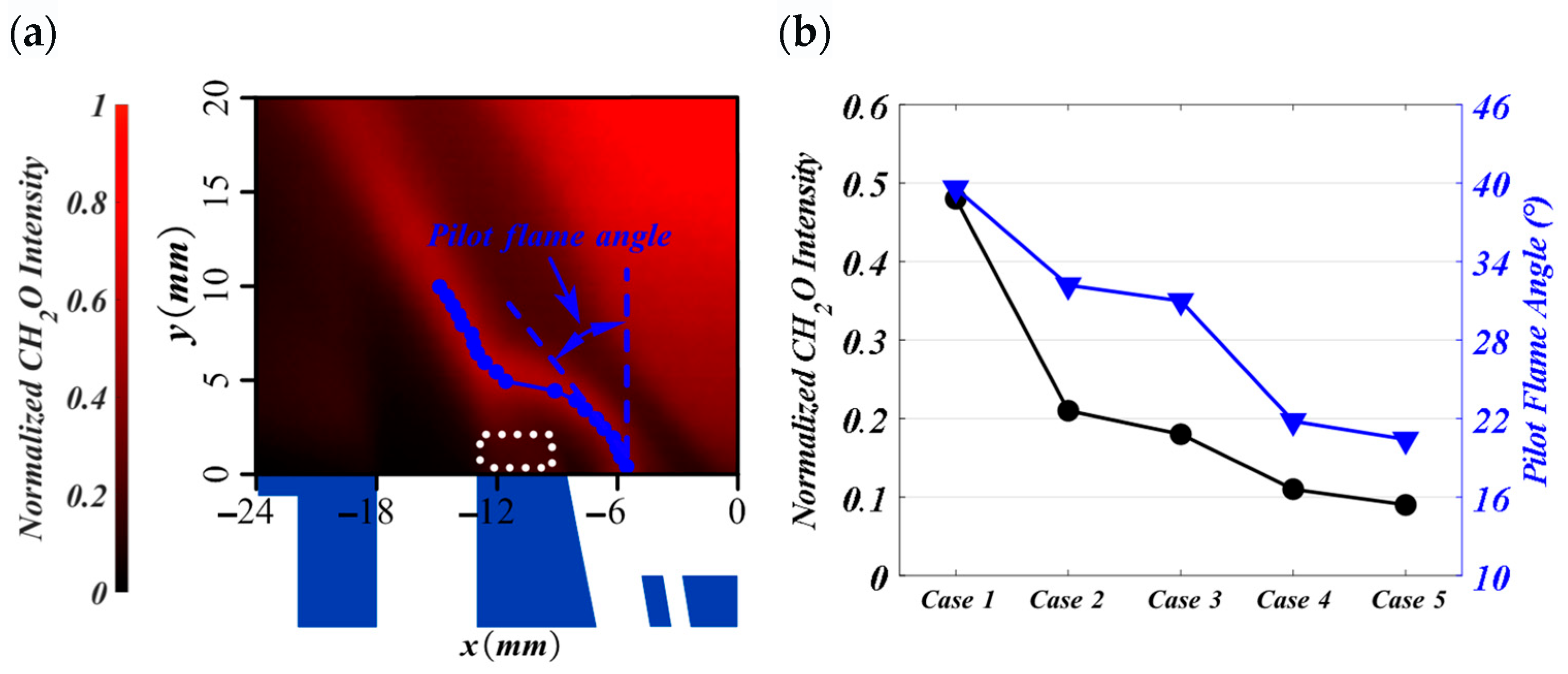
As the pilot fuel injected from the inner side of the pilot stage airflow can be transported outside, it can be speculated that the chemical radicals and heat of the pilot flame can also reach and accumulate in the inner side of main stage outlet in this way. The transportation of the reaction radicals and heat at the LRZ is similar to that of silicone. Figure 10 extracts the CH2O signal at the LRZ to confirm this. Predictably, as the pilot fuel increases, the CH2O concentration at the LRZ decreases rapidly. The blue circles in Figure 10a mark the maximum CH2O-PLIF signal, approximately representing the profile of the pilot flame front. An initial expansion angle of the pilot flame can be defined as the angle between the line connecting points of maximum CH2O-PLIF values at the pilot stage outlet and the vertical line.
As shown in Figure 10b, from Case 1 to Case 5, the pilot flame angle decreases from 39.6° to 20.4°, gradually approaching the injection semi-cone angle of the pilot annular slot nozzle. It should be noted that when the pilot equivalence ratio rises from 1.28 to 1.62, the pilot flame angle experiences a sudden decline. Meanwhile, under two-stage conditions, when the pilot-stage equivalence ratio undergoes the same change, the flame shape transforms abruptly from an S-shape to an L-shape. This illustrates that in the centrally staged burner with a diffusion pilot, the flame structure is highly correlated with pilot fuel injection.

3.4. Flame–Flow Interaction

In Cases 1, 2 and 3, due to the oscillation of the pilot stage airflow and the entrainment effect of LRZ, a large amount of reaction radicals and heat accumulate on the inner side of the main stage outlet. If a premixed mixture suitable for combustion is introduced into the main stage at this moment, the main stage can surely be ignited. This process occurs in Cases 6, 7, and 8. After the main stage is ignited, the intense heat release causes significant changes in the flame structure and flow field within the confinement. Concerning flame shape, it will transition from a V-flame to an S-flame, as shown in Figure 3. It is characterized by the attachment of the main flame at the main stage outlet and the emergence of a new flame outside the pilot stage air. Regarding flow characteristics, the two-stage airflow will shift from merged flow to separated flow. To gain a comprehensive understanding of the two distinct flame structures and flow regimes under the two-stage conditions, the interactions of flow, fuel, and flame necessitate further in-depth discussion.
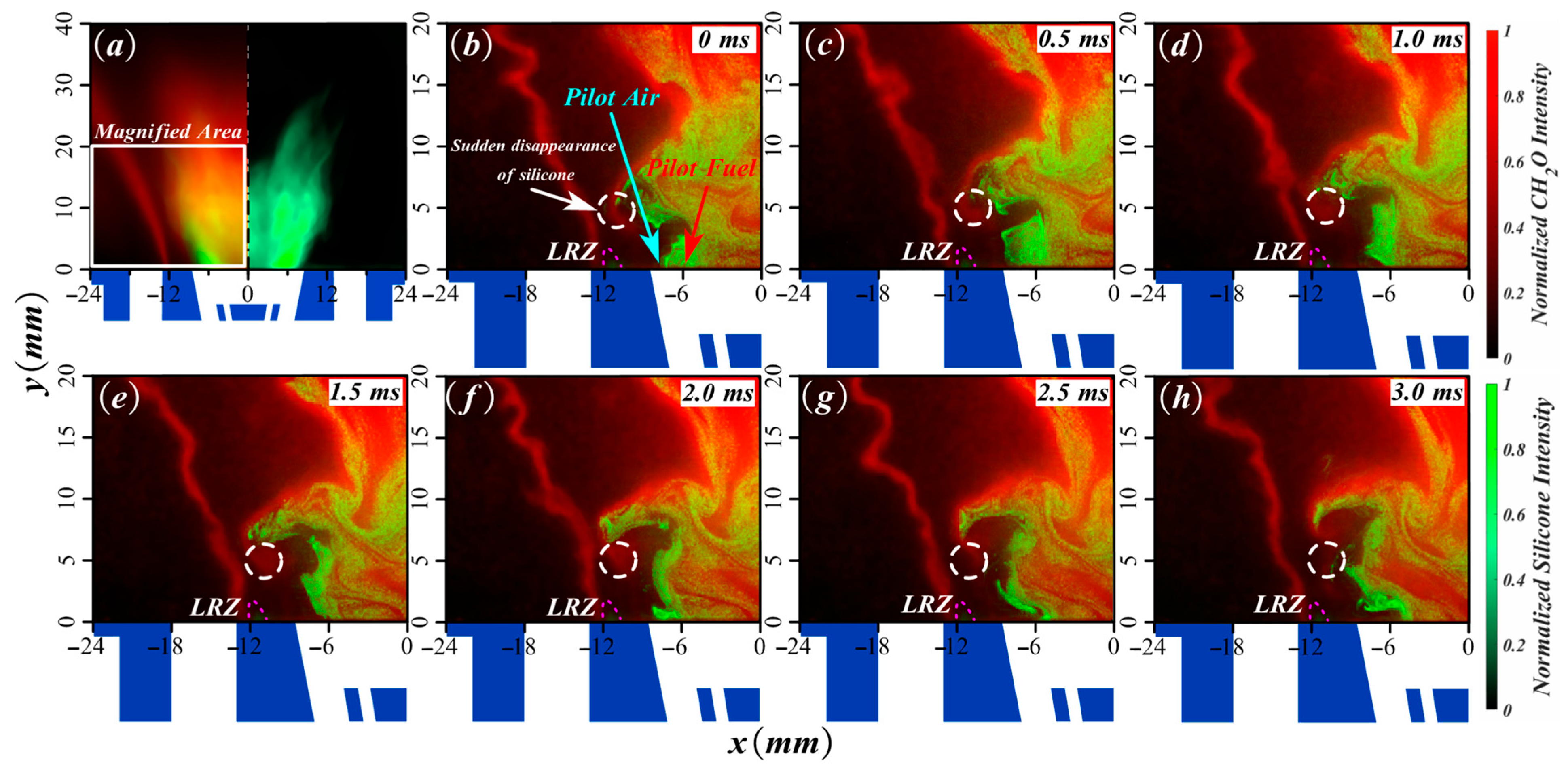
Figure 11 shows the superposition of CH2O-PLIF and silicone signals for Case 8. The time-averaged contour indicates that the silicone signal is strictly distributed at the center of the combustion chamber, which is significantly different from that under the pilot-stage conditions. The same phenomenon is also observed in Case 6 and Case 7. Figure 11b–h show that the silicone droplets can be transported downstream, cross over the top of the pilot stage air jet, and reach the outer side of the pilot stage airflow. However, the silicone droplets fail to be transported further to the main stage outlet. Instead, they disappear suddenly at a height of approximately 5 mm, as shown in the white dashed circle. Due to the presence of the outer pilot flame and its close proximity to the main flame at this location, the local temperature is extremely high, and the silicone here may have been rapidly burned off. This location is also adjacent to the LRZ. A reasonable speculation is that the LRZ would entrain the reaction radicals and heat here. Additionally, after the main flame is initially ignited at the main stage outlet, the LRZ can directly entrain the hot radicals from the main flame. Such processes enable the main stage outlet to have the ability to continuously ignite the premixed mixture of main stage. This could be the reason why the main flame can be stabilized at the main stage outlet.
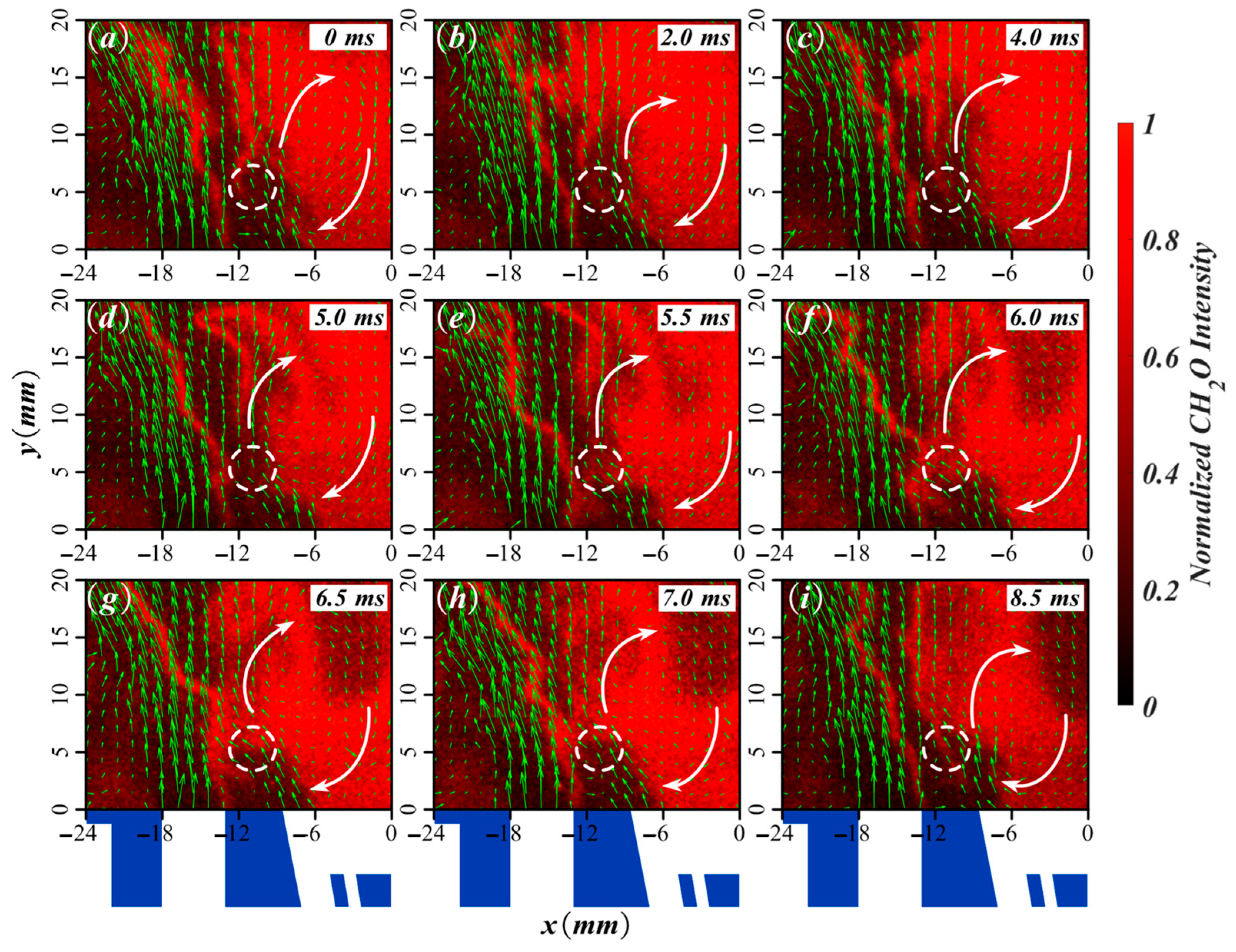
Figure 12 shows simultaneous CH2O-PLIF and velocity field evolution of Case 8. Despite the two stages typically showing characteristics of separated flow on average, the radial oscillation of the airflows causes the two-stage airflows to intersect briefly. For example, at 5.0 ms, the two stage airflows start to approach each other. By 6.0 ms, partial confluence occurs at a height of approximately 5 mm, as shown in the white dashed box in the figure. By 7.0 ms, the airflows begin to show a separated trend again, and by 8.5 ms, they are completely separated. When the two stage airflows start to approach at 5.0 ms, the two stage flames also start to become closer. At 6.0 ms, the two stage flames are completely connected. As the two stage airflows move apart at 8.5 ms, the two stage flames are also completely separated. This radial oscillation process supports the above-mentioned speculation that there is a high-temperature region above the LRZ. This high-temperature region consumes the fuel transported from the pilot stage. Since this high-temperature region is adjacent to the LRZ, it contributes to the stabilization of the root of the main flame at the main stage outlet.
A careful check of the velocity vectors in the PRZ reveals that, in most moments, the reaction radicals and heat from the pilot flame can recirculate to the outlet of the pilot stage, as indicated by the flow trajectories of the white arrows in the figure. This is crucial for the stabilization of the pilot flame, ensuring that stable combustion can be maintained at the root of the pilot flame.
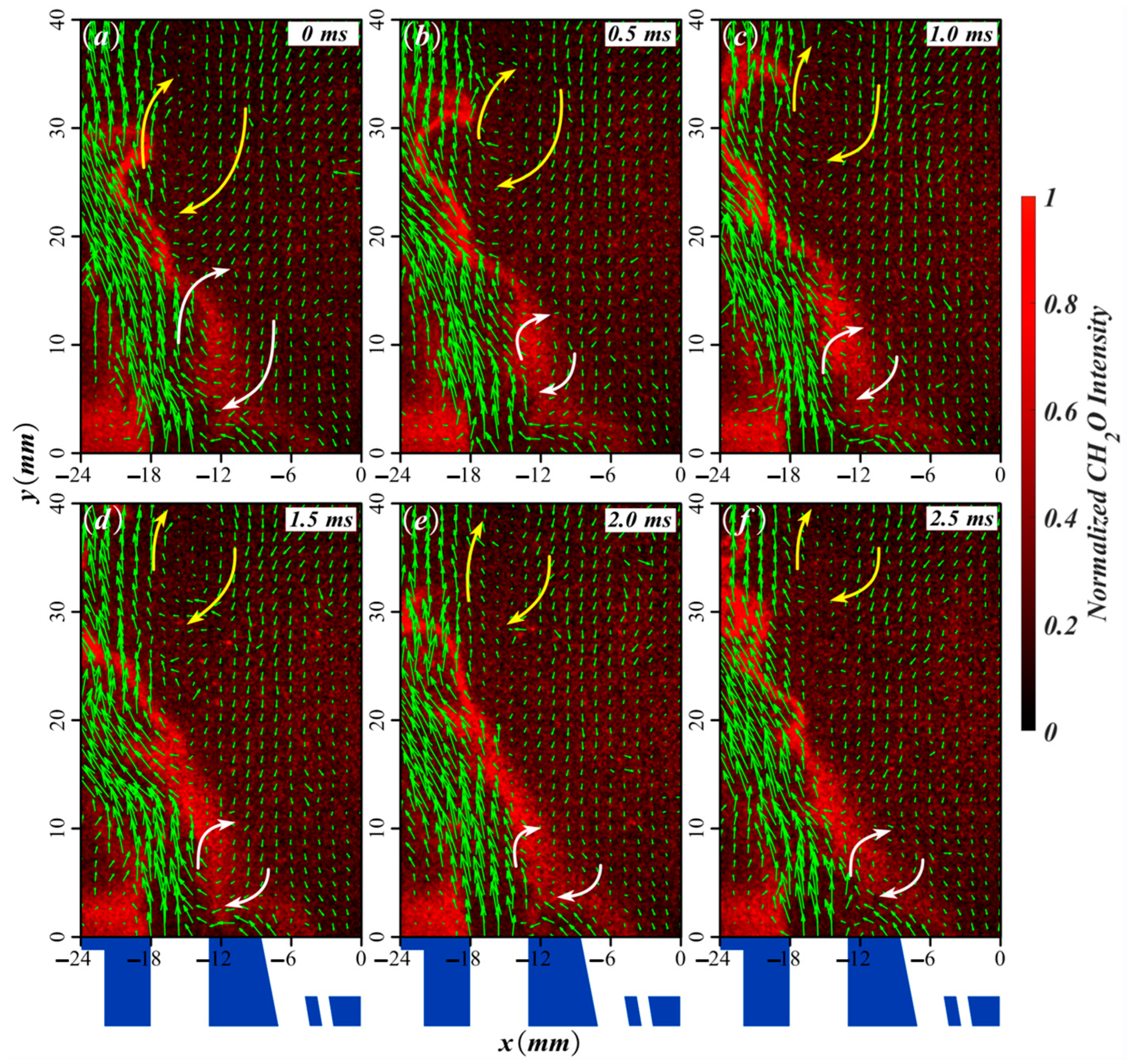
In Case 4, the reaction radicals and heat accumulated at the main stage outlet have been significantly reduced. As in Case 9, the fuel supplied to the primary combustion stage fails to be ignited directly at the main stage outlet. Instead, it is ignited only after intersecting with the pilot flame. This also occurs in Case 10. Figure 13 shows the simultaneous CH2O-PLIF and velocity field evolution of Case 9. It can be observed that at a height of about 30 mm, there is a relatively stable large-scale vortex inside the main stage airflow, as show in yellow arrows. This vortex is located too far downstream and may not contribute much to flame stabilization.
At a height of 5–10 mm, on the inner side where the two stage airflows intersect, there is a local vortex, as shown in white arrows. This vortex is at the intersection of the two stage formaldehyde signals. The high-temperature gas entrained from the main flame can ignite the root of the main flame at this location. Unfortunately, no direct high-temperature gas recirculation is detected at the outlet of the pilot stage. This may be the reason why the root of the pilot flame in the L-flame cannot be sustained. At the intersection of the two stages, the formaldehyde signal tends to propagate upstream but fails to reach the outlet of the main stage. This may be because the cold air from the pilot stage blows out the flame, preventing the main flame from further propagating towards the outlet of the main stage.

4. Conclusions

This work addresses a critical knowledge gap in centrally staged combustion by investigating a practically prevalent yet fundamentally underexplored configuration: the diffusion pilot flame. The key scientific contribution is the revelation of the pilot fuel–air velocity ratio (Vfp/Vap) as the governing mechanism for global flame structure transitions—a paradigm distinct from premixed pilot systems. Employing high-frequency CH2O-PLIF, CH* chemiluminescence, PIV, and innovative fuel-tracing techniques, we have delineated the underlying processes. The main conclusions are as follows.
(1)
Under two-stage conditions, the flame structure is primarily governed by the pilot equivalence ratio, leading to the identification of two distinct modes: the stratified flame (S-flame) and the lifted flame (L-flame). This contrasts with premixed pilot systems and underscores the unique sensitivity of diffusion pilots to fuel–flow interactions.
(2)
The S-flame corresponds to the separated flow of the two stages, whereas the L-flame corresponds to the merged flow of the two stages. The pilot stage CH2O-PLIF mainly distributes in the PISL, and the main stage CH2O-PLIF mainly distributes in the MISL. The CH2O-PLIF of the two stages merges when the inner shear layers of the two stage air do, and it separates when the inner shear layers are separated. Significant radial oscillation of the pilot stage airflow is identified as a key dynamic feature.
(3)
The pilot fuel, despite being injected internally, is effectively transported to the outer side of the pilot air. With a low pilot fuel supply (Vfp/Vap < 1), flow oscillations entrain fuel and hot radicals towards the LRZ, accumulating them at the inner side of the main stage outlet. This accumulation provides a continuous ignition source, enabling the main premixed mixture to stabilize as a rooted S-flame.
(4)
At a higher pilot equivalence ratio (Vfp/Vap > 1), the reduced entrainment of pilot fuel and radicals prevents ignition at the main stage outlet. Consequently, the main stage mixture is ignited downstream upon intersecting with the pilot flame, forming an L-flame. Simultaneous measurements reveal that in this L-mode, hot products cannot recirculate to the pilot stage root, leading to its eventual extinction.
(5)
This study clarifies the governing role of the pilot equivalence ratio and the associated fuel–air velocity ratio in the transition between the S-flame and L-flame modes. For practical combustor design, this underscores the critical importance of precisely controlling the pilot fuel injection characteristics. Achieving the desired S-flame for stable operation requires careful management of the pilot fuel–air interaction to ensure adequate entrainment of fuel and radicals to the main stage outlet, avoiding unintended transitions to the L-flame mode with potential stability concerns.

Author Contributions

W.M.: data curation, investigation, methodology, software, writing—original draft, visualization. T.L.: data curation, investigation, methodology. B.W.: conception, methodology, investigation, writing—original draft, review and editing, project administration, funding acquisition. G.R.: resources, supervision. X.G.: resources, supervision. All authors have read and agreed to the published version of the manuscript.

Funding

This research was funded by the National Science and Technology Major Project of China (Grant No. J2019-III-0002-0045) and the National Natural Science Foundation of China (Grant No. 52106158, Grand No. 92041001).

Data Availability Statement

The data that support the findings of this study are available from the corresponding author upon reasonable request, since the data are not publicly available due to privacy restrictions.

Conflicts of Interest

The authors declare that they have no known competing financial interests or personal relationships that could have appeared to influence the work reported in this paper.

References

  1. Correa, S.M. Power generation and aero-propulsion gas turbines: From combustion science to combustion technology. In Symposium (International) on Combustion; Elsevier: Amsterdam, The Netherlands, 1998; Volume 27, pp. 1793–1807. [Google Scholar]
  2. Mongia, H.C. TAPS–A 4th generation propulsion combustor technology for low emissions. In Proceedings of the AIAA/ICAS International Air and Space Symposium and Exposition: The Next 100 Years, AIAA 2003–2657, Dayton, OH, USA, 14–17 July 2003. [Google Scholar]
  3. Lazlk, W.; Doerr, T.; Bake, S.V.; Vd Bank, R.; Rackwitz, L. Development of Lean-Burn low-NOx combustion technology at Rolls-Royce Deutschland. In Proceedings of the ASME Turbo Expo 2008: Power for Land, Sea, and Air, Berlin, Germany, 9–13 June 2008; Amer Soc Mechanical Engineers: New York, NY, USA, 2008; Volume 3, pp. 797–807. [Google Scholar]
  4. Wang, B.; Zhang, C.; Lin, Y.Z.; Zhang, C.; Lin, Y.; Hui, X.; Li, J. Influence of the main swirler vane angle on the ignition performance of TELSESSI combustor. J. Eng. Gas Turbines Power 2017, 139, 011501. [Google Scholar] [CrossRef]
  5. Han, X.; Laera, D.; Morgans, A.S.; Lin, Y.; Sung, C.-J. The effect of stratification ratio on the macroscale structure of stratified swirling flames: Experimental and numerical study. J. Eng. Gas Turbines Power 2018, 140, 121004. [Google Scholar] [CrossRef]
  6. Guiberti, T.F.; Durox, D.; Zimmer, L.; Schuller, T. Analysis of topology transitions of swirl flames interacting with the combustor side wall. Combust. Flame 2015, 162, 4342–4357. [Google Scholar] [CrossRef]
  7. Carneiro Piton, L.; Senra Pessanha Rios Nobrega, G.; Figueira da Silva, L.F.; Scouflaire, P.; Darabiha, N. Experimental study of the influence of the swirl number on lean premixed combustion regimes. J. Braz. Soc. Mech. Sci. Eng. 2020, 42, 210. [Google Scholar] [CrossRef]
  8. Mercier, R.; Guiberti, T.; Chatelier, A.; Durox, D.; Gicquel, O.; Darabiha, N.; Schuller, T.; Fiorina, B. Experimental and numerical investigation of the influence of thermal boundary conditions on premixed swirling flame stabilization. Combust. Flame 2016, 171, 42–58. [Google Scholar] [CrossRef]
  9. Shanbhogue, S.J.; Sanusi, Y.; Taamallah, S.; Habib, M.; Mokheimer, E.; Ghoniem, A. Flame macrostructures, combustion instability and extinction strain scaling in swirl-stabilized premixed CH4/H2 combustion. Combust. Flame 2016, 163, 494–507. [Google Scholar] [CrossRef]
  10. Candel, S.; Durox, D.; Schuller, T.; Bourgouin, J.-F.; Moeck, J.P. Dynamics of swirling flames. Annu. Rev. Fluid Mech. 2014, 46, 147–173. [Google Scholar] [CrossRef]
  11. Han, X.; Laera, D.; Morgans, A.; Sung, C.; Hui, X.; Lin, Y. Flame macrostructures and thermoacoustic instabilities in stratified swirling flames. Proceedings of the ASME Turbo Expo 2012, Copenhagen, Denmark. 2012. Proc. Combust. Inst. 2019, 37, 5377–5384. [Google Scholar] [CrossRef]
  12. Song, H.; Lin, Y.; Han, X.; Yang, D.; Zhang, C.; Sung, C.-J. The thermoacoustic instability in a stratified swirl burner and its passive control by using a slope confinement. Energy 2020, 195, 116956. [Google Scholar] [CrossRef]
  13. Kim, K.T.; Hochgreb, S. The nonlinear heat release response of stratified lean-premixed flames to acoustic velocity oscillations. Combust. Flame 2011, 158, 2482–2499. [Google Scholar] [CrossRef]
  14. Wang, X.; Han, X.; Wang, J.; Du, J.; Sung, C.-J. Flame stabilization and thermoacoustic instability during operating condition modulations: Roles of pilot and main flames. Phys. Fluids 2022, 34, 125102. [Google Scholar] [CrossRef]
  15. Sweeney, M.S.; Hochgreb, S.; Dunn, M.J.; Barlow, R.S. The structure of turbulent stratified and premixed methane/air flames II: Swirling flows. Combust. Flame 2012, 159, 2912–2929. [Google Scholar] [CrossRef]
  16. Han, M.; Han, X.; Wang, J.; Zhang, C.; Tian, L. Effect of confinement size on flame macrostructures and thermoacoustic instability in a centrally-staged burner. Appl. Therm. Eng. 2025, 279, 127720. [Google Scholar] [CrossRef]
  17. Zhang, Z.; Liu, X.; Gong, Y.; Yang, Y.; Tang, Z.; Liu, G.; Deng, F.; Yang, J.; Zheng, H. Experimental study of stratified swirl flame dynamics in a model gas turbine combustor. Energy 2020, 211, 118699. [Google Scholar] [CrossRef]
  18. Han, X.; Yang, D.; Wang, J.; Zhang, C. The effect of inlet boundaries on combustion instability in a pressure-elevated combustor. Aerosp. Sci. Technol. 2021, 111, 106517. [Google Scholar] [CrossRef]
  19. Boxx, I.; Slabaugh, C.; Kutne, P.; Lucht, R.; Meier, W. 3 kHz PIV/OH-PLIF measurements in a gas turbine combustor at elevated pressure. Proc. Combust. Inst. 2015, 35, 3793–3802. [Google Scholar] [CrossRef]
  20. Li, L.; Lin, Y.; Fu, Z.; Zhang, C. Emission characteristics of a model combustor for aero gas turbine application. Exp. Therm. Fluid Sci. 2016, 72, 235–248. [Google Scholar] [CrossRef]
  21. Chong, C.T.; Lam, S.S.; Hochgreb, S. Effect of mixture flow stratification on premixed flame structure and emissions under counter-rotating swirl burner configuration. Appl. Therm. Eng. 2016, 105, 905–912. [Google Scholar] [CrossRef]
  22. Han, X.; Laera, D.; Yang, D.; Zhang, C.; Wang, J.; Hui, X.; Lin, Y.; Morgans, A.S.; Sung, C.-J. Flame interactions in a stratified swirl burner: Flame stabilization, combustion instabilities and beating oscillations. Combust. Flame 2020, 212, 500–509. [Google Scholar] [CrossRef]
  23. Wang, S.; Liu, X.; Li, L.; Han, X.; Zhang, C.; Qi, F. Effects of stratification ratio on flame stabilization and flow structure in stratified swirling flame. Acta Aerodyn. Sin. 2020, 38, 619–628. [Google Scholar]
  24. Xiang, J.; Li, J.; Mo, W.; Wang, B.; Yang, D.; Gan, X. The flame macrostructure and thermoacoustic instability in a centrally staged burner operating in different pilot stage equivalence ratios. Phys. Fluids 2024, 36, 075149. [Google Scholar] [CrossRef]
  25. Fu, P.; Li, S.; Hou, L.; Wen, Q.; Li, J.; Ma, H. Flame structure transition and instability excitation by pilot fuel in a centrally staged combustor. Phys. Fluids 2025, 37, 015138. [Google Scholar] [CrossRef]
  26. Fu, P.; Wen, Q.; Hou, L.; Li, J.; Ma, H. Interaction among flame structures and thermoacoustic instabilities in a centrally staged combustor. Appl. Therm. Eng. 2024, 254, 123862. [Google Scholar] [CrossRef]
  27. Law, C.K. Combustion Physics; Cambridge University Press: Cambridge, UK, 2006. [Google Scholar]
  28. Cavaliere, D.E.; Kariuki, J.; Mastorakos, E. A Comparison of the Blow-Off Behaviour of Swirl-Stabilized Premixed, Non-Premixed and Spray Flames. Flow Turbul. Combust. 2013, 91, 347–372. [Google Scholar] [CrossRef]
  29. Dhanuka, S.K.; Temme, J.E.; Driscoll, J.F. Unsteady Aspects of Lean Premixed Prevaporized Gas Turbine Combustors: Flame-Flame Interactions. J. Propuls. Power 2011, 27, 631–641. [Google Scholar] [CrossRef]
  30. Dhanuka, S.K.; Temme, J.E.; Driscoll, J.F.; Mongia, H.C. Vortex-shedding and mixing layer effects on periodic flashback in a lean premixed prevaporized gas turbine combustor. Proc. Combust. Inst. 2009, 32, 2901–2908. [Google Scholar] [CrossRef]
  31. Temme, J.E.; Allison, P.M.; Driscoll, J.F. Combustion instability of a lean premixed prevaporized gas turbine combustor studied using phase-averaged PIV. Combust. Flame 2014, 161, 958–970. [Google Scholar] [CrossRef]
  32. Thielicke, W.; Sonntag, R. Particle image velocimetry for MATLAB: Accuracy and enhanced algorithms in PIVlab. J. Open Res. Softw. 2021, 9, 12. [Google Scholar] [CrossRef]
  33. Thielicke, W.; Stamhuis, E.J. PIVlab-Towards user-friendly, affordable and accurate digital particle image velocimetry in MATLAB. J. Open Res. Softw. 2014, 2, e30. [Google Scholar] [CrossRef]
  34. Wang, S.; Zheng, J.; Xu, L.; An, Q.; Han, X.; Zhang, C.; Li, L.; Xia, X.; Qi, F. Experimental investigation of the helical mode in a stratified swirling flame. Combust. Flame 2022, 244, 112268. [Google Scholar] [CrossRef]
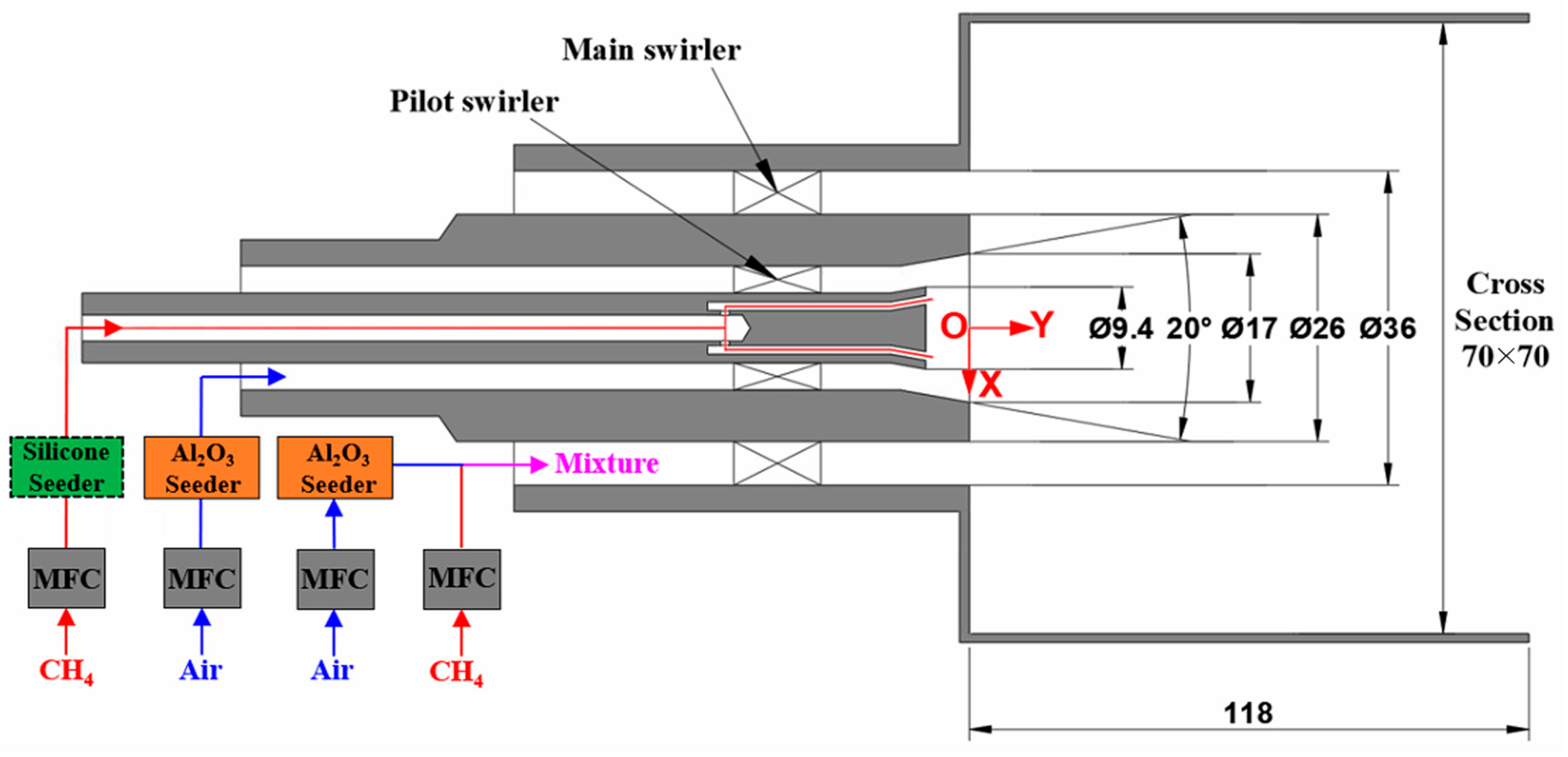
Figure 1. Schematic of the centrally staged burner (not scaled; dimensions in millimeters).
Aerospace 12 01019 g001
Figure 2. Schematic of simultaneous high-frequency optical setup.
Aerospace 12 01019 g002
Figure 3. Time-averaged CH2O-PLIF (colored contour) superimposed with CH* Abel-inverse transformation results (white lines).
Aerospace 12 01019 g003
Figure 4. Flame structure under different equivalence ratios of the two stages.
Aerospace 12 01019 g004
Figure 5. Time-averaged flow vectors overlapped with CH2O-PLIF and vorticity: (a) Case 3; (b) Case 8; (c) Case 9.
Aerospace 12 01019 g005
Figure 6. Time-averaged axial velocity profiles at various heights: (a) y = 1 mm; (b) y = 5 mm; (c) y = 9 mm.
Aerospace 12 01019 g006
Figure 7. The instantaneous flow field at the dome outlet of Case 3.
Aerospace 12 01019 g007
Figure 8. Silicone signal superimposed with the CH2O-PLIF of Case 3: (a) averaged contour; (bh) time sequence of simultaneous distribution.
Aerospace 12 01019 g008
Figure 9. Statistics of silicone signal intensity at the LRZ: (a) Schematic of the statistical position; (b) Statistical values.
Aerospace 12 01019 g009
Figure 10. Statistics of CH2O intensity at the lip and pilot flame angle: (a) schematic of statistical position; (b) statistical values.
Aerospace 12 01019 g010
Figure 11. Silicone signal superimposed with the CH2O-PLIF of Case 8: (a) averaged contour; (bh) time sequence of simultaneous distribution.
Aerospace 12 01019 g011
Figure 12. Simultaneous CH2O-PLIF and velocity field evolution of Case 8.
Aerospace 12 01019 g012
Figure 13. Simultaneous CH2O-PLIF and velocity field evolution of Case 9.
Aerospace 12 01019 g013
Table 1. Operating conditions.
CaseConditionΦtotalΦpΦmSR
1Pilot-stage conditions0.0530.480-
20.10.90
30.1421.28
40.191.62
50.2141.93
6Two-stage conditions0.90.480.950.5
70.900.901.0
81.280.851.5
91.620.812.0
101.930.772.5
Disclaimer/Publisher’s Note: The statements, opinions and data contained in all publications are solely those of the individual author(s) and contributor(s) and not of MDPI and/or the editor(s). MDPI and/or the editor(s) disclaim responsibility for any injury to people or property resulting from any ideas, methods, instructions or products referred to in the content.