Article

Investigation of the Overall Damage Assessment Method Used for Unmanned Aerial Vehicles Subjected to Blast Waves

1
Institute of Systems Engineering, China Academy of Engineering Physics, Mianyang 621999, China
2
School of Civil Engineering and Architecture, Southwest University of Science and Technology, Mianyang 621000, China
3
Nanjing Opatiya Information Technology Co., Ltd., Nanjing 211100, China
*
Author to whom correspondence should be addressed.
Aerospace 2024, 11(8), 651; https://doi.org/10.3390/aerospace11080651
Submission received: 2 July 2024 / Revised: 7 August 2024 / Accepted: 8 August 2024 / Published: 10 August 2024

Abstract

:
With the aim of investigating the assessment methodology for the overall damage effects on an unmanned aerial vehicle (UAV) subjected to a blast wave, the failure criteria for the typical UAV was formulated through an analysis of the structural strength design standards. Specifically, the shear force associated with wing failure can serve as a critical parameter for assessing the overall damage inflicted on the UAV by blast waves. According to the design load criterion of the aircraft, the shear force value corresponding to the overall failure of the typical UAV was calculated. Numerical simulations were conducted to investigate the mechanical response of UAV structures under blast wave loading generated by a 500 g explosive. Combining the critical shear force values obtained from theoretical calculations with the numerical simulation results, two distances between the explosives and the UAV that could produce different damage effects were estimated, namely 1 m and 2.5 m. Subsequently, static explosion experiments with equivalent explosive charges were performed, revealing different damage effects on a typical UAV at two specific distances. The numerical simulation results were highly consistent with the experimental observations, further validating the scientific and rational basis for using shear force as a primary parameter in assessing overall structural damage to fixed-wing UAVs.

1. Introduction

In the era of rapidly evolving technology, UAV (Unmanned Aerial Vehicle) technology has emerged as a revolutionary breakthrough, advancing at an unprecedented pace globally. Characterized by their high flexibility, low cost, advanced intelligence, and versatility, UAVs have found widespread applications in numerous engineering and scientific research fields. In the realm of modern aviation technology research, assessing the damage to UAVs subjected to explosive shock effects has become a pivotal research topic.
According to varying types of threat terminal products, the damage elements of air defense warheads on aircraft targets usually contains fragments (including conventional fragments, projectiles, discrete rods, etc.) and shock waves [1,2,3]. Due to their distinct characteristics, fragment damage and shockwave damage can be regarded as two independent modes of destruction in the field of aircraft damage research to some extent [2,4]. High-speed fragments penetrating into aircraft targets is considered to be the principal damage mode of air defense weapons, which is widely studied [5,6,7]. Shock wave overpressure attenuates rapidly with the increase in distance, especially for large target-missing quantity air defense warheads, which are commonly regarded as secondary threats for damage assessments [2,8]. Along with the flying development of precision guidance technology, the target-missing quantity of air defense warheads has decreased greatly; therefore, the shock wave has gradually become the major damage element for UAV targets.
Establishing a comprehensive damage model for the entire aircraft is complex and entails a substantial workload. To simultaneously meet the requirements of convenience and accuracy for engineering applications, targeted studies should be conducted focusing on critical components or vulnerable parts of the aircraft structure. The adverse effects of explosive shock waves on wing, tail, and canard structures, among other airfoil components, can significantly impair the performance of an aircraft. Intense plastic deformation can alter the aerodynamic shape of the aircraft, leading to increased drag, insufficient lift, and the reduced efficiency of surface controls, thereby potentially resulting in catastrophic consequences, including the possibility of aircraft crash [9,10,11]. Therefore, the analysis of wing damage can be prioritized in the damage assessment of UAV targets.
In the existing battle damage assessment operations, the criteria of overpressure and specific impulses are commonly used as evaluation standards for blast wave damage [12,13]. However, these methods have been constructed based on experimental results and lack a close connection with the structural characteristics of the target, making them partially unsuitable for the complex and diverse modern UAVs. Currently, the overall damage effect of blast waves on UAV targets has seldom been studied. There is an urgent need to investigate the damage criteria based on the failure characteristics of UAV structures.
The comprehensive destruction of UAVs under explosive loads can be considered as the result of their structural response to blast wave surface loads, which is closely tied to the structural strength design. Consequently, appropriate damage characterization parameters can be chosen based on the UAV’s structural strength criteria. It is posited that when these damage characterization parameter thresholds are reached under the impact of a blast wave, the UAV experiences total destruction.
This study, from the perspective of UAV structural strength, establishes a damage criterion under blast wave loads based on the critical shear force of the typical vulnerable component, the wing. This criterion is applicable to any fixed-wing UAV target. The validity and applicability of the damage criterion were verified by comparing theoretical calculations with numerical simulation results and explosive experiment data.

2. Structural Strength Design Criteria and Wing Load Calculation of UAVs

2.1. Structural Strength Design Criteria

The purpose of structural strength design is to ensure that the aircraft can still operate safely when subjected to the maximum external loads during service. Similar to an aircraft, the external loads on the UAV during the flight mainly include lift Y , resistance X , engine thrust T , aircraft gravity G , and inertial force N . Without considering the rotation, the force balance equation is:
T = X + N x                         Y = G + N y = G ( 1 + a y / g )  
where the subscripts x and y, respectively, indicate the horizontal and vertical directions, g represents the gravitational acceleration, and a y denotes the acceleration in the vertical direction. Equation (1) clearly demonstrates that the lift required by the aircraft during maneuvering is equivalent to the product of gravity and a factor termed the load factor, often abbreviated as overload. Equation (1) [14,15] serves as a means to determine the magnitude of the aircraft’s load. If the load factor at the center of gravity of the aircraft is known, combined with other flight parameters (such as altitude, mass, speed, aerodynamic force distribution, etc.), the actual load magnitude and direction of each part of the aircraft structure can be obtained.
Therefore, if the designed load factor of the aircraft is ascertainable, the shock wave strength that caused its failure can be deduced. Furthermore, this serves as the cornerstone for establishing criteria regarding aircraft blast damage.
The wing serves as the primary load-bearing structure of the aircraft, generating the necessary lift for flight. With its expansive surface area, the wing represents a critical component susceptible to damage from shock waves [16]. Hence, the critical blast wave load intensity, which causes damage to the aircraft target, can be determined based on the structural strength design characteristics of the wing.
During the flight, the load for the wing is mainly the shear force Q , the bending moment M and the torque M t   caused by external loads such as aerodynamic load, mass force, and concentrated load. The schematic diagram is shown in Figure 1. Given that M x   greatly surpasses the M y   of the wing, the stress caused by M x is notably higher than that caused by M y . Therefore, the primary considerations should be Q ( Q y ) , M ( M x ) , and M t .
Under dynamic loading conditions, the wing exhibits a distinct structural response, with the bending moment displaying evident hysteresis in contrast to the shear force. Typically, the shear force tends to reach a critical value before the bending moment, making it a more suitable criterion for assessing failure [17].
To summarize, incorporating shear force as a critical parameter, a methodology can be developed to assess the overall damage to a UAV under the impact of blast waves. It is noteworthy that this method is applicable to any fixed-wing UAV. The subsequent sections use a specific UAV as a case study, employing a combination of theoretical analysis, numerical simulations, and explosive testing to validate the accuracy and feasibility of this assessment criterion.

2.2. Theoretical Calculation of the Total Load on the UAV Wing

According to the aforementioned design criteria, the theoretical maximum load on the aircraft wing, which can be calculated, serves as a critical criterion for evaluating the impact of shock waves on the aircraft’s damage. For a typical UAV, its mass m = 4   kg, its maneuver overload n = 5 , and its gravitational acceleration   g = 9.8   m / s 2 . The wing shape is shown in Figure 2, where the front wing half span b 1 / 2 = 0.65   m, and the chord length c = 0.1 m. Similarly, the rear wing half span b 1 / 2 = 0.55   m, and the chord length c = 0.1   m.
There are generally two types of wing load distribution equations [18]: quarter elliptical distribution and triangular distribution. These distribution methods are compared as follows.
(1)
Quarter elliptical distribution
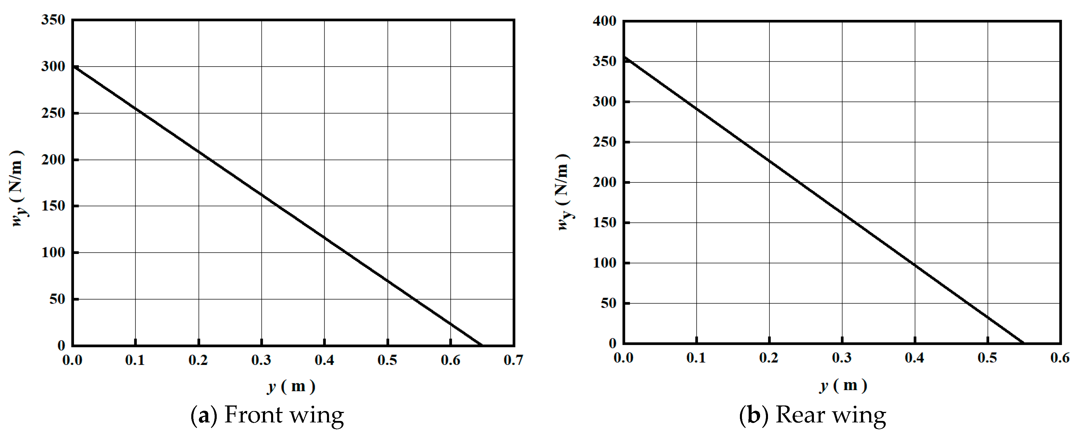
When adopting a quarter ellipse distribution, the distributed load w y corresponding to a different position y   in the direction of span is:
w y = 4 F π b 1 ( 2 y b ) 2 = 4 F w π b 1 / 2 1 ( y b 1 / 2 ) 2
where w y represents the distributed load acting on the wing at a specific coordinate y along the wing span,   F denotes the total load resulting from a particular distributed load on the wing, and b represents the wingspan. F w signifies the total load on a single wing, which can be specifically calculated using Equation (3), as seen below.
F w = m · n · g   /   2
Substituting specific values to derive the frontal wing load distribution along the span direction can be expressed as follows:
w y = 192 1 ( y 0.65 ) 2
The rear wing load distribution along the span direction is:
w y = 226 1 ( y 0.55 ) 2
where the unit of w y is in N/m, the unit of y is in m, and the corresponding distribution curve is shown in Figure 3. Through integration, the total shear force is calculated to be 49 N.
(2)
Triangular distribution
When utilizing the triangular distribution, the distributed load w y corresponding to a different position y in the direction of span is:
w y = 2 F b ( 1 2 y b ) = 2 F w b 1 / 2 ( 1 y b 1 / 2 )
Substituting specific values to obtain the front wing load distribution along the span direction results in the following equation:
w y = 301 ( 1 y 0.65 )
The rear wing load distribution along the span direction is:
w y = 356 ( 1 y 0.55 )
The unit is the same as that in Formula (5), and the corresponding distribution curve is shown in Figure 4. The total shear force obtained through integration is also approximately 49 N.
Through theoretical analysis and calculations, the following criterion can be established: if the shear force value at a specific location on the wing exceeds the total design load (in this case, the critical value is 49 N), it is considered that structural damage has occurred in the UAV, and vice versa. The correctness and effectiveness of the criterion will be validated through numerical simulation methods and explosive damage experiments.

3. Numerical Simulation for Damage of UAVs under Blast Waves

3.1. Numerical Simulation Model

Due to the involvement of explosive impact in the damage assessment of UAVs, the AUTODYN software was adopted for numerical simulation research. AUTODYN is a nonlinear explicit dynamic analysis software widely used to simulate detonation, high-speed impact, and other problems [19]. The software features numerous excellent solvers, including Euler, Lagrange, ALE, SPH, etc., as well as hundreds of commonly used material databases and comprehensive fluid–structure interaction technology [20], making it highly suitable for this research.
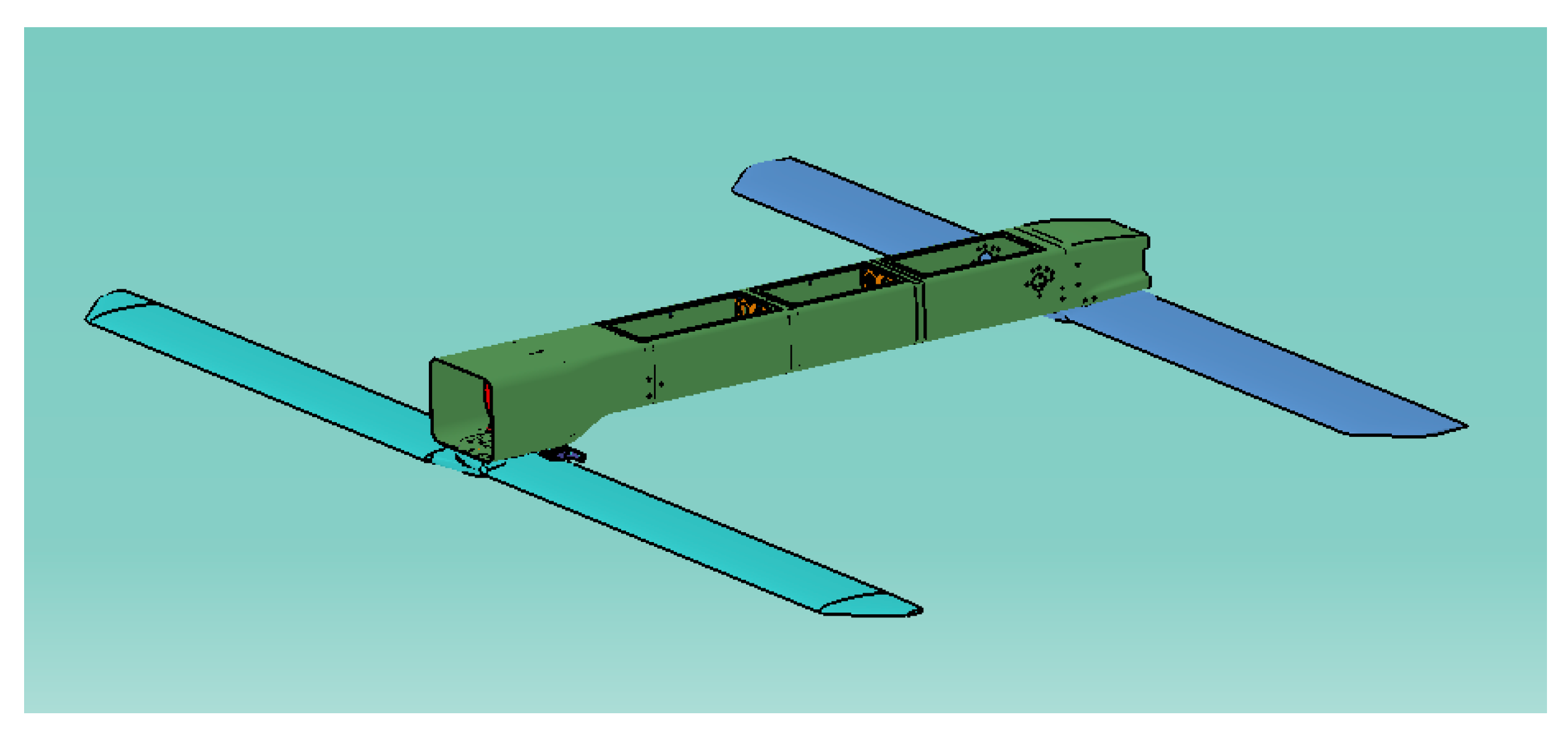
Numerical simulation was employed to investigate the overall load imposed on the UAV by blast waves. According to the actual dimensions of the UAV, a discretized model of the wing and the body was established, as shown in Figure 5, where the load area and mass of the wing were exactly the same as the real situation. Ignoring the complex structures inside the wings and fuselage, the equivalent was solely based on mass and stiffness.
The blast wave is distinguished by a rapid rise in incident pressure to a peak value, followed by a decrease in atmospheric pressure (positive phase). Subsequently, the incident pressure further diminishes below the ambient atmospheric pressure, resulting in negative phase pressure. The pressure at any given moment is described by the modified Friedlander’s equation as follows [21]:
P t = P 0 + P S 0 + ( 1 t t p o s ) e θ ( t   t p o s )
where P t represents the incident overpressure at any time instant, P 0   represents the ambient pressure, and P S 0 + signifies the peak positive incident overpressure. The durations of the positive phases of the incident blast wave are represented by t p o s , and θ is the decay parameter of the wave.
The numerical simulation mainly involves a comp B explosive, air and carbon fiber composite materials. The JWL (Jones–Wilkins–Lee) equation of state was used to describe the expansion process of detonation products for explosives. This equation describes the relationship between pressure, volume, and energy, as shown below [22,23]:
P = A ( 1 ω R 1 V ¯ ) e R 1 V ¯ + B ( 1 ω R 2 V ¯ ) e R 2 V ¯ + ω E V ¯
where P represents pressure, E denotes the initial volume energy of high explosives, V ¯   signifies the relative volume, and constant A , B , R 1   ,   R 2 and ω are pressure coefficients, the first and second eigenvalues, and the fractional part of the adiabatic exponent, respectively. Recessive parameters D C J and P C J are detonation velocity and detonation pressure, respectively. Table 1 shows the basic parameters of the JWL equation of the state of the comp B explosive.
The ideal gas equation of state is assumed for the air [25]:
P = ( γ 1 ) ρ e
where P is pressure, γ stands for the polytropic index, with a specific value of 1.4. ρ symbolizes density, and e denotes internal energy, with a value of 206.8 J/g.
The strength model of the carbon fibers employs a simple elastic model, where the stress and strain satisfy a linear relationship. Hooke’s Law in the present notation can be written as
P = K μ
where μ = ( ρ / ρ 0 ) 1 is the compressibility, ρ 0 is the initial density, and ρ is the current density. Additionally, the shear modulus K of the carbon fiber composite material is 2.69 × 10 6   kPa.
The carbon fiber composite material uses the Mie–Grüneisen EOS (Equation of State) to describe its structural response under the blast waves. The Mie–Gruneisen EOS based on the shock Hugoniot is expressed as [26]:
P = P H + Γ ρ ( e e H )
where Γ is the Gruneisen Gamma coefficient and equal to B 0 / ( 1 + μ ) , B 0 is a constant, and Γ ρ = Γ 0 ρ 0 = constant is assumed. P H and e H are the Hugoniot pressure and energy, respectively, given by
P H = ρ 0 c 0 2 μ ( 1 + μ ) [ 1 ( s 1 ) μ ] 2
and
e H = 1 2 P H ρ 0 [ ( 1 + μ ) μ ]
where c 0 is the sound speed in the material and s is a constant giving the slope of shock velocity–particle velocity relationship. The constants in the previous equations were taken from the material library.
Numerous studies indicate that the choice of simulation algorithms significantly impacts the accuracy of the final calculation results [27,28,29,30,31]. In the case of interaction between the blast wave and the UAV, there were both explosive detonation processes and interaction processes between detonation products, air, and the UAV. The Lagrange algorithm was chosen for the UAV to describe the structural response under impact. The Euler algorithm was selected for the explosive and air because it was better suited for describing the expansion process of detonation products and blast shock waves in the air. Figure 6 depicts the numerical simulation model of the UAV damage caused by the blast shock wave. To account for symmetry, only half of the simulation model was constructed. Mesh independence analysis was also conducted. Taking into account computational efficiency and ensuring calculation accuracy, the mesh size used in the simulation was set to 2 mm.

3.2. Numerical Simulation Results

Taking into account the safety and economy of the explosion test, a 500 g Comp B explosive was selected as the damage source for subsequent numerical simulations and prototype explosion experiments. Incorporating the critical shear force values obtained from theoretical calculations, preliminary numerical simulation results indicate that the critical distance for overall damage to the UAV under this condition is approximately within the range of 1.6 m to 1.8 m. Considering errors in numerical simulations, experimental measurements, and UAV design, this study conservatively chose two typical distances, specifically, placing the two UAV models at distances of 1 m and 2.5 m from the center of the explosive, respectively. It is anticipated that 2.5 m serves as a safe distance, while the UAV at 1 m is expected to experience overall destruction.
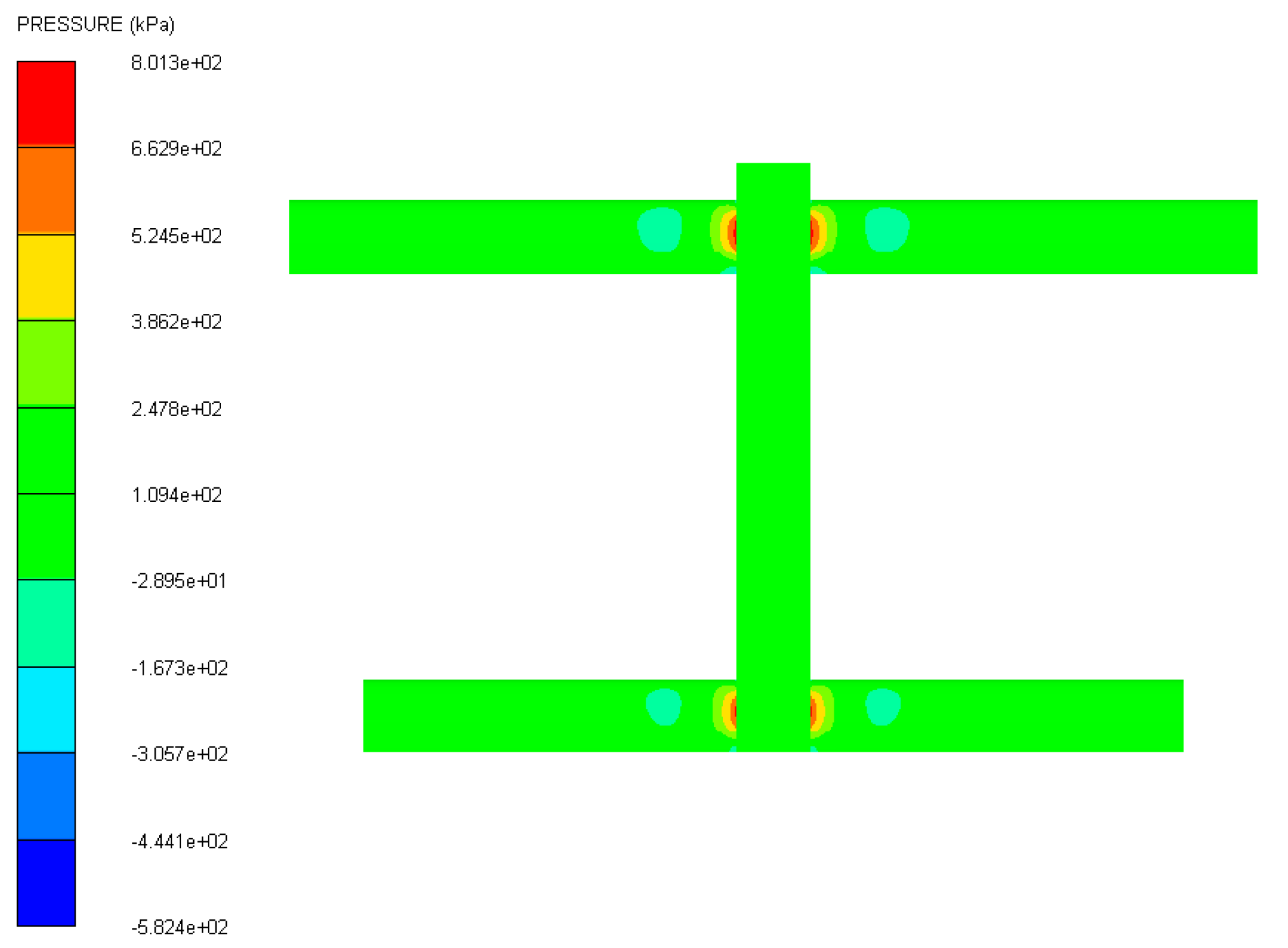
Numerical simulation shows that the peak overpressure of the shock wave was 0.56 MPa and 0.077 MPa for 1 m and 2.5 m of distance from the explosion center, respectively. Figure 7 displays a pressure distribution cloud map on the UAV under explosive loading. It is evident that the UAV’s response to the explosive load is concentrated at the connection point between the wing and the fuselage, where the pressure values are highest. This area is most vulnerable to damage.
Figure 8 depicts the pressure distribution on the end face of the wing under the influence of explosive loads at different distances (1 m and 2.5 m). Cross-sectional data analysis reveals that when the UAV was positioned 1 m away from the explosion center, the shear forces at the leading and trailing edges of the wing root measure 87.3 N and 79.4 N, respectively (shear force values can be directly obtained from the simulation software), which exceeded the wing’s total design load (49 N). Nevertheless, when the distance from the explosion center was 2.5 m, the shear forces for the front and rear wings were 20.5 N and 19.2 N, respectively, which were less than the total wing design load (49 N).
By comparing the maximum shear force values obtained from numerical simulations at the wing with the critical shear force values derived from theoretical calculations, it can be inferred that under the impact of 500 g of explosives, the UAV will not experience significant damage when positioned 2.5 m away from the explosion center, while it will suffer overall destruction when positioned 1 m away. This conclusion will be further validated through prototype explosive testing.

4. Experiment for Damage of UAVs under Blast Waves

4.1. Experimental Method

We conducted explosion experiments to analyze the damage effects of blast waves on typical UAV targets in order to validate the reasonability of using critical shear forces at the wing as an assessment criterion for UAV destruction. A 500 g comp B explosive was used to explode to form blast waves, which act on UAVs at typical distances. The distances between the two UAVs and the explosion center are 1 m and 2.5 m, respectively, with the choice of explosion experiment distances aligning with the settings used in the numerical simulations. Figure 9 shows the layout of the experiment. The fuselages of the UAVs were placed perpendicular to the ground, and the horizontal line of the charge coincided with the center horizontal line of the UAVs. The pressure sensor was used to measure the blast wave pressure at 1 m and 2.5 m from the explosion center, and the damage process was recorded by a high-speed camera.

4.2. Experimental Results

The pressure sensor measured the blast wave pressure signal at 1 m and 2.5 m, and the overpressure was 0.89 MPa and 0.078 MPa after data processing, respectively. The peak overpressure of the blast wave at 2.5 m was in good agreement with the numerical simulation results, whereas the discrepancy at 1 m was relatively remarkable. The difference may be attributed to two factors. One is the system error caused by the instability of the near-field shock wave overpressure field, which includes sensor measurement errors. The other is the error caused by reflections from walls or the ground during the experimental test.
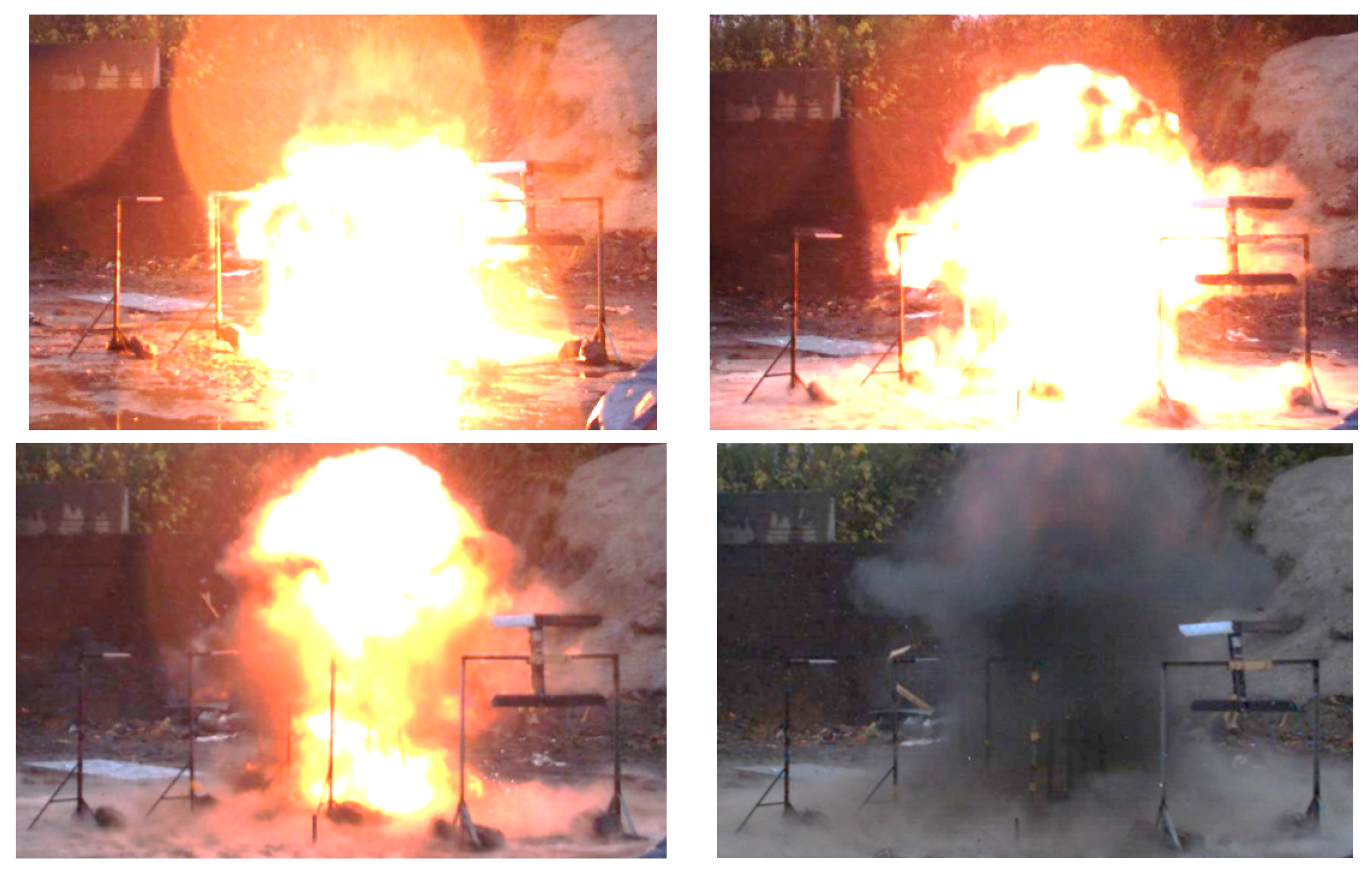
Figure 10 shows the experimental results of the damage to the UAVs caused by the explosion shockwave. It can be seen that the UAV at 1 m from the explosion center was damaged by the blast wave, and the wings flew along the direction of the shock wave. However, the wings and fuselage of the UAV located 2.5 m away from the explosion center were undamaged.
Figure 11 displays the recovered wing after the explosion experiment. It can be observed that the main body of the wing and the fuselage remain intact, with the wing only breaking at the connection point between the wing root and the fuselage. The experimental results have demonstrated that, under the influence of blast waves, UAVs are most susceptible to wing damage, leading to a cascade of safety concerns.
It was proved that the wing was the main component damaged by the blast wave in the explosive environment, and it was reasonable to use the failure shear force to judge the damage effect of the explosive shock wave on the UAV. The experimental observations are consistent with the results obtained from numerical simulations and theoretical calculations, thereby validating the reasonableness of employing the failure shear forces of wings to assess the damage effects of the explosive blast wave on the UAV.

5. Conclusions

From the perspective of structural strength design standards, a failure criterion based on the shear force experienced by the wing has been established for UAV targets under blast waves. The shear force value corresponding to the overall structural failure of a typical UAV was calculated. This failure criterion’s validity was further verified by comparing the results of explosive destruction tests with numerical simulations. The main conclusions are summarized as follows:
(1)
Based on the strength design criteria for UAVs, the key factor of the UAV structure strength design was analyzed, i.e., the shear force at the roots of wings. According to the wing load distribution equation, the theoretical critical failure shear force value for the typical UAV was calculated, and for this model, the numerical value is 49 N.
(2)
The overall shear force on the UAV wing due to the blast shock wave was obtained through numerical simulation. By combining the results of numerical simulation with theoretical calculations, two specific distances between the UAV and a 500 g explosive were preliminarily estimated: 1 m for complete destruction and 2.5 m for no significant structural damage. This provides a theoretical and numerical foundation for subsequent explosive experimental research.
(3)
The static explosion experiment was used to obtain the damage effect of a typical UAV under an explosive load. Under the impact of a 500 g explosive charge, the UAV located 1 m from the explosion center suffered the severe fragmentation of its wing, while the UAV positioned 2.5 m from the explosion center had its structure remain largely intact.
(4)
By comparing and analyzing the theoretical design load of the wing, numerical simulation results, and the extent of damage in the explosion experiments, the correctness and rationality of utilizing wing failure shear force to assess the overall damage effects of blast waves on UAVs have been validated.

Author Contributions

Conceptualization, X.F.; methodology, X.F. and Y.N.; software, X.F.; validation, Y.N.; formal analysis, X.F.; investigation, Z.Y.; writing—original draft, X.F., Z.Y. and Y.N.; writing—review and editing, X.F., Z.Y. and Y.N. All authors have read and agreed to the published version of the manuscript.

Funding

This research is supported by the National Natural Science Foundation of China (Grant no. 12102413).

Data Availability Statement

Data are contained within the article.

Conflicts of Interest

Author Zezhou Yang was employed by the company Nanjing Opatiya Information Technology Co., Ltd. The remaining authors declare that the research was conducted in the absence of any commercial or financial relationships that could be construed as a potential conflict of interest.

References

  1. Jiang, H.Z. Principles of Rocket Warhead Design; National Defense Industry Press: Beijing, China, 1982. [Google Scholar]
  2. Ball, R.E. The Fundamentals of Aircraft Combat Survivability Analysis and Design, 2nd ed.; American Institute of Aeronautics and Astronautics Inc.: Reston, VA, USA, 2003. [Google Scholar]
  3. Liu, T. Research on Lethality Assessment Method of Air Defense Warhead; Nanjing University of Science and Technology: Nanjing, China, 2004. [Google Scholar]
  4. Konokman, H.; Kayran, A.; Kaya, M. Aircraft vulnerability assessment against fragmentation warhead. Aero Sci. Technol. 2017, 67, 215–227. [Google Scholar] [CrossRef]
  5. Pei, Y.; Song, B.F.; Shi, S. Analysis method of aircraft combat survivability: Progress and challenge. Acta Aeronaut. Astronaut. Sin. 2016, 37, 216–234. [Google Scholar]
  6. Si, K.; Li, X.D.; Guo, C. Research on Damage Assessment Method of Fragmentation Warhead Against Airplane Targets. J. Ballist. 2017, 29, 52–57. [Google Scholar]
  7. Liang, B.; Feng, G.P.; Zhou, J.Q. Research on the Damage Effect of EFP Combined Warhead and Discrete Rod to Battleplane. J. Proj. Rockets Missiles Guid. 2017, 37, 39–45. [Google Scholar]
  8. Konokman, H.E.; Kayran, A.; Kay, M. Analysis of Aircraft Survivability against Fragmenting Warhead Threat: AIAA-2014.0355; AIAA: Reston, VA, USA, 2014; pp. 767–778. [Google Scholar]
  9. Mi, B.G. Simulation on the dynamic stability derivatives of battle-structure damaged aircrafts. Def. Technol. 2021, 17, 987–1001. [Google Scholar] [CrossRef]
  10. Pei, Y.; Chen, Z.W.; Wei, Y.H. Method for assessing combat survivability for aircraft with wing damage. Proc. Inst. Mech. Eng. Part G J. Aerosp. Eng. 2016, 231, 877–886. [Google Scholar] [CrossRef]
  11. Zhang, M.; Pei, Y.; Yao, X. Damage assessment of aircraft wing subjected to blast wave with finite element method and artificial neural network tool. Def. Technol. 2023, 25, 203–219. [Google Scholar] [CrossRef]
  12. Ju, S.J.; Kwak, H.G. A FE model to evaluate the resisting capacity of RC beams and columns under blast loading based on PI diagram. Int. J. Impact Eng. 2022, 161, 104–113. [Google Scholar] [CrossRef]
  13. Hamra, L.; Demonceau, J.F.; Denoel, V. Pressure-impulse diagram of a beam under explosion-Influence of the indirectly affected part. In Proceedings of the 7th European Conference on Steel and Composite Structures, Naples, Italy, 10–12 September 2014; Eurosteel: Belgium, Bruxelles, 2014. [Google Scholar]
  14. Huang, J.C.; Wang, H. Aircraft Structures Design and Analysis; Shanghai Jiao Tong University Press: Shanghai, China, 2012. [Google Scholar]
  15. Tao, M.Z. Comprehensive Design of Modern Aircraft Structure; Northwestern Polytechnical University Press: Xi’an, China, 2001. [Google Scholar]
  16. Zhang, S.L. Analysis of structural dynamic response for aircraft operating in the environment of nuclear explosion shock waves. Acta Aeronaut. Astronaut. Sin. 1992, 13, A510–A515. [Google Scholar]
  17. Feng, X.W.; Lu, Y.G.; Li, Y.Z. Damage Assessment Method of Aircraft Targets under Blast Wave. Chin. J. High Pressure Phys. 2019, 33, 045101-1–045101-5. [Google Scholar]
  18. Liu, Y.; Lu, P. Approximation Method for Calculating the Wing Load Envelope of Bending Moment and Shear Force. Adv. Aeronaut. Sci. Eng. 2013, 4, 241–246. [Google Scholar]
  19. Ding, L.L.; Tang, W.H.; Ran, X.W. Simulation study on jet formability and damage characteristics of a low-density material liner. Materials 2018, 11, 72. [Google Scholar] [CrossRef] [PubMed]
  20. Ding, L.; Cui, X.; Lu, L.; Yin, X. Rapid Evaluation of the Destructive Power Caused by Accidental Explosion of Space Launch Vehicles. Aerospace 2024, 11, 117. [Google Scholar] [CrossRef]
  21. Alogla, A.; Helal, M.; ElShafey, M.M. Numerical Analysis for Critical Structures Protection against Blast Loading Using Metallic Panels. Appl. Sci. 2020, 10, 2121. [Google Scholar] [CrossRef]
  22. Wilkins, M.L. Calculation of Elastic-Plastic Flow. J. Biol. Chem. 1964, 280, 12833–12839. [Google Scholar]
  23. Lee, E.L.; Finger, M.; Collins, W. JWL Equation of State Coeffients for High Explosives; Lawrence Livermore National Laboratory Report; UCID-16189; Lawrence Livermore National Laboratory: Livermore, CA, USA, 1973. [Google Scholar]
  24. Dobratz, B.M.; Crawford, P.C. LLNL Explosives Handbook: UCRL-52997; Lawrence Livermore National Laboratory: Livermore, CA, USA, 1985. [Google Scholar]
  25. Izadifard, R.A.; Foroutan, M. Blast wave parameters assessment at different altitude using numerical simulation. Turk. J. Eng. Environ. Sci. 2010, 34, 25–41. [Google Scholar]
  26. Andre, M.M. Dynamic Behavior of Materials; John Wiley & Sons: Hoboken, NJ, USA, 1994. [Google Scholar]
  27. Shang, Y.L.; Xu, X.; Zhang, D. The loading discrepancies in conwep and fluid-structure interaction methods and the masonry wall dynamic response characteristics. Acta Armamentarii. 2023, 44, 3897–3908. [Google Scholar]
  28. Liu, Z.X.; Jiang, J.W.; Li, M. High Precision Simulation Analysis of the Influence of Ring on EFP Forming Properties. Acta Armamentarii. 2024, 1–11. [Google Scholar] [CrossRef]
  29. Mo, C.F.; Zhou, Y.B.; Fu, T.Q. Research on numerical simulation method of test bench under explosion impact. J. Ordnance Equip. Eng. 2022, 43, 165–171. [Google Scholar]
  30. Shi, T.D.; Chen, F.Z.; Yan, H. Numerical simulation of explosive separation of mild detonating fuse based on coupling algorithm of smoothed particle hydrodynamics with finite element method. Explos. Shock Waves 2022, 42, 39–52. [Google Scholar]
  31. Hu, Y.F.; Zhang, H.L.; Chen, Z.Q. Numerical simulation research on warhead fragmentation shape and fragments scattering characteristics. J. Ordnance Equip. Eng. 2024, 45, 72–78. [Google Scholar]
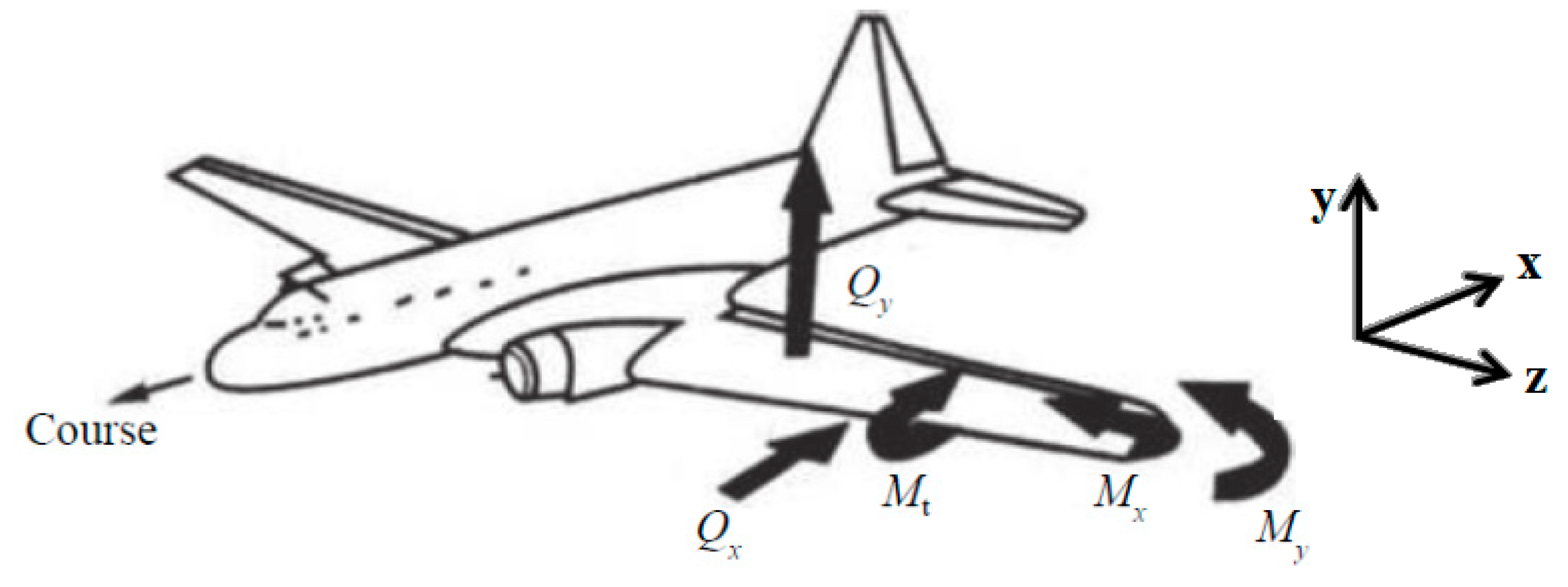
Figure 1. The schematic diagram of the load acting on the wing.
Aerospace 11 00651 g001
Figure 2. UAV wing outline drawing.
Aerospace 11 00651 g002
Figure 3. Quarter elliptical load distribution curve.
Aerospace 11 00651 g003
Figure 4. Triangular load distribution curve.
Aerospace 11 00651 g004
Figure 5. Discretized model of the UAV.
Aerospace 11 00651 g005
Figure 6. The numerical simulation model of the UAV damage caused by the blast shock wave.
Aerospace 11 00651 g006
Figure 7. The pressure cloud map of the UAV at the explosion distance of 2.5 m.
Aerospace 11 00651 g007
Figure 8. Pressure cloud maps on the end face of the UAV wing at different distances under perpendicular blast wave loading.
Aerospace 11 00651 g008
Figure 9. Experimental setup for UAVs under blast waves.
Aerospace 11 00651 g009
Figure 10. Experiment result photos of damage to UAVs caused by explosive shock waves.
Aerospace 11 00651 g010
Figure 11. The image of the recovered wing after the explosion experiment.
Aerospace 11 00651 g011
Table 1. Basic parameters and JWL parameters of comp B explosive [24].
ρ /(g/cm3) A ′/GPaB′/GPa R 1 R 2 ω D C J /(m/s) P C J /GPa E /(J/mm3)
1.72524.27.74.21.10.34798029.58.5
Disclaimer/Publisher’s Note: The statements, opinions and data contained in all publications are solely those of the individual author(s) and contributor(s) and not of MDPI and/or the editor(s). MDPI and/or the editor(s) disclaim responsibility for any injury to people or property resulting from any ideas, methods, instructions or products referred to in the content.