Abstract
Numerical simulations were conducted to analyze the unsteady aerodynamic characteristics of a tiltrotor aircraft with different conversion strategies. Firstly, the CFD method was established by taking the interaction between the rotor and wing into account, as well as the body-fitted grid of the tiltrotor. Then, the trimming approach of the rotor and wing was developed to ensure longitudinal balance of the aircraft, and the method for determining the conversion corridor of the tiltrotor aircraft was proposed by considering the limitations imposed by wing stall and the required power of the rotor. Finally, the aerodynamic characteristics of the rotor and wing during the continuous conversion process were investigated, considering various tilting angular velocities and horizontal accelerations of the tiltrotor. The numerical results indicated that a smaller acceleration can enhance the efficiency of the tiltrotor. However, this would increase the complexity of trimming the fuselage attitude angle. It was also found that excessive acceleration could exceed the required power limit of the tiltrotor, rendering the conversion strategy infeasible.
1. Introduction
The tiltrotor aircraft is a novel type of aircraft that boasts vertical takeoff and landing capabilities, as well as the ability to hover and achieve high-speed forward flight. In recent years, the development of tiltrotor aircraft has become a hot topic, with typical representatives being Bell’s V-280 tiltrotor aircraft [1] and Leonardo’s NGCTR (Next Generation Civil Tilt Rotor) [2,3]. Both types of tiltrotor aircraft adopt a nacelle non-tilting strategy, reducing aerodynamic drag and control difficulty during the tilting procedure, which is the key process for transitioning between helicopter and fixed-wing modes. During the conversion procedure, the tiltrotor undergoes simultaneous tilting, rotating, and pitching motions, resulting in the emergence of a strong vortex wake in the flowfield. The wake undergoes dynamic changes, such as complex bending and distortion, etc. Additionally, there are transient aerodynamic interactions between the tiltrotor and the wing [4], which lead to distinct unsteady variations in the local lift, drag, and moment of both the rotor and the wing. The intricate unsteady aerodynamic characteristics exhibited by the rotor and wing during the conversion phase pose challenges in maintaining the balance of total aerodynamic forces between the tiltrotor and the wing. Consequently, comprehensive investigations regarding the unsteady aerodynamic characteristics and trimming strategies of both the tiltrotor and the wing in the conversion procedure are of utmost importance.
Ma et al. established a calculation model to analyze the flowfield of tiltrotor aircraft by considering the aerodynamic interactions between the rotor and wing [5]. While the free wake method can provide an initial calculation of the unsteady aerodynamic characteristics during the conversion procedure, it has limitations in simulating the detailed evolution of the tip vortex and the aerodynamic interactions. The increasing computational power of computers has made the computational fluid dynamics (CFD) method an essential tool for studying the aerodynamic characteristics of tiltrotor aircraft. Xu et al. [6] utilized the CFD method to analyze the ground effect and fountain effect of the V22 tiltrotor in hover, which fully showcased the advantages of the CFD method in aerodynamic analysis. Chen [7] employed the momentum source method, known for its high computational efficiency, to calculate the unsteady aerodynamic forces of the tiltrotor aircraft during the conversion mode. Although the momentum source method could capture the aerodynamic interaction between the tiltrotor and the wing/fuselage to some extent, it was difficult to effectively simulate the detailed evolution of the rotor tip vortices. Sheng et al. [8] calculated the aerodynamic characteristics of a quad tiltrotor aircraft in both fixed-wing aircraft mode and conversion mode with specific tilt angles of the rotor. The aerodynamic interactions of the front twin-rotor and the rear twin-rotor were effectively simulated based on the Navier–Stokes equations and a body-fitted grid. Yong et al. [9] conducted unsteady flow calculations of a tiltrotor UAV using an unstructured mesh flow solver coupled with an overset mesh technique. The aerodynamic interactions between the prop-rotor and the tail-wing were analyzed with 80° and 90° nacelle tilt angles. Truong et al. [10] conducted numerical investigation of aerodynamic interactions for the tiltrotor and wing of Next Generation Civil Tilt Rotor (NGCTR) VTOL aircraft with a tilted nacelle by employing the NSMB CFD solver and multi-block structured grids, and further carried out flow control study by synthetic jet. However, these three references only investigated the aerodynamic interaction characteristics of the tiltrotor and wing in specific tilt angle states, without considering the unsteady changes in the aerodynamic forces of the rotor and wing during the continuous tilting process of the tiltrotor. The CFD method, utilizing a rotor body-fitted grid, enables the calculation and analysis of unsteady aerodynamic characteristics of the rotor and wing in a continuous tilting process. However, this CFD technology presents significant challenges, including the need to develop a robust moving embedded grid method, implement a high-precision numerical simulation algorithm, and address the time-consuming nature of the calculations.
The combination of aerodynamic forces from the rotor and wing renders flight control of tiltrotor aircraft redundant during the conversion procedure. Moreover, the complexity of aerodynamic characteristics and the unsteady variation of aerodynamic forces further compound the difficulties in trimming the rotor and controlling the flight during conversion [11]. Several studies have aimed to investigate the flight control characteristics of tiltrotor aircraft during the conversion procedure, leading to the development of analysis software such as GTRS [12]. Appleton utilized the TARA code to model and investigate the effects of rotor/fuselage interaction on the conversion corridor of tiltrotor aircraft [13]. The analysis revealed that empennage interactions significantly influence the trim behavior of the entire aircraft during conversion. Sheng et al. established an aerodynamic force model for the rotor [14], employing the blade element and lift line theories, and analyzed the stability of the XV-15 tiltrotor aircraft by incorporating aerodynamic models for the fuselage, wing, horizontal tail, and vertical tail. Wu et al. employed the blade element theory and the Pitt–Peters dynamic inflow to simulate the flight dynamic characteristics of a small tiltrotor UAV during the conversion procedure [15]. However, the studies mentioned above predominantly utilized simplified models to analyze rotor aerodynamics, requiring several correlation parameters based on experimental data. Govdeli et al. conducted flight simulations of tiltrotor quadplane configurations using an unsteady aerodynamic model of the rotor based on the vortex method [16,17]. Lyu et al. established a rotor aerodynamic model for the tilt quadrotor aircraft using the Goldstein vortex method and optimized the tilting path in the conversion corridor [18], thereby resolving control redundancy and ensuring stability of the height and attitude during the conversion process. However, the coupling of rotation and tilting motions in the conversion state introduces extremely complex unsteady flow characteristics, and simplified aerodynamic models struggle to accurately predict the flight characteristics of tiltrotor aircraft. To more accurately explore the aerodynamic characteristics and control features of the conversion state, a research method with higher precision is required. Therefore, this paper utilizes the CFD method to simulate the aerodynamic characteristics of the tiltrotor and wing during the conversion procedure and investigates the trimming strategy between the rotor and wing of the tiltrotor aircraft.
Current research on the unsteady aerodynamic characteristics of the tiltrotor and wing mainly focuses on the aerodynamic interference characteristics and trimming strategy with a fixed tilt angle. Although these can also guide the design of transition corridors and flight control for tiltrotor aircraft, the analyses of fixed tilt angles still have limitations because the tilting process is unsteady. The innovation of this paper is to investigate the evolution of aerodynamic forces and state variables for tiltrotor and wing during different continuous tilting strategies of tiltrotor, such as tilting path and angular velocity, based on CFD simulation of aerodynamic interaction for tiltrotor and wing.
To investigate the effective strategy for matching aerodynamic forces between the rotor and wing during conversion flight, the CFD method was established based on moving embedded grids and unsteady Reynolds-averaged Navier–Stokes (URANS) equations. This method was enhanced by incorporating blade element momentum theory (BEMT) to accurately determine the manipulation of the rotor during tilting, thereby simulating the aerodynamic characteristics of the rotor and wing. Subsequently, the conversion corridor for the tilting rotors and wing was calculated by evaluating the low-speed stall boundary and the high-speed required power boundary. Finally, the unsteady aerodynamic characteristics of the tiltrotor and wing on various conversion paths were simulated by the developed CFD method and trimming strategy.
2. Aerodynamic Trimming Method of Tiltrotor in Conversion Procedure
2.1. Numerical Methods for Aerodynamic Forces Simulation of Tiltrotor
For the investigations of aerodynamic trimming of the tiltrotor, both the CFD method based on moving embedded grids and the BEMT method [19] are adopted to calculate the aerodynamic forces of the tiltrotor.
The aerodynamic performance of the tiltrotor can be calculated by coupling of the blade element and momentum theories, equalizing the same thrust and torque coefficients from the two theories, and the established system can be solved by numerical methods, such as Newton iteration. The non-dimensional formulation of the BEMT method is written as
where dCT and dCQ are the thrust and torque coefficients, respectively, of a specific blade element with non-dimensional chord located at of the blade; Cl and Cd the lift and drag coefficients of the blade section; the normalized velocity of the blade element; μ, λ, and ξ the advance ratio, axial, and the azimuthal induced factor; F the Prandtl’s tip-loss model; and N the number of blades. The up-indexes “MT” and “BE” indicate that the expression is derived from momentum theory or blade element theory.
To analyze the unsteady aerodynamic characteristics of a tiltrotor during the conversion procedure, the CFD method based on a moving embedded grid of the rotor and URANS equations is employed [20], which is an evolution of the CLORNS code [21]. The governing equations of URANS are expressed as follows:
where W refers to the conserved variables, Fc and Fv convective and viscous fluxes, V the volume of grid cell with surface S, and n the outward-pointing normal vector of S.
In this simulation, both the rotation and tilting motions of the rotor are considered simultaneously to capture the unsteady flowfield accurately. For the spatial discretization of the URANS equations, the Roe-WENO scheme is adopted, and the one-equation S–A turbulence model is utilized to solve the viscous fluxes. In addition, the time marching is performed using the dual-time LU-SGS method. More details of the solution method of URANS can be found in references [20,21].
The moving embedded grid system is adopted to simulate the aerodynamic interaction between the tiltrotor and wing during the conversion procedure, which consists of the C–O-type body-fitted grids around the rotor blades with moving boundaries, the C–H-type grid for the wing, the Cartesian transition grids, and background grids. More details of the grid system can be found in reference [22].
To verify the accuracy of the BEMT and CFD method, the XV-15 tiltrotor in hovering flight is chosen to calculate its aerodynamic performance. For the CFD method, three sets of embedded grids are generated, 245 × 50 × 66 (chordwise, normal, and spanwise directions) (coarse grid), 305 × 60 × 106 (medium grid), and 405 × 80 × 126 (fine grid) for blade and 91 × 110 × 95 (coarse grid), 91 × 110 × 95 (medium grid) and 121 × 140 × 120 (fine grid) for background. In addition, the grid height of the first layer on the blade surface is set to 1.0 × 10⁻⁶, ensuring y+ less than 1.0. Figure 1 shows the calculated figure of merit (FM) of the XV-15 tiltrotor by BEMT and CFD methods compared with experimental data at a tip Mach number of 0.69 standard blade tip speed, and the calculated values of FM agree well with the experimental data [23]. As can be seen, the medium and fine grids for CFD method can simulate the aerodynamic performance of tiltrotor in good agreement with the test, and the BEMT solver matches well with the CFD method and test. For the rest of the paper, a medium grid is used for aerodynamic characteristics of the tiltrotor.
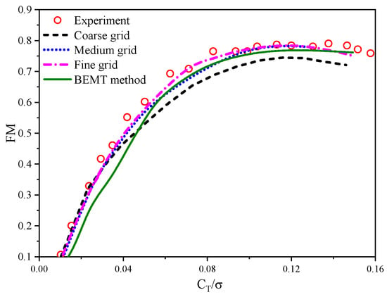
Figure 1.
Comparisons of figure of merit for XV-15 tiltrotor with different grids and methods.
2.2. Flight Dynamic and Balance Equations of Tiltrotor
The tiltrotor aircraft demonstrates a six-degrees-of-freedom (DOF) motion, which encompasses the equilibrium equations for the forces and rotational moments around the center of mass of the rotor. These equations can be expressed as follows:
where
are the linear and angular velocity of the aircraft, moments of inertia and the product of inertia about each axis, ϑ the pitching angle of the fuselage, and γ the rolling angle. The meanings of the lower marks in the formula are rotor (R), wing (W), fuselage (F), flat tail (H), and vertical tail (V).
The aim of trimming is to establish the manipulation and attitude angles of a tiltrotor aircraft under stable flight conditions, as determined by the equilibrium equations. The manipulations involved are the collective pitch, the lateral periodic pitch, and the longitudinal periodic pitch of the tiltrotor. The equations for trimming are as follows:
The objective of this paper is to analyze the trimming characteristics of the tiltrotor and wing during a stable conversion state. Therefore, only the longitudinal trim characteristics of the tiltrotor aircraft are considered. Figure 2 depicts the aerodynamic environment and forces experienced by the tiltrotor and wing during the conversion procedure. In the figure, Vc represents the flow velocity perpendicular to the rotor disc, while Vt is the flow velocity parallel to the rotor disc.
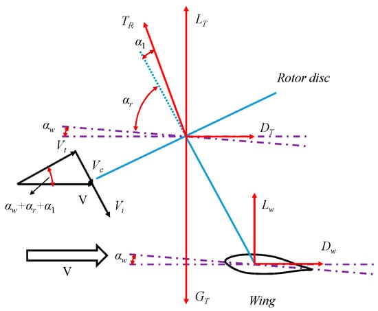
Figure 2.
Aerodynamic environment and forces of tiltrotor and wing in conversion procedure.
Therefore, the aerodynamic equilibrium equation of tiltrotor and wing can be simplified as:
where LT is the total lift, Fa the resultant force in horizontal direction, GT the gravity, TR the thrust of rotor, m the mass of the aircraft, a the acceleration of the aircraft, LW the thrust of wing, DW the drag of wing, αw the angle of attack (AoA) of wing, αr the tilt angle of rotor axis (90° when it is perpendicular to the horizontal line of fuselage, and 0° when it is parallel to the horizontal line of fuselage), and α1 the inclination angle of the rotor shaft.
2.3. Coupling Trimming Method of Tiltrotor and Wing in Conversion Procedure
In order to analyze the aerodynamic characteristics of the tiltrotor aircraft during the conversion procedure, a trimming strategy is proposed. Firstly, the conversion corridor of the aircraft is analyzed using the BEMT method. Following this, the corresponding tiltrotor manipulations are determined by setting a conversion flight strategy within the conversion corridor. In any given conversion state, the aerodynamic forces on the tiltrotor and wing can be expressed as a function of the collective pitch, longitudinal periodic pitches, and angle of attack (AoA) of the wing.
where is the rolling moment coefficient of the tiltrotor.
An efficient hybrid trim model is established based on the BEMT and CFD methods. This model combines the quick aerodynamic force predictions provided by BEMT for any conversion position of the tiltrotor with the accuracy ensured by the CFD method for the rotor performance. The partial derivative matrix of the manipulated variables during trimming is quickly calculated by using the BEMT method, and more accurate aerodynamic performance of tiltrotor and wing can be obtained from the CFD method by employing the iterative manipulation; thus, the aerodynamic forces of tiltrotor and wing are coupled by the values of the CFD method and the residual value of the BEMT method. The hybrid method can be formulated as follows:
where superscript i represents the number of iterative steps of the CFD method when the step of tilting angle for the tiltrotor is j, k the number of iterative steps of the BEMT model, and superscript d the target aerodynamic performance parameters. Figure 3 shows the procedure of the hybrid trimming method.
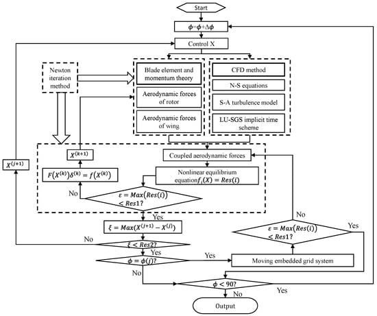
Figure 3.
Flowchart of hybrid trimming method.
The Newton iteration method [24,25] is employed to solve the equilibrium equations of tiltrotor aircraft. Let the nonlinear equations be:
where , and is the kth iteration approximation. The (k + 1)th iteration value is:
In the formula, , and .
Let , in which , so that and are obtained. In the Jacobian matrix, the partial derivative is replaced by the difference quotient, and the small iteration step length h is used, such that:
where , .
The procedure for solution of the nonlinear simultaneous equation by using the Newton method is as follows:
- Definition of the initial value ,
- Calculation of ,
- If is satisfied, the solution of the equations is , and the solution is completed; otherwise, the next step is entered,
- Computation of the Jacobian matrix ,
- Equation AZ = Res is solved, where , and is calculated,
- Calculation of ,
- The iteration step is updated by , and step 2 is returned until convergence.
2.4. Verification of the Trimming Method
To assess the efficacy of the hybrid trimming method, calculations of the aerodynamic performances of the XV-15 tiltrotor in various flight modes are conducted. Figure 4 presents a comparison between the trimming results and experimental data [26] regarding the aerodynamic characteristics of the tiltrotor. Specifically, subfigures a and b correspond to the cruise state, while subfigures c and d represent the conversion procedure. It is evident that the calculated results for rotor torque and thrust coefficient align well with the experimental values, thereby demonstrating that the established hybrid trimming method meets the requirements for aerodynamic modeling of tiltrotors.
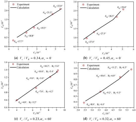
Figure 4.
The trimming results of the tiltrotor in different flight modes.
To further validate the efficacy of the trimming method coupled with the CFD model established in this paper, numerical simulations are conducted using the Robin helicopter rotor/fuselage model in forward flight. The simulations consider two advancing ratios of the rotor, μ = 0.15 and 0.23. The collective and periodic pitches of the rotor are trimmed and compared with the test data [27] across different flight states. The corresponding manipulations are summarized in Table 1.

Table 1.
Comparisons of rotor manipulations between calculation and test.
Figure 5 shows the distribution of the pressure coefficient on the fuselage surface at different flight states. The results indicate that the trimming method established in this paper can be effectively used for the determination of manipulation and simulation of aerodynamic characteristics for rotor and fuselage.
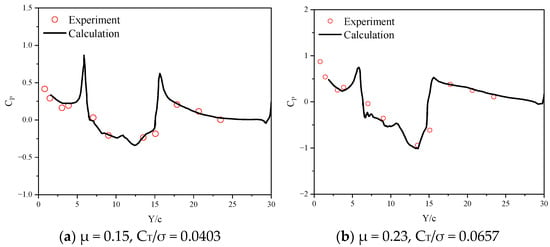
Figure 5.
Distribution of pressure coefficient at the top of the fuselage.
3. Analyses of Conversion Corridor
To ensure the stability and safety of a tiltrotor aircraft, the rotor must be tilted within a designated angle and flight-speed envelope. This envelope encompasses both low-speed and high-speed boundaries, which define the specific conversion corridor for the tiltrotor. The low-speed boundary aims to prevent wing stall, while the high-speed boundary sets limitations on the power required by the rotor, ensuring that it does not exceed the available power of the engine.
The XV-15 tiltrotor aircraft [28] is employed to simulate the conversion corridor. The rotor of the XV-15 aircraft consists of three large-twisted blades, and the values of the main parameters are shown in Table 2.

Table 2.
Main parameters of XV-15 tiltrotor.
3.1. Tilt-Angle–Speed Envelope on Low-Speed Boundary
The limitation of the low-speed boundary is the minimum flight speed of a tiltrotor aircraft at which the wing does not stall during the transition from helicopter mode to fixed-wing mode.
In helicopter mode, the rotor disk plane is controlled by longitudinal cyclic variation, which allows for the forward or backward tilt of the rotor disc. This adjustment enables the engine nacelle to tilt forward at a specific angle. The maximum forward tilt angle of the nacelle depends on the aircraft’s center of gravity, as well as the maximum backward tilt angle of the rotor.
where a1 is the backward tilt angle of the rotor disc, and xm and ym the longitudinal and vertical distances between the rotor hub center and the aircraft’s center of gravity, respectively.
In hovering flight, the maximum backward tilt angle of the rotor disc is determined by the variable pitching and flapping equivalent characteristics of the rotor.
When transitioning from hover to tilting mode, the forward speed of a tiltrotor aircraft generally remains relatively low. It is crucial during the engine nacelle tilting process to not only satisfy the thrust requirement for balancing the gravity and drag of the rotor and wing but also to prevent potential stalling of the wing at different tilt angles. Consequently, when calculating the low-speed tilting boundary within the conversion corridor, the wing should be adjusted to avoid reaching its critical angle of attack (AoA). Additionally, the relationship between the AoA of the wing and the AoA of the fuselage on the low-speed tilting boundary must satisfy the following conditions:
where αlj is the critical AoA of the wing, iw is the installation angle of the wing, and αf is the AoA of the fuselage.
By solving the equilibrium equations and the geometric relationship between the AoAs of the wing and fuselage, the tilt-angle–speed envelope on low-speed boundary is obtained, as shown in Figure 6.
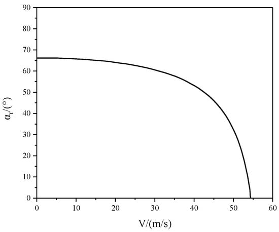
Figure 6.
Tilt-angle–speed envelope on low-speed boundary.
3.2. Tilt-Angle–Speed Envelope on High-Speed Boundary
When transitioning from fixed-wing aircraft mode to helicopter mode at high speeds, sufficient lift should be provided by the wing and rotor, while the horizontal thrust component of the tiltrotor must balance the drag of the entire aircraft. Additionally, it is crucial to ensure that the required power of the tiltrotor remains below the rated power Pn of the engine.
In forward flight, the calculation of the rotor required power for the XV-15 aircraft is conducted at specific engine nacelle tilt angles. The variations of the required power with different tilt angles and flight speeds are depicted in Figure 7. By considering the available power of the engine, the tilt-angle–velocity envelope on the high-speed boundary is ultimately determined, as presented in Figure 8.
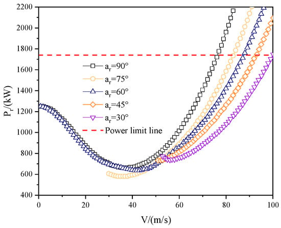
Figure 7.
Required power curve of tiltrotor at different tilt angle and flight speed.
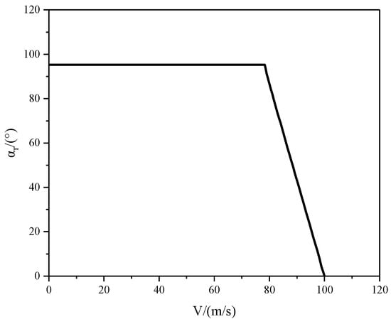
Figure 8.
Tilt-angle–speed envelope on high-speed boundary.
Figure 9 depicts the tilt-angle–speed envelope of the XV-15 tiltrotor aircraft on the high-speed boundary at various pitching angles of the fuselage. The numerical results indicate that successful tilt processes can be achieved through the combination of different fuselage angles of attack, engine nacelle angles, and forward flight speeds. Additionally, as the tilt-angle–speed envelope transitions from the low-speed boundary to the high-speed boundary, the AoA of the fuselage changes from positive to negative. To ensure the safety of the conversion process, a maximum speed is established, corresponding to a 45° nacelle angle on the high-speed boundary. Consequently, the forward flight speed must not exceed this specified speed during the tilting procedure.
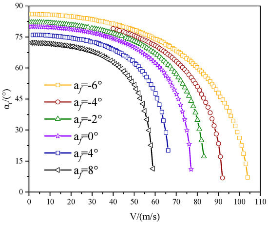
Figure 9.
Tilt-angle–speed of engine nacelle on high-speed boundary.
Figure 10 presents the conversion corridor of the XV-15 tiltrotor aircraft, which is derived from the combination of tilt-angle–speed envelopes on both the low-speed and high-speed boundaries. The figure compares the calculated conversion corridor to the flight test data [22], focusing solely on the aerodynamic characteristics of the rotor and wing. As a result, the conversion corridor based solely on the isolated rotor/wing exhibits a modest expansion compared to the overall range of the XV-15 aircraft. This expansion is attributed to the exclusion of drag effects from components such as the fuselage and vertical tail. Overall, the established calculation method for the conversion corridor of tiltrotor aircraft proves to be effective.
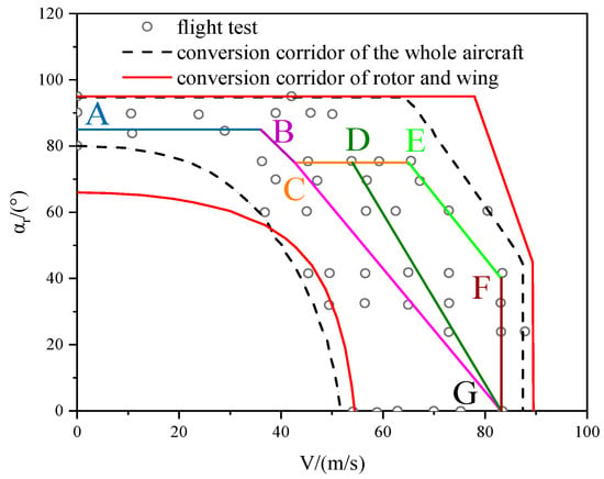
Figure 10.
Comparison of conversion corridor between calculation and flight test.
Figure 10 also illustrates the relationships between three specific conversion paths within the conversion corridor. All three paths initiate from a hover state with an engine nacelle tilt angle of 85°(point A in the figure). When the flight speed of the aircraft or rotor/wing reaches 36 m/s (point B in the figure), the engine nacelle begins to tilt at the same angular velocities towards point C (αr = 75°, V = 42.7 m/s) in the figure. Subsequently, various combinations of angular velocities and flight speeds are employed.
Conversion Path I (A-B-C-G): This path employs a constant angular velocity of the engine nacelle from point C in Figure 9 during the tilting process, resembling the actual tilting procedure. The flight speed reaches 83.2 m/s (point G in Figure 9) when the aircraft fully transitions from helicopter mode to fixed-wing aircraft mode.
Conversion Path II (A-B-C-D-G): Initially, the aircraft accelerates to 54 m/s (point D in Figure 9) while maintaining the same tilt angle of the engine nacelle. The engine nacelle then continues to tilt at a higher angular velocity than Path I until the aircraft completes its transformation into fixed-wing aircraft mode.
Conversion Path III (A-B-C-D-E-FG): Differing from Path II, the aircraft directly accelerates to 65.5 m/s (point E in Figure 9) from point C without tilting the engine nacelle. Subsequently, the engine nacelle tilts to 42° (point F in Figure 9, V = 83.2 m/s) at a constant speed. Finally, the engine nacelle continuously tilts until reaching fixed-wing aircraft mode with a constant flight speed. Notably, the forward flight speed remains consistently at 83.2 m/s for all three paths during the transition to fixed-wing aircraft mode.
4. Aerodynamic Characteristics of Tiltrotor in Conversion Procedure
4.1. Aerodynamic Characteristics of Rotor and Wing at Fixed Tilt Angle
4.1.1. Variation of Aerodynamic Forces of Rotor and Wing
The aerodynamic characteristics of the XV-15 tiltrotor and wing are investigated using the CFD method and trimming strategy at various specific tilt angles. Figure 11 presents the trimming results for the collective pitch of the rotor and the AoA of the wing under different flight conditions, considering different rotor tilt angles and flight speeds. As shown in Figure 11a, the collective pitch of the rotor initially decreases and then increases with an increment of forward flight speed, which is consistent with the behavior of conventional helicopters. A smaller rotor tilt angle requires a larger collective pitch at the same flight speed. Furthermore, Figure 11b illustrates that the AoA of the wing decreases as the flight speed increases, and the rate of AoA deduction varies based on rotor tilt angle. When the tilt angle of the rotor is 90°, the rate of AoA reduction increases with flight speed, whereas when the rotor tilt angle is 75°, the AoA of the wing follows a linear decreasing trend. In contrast, for rotor tilt angles less than 60°, the rate of AoA reduction decreases as flight speed increases. Additionally, Figure 11c,d display the thrust coefficient and required power of the rotor at different tilt angles and flight speeds. The required power and thrust coefficient exhibit a similar trend to that of the collective pitch for a specific tilt angle, and the turning point of the required power is almost identical to that of the collective pitch. However, the turning point of the thrust coefficient occurs at a higher forward flight speed.
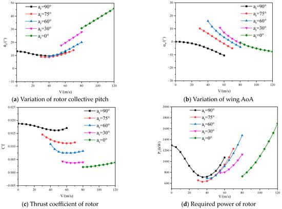
Figure 11.
Trimming values and aerodynamic characteristics of tiltrotor at fixed tilt angle.
Table 3 shows the proportion of lift for the rotor and wing at different tilt angles of the rotor on conversion path I (A-B-C-DG). It can be seen from the table that when the tiltrotor tilts 30° from hovering flight, the proportion of wing lift increases significantly, while the lift provided by the rotor decreases obviously. When the tilt angle is 30°, the proportion of lift provided by the tiltrotor is only 10.5%, and the lift of the aircraft is almost provided by the wing.

Table 3.
Proportion of lift for rotor and wing at fixed tilt angle.
4.1.2. Aerodynamic Interaction of Rotor and Wing
- (1)
- Case 1: αr = 0° (fixed-wing mode)
Figure 12 shows the spatial position of the rotor wake and the interaction with the wing, and further presents the streamline distribution of the 1/4-chord section of the wing. It can be seen from the figure that there is a clear vortex impact area on the upper surface of the wing, which is formed by the rotor tip vortex impacting the upper surface of the wing near the leading edge, indicating significant aerodynamic interaction between the rotor and the wing.
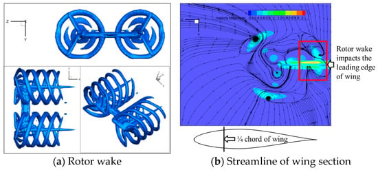
Figure 12.
Flowfield of rotor and wing.
Figure 13 shows the distribution of vorticity on the wing suction surface. It can be seen that the impact of the blade tip vortex causes a significant increase in vorticity on the wing surface. This is due to the large total pitch of the tiltrotor in this state, and the detached wake vortex in the middle section of the blade collides with the wing surface.
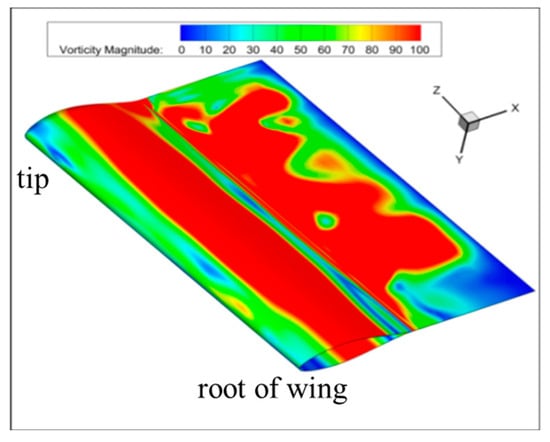
Figure 13.
Vorticity distribution on wing suction surface.
- (2)
- Case 2: αr = 30° (conversion mode)
Figure 14 shows the distribution of the rotor wake, and Figure 7 gives the vorticity and streamline of the flowfield between the rotor and wing. It is clear to see the distribution characteristics of the tip vortex and root vortex, as well as the changes after collision interference with the wing.
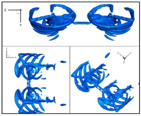
Figure 14.
Flowfield of rotor and wing with 30° tilt angle.
The vorticity distribution and streamline on the upper and lower surfaces of the wing are shown in Figure 15. As can be seen, the impact area of the downwash flow of the rotor on the upper surface of the wing is greater than that on the lower surface. In addition, it can be seen from the cross-sectional streamline of the wing that the blade tip vortex has a significant interaction effect on the root of the wing, and together with the incoming flow ahead, leads to a more complex three-dimensional flow phenomenon at the tip of the wing.
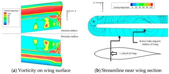
Figure 15.
Aerodynamic characteristics of wing under interaction with rotor wake.
4.2. Aerodynamic Characteristics of Rotor/Wing in Continuous Conversion Procedure
Based on the investigations of the conversion corridor above, the corresponding manipulations of the tiltrotor and wing are obtained through the solution of equilibrium equations. By adopting the conversion paths shown in Figure 9 and specifying three tilt angular velocities (1.5°/s, 3.0°/s, 4.5°/s) of the tiltrotor, the tilting characteristics and aerodynamic characteristics of the rotor/wing are investigated.
4.2.1. Influences of Paths on Aerodynamic Characteristics of Tiltrotor
The rotor in the conversion corridor undergoes a transition at an angular velocity of 1.5°/s along different paths. Figure 16 illustrates the results of the trimming and the aerodynamic characteristics of the rotor on path I. As shown in Figure 16a, the collective pitch of the tiltrotor initially decreases slightly and then rapidly increases with increment of flight speed, resembling the behavior of a helicopter in forward flight. However, the thrust coefficient of the tiltrotor decreases slightly at low speeds and then decreases rapidly at high speeds. Furthermore, the required power does not exceed the rated power of the engine, as shown in Table 2, and the highest power is required in hovering and cruising flight conditions. Due to the coupling of tilting angle, forward flight speed, horizontal acceleration, decreasing rotor thrust, and the aerodynamic interaction between the rotor and wing, a complex variation in the AoA of the wing occurs, as depicted in Figure 16b. During the initial process of the rotor transition from hovering to forward flight, the tiltrotor aircraft experiences nose-down pitches as it accelerates. However, when the nose-down pitch reaches a critical value, the tiltrotor is unable to provide sufficient vertical lift and horizontal thrust. Consequently, the negative lift and drag of the wing must be reduced by pitching upward. The rotor begins to tilt when the flight speed reaches 36 m/s, causing a loss of rotor lift. As the tilt angle of the rotor increases, the wing needs to contribute more lift, resulting in a continuous increase in the AoA of the wing. As the aircraft accelerates, although the lift of the wing still increases, the required lift coefficient and AoA gradually decrease due to the inverse relationship between lift coefficient and dynamic pressure (including the velocity squared term). This trend persists until the aircraft completely transitions to the fixed-wing flight mode.
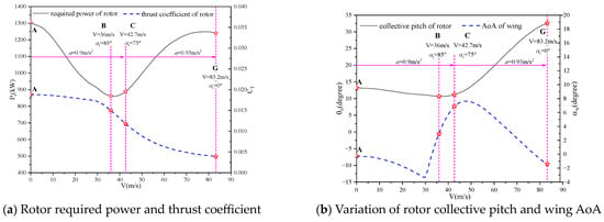
Figure 16.
Trimming values and aerodynamic characteristics of tiltrotor on path I.
Figure 17 presents the results of trimming and the aerodynamic characteristics of the tiltrotor on path II. In comparison to path I, the trend in the variation of the rotor collective pitch remains almost the same. However, the AoA of the wing undergoes significant changes due to the reduced acceleration of the aircraft between points B and G. The varying tilting strategies also result in a decrease in both the thrust and the required power generated by the rotor, as depicted in Figure 17b. Therefore, a slight acceleration would be beneficial for improving the aerodynamic efficiency of the rotor, although it would increase the complexity of the fuselage attitude.
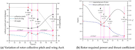
Figure 17.
Trimming values and aerodynamic characteristics of tiltrotor on path II.
Figure 18 presents the manipulation strategy and aerodynamic characteristics of the tiltrotor on path III. As can be seen, after point B, as the acceleration increases between points B and F, the collective pitch experiences a sudden increase at the initial process between points B and C, resulting in larger collective pitches of the rotor and a smaller AoA of the wing. Moreover, the required power and thrust coefficient of the rotor increase significantly compared to paths I and II, as shown in Figure 19. Additionally, the required power exceeds the rated power of the engine after reaching point E. Therefore, this indicates that although the tilt-angle–speed is within the conversion corridor, excessive acceleration might lead to impractical flight strategies.
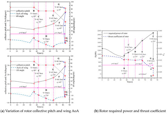
Figure 18.
Trimming values and aerodynamic characteristics of tiltrotor on path III.
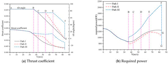
Figure 19.
Comparisons of aerodynamic characteristics of rotor on different titling paths.
Figure 19 presents a comparison for the thrust coefficient and the required power of the rotor at various tilt-angle–speed paths within the conversion corridor. The results indicate that a moderate acceleration is advantageous in decreasing the required power of the rotor while increasing the aerodynamic margin during the conversion process.
4.2.2. Influences of Tilting Angular Velocity
The tilt-angle–speed conversion corridor is primarily defined by two important parameters: tilt angle and speed. While the impacts of flight speed strategy on rotor manipulation and aerodynamic characteristics during the conversion process have been discussed previously, this section will further investigate the influences of tilt angle.
Figure 20 displays the variations of rotor manipulation and aerodynamic characteristics for path I, as illustrated in Figure 9, with different tilting angular velocities. As evident from the figure, the trend of lift changing with flight speed remains consistent across various tilting angular velocities. Specifically, Figure 20a,b demonstrate that the collective pitch of the rotor increases with the increment of tilting angular velocity, whereas the angle of attack (AoA) exhibits an overall decreasing trend. Consequently, the thrust coefficient and required power of the rotor also increase, as depicted in Figure 20c,d, respectively. However, it is worth noting that at high flight speeds, the required power may approach, or even exceed, the rated power of the engine due to the large tilting angular velocity. Hence, it is more suitable to employ a moderate tilting angular velocity for the conversion process of a tiltrotor.
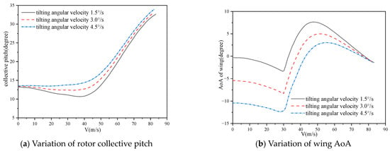
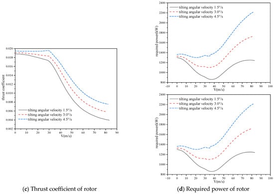
Figure 20.
Comparisons of aerodynamic characteristics of tiltrotor with different tilting angular velocities (path I).
Figure 21 provides further illustrations of the variations in rotor manipulation and aerodynamic characteristics for path II. The trends observed in the collective pitch of the rotor, AoA of the wing, thrust coefficient, and required power are similar to those depicted in Figure 20 at different tilting angular velocities. This indicates that changes in tilting angular velocity do not alter the trends of the aerodynamic characteristics; however, these changes do result in overall increases or decreases in the values of both the manipulation and aerodynamic characteristics of the rotor.
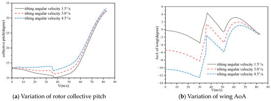
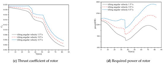
Figure 21.
Comparisons of aerodynamic characteristics of tiltrotor with different tilting angular velocities (path II).
4.2.3. Evolutions of Aerodynamic Forces for Tiltrotor and Wing
Based on the various tilt-angle–speed paths explored above, it becomes evident that path I, characterized by a low tilting angular velocity and small acceleration, is more reasonable. Figure 22 and Figure 23 present the matching features of the lift generated by the rotor and wing under two different tilt-angle–speed strategies, respectively. In the first strategy depicted in Figure 22, when the rotor shaft tilt angle is 59° and the forward flight speed is 45 m/s, the lift produced by the rotor and wing is equal, indicating that the wing begins to bear most of the gravity burden for the entire aircraft. In the second strategy illustrated in Figure 23, the intersection points of the wing and rotor lift curves occur at a rotor shaft angle of 55° and a forward flight speed of 59 m/s. Thus, a low tilting angular velocity and small acceleration facilitate the transition from rotor-lift dominance to wing-lift dominance at higher tilt angles and lower flight speeds.
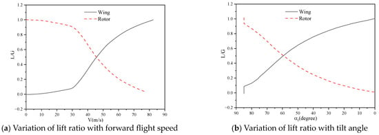
Figure 22.
Lift matching and variation of rotor and wing on path I (1.5°/s).
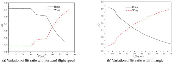
Figure 23.
Lift matching and variation of rotor and wing on path II (3°/s).
5. Conclusions
A coupling trimming method for tiltrotor aircraft during the conversion procedure is established by combining the BEMT method with the CFD method based on moving embedded grids and URANS equations. Using this method, the conversion corridor is calculated. Based on these foundations, the unsteady aerodynamic characteristics of the tiltrotor and wing are investigated for different conversion paths with various tilting rates and flight speeds, leading to the following conclusions:
The coupling trimming method, based on the CFD method, enables precise determination of the tiltrotor aircraft manipulation during different flight modes. Additionally, the calculation method for the conversion corridor effectively identifies the appropriate path for the tiltrotor aircraft.
Using the conversion corridor obtained in this study, several conversion paths are designed with different tilt rates and accelerations. The simulated aerodynamic characteristics of the rotor and wing indicate that changes in tilt angular velocity do not alter the overall trend of the tiltrotor’s aerodynamic characteristics. However, they do influence the manipulation and the aerodynamic characteristics of the rotor and wing.
By comparing the conversion paths with varying tilt rates and accelerations, it is found that a smaller acceleration improves the efficiency of the rotor but increases the complexity of the fuselage attitude angle. Conversely, a larger acceleration might make the conversion path infeasible.
During the conversion process, a lower-pitch angular velocity and smaller acceleration can facilitate the transition from rotor-lift dominance to wing-lift dominance at higher pitch angles and lower flight speeds.
In this paper, the evolution of aerodynamic forces and state variables for tiltrotor and wing during different continuous tilting strategies of tiltrotor are investigated, which may provide a theoretical foundation for deeply revealing the aerodynamic matching mechanism between the tiltrotor and the wing during conversion, as well as the design of flight control laws for tiltrotor aircraft.
Author Contributions
Conceptualization, G.Z. and Q.Z.; methodology, G.Z. and X.C.; software, G.Z. and Z.C.; validation, G.Z., Z.C., and X.C.; formal analysis, G.Z.; investigation, G.Z., Q.Z., and X.C.; resources, Z.C. and P.L.; data curation, Z.C. and P.L.; writing—original draft preparation, G.Z. and Z.C.; writing—review and editing, G.Z. and X.C.; visualization, G.Z. and Z.C.; supervision, Q.Z. and X.C.; project administration, Q.Z. and X.C.; funding acquisition, G.Z. All authors have read and agreed to the published version of the manuscript.
Funding
This research is supported by the National Natural Science Foundation of China (12072156), the Foundation of National Key Laboratory of Helicopter Aeromechanics (61422202103), and Priority Academic Program Development of Jiangsu Higher Education Institutions (PAPD).
Data Availability Statement
Data are contained within the article.
Conflicts of Interest
Author Peng Li was employed by the company Transwarp Technology (Shanghai) Co., Ltd. The remaining authors declare that the research was conducted in the absence of any commercial or financial relationships that could be construed as a potential conflict of interest.
References
- Risen, T. Future vertical lift demonstrators. Aerosp. Am. 2018, 56, 23–25. [Google Scholar]
- Belardo, A.M.; Beretta, B.J.; Marano, A.D. Design strategy of the wing of the Next Generation Civil TiltRotor Technology Demonstrator. In Proceedings of the 3rd Euro-Mediterranean Conference on Structural Dynamics and Vibroacoustics, Napoli, Italy, 17–19 February 2020. [Google Scholar]
- Marano, A.D.; Diodati, G.; Paletta, N. Structural scalability preliminary studies for the next generation civil tiltrotor composite wing. Aerospace 2023, 10, 478. [Google Scholar] [CrossRef]
- Garcia, A.J.; Barakos, G.N. Numerical simulations on the ERICA tiltrotor. Aerosp. Sci. Technol. 2017, 64, 171–191. [Google Scholar] [CrossRef]
- Ma, J.; Lu, Y.; Xu, X.; Yue, H. Research on near field aeroacoustics suppression of tilt-rotor aircraft based on rotor phase control. Appl. Acoust. 2022, 186, 108451. [Google Scholar] [CrossRef]
- Xu, P.; Yang, Y.; Zhou, J.; Zhou, G. Aerodynamic characteristic analysis of V-22 tilt-rotor aircraft in hover. J. Phys. Conf. Ser. 2022, 2280, 012020. [Google Scholar] [CrossRef]
- Chen, H. Numerical calculations on the unsteady aerodynamic force of the tilt-rotor aircraft in conversion mode. Int. J. Aerosp. Eng. 2019, 2019, 2147068. [Google Scholar] [CrossRef]
- Sheng, C.; Narramore, J.C. Computational simulation and analysis of bell boeing quad tiltrotor aero interaction. J. Am. Helicopter Soc. 2009, 54, 42002. [Google Scholar] [CrossRef]
- Jung, Y.S.; You, J.Y.; Kwon, O.J. Numerical investigation of prop-rotor and tail-wing aerodynamic interference for a tilt-rotor UAV configuration. J. Mech. Sci. Technol. 2014, 28, 2609–2617. [Google Scholar] [CrossRef]
- Truong, H.; Marouf, A.; Hoarau, Y. Aerodynamic drag reduction of a tilt rotor aircraft using zero-net-mass-flux devices. arXiv 2023, arXiv:2310.20023v1. [Google Scholar]
- Muscarello, V.; Colombo, F.; Quaranta, G.; Masarati, P. Aeroelastic rotorcraft–pilot couplings in tiltrotor aircraft. J. Guid. Control. Dyn. 2019, 42, 524–537. [Google Scholar] [CrossRef]
- Ferguson, S.W. A Mathematical Model for Real Time Flight Simulation of a Generic Tilt Rotor Aircraft; NASA CR-166536; NASA: Washington, DC, USA, 1988. [Google Scholar]
- Appleton, W.; Filippone, A.; Bojdo, N. Interaction effects on the conversion corridor of tiltrotor aircraft. Aeronaut. J. 2021, 125, 2065–2086. [Google Scholar] [CrossRef]
- Sheng, H.; Zhang, C.; Xiang, Y. Mathematical modeling and stability analysis of tiltrotor aircraft. Drones 2022, 6, 92. [Google Scholar] [CrossRef]
- Wu, D.; Li, H.; Li, S. Flight dynamics study of a small tilt rotor UAV with tail propeller. In Proceedings of the 16th AIAA Aviation Technology, Integration, and Operations Conference, Washington, DC, USA, 13–17 June 2016; p. 3450. [Google Scholar]
- Govdeli, Y.; Muzaffar, S.M.; Raj, R.; Elhadidi, B.; Kayacan, E. Learning control of tandem-wing tilt-rotor UAV with unsteady aerodynamic model. In Proceedings of the 2019 IEEE International Conference on Fuzzy Systems (FUZZ-IEEE), New Orleans, LA, USA, 23–26 June 2019; pp. 1–6. [Google Scholar]
- Govdeli, Y.; Muzaffar, S.M.; Raj, R.; Elhadidi, B.; Kayacan, E. Unsteady aerodynamic modeling and control of pusher and tilt-rotor quadplane configurations. Aerosp. Sci. Technol. 2019, 94, 105421. [Google Scholar] [CrossRef]
- Lyu, Z.; Wang, Z.; Duan, D.; Lin, L.; Li, J.; Yang, Y.; Chen, Y.; Li, Y. Tilting path optimization of tilt quad rotor in conversion process based on ant colony optimization algorithm. IEEE Access 2020, 8, 140777–140791. [Google Scholar] [CrossRef]
- Zhang, H.; Zhao, Q.; Zhao, G.; Wang, B. Preliminary aerodynamic design strategy for prop-rotors based on multifidelity methods. J. Aerosp. Eng. 2023, 36, 04023067. [Google Scholar] [CrossRef]
- Li, P.; Zhao, Q.; Zhu, Q. CFD calculations on the unsteady aerodynamic characteristics of a tilt-rotor in a conversion mode. Chin. J. Aeronaut. 2015, 28, 1593–1605. [Google Scholar] [CrossRef]
- Zhao, Q.; Zhao, G.; Wang, B.; Wang, Q.; Shi, Y.; Xu, G. Robust Navier-Stokes method for predicting unsteady flowfield and aerodynamic characteristics of helicopter rotor. Chin. J. Aeronaut. 2018, 31, 214–224. [Google Scholar] [CrossRef]
- Zhao, G.; Zhao, Q.; Li, P.; Wang, B. Numerical Investigations for Passive and Active Flow Control on Tiltrotor/Wing Aerodynamic Interactions. J. Aerosp. Eng. 2021, 34, 04021094. [Google Scholar] [CrossRef]
- Felker, F.F.; Betzina, M.D.; Signor, D.B. Performance and Loads Data from a Hover Test of a Full-Scale XV-15 Rotor; NASA-TM-86833; NASA: Washington, DC, USA, 1986. [Google Scholar]
- He, J. Variational iteration method-some recent results and new interpretations. J. Comput. Appl. Math. 2007, 207, 3–17. [Google Scholar] [CrossRef]
- Yang, Z.; Sankar, L.N.; Smith, M.J.; Bauchau, O. Recent improvements to a hybrid method for rotors in forward flight. J. Aircr. 2002, 39, 804–812. [Google Scholar] [CrossRef]
- Company, B.H. Advancement of Proprotor Technology: Task 2 Wind Tunnel Test Results; NASA CR-114363; NASA: Washington, DC, USA, 1971. [Google Scholar]
- Mineck, R.E.; Gorton, S.A. Steady and Periodic Pressure Measurements on a Generic Helicopter Fuselage Model in the Presence of a Rotor; TM-2000-210286; NASA: Washington, DC, USA, 2000. [Google Scholar]
- Harendra, P.B.; Joglekar, M.J.; Gaffey, T.M.; Marr, R.L. A mathematical model for real time flight simulation of the Bell model 301 tilt rotor research aircraft. In V/STOL Tilt Rotor Study; NASA CR-114614; NASA: Washington, DC, USA, 1973; Volume 5. [Google Scholar]
Disclaimer/Publisher’s Note: The statements, opinions and data contained in all publications are solely those of the individual author(s) and contributor(s) and not of MDPI and/or the editor(s). MDPI and/or the editor(s) disclaim responsibility for any injury to people or property resulting from any ideas, methods, instructions or products referred to in the content. |
© 2024 by the authors. Licensee MDPI, Basel, Switzerland. This article is an open access article distributed under the terms and conditions of the Creative Commons Attribution (CC BY) license (https://creativecommons.org/licenses/by/4.0/).