3.1. Effect of AR on the Interaction between the Nozzle Flow and External Flow
Figure 5 shows the symmetrical cross-section and outlet profile of the serpentine nozzle with different aspect ratios under the design criteria of the equal-area nozzle outlet (
LDR = 2.6,
SR = 1.0). The longitudinal deflection of the second bend decreases with increasing
AR, while the transverse expansion of the nozzle profile increases, resulting in a gradual decrease in the longitudinal curvature of the nozzle profile. Thus, the transverse curvature of nozzle profile increases, as well as the wetted circumference of the nozzle flow.
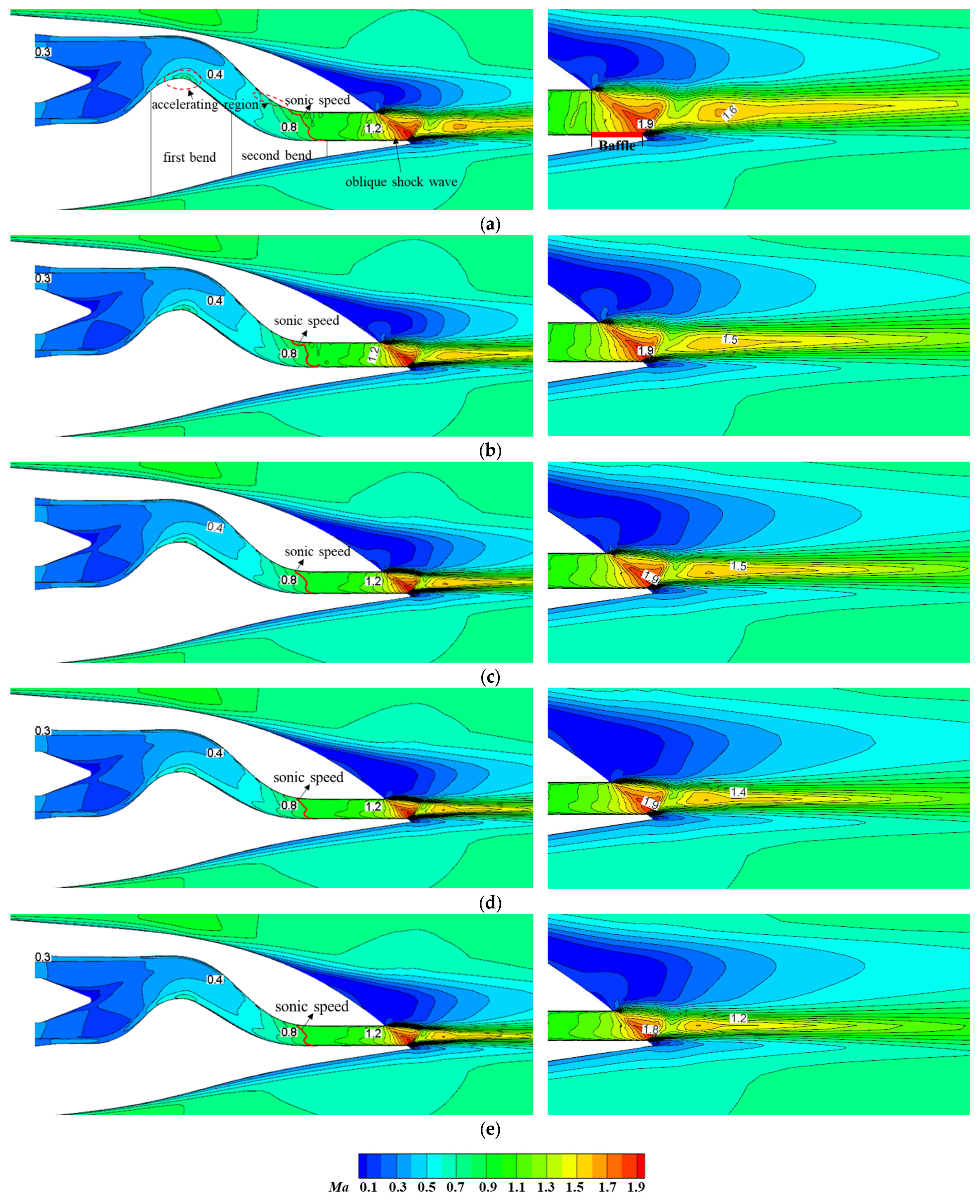
Figure 6 shows the
Ma distribution on the symmetrically cut plane of the whole aircraft assembled with serpentine nozzles of different outlet aspect ratios. For the serpentine configuration, the flow field inside the nozzle is asymmetric. There is a local accelerating region near the lower wall of the first bend and the upper wall of the second bend (indicated by the red dashed box). The internal flow first accelerates to supersonic speed at the upper wall of the second bend, forming a locally inclined and curved sonic speed surface (indicated by the red curve), and eventually reaches the maximum velocity and generates an oblique shock wave at the nozzle outlet. Due to the integrated conformal design of the nozzle and the aircraft, the length of the upper wall at the nozzle outlet is shorter than that of the lower wall, which corresponds to the existence of a baffle (indicated by the thick red line). Such a lower baffle causes the tail jet to only expand unilaterally upward, resulting in the thrust of the nozzle deflecting upwards. The interaction between the high-speed tail jet and the separated flow of the afterbody induces a distinct shear layer structure. The velocity of the tail jet exhibits the intermittent Mach wave, characteristic of “high-low-high” speed. Due to the complete expansion of the outlet flow, the detached tail jet no longer expands, and continues to mix with the afterbody external flow, resulting in a gradual decrease in the velocity of the tail jet. Since the differences in the profiles between the serpentine nozzles with different aspect ratios are mainly located at the second S-bend runner (
Figure 5), the variation in
AR has less influence on internal flow at the first S-bend runner and its upstream area, and thus the corresponding distribution of
Ma is basically the same. Once the flow enters the second S-bend runner, the difference in the internal flow field caused by the increase in
AR gradually amplifies, e.g., the degree of the bending and inclination of the sonic speed surface reduces. As
AR increases, the longitudinal offset of the nozzle profile decreases while the transverse expansion increases, resulting in a decrease in the longitudinal curvature and an increase in the transverse curvature at the second bend runner. This, in turn, slows down the internal flow acceleration near the upper wall of the second bend and shrinks the accelerating region. The increase in the wetted circumference causes a larger shear area between the high-speed tail jet and the external flow, leading to an increase in the mixing loss as well as the energy loss of the tail jet. The length of the tail jet is shortened, and the intensity of the shock wave is weakened. In addition, with the increase in
AR, the outlet height decreases, and the length difference between the upper and lower wall of the nozzle outlet decreases. Therefore, the degree of upward unilateral expansion of the tail jet is weakened. The region of the afterbody separating flow gradually increases, while the external flow has no significant effect on the tail jet.
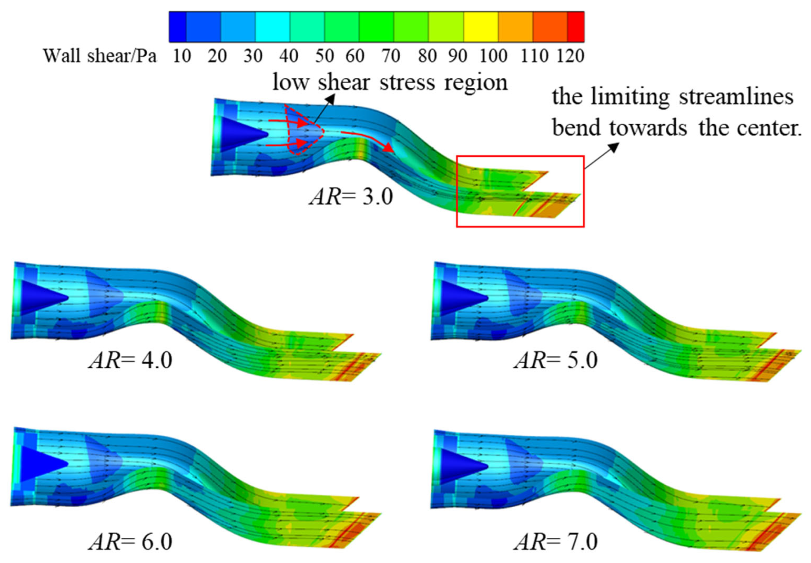
The distribution of limiting streamlines and wall shear stresses on the surface of the nozzle with different
AR is shown in
Figure 7. With the transition of the runner cross-section from circular to square, a low wall shear stress region exists in the center region of the square runner (indicated by the red dashed area), where the central shear stress is smaller than that of surrounding area, causing the limiting streamlines to bend towards the center. At the second S-bend runner, the wall shear stress on the upper and lower wall outside is larger than that of the center, leading to the convergence of the limiting streamlines on the upper and lower walls at the straight section towards the center. The longitudinal deflection characteristic of the nozzle causes the limiting streamlines on the side wall to bend accordingly, leading to a sharp increase in wall shear stress on the inner wall located at the bend region. Therefore, the limiting streamlines on the side wall of the equal straight section deflect downwards. As
AR increases, the transverse expansion of the nozzle profile increases while the longitudinal deflection decreases. The wall shear stresses gradually become uniform. Thus, the transverse deflection of the limiting streamlines of the upper and lower wall surfaces increases, but the longitudinal bending decreases. Moreover, the reduction in longitudinal deflection weakens the internal flow accelerating effect near the lower wall of the first bend and the upper wall of the second bend, and reduces the corresponding wall shear stress.
The increase in
AR weakens the accelerating effect of the internal flow, resulting in a decrease in the longitudinal deflection of the internal flow. The wall shear stress on the lower wall of the first bend and the upper wall of the second bend gradually decreases, thereby reducing the friction loss, local acceleration loss, and collision loss in the corresponding areas. However, the larger the
AR, the larger the wetted area of the internal flow runner, and the stronger the transverse expansion of the internal flow, resulting in greater friction losses. Therefore, the friction loss of the nozzle needs to comprehensively consider the above two factors.
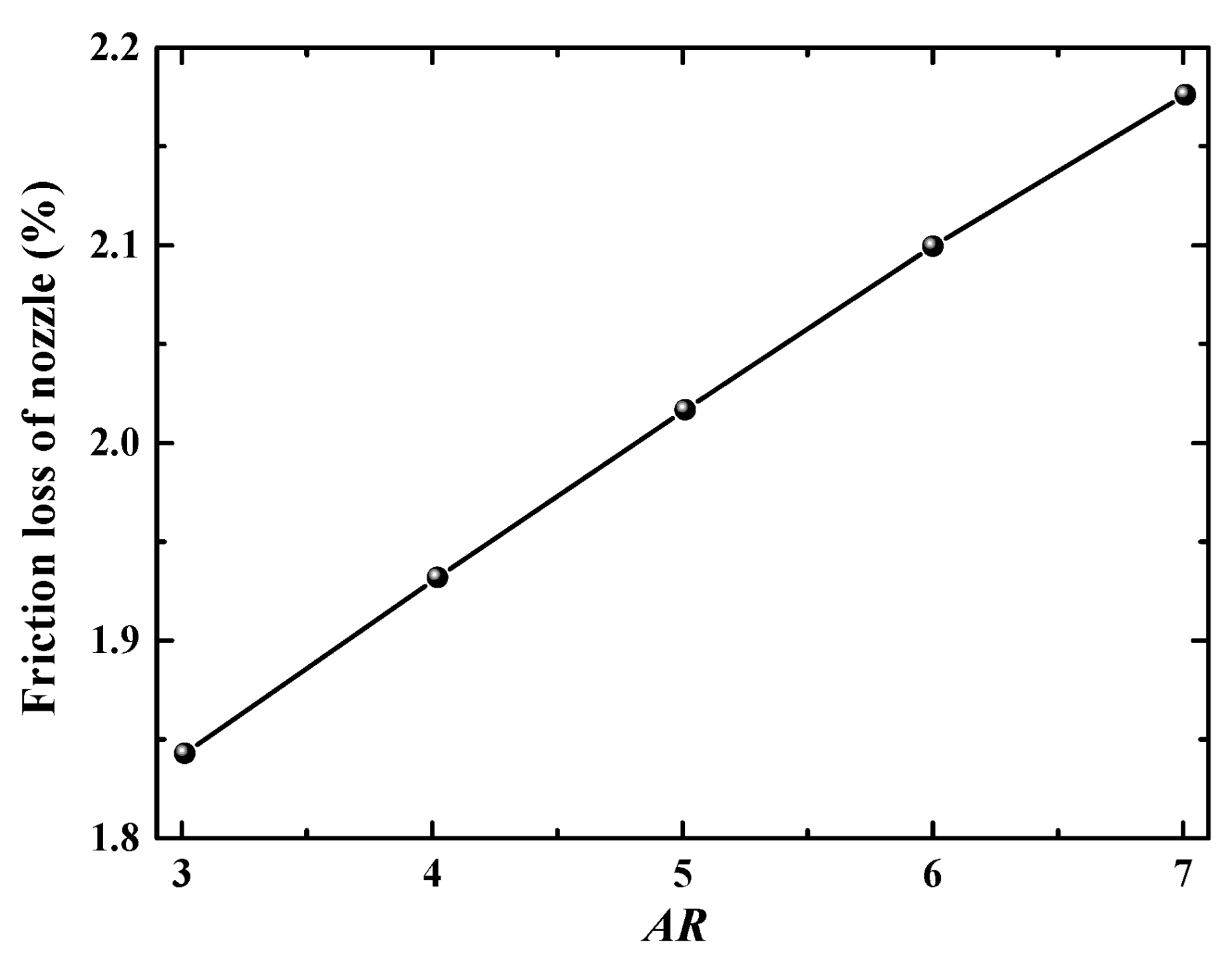
Figure 8 shows the effect of
AR on the friction loss of the nozzle. As
AR increases, the friction loss increases linearly, indicating that the increase in the
AR weakens the aerodynamic performance of the serpentine nozzle.
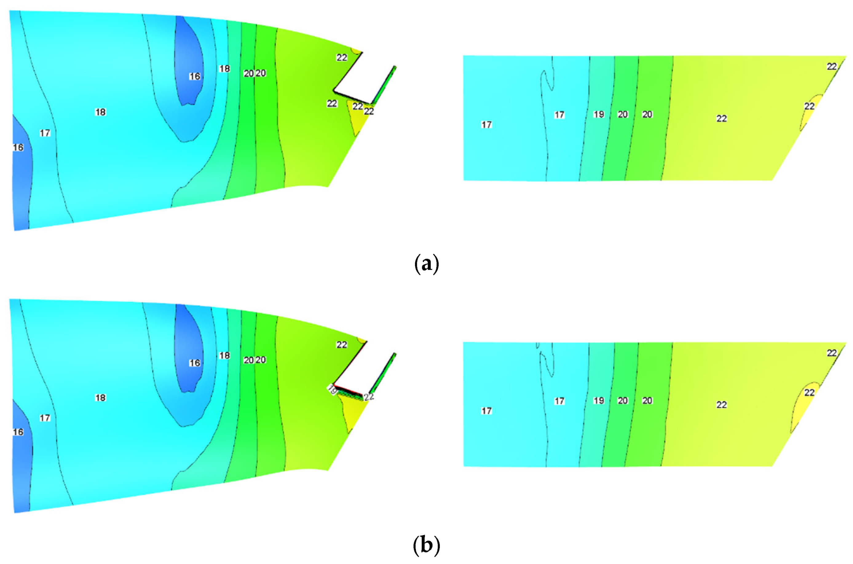
To further explore the impact of internal and external flow coupling on the aircraft afterbody, the pressure distribution on the upper and lower surfaces of the afterbody under different
AR is shown in
Figure 9. The upper surface pressure increases gradually along the flow, then drops sharply at the boundary layer separation point, but finally increases continuously. This is because the afterbody surface converges rapidly after the separation point, and the sudden expansion of the subsonic external flow runner causes the external flow to slow down, thereby causing the surface pressure to increase along the way. However, in the region near the nozzle outlet, a low-pressure region is formed due to the unilateral expansion of the internal flow. The lower surface pressure of the afterbody increases uniformly along the way, and is less affected by the internal flow of the nozzle. The variation in
AR only affects the pressure distribution near the nozzle outlet of afterbody. With the increase in
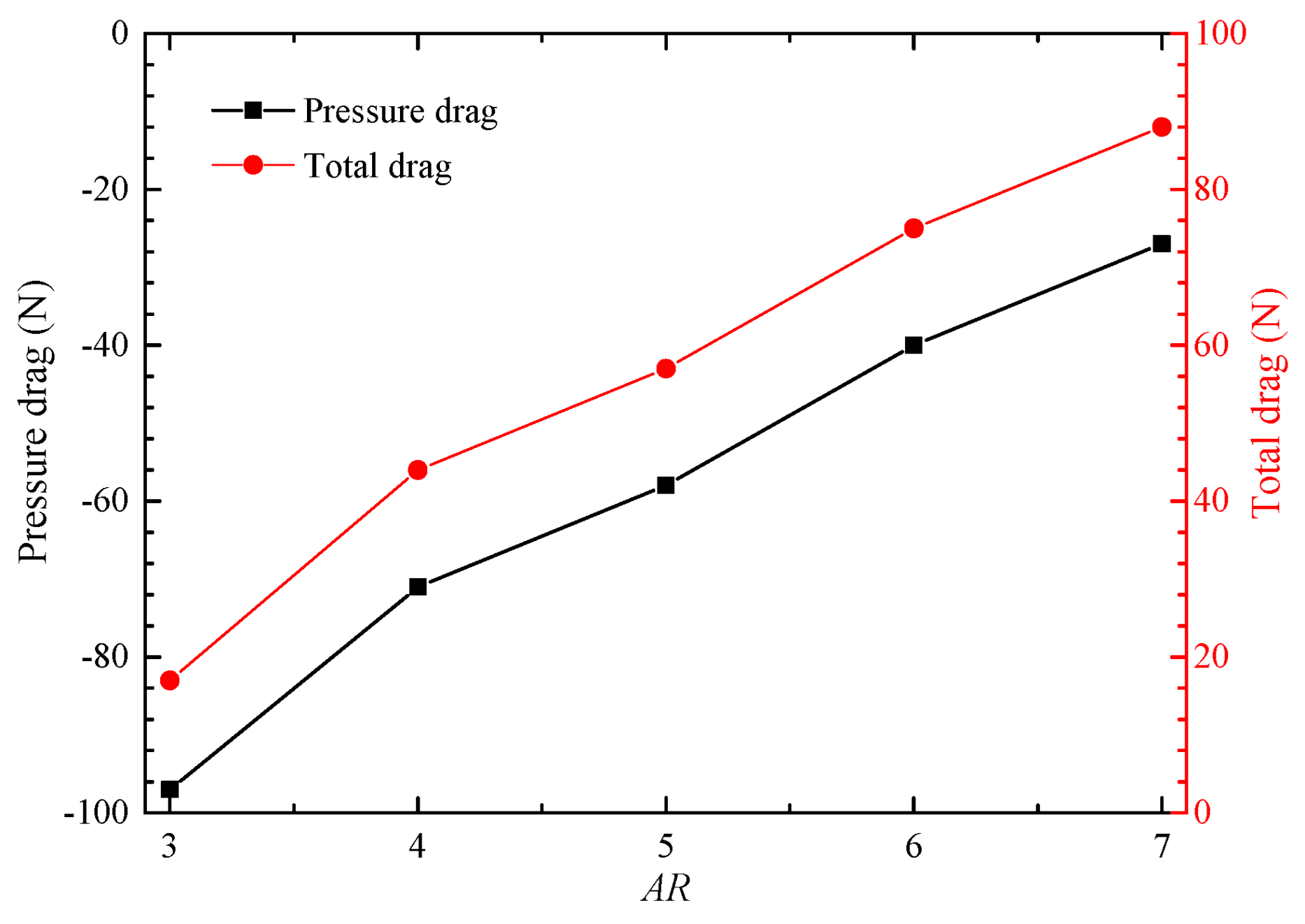
AR, the wetted circumference of the internal flow runner becomes longer, and the low-pressure region near the nozzle outlet expands, which increases the pressure difference drag of the afterbody. As a result, the total drag of the afterbody increases, and thus the aerodynamic performance of the aircraft is reduced, as shown in
Figure 10.
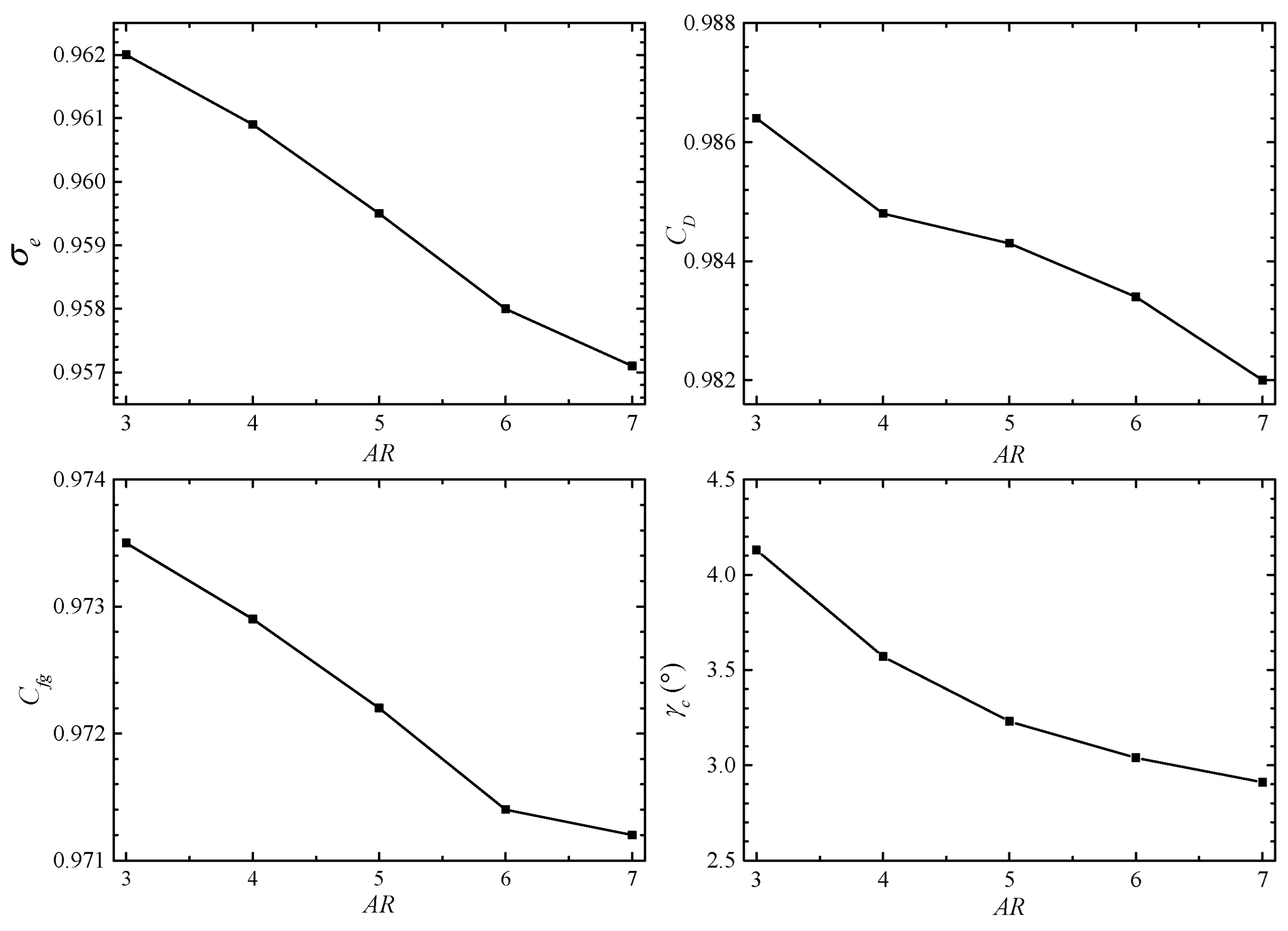
Figure 11 analyzes the influence of
AR on the aerodynamic performance of the serpentine nozzle. The total pressure recovery coefficient, flow coefficient, axial thrust coefficient and thrust vectoring angle all decrease with the increase in
AR. The increase in
AR increases the wetted area of the internal flow runner, which increases the friction loss, thereby reducing the aerodynamic performance of the nozzle. However, the increase in
AR weakens the accelerating effect of internal flow, reducing the wall shear stress at the bend area. The friction loss, local acceleration loss, and collision loss in the corresponding region decrease, and thus enhance the aerodynamic performance of the nozzle. These two have opposite effects on the aerodynamic performance of the nozzle, and the degree of weakening is stronger (
Figure 8). It ultimately induces a reduction in the total pressure recovery coefficient, flow coefficient, and axial thrust coefficient. Compared with
AR = 3, the total pressure recovery coefficient, flow coefficient and axial thrust coefficient of the
AR = 7 nozzle decreased by 0.51%, 0.45% and 0.24%, respectively. The thrust vector angle of the nozzle is mainly determined by the degree of the uneven longitudinal expansion of the tail jet. The length of the lower baffle at the nozzle outlet shortens as
AR increases, which reduces the upward unilateral expansion nonuniformity of the tail jet (
Figure 6), resulting in a decrease in the thrust vector angle.
3.2. Effect of LDR on the Interaction between the Nozzle Flow and External Flow
The
LDR of the serpentine nozzle directly affects the longitudinal turning and lateral expansion of the internal flow runner, which changes the flow characteristics of the nozzle flow, and in turn affects its aerodynamic performance. To this end, under the constraints of equal inlet and outlet areas and complete shielding (
SR = 1) design criteria, five different serpentine nozzles with different
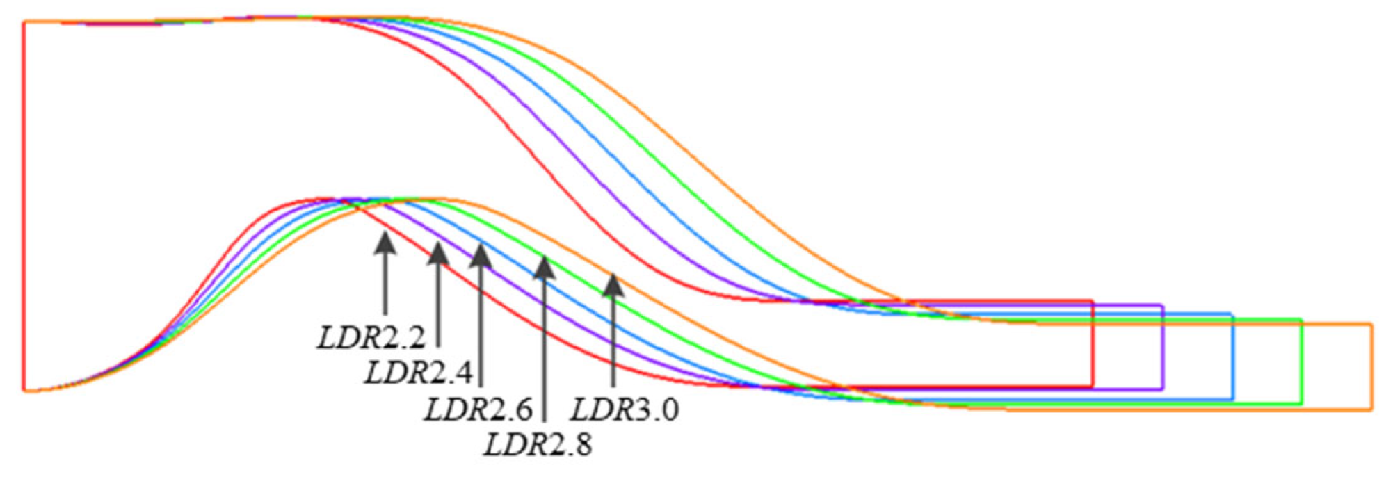
LDR (=2.2, 2.4, 2.6, 2.8, 3.0,
AR = 6.0) are constructed, as shown in
Figure 12. As
LDR increases, the length of the nozzle increases, and the curvature at the first and second bends decreases, resulting in a slower longitudinal deflection and lateral expansion of the internal flow runner, but the longitudinal offset of the nozzle outlet slightly increases.
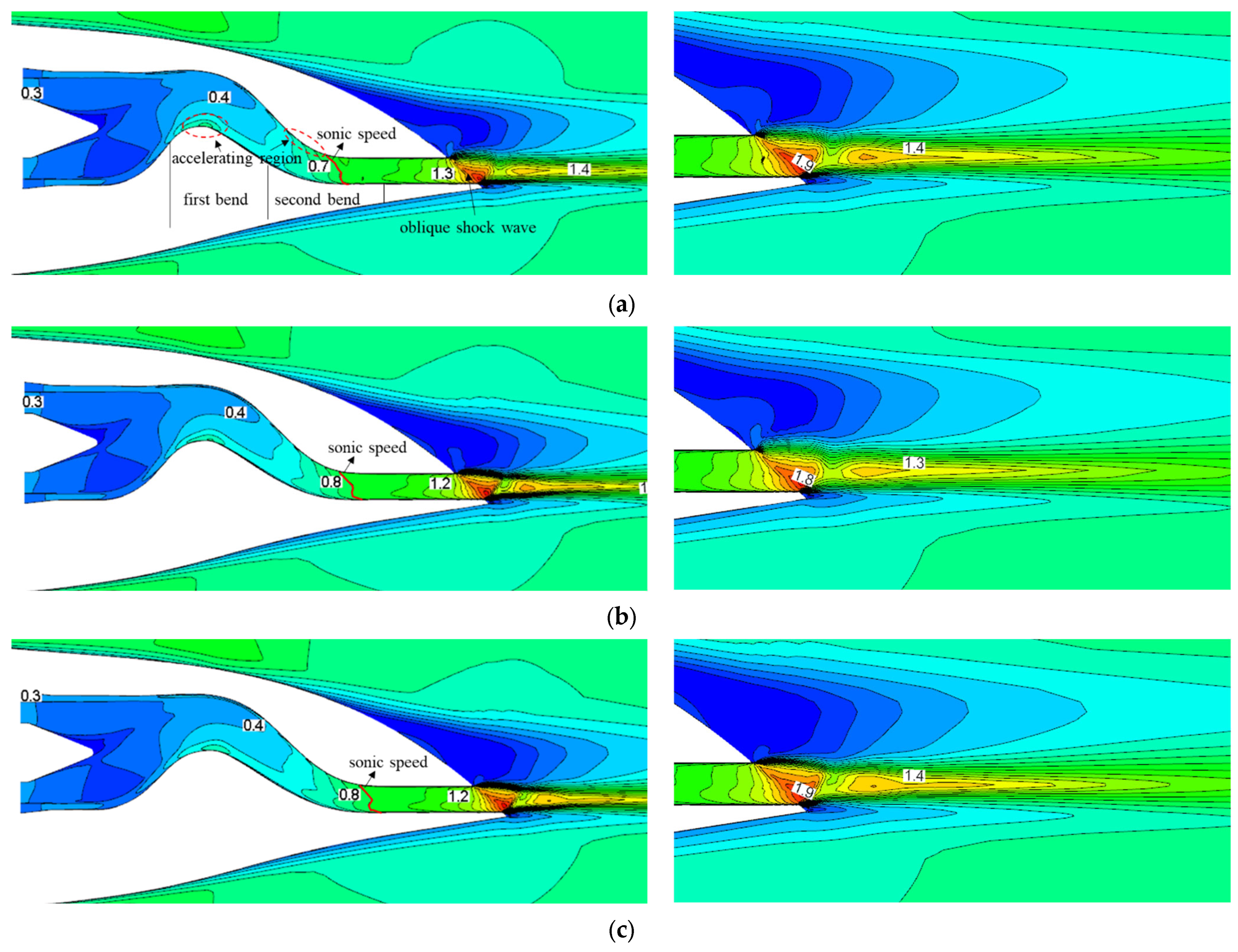
Figure 13 illustrates the Mach number distribution on the symmetric cut plane of the aircraft equipped with nozzles of different
LDR. The flow field inside the nozzle exhibits an asymmetric configuration, wherein the internal flow accelerates continuously along the convergent runner. The flow reaches the sonic speed near the second S-bend, forming a left-inclined sonic speed surface, and finally accelerates to the maximum velocity at the nozzle outlet. As
LDR increases, the curvature of the internal flow runner slows down, resulting in a decrease in the local accelerating effect of the flow at the bends, as well as a decrease in the accelerating region and flow velocity within the accelerating region. However, the Mach number distribution at the nozzle outlet remains unaffected by the variation in
LDR. Notably, the nozzle outlet profile and assembly position remain unchanged, thereby having no significant impact on the interaction between the nozzle flow and external flow.
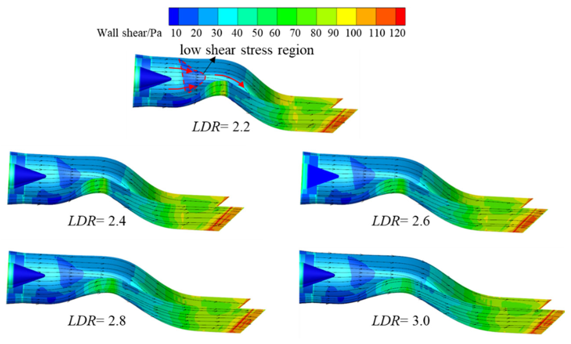
Figure 14 shows that the wall shear stress along the runner shows an increasing trend, and reaches a maximum value at the nozzle outlet. Meanwhile, the variation in the internal flow direction caused the local wall shear stress near the lower wall of the first bend and the upper wall of the second bend to increase significantly. The increase in
LDR induces the longitudinal deflection and lateral expansion of the internal flow runner to slow down, resulting in the weakening of the local accelerating effect at the two bends and a reduction in the local acceleration loss. Furthermore, as
LDR increases, the shear stress at the lower wall of the first bend and the upper wall of the second bend gradually decreases, which reduces the friction loss and collision loss in the corresponding areas. However, the longer the length of the serpentine nozzle, the larger the wetted area of the internal flow, which leads to the increase in friction loss along the runner. The combined effect of these causes the internal flow friction loss to increase with the increase in
LDR, as shown in
Figure 15.
Figure 16 displays the surface pressure distribution on the afterbody of aircraft equipped with serpentine nozzles with different
LDR. The upper surface pressure increases gradually along the external flow direction, and then rises rapidly after a sudden drop near the separation point, reaching the maximum near the nozzle outlet, while the lower surface pressure increases continuously along the external flow direction. Since the nozzle outlet profile and assembly position are independent of
LDR, the Mach number distribution of the nozzle tail jet under different
LDR is also similar (
Figure 13), and the difference in
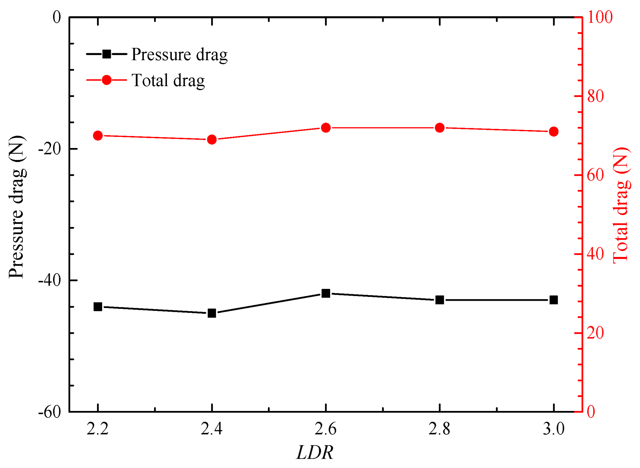
LDR has no significant effect on the surface pressure distribution on the afterbody of the aircraft. Therefore, the pressure drag and total drag of the afterbody are slightly changed with the increase in
LDR, as shown in
Figure 17.
The increase in
LDR leads to an increase in internal flow friction loss (
Figure 15), and the increase in longitudinal offset will cause an increase in nozzle flow resistance. Although the longitudinal deflection and lateral expansion of the internal flow runner become slower, reducing the impact loss and acceleration loss at the bends, the degree of flow deterioration is stronger, resulting in a decline in the aerodynamic performance of the nozzle, as shown in
Figure 18. With the increase in
LDR, the total pressure recovery coefficient, flow coefficient and axial thrust coefficient all decrease slightly, while the thrust vector angle remains constant. Compared with
LDR = 2.2, the total pressure recovery coefficient, flow coefficient and axial thrust coefficient of the
LDR = 3.0 configuration are reduced by 0.21%, 0.41% and 0.13%, respectively, indicating that the variation in
LDR has little effect on the aerodynamic performance of the serpentine nozzle.
3.3. Effect of SR on the Interaction between the Nozzle Flow and External Flow
The shielding rate of the serpentine nozzle determines the degree of exposure of the high-temperature components of the aircraft, and has an important impact on the infrared radiation intensity of the high-temperature wall and the aircraft tail jet. To explore the influence of
SR on the interaction between the nozzle flow and external flow, five nozzles with different
SR (=0, 0.25, 0.5, 0.75, 1.0,
AR = 6.0,
LDR = 2.6) are adopted, as shown in
Figure 19. The change in
SR is mainly realized by modifying the profile of the second S-bend runner. The higher the
SR, the greater the offset of the nozzle outlet, and the greater the longitudinal curvature of the second S-bend.
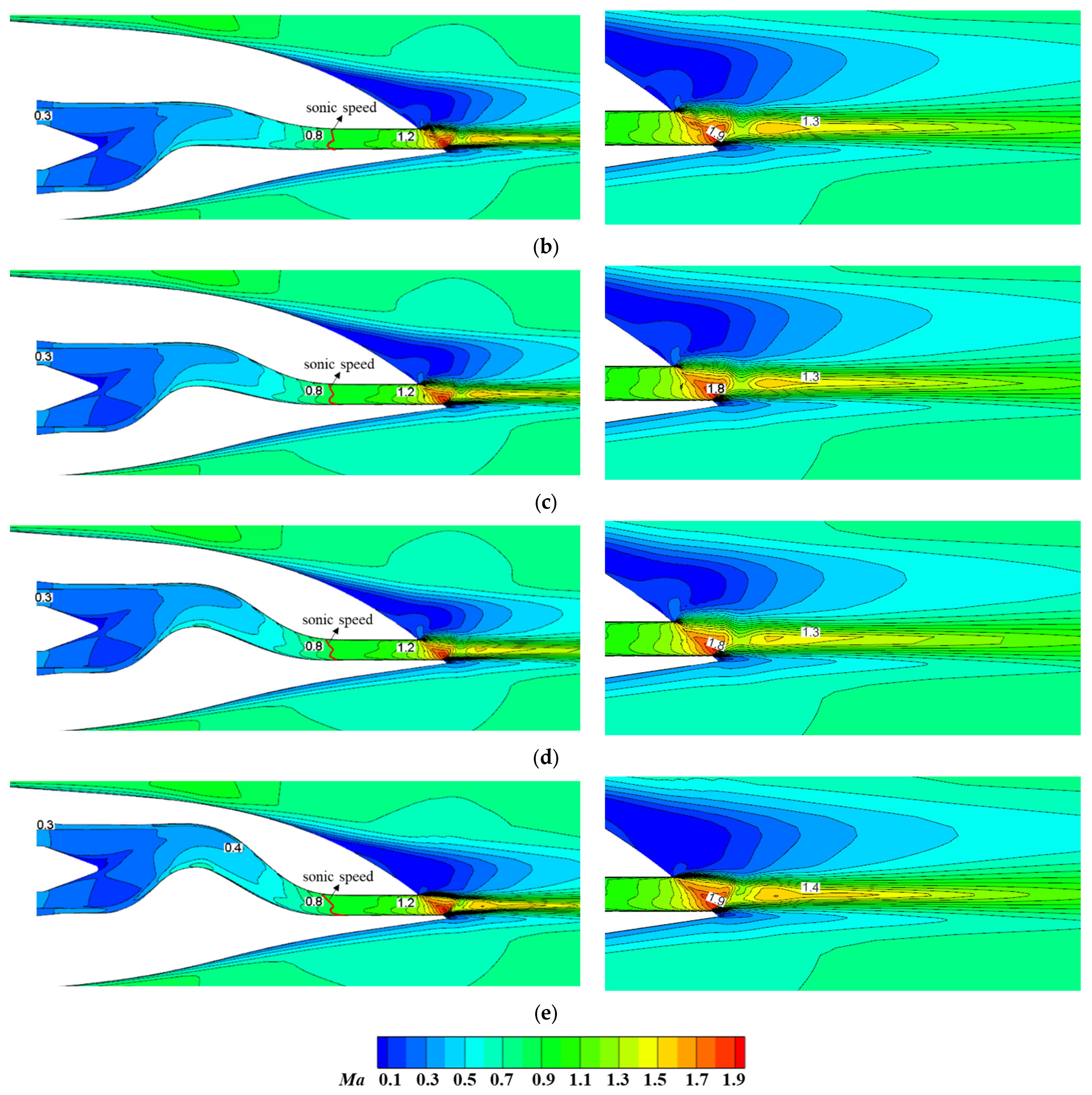
Figure 20 depicts the Mach number distribution on the symmetry cut plane of the aircraft under different
SR. For
SR = 0, the runner behind the first S-bend is a rectangular convergent nozzle, and the internal flow continues to accelerate until the velocity in the straight section reaches the sonic speed. The Mach number contour at the second S-bend shows a rightward inclination trend, with the degree of leftward inclination decreasing as it approaches the nozzle outlet, and eventually an oblique shock wave is formed at the outlet. The tail jet expands unilaterally upward because of the lower baffle at the outlet, and mixes with the separated external flow around the afterbody, producing significant interference shock waves and shear layer structures. As
SR increases, the curvature of the second S-bend increases gradually, as well as the accelerating effect near the upper surface of the second S-bend. The accelerating region also expands gradually, inducing the gradual leftward inclination of the Mach number contour at the nozzle outlet. However, due to the consistent geometric characteristics of the nozzle outlet, the Mach number distribution tends to be similar within the straight section, and the corresponding flow characteristics of the tail jet are also similar.
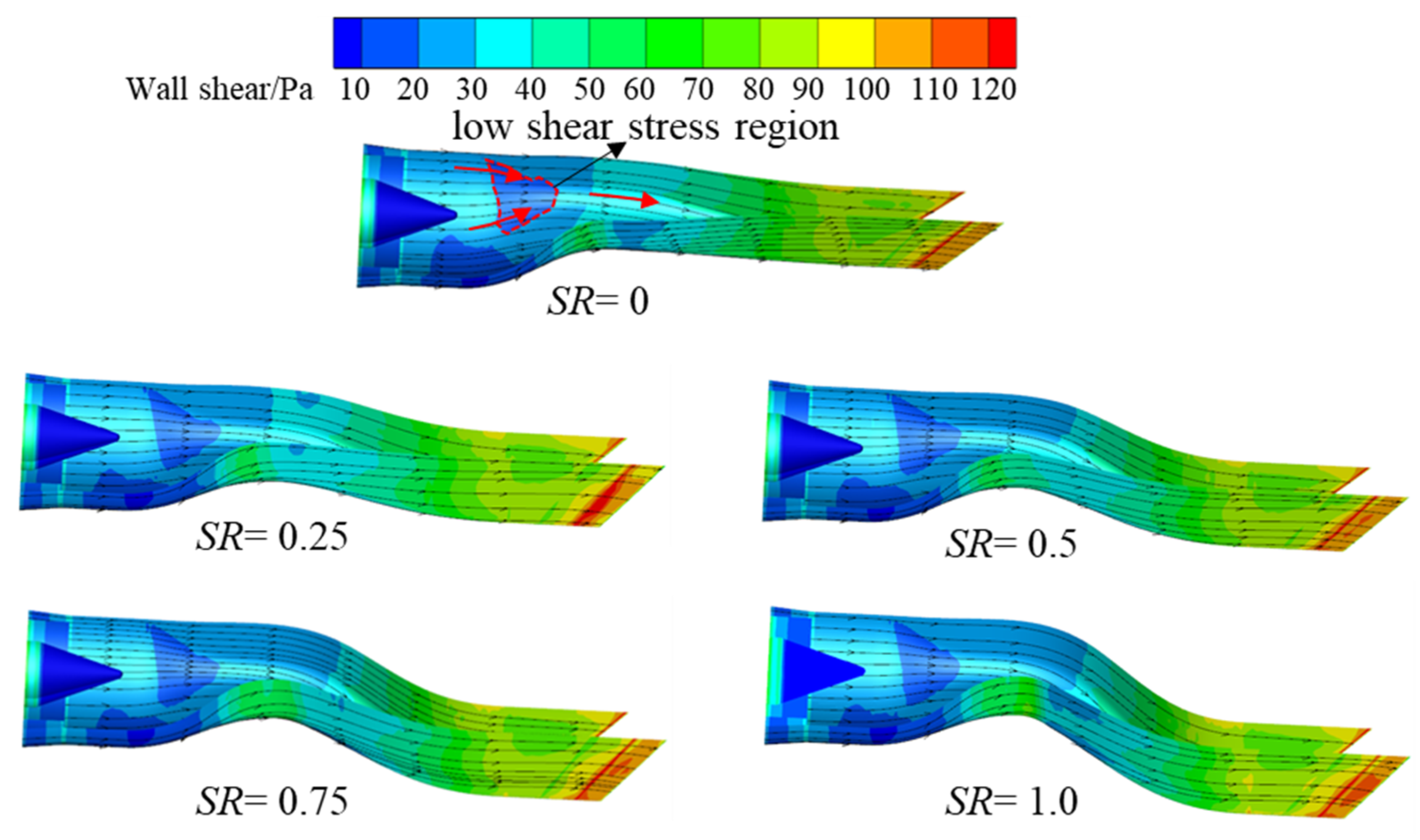
Figure 21 shows the distribution of wall shear stress and the limiting streamline on the nozzle wall under different
SR. For
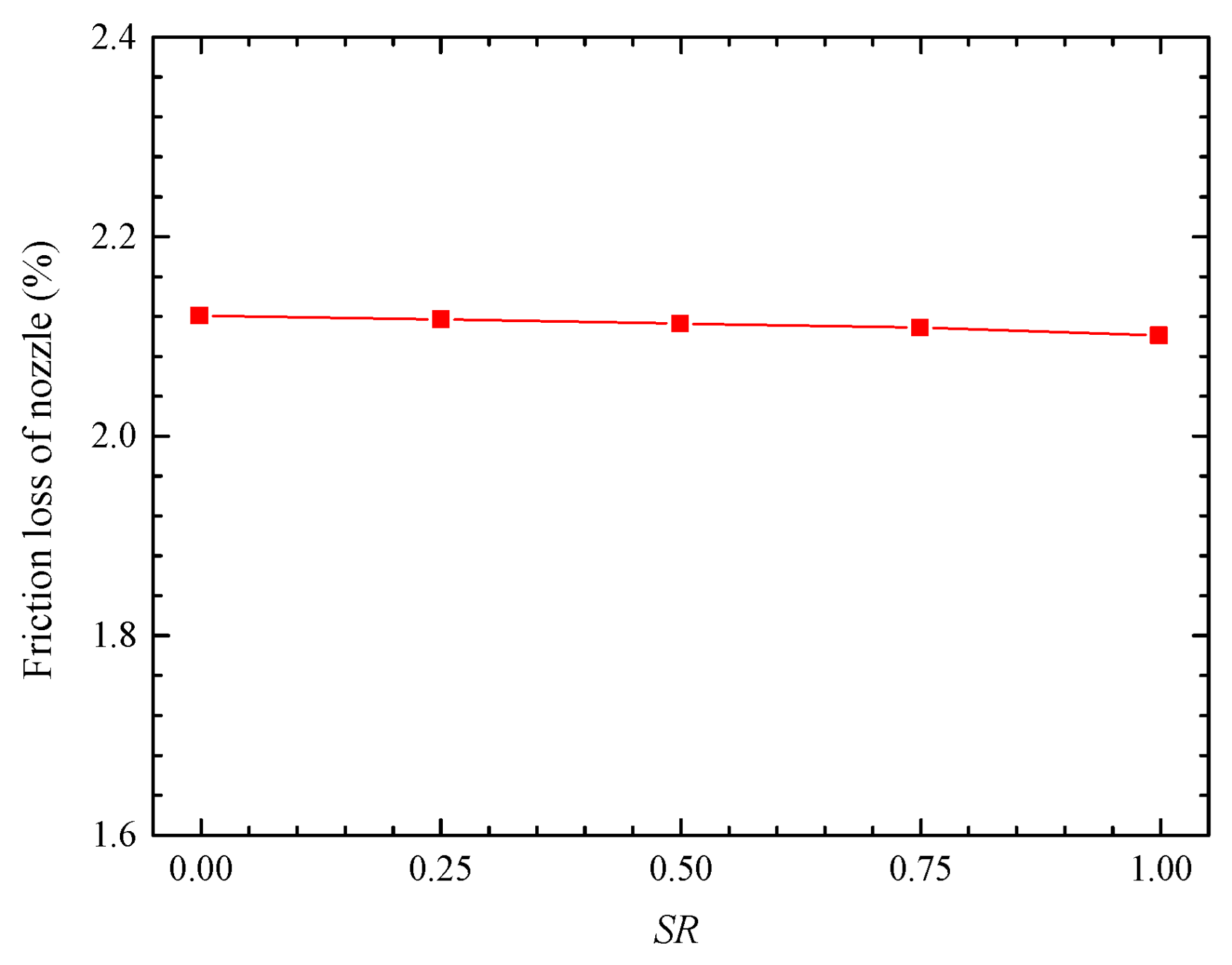
SR = 0, the wall shear stress tends to increase along the nozzle flow, but a local high wall shear stress zone appears near the lower wall of the first S-bend. With the increase in the second S-bend curvature, the longitudinal bending degree of the limiting streamline increases, and the limiting streamline at the equal straight section gradually closes inward. With the increase in shielding ratio, the wall shear stress located at the lower wall of the first S-bend and the upper wall of the second S-bend gradually increases, which leads to the increase in the local friction loss. Furthermore, although the
LDR of nozzles with different
SR is equal, the length of the nozzle flow runner becomes slightly longer as the
SR increases, which causes the wetted circumference area to increase, leading to the increase in friction loss. However, the wall shear stress on upper wall of the second S runner generally decreases, which reduces the friction loss in this area. These two factors have opposite effects on nozzle friction loss, and the influence degree is similar, which eventually leads to a slight change in nozzle flow friction loss, as shown in
Figure 22.
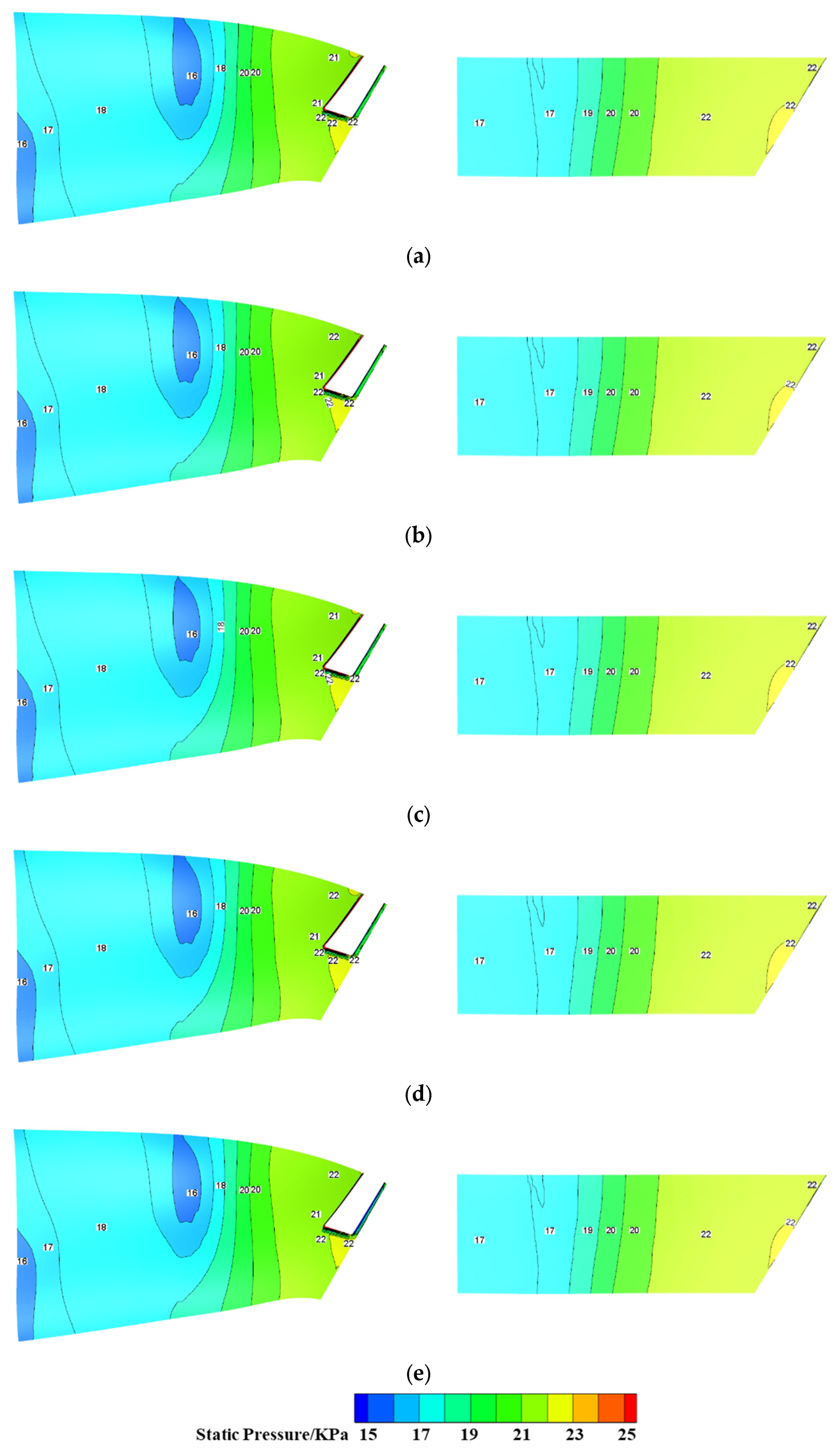
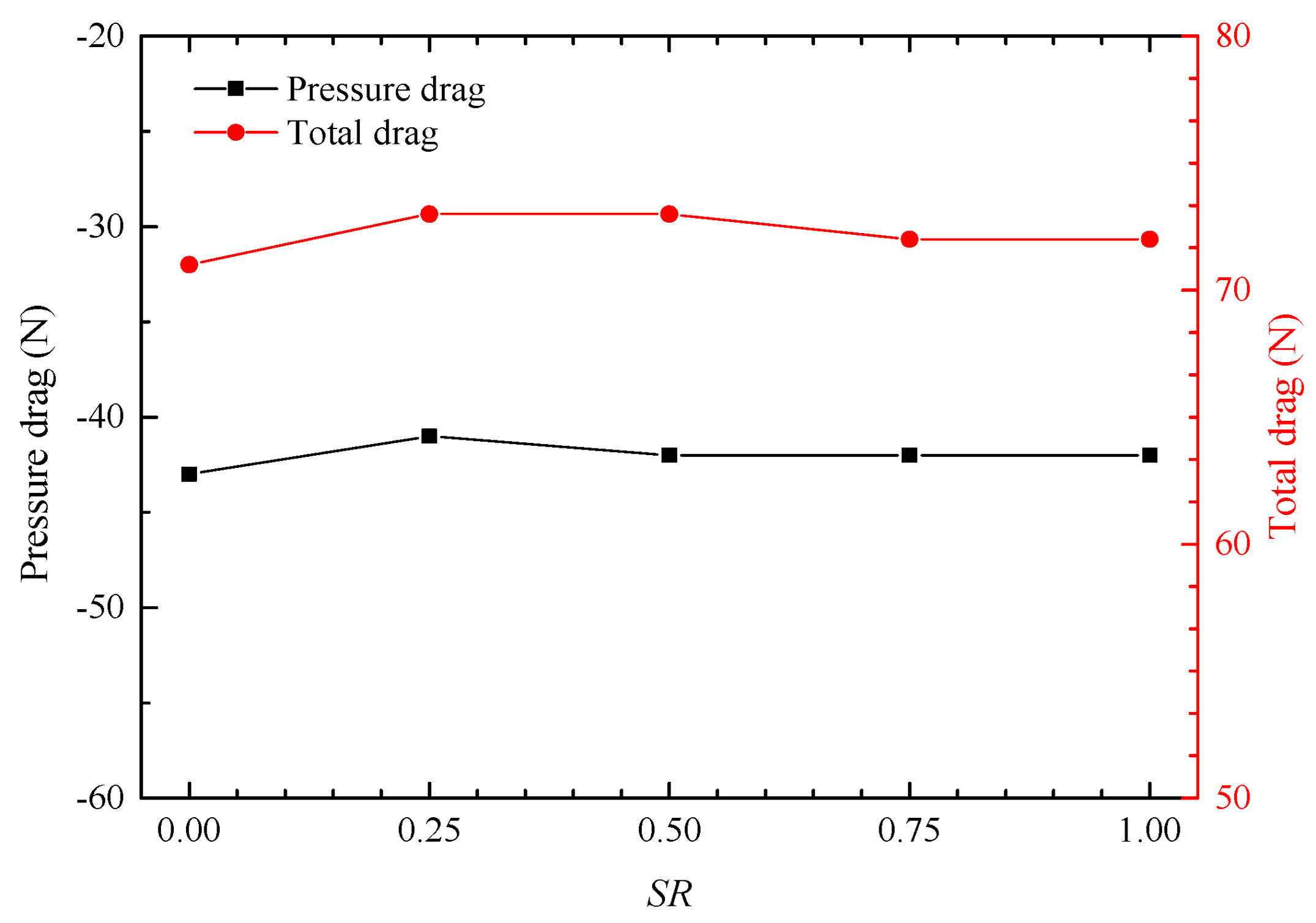
Figure 23 depicts the influence of
SR on the surface pressure distribution of the afterbody. Due to the similarity in the flow characteristics of tail jets (
Figure 20), the surface pressure distribution of the afterbody is basically the same under different
SR, so the pressure drag and total drag of the afterbody change slightly (
Figure 24), indicating that the variation in
SR has slight influence on the aerodynamic characteristics of the afterbody.
As the
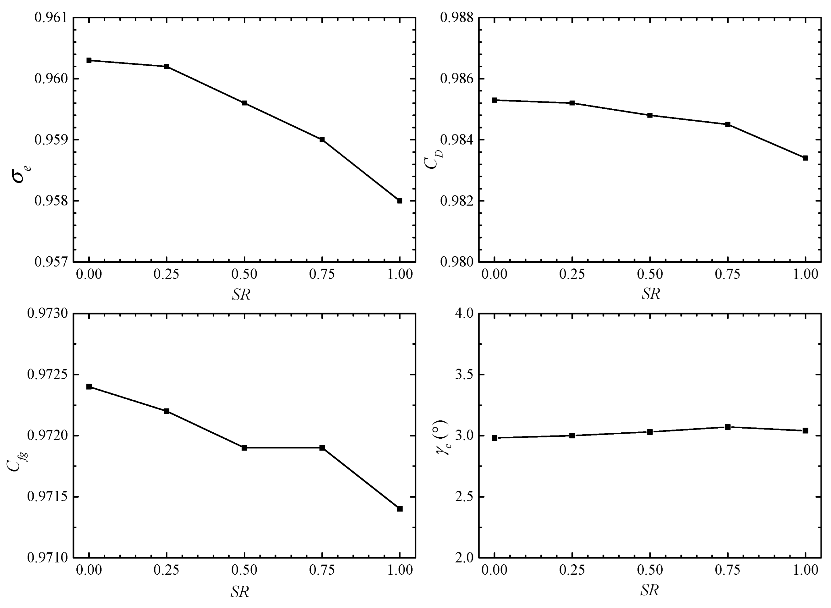
SR increases, the curvature of the second S-bend increases, which leads to the strengthening of the flow accelerating effect at the bend and the expansion of the accelerating region. Meanwhile, the local collision loss and acceleration loss increase, while the friction loss along the route is almost unchanged (
Figure 22). Therefore, the aerodynamic performance decreases. The total pressure recovery coefficient, flow coefficient and axial thrust coefficient all decrease with the increase in
SR, as shown in
Figure 25. Compared with the non-shielded nozzle (
SR = 0), the total pressure recovery coefficient, flow coefficient and axial thrust coefficient of the fully shielded nozzle (
SR = 1) decreased by 0.24%, 0.19%, and 0.10%, respectively. However, the thrust vector angle is almost constant, which is independent of
SR.
