Article

Data-Driven-Method-Based Guidance Law for Impact Time and Angle Constraints

by
Wenjie Cao
1,
Jia Huang
2 and
Sijiang Chang
1,*
1
School of Energy and Power Engineering, Nanjing University of Science and Technology, Nanjing 210094, China
2
Nanjing LES Information Technology Co., Ltd., Nanjing 210014, China
*
Author to whom correspondence should be addressed.
Aerospace 2024, 11(7), 540; https://doi.org/10.3390/aerospace11070540
Submission received: 24 May 2024 / Revised: 27 June 2024 / Accepted: 28 June 2024 / Published: 1 July 2024
(This article belongs to the Special Issue Dynamics, Guidance and Control of Aerospace Vehicles)

Abstract

:
To increase the hit efficiency and lethality of a flight vehicle, it is necessary to consider the vehicle’s guidance law concerning both impact time and angle constraints. In this study, a novel and straightforward impact time and angle control guidance law that is independent of time-to-go and small angle approximations is proposed with two stages using a data-driven method and proportional navigation guidance. First, a proportional navigation guidance-based impact angle control guidance law is designed for the second stage. Second, from various initial conditions on the impact angle control guidance simulation with various initial conditions, the input and output datasets are obtained to build a mapping network. Using the neural network technique, a mapping network model that can output the ideal flight path angle in flight is constructed for impact time control in the first stage. The proposed impact time and angle control guidance law reduces to the proportional navigation guidance law when the flight path angle error converges to zero. The simulation results show that the proposed guidance law delivers excellent performance under various conditions (including cooperative attack) and features better acceleration performance and less control energy than does the comparative impact time and angle control guidance law. The results of this research are expected to supplement those exploring various paradigms to solve the impact time and angle control guidance problem, as concluded in the current literature.

1. Introduction

With the development of advanced precision-guided flight vehicles, defense systems have also been developed accordingly in recent years. Under these circumstances, it is becoming increasingly difficult for a single flight vehicle to break through a defense system. To increase the hit efficiency and lethality of a flight vehicle, launching a saturation attack by using multiple flight vehicles simultaneously is a feasible approach. For this purpose, imposing terminal constraints on the design of flight vehicle guidance laws is effective. Initially, only the impact angle constraint was considered [1,2], and the corresponding guidance was called impact angle control guidance (IACG). A flight vehicle controlled via the IACG law can strike its target with an expected line-of-sight angle, increasing the effectiveness of warheads. In 2006, a guidance law that considers the impact of time constraints was first proposed by [3]. This law is called impact time control guidance (ITCG). The ITCG law can be implemented by a flight vehicle to strike a target at a desired impact time. Subsequently, the impact time and angle control guidance (ITACG) law was developed by [4] in 2007 to simultaneously satisfy these two constraints (e.g., for a salvo attack).
Although many investigations of IACG have been performed in recent decades, several novel studies have been published in recent years. Lee and Seo [5] analyzed the actual physical meaning of the IACG law from the optimal guidance perspective to provide a deeper understanding. By using optimal control theory and optimal error dynamics, Li et al. [6] proposed an IACG law that can address large initial heading errors. Several other researchers have focused on the application of practical theories. For instance, Lin and Xin [7] presented a unified applicability analysis pertinent to IACG using the state-dependent Riccati equation. In [8], the observability of the target is considered, and a predefined time error dynamic was used to design a three-dimensional IACG in [9].
Relatively, the number of investigations on pure ITCG has exceeded that on IACG in recent years (i.e., as of 2016). In this period, two kinds of theories and techniques, namely the sliding mode control (SMC) theory and the shaping technique, were widely used in designing specific ITCG laws. For instance, an effective nonsingular sliding mode guidance that addresses the impact time constraint was proposed in [10]. Chen and Wang [11] designed an SMC-based ITCG law with a field-of-view constraint without using time-to-go estimation or the small-angle assumption. In [12], the nonsingular SMC theory was also used to design an ITCG law that can address various target motions. For the application of the shaping technique, a quartic range shaping-based ITCG law was proposed in [13] and subsequently extended to the generalized form in [14]. Subsequently, Tekin et al. [15,16] proposed a polynomial look angle shaping method that can be used to design ITCG laws and performed an in-depth study. In [17], circular impact time guidance was proposed by virtue of the geometrical principle that constrains the interceptor to follow a circular trajectory to the target. Moreover, the application of feedback linearization [18], proportional navigation guidance (PNG) [19,20], and differential geometric guidance strategies [21] in the design of ITCG laws has also been explored in recent years.
Compared to the individual ITCG or IACG, the design of ITACG is obviously more difficult. To satisfy both the impact time and angle constraints, the whole design is usually divided into two steps. First, the guidance law for one constraint is designed, after which the guidance law for the other constraint is constructed. When certain approaches (e.g., optimal control theory) are applied to the design of an ITACG, two steps may sometimes turn into an integrated form. Because the investigation of ITCG and IACG is the foundation of ITACG, many theories or techniques that are used for ITCG and IACG can also be applied to ITACG, such as biased proportional navigation guidance (BPNG), sliding mode control theory, shaping technique, optimal control theory, and combined approaches.
To exploit the advantages of PNG, Zhang et al. [22,23] proposed a BPNG-based ITACG that comprises pure PNG and an additional biased term. For the application of SMC theory, Harl and Balakrishnan [24] proposed a robust second-order SMC law to track the desired line-of-sight rate profile. Kumar and Ghose [25] designed an ITACG law according to an SMC-based ITCG law by considering the curvature of the trajectory. Zhao et al. [26] applied the time-varying sliding mode technique to fulfill these impact constraints. In [27], a nonsingular terminal SMC-based ITACG law was proposed in which two different terminal sliding mode surfaces were designed to control the impact time and angle simultaneously. Chen and Wang [28] designed an SMC-based ITACG law that is not based on time-to-go error regulation or parameter tuning and can address disturbances (e.g., autopilot lag). Liu and Li [29] presented an ITACG law by using the adaptive SMC method and derived an adaptive law to adjust the guidance gain. Recently, cooperative guidance for multiple flight vehicles with impact time and angle constraints in three-dimensional space was widely investigated by using fixed-time sliding mode surfaces [30,31] or integral global sliding mode control techniques [32].
Moreover, numerous studies on the use of the shaping technique in ITACGs have been conducted. Kim et al. [33] proposed a polynomial function of the guidance command with three unknown coefficients that are determined to satisfy the impact time and angle constraints. Zhao et al. [34] applied the trajectory reshaping technique to an ITACG and consequently obtained a specific polynomial function with unknown coefficients. Tekin et al. [35] proposed an ITACG law based on look-angle shaping via time-dependent polynomials developed in [15,16] and subsequently extended it for moving targets [36]. In [37], a guidance strategy that can track a time-varying look angle was proposed and applied to the ITACG problem. By developing a dynamic line-of-sight shaping technique (i.e., shaping various Bezier curves), Catak and Emre [38] discussed an ITACG law in which the guidance command has a form of biased PNG.
Within the nonlinear optimal control framework, the guidance command is usually the optimal solution of the ITACG problem. In [4], an ITACG law with a feedback loop and an additional control command was proposed according to the optimal control theory. By constructing an optimal guidance problem with an endpoint cost aimed at extremizing the impact time and angle, an optimal-solution-based ITACG was derived in [39]. Lee and Kim [40] introduced a virtual target. Therefore, the ITACG problem was formulated as a two-point boundary value problem (TPBVP). By solving this TPBVP, the ITACG command can be obtained. Another way to apply optimal control theory is demonstrated. As shown in [41,42,43], only the impact-angle-constrained optimal guidance law was derived and solved. The impact time constraint was simultaneously satisfied by designing a feedback controller in [41] and by adding an additional maneuvering acceleration term in [42], whereas impact time control was achieved using a state-variable-shaped impact time profile in [43].
To make full use of each theory or technique, previously mentioned theories or techniques have also been combined to study the ITACG law in several current research studies. Usually, the guidance procedure is explicitly divided into two stages or parts. For instance, in [44,45], the SMC theory was used in the first stage, and the PNG theory was used in the second stage. PNG can also be employed for the first stage, as shown in [46,47]. For the second stage or part, an energy optimal guidance law was derived in [46], and the maneuvering flight was utilized in [47]. A two-stage ITACG law that comprises a nonsingular SMC-based guidance law for the first stage and a switching target strategy for the second stage was proposed in [48]. Additionally, the look-angle-shaping technique and the SMC method were combined to design the ITACG law with a field-of-view constraint in [49], achieving accurate performance.
Several other theories or techniques have also been applied to the study of ITACG in recent years. By using the geometric principle of trajectory (e.g., log-aesthetic space curve, collision line, circle involute, and deviated pure pursuit) [50,51,52,53,54], effective and robust ITACGs can be obtained. In addition, a three-dimensional vector guidance law was first developed, and the corresponding ITACG law was subsequently proposed by adding a time-to-go feedback term [55]. A cooperative flight vehicle thrust control law was incorporated into a modified PNG-based IACG law [56], achieving a multi-flight vehicle salvo attack with impact time and angle constraints.
Despite the abovementioned great progress in the investigation of ITACGs achieved in recent years, the ITACG problem remains a largely open and non-trivial challenge because of increasingly complicated nonlinearity and multiple constraints. The existing methods or strategies for accessing ITACGs have their own limitations. It is necessary to introduce more advanced techniques or theories to address the ITACG problem. In recent years, with the prevalence of data-driven methods, an advanced and powerful research tool has been developed for aeronautics and aerospace engineering [57,58,59,60,61,62]. Compared to traditional methods, artificial neural networks (ANNs) (i.e., one of the most important data-driven methods) are much more suitable for addressing complicated nonlinear problems due to their advanced nonlinear fitting and generalizability. Li et al. [63] introduced a so-called wavelet neural network to the design of the SMC-based IACG law, aiming to reduce high-frequency chattering of acceleration guidance commands. By building a database offline with the input of a flight state vector and the output of PNG time-to-go, Guo and Li et al. [64] developed a novel data-driven ITCG model considering both kinematics and dynamic effects. As shown in [64], the database is utilized directly in the guidance procedure without any surrogate models. A preliminary application of a data-driven method in the ITACG problem, as reported in [65], was discussed by using an ANN. However, in both [64,65], computing time-to-go is necessary.
Although the data-driven method has been widely applied in various industrial fields and has demonstrated significant potential, overall, the corresponding applications in the ITACG problem in the current research literature are insufficient. The major difficulty or challenge is determining how to set a reasonable and feasible application paradigm for a specific problem or object. The main motivation for the results of this paper came from [64,65], where the authors successfully incorporated the data-driven method into the design of ITCG and ITACG. For the sake of practical engineering, several limitations, such as the requirement of time-to-go, need to be overcome. For this purpose, new application procedures need to be established. In this paper, an IACG guidance law is designed based on the proportional guidance law. On this basis, combined with the data-driven method, an ITACG guidance law that does not depend on the remaining flight time is developed. Like many studies on ITACG, the proposed guidance law is also divided into two stages. In the second stage, the impact angle is controlled within the framework of PNG. The desired impact angle is reversely considered one of the conditions for achieving impact time control in the first stage, where a novel mapping relationship is constructed. The main contributions of this paper can be summarized as follows:
  • By drawing on a large number of related studies, such as the effective use of PNG [19,20,22,23,44,45,46,47,56,64,65], PNG is applied to data-driven ITACG design. Compared with other literature, it not only retains the advantages of PNG but also has a simple structure, does not require small angle assumption, and does not need the remaining flight time information.
  • A new paradigm is developed for the data-driven method, and a new time-independent ITACG law is designed. Compared with the existing literature [28], the guidance law has less overload in the guidance process, less control energy consumption, strong adaptability, and high precision.
This paper is organized as follows. We first describe the equations of motion in Section 2. In Section 3, we evaluate a pure IACG law as a predesign. Afterward, in Section 4, we design an ITACG law by using the data-driven method and derive specific guidance commands. In Section 5, we provide and subsequently discuss the simulation results of the proposed IACG, ITACG, and cooperative attack for multiple flight vehicles. Finally, in Section 6, we present concluding remarks.

2. Problem Description and General Scheme

2.1. Equations of Motion for Engagement

The problem studied in this paper is parallel to that presented elsewhere (see, e.g., [4] and the references therein). To ensure completeness, this section aims to introduce the necessary notations and equations used in subsequent sections. We consider a two-dimensional engagement scenario between a flight vehicle and a stationary target, as shown in Figure 1. The assumptions are as follows:
  • The flight vehicle is considered a point mass.
  • Only the normal acceleration perpendicular to the velocity vector of the flight vehicle is considered.
  • The autopilot lag is neglected.
The equations of motion are expressed as follows:
R ˙ = V cos φ
m V ˙ = P X m g sin λ
θ ˙ = ( V sin φ ) / R
γ ˙ = a m / V
φ = γ θ
where R is the distance between the flight vehicle and the target; m is the mass of the flight vehicle; V is the speed of the flight vehicle; P is the thrust force; X is the drag force; g is the acceleration of gravity; θ is the line-of-sight angle; γ is the flight path angle; φ denotes the heading error; a m is the normal acceleration of the flight vehicle (which is perpendicular to the flight vehicle’s velocity vector); and the dot over the variant denotes the first derivative with respect to time t. Thus, θ ˙ is the line-of-sight rate.
It is obvious that, when the flight vehicle hits the target accurately with the expected impact time t d and desired impact angle θ d , the following conditions are satisfied:
R ( t f ) = 0 ,   t f = t d ,   θ f = θ d
where t f denotes the actual impact time when the flight vehicle hits the target and θ f represents the impact angle when the flight vehicle hits the target (in this paper, it is expressed by the terminal line-of-sight angle).

2.2. General Scheme for ITACG Design

In the framework of PNG, the factors that affect the impact time and angle control are associated with the heading error, implying that the impact time and angle constraints can be obtained by controlling the heading error. However, the heading error that satisfies the impact time constraint is usually different from that for impact angle control. Therefore, the proposed guidance procedure is divided into two stages, and as a result, impact time control and impact angle control are achieved in succession. Due to the relationship between the heading error and the flight path angle, as shown in Equation (5), the heading error control can be transformed to flight path angle control. Correspondingly, the flight path angle that satisfies these two constraints can be called the ideal flight path angle γ d . Hence, obtaining γ d is the key point in controlling the impact time and angle.
In this paper, we first consider impact angle control in the second stage. With the help of the PNG technique, an IACG law is developed by converging the error of the flight path angle (i.e., between the ideal and actual flight path angles at the same time). Since impact angle control is realized in the second stage, the expected impact angle is known when we address the impact time control subsequently. Therefore, in the first stage, the flight state variables that affect the impact time are ( R , θ , γ , θ d ) , and there exists an explicit mapping P t between the impact time t f and ( R , θ , γ , θ d ) [65], i.e.,
t f = P t ( R , θ , γ , θ d )
Obviously, when the flight path angle γ in Equation (7) is the ideal angle γ d , the mapping (7) can be rewritten as
t d = P t ( R , θ , γ d , θ d )
According to the mapping relationship (8), an implicit mapping P γ pertinent to the ideal flight path angle γ d and flight state variables can be expressed as
γ d = P γ ( R , θ , t d , θ d )
Notably, the time t d in Equation (9) can be understood as the expected time-to-go, assuming that the initial time is zero. In the case of arbitrary time t s during flight, the mapping relationship shown in Equation (9) also holds, and the expected time-to-go at arbitrary time t s is ( t d t s ) . In other words, the desired impact time t d in mapping (9) can be replaced by the expected time-to-go ( t d t s ) . Thus, for any moment t s , the corresponding ideal flight path angle γ ds can be determined as follows:
γ ds = P γ s ( R s , θ s , t d t s , θ d )
where R s and θ s represent the distance and the line-of-sight angle at t s , respectively, and P γ s denotes the corresponding mapping that will be constructed by the neural network, as shown in later sections.
By comparing the ideal flight path angle with the actual flight path angle at arbitrary time t s , the error in the flight path angle can be defined as follows:
ε = γ ds γ s
where γ s denotes the actual flight path angle at t s .
It is obvious that impact time control can be realized in the first stage as long as the error ε is reduced to zero within a finite time. Thus, the key to converging the flight path angle error lies in determining the ideal flight path angle. In this effort, a data-driven method is used to address the mapping relationship to obtain the ideal flight path angle at any time during the flight vehicle’s flight (see Section 4). The following content of this article includes a pure IACG law as a predesign (used for the second stage) and, thereafter, the design of the ITACG law.

3. Predesign: A Pure Impact Angle Control Guidance Law

In this section, we intend to design a pure impact angle control guidance law as the predesign of the impact time and angle control guidance law. Although this IACG law is used in the second stage, from a design perspective, it is considered the basis of the design of the ITCG in the first stage as well as the comprehensive ITACG, providing known information and required datasets.

3.1. Theoretical Analysis

In the two-dimensional scenario, to simplify the derivation process, it is assumed that, in Equation (2), the thrust, drag, and gravity forces acting on the aircraft balance each other out, which means that the velocity of the missile remains constant, denoted as V m . Hence, the guidance command according to the proportional navigation guidance law can be expressed as follows:
a m = N V m θ ˙
where N denotes the guidance gain. Its selection directly affects the characteristics of the flight vehicle and determines its ability to hit the target. Therefore, it is crucial to consider not only the flight vehicle’s characteristics but also its structural strength and the guidance system’s stability. It is generally accepted that the value of N is usually in the range of 3 to 6. For our model, we select N = 3 .
The rate of change in the flight path angle under the framework of PNG is expressed as
γ ˙ = N θ ˙
The relationship between the change rate of the heading error and the change rate of the line-of-sight angle can be obtained from Equations (5) and (13), as follows:
φ ˙ = ( N 1 ) θ ˙
Under the framework of PNG, the heading error converges to zero at the final time t f , i.e.,
φ 0 + 0 t f φ ˙ ( t )   d t = 0
where φ 0 is the initial heading error.
When the initial line-of-sight angle is θ0, the terminal line-of-sight angle θ f at t f can be written as
θ f = θ 0 + 0 t f θ ˙ ( t )   d t = θ 0 + 1 N 1 0 t f φ ˙ ( t )   d t = θ 0 φ 0 N 1
When considering N = 3 , the terminal line-of-sight angle θ f can be expressed as
θ f = θ 0 φ 0 2
According to Equations (5) and (17), the relationship between the terminal line-of-sight angle θ f and the initial flight path angle γ0 can be obtained as follows:
θ f = 3 θ 0 γ 0 2
To ensure that the terminal line-of-sight angle meets the constraints of the impact angle, the following formula with respect to the initial flight path angle should hold when the initial line-of-sight angle is considered constant:
γ 0 = 3 θ 0 2 θ d
At any time of flight t s for a flight vehicle, the terminal line-of-sight angle can be written as follows:
θ f = θ s φ s 2
where θs and φ s denote the line-of-sight angle and the heading error at t s , respectively.
Therefore, for an arbitrary moment of flight t s , to ensure that the terminal line-of-sight angle meets the constraints of the impact angle without changing the line-of-sight angle, the ideal flight path angle for the IACG (denoted as γ ds IACG ) should be expressed as
γ ds IACG = 3 θ s 2 θ d
In the next section, this ideal flight path angle for the IACG is used to design the guidance command for impact angle control.

3.2. Guidance Command for Impact Angle Control

By using the pure proportional navigation guidance law, when the desired impact angle is given, the ideal flight path angle γ ds IACG that meets the impact angle constraint at any time can be obtained from Equation (21). The error between the ideal flight path angle γ ds IACG and the actual flight path angle γs at the same moment is defined as
ξ = γ ds IACG γ s
If this error can be eliminated before hitting the target and then adopting the pure PNG law, impact angle control can be realized. Therefore, before implementing the pure navigation guidance law, an impact angle control guidance law should be designed to correct the flight path angle and eliminate errors ξ .
Equation (3) shows that the rate of change in the flight path angle γ ˙ is related to the acceleration a m . Thus, the following mathematical relationship holds:
γ ˙ = a m / V m = ξ ˙
To ensure that the change in the acceleration meets the requirements of continuity and smoothness, the flight path angle error ξ is assumed to converge to zero smoothly. Therefore, a mathematical relationship relating the flight path angle error ξ to the rate of change in the flight path angle error ξ ˙ is established as follows:
ξ ˙ = k 2 tanh ( ξ )
where tanh (   ) is the hyperbolic tangent function for which the definition is tanh ( x ) = ( e x e x ) / ( e x + e x ) , and k 2 is a positive number that is used to adjust the convergence rate of ξ . Notably, the subscript “2” of k 2 represents the second stage.
By substituting Equation (24) into Equation (23), the guidance command of impact angle control can be obtained as
a m = k 2 V m tanh ( ξ )
When the flight path angle error ξ is eliminated, the expected impact angle can be achieved by using pure PNG. Notably, after the error ξ converges to zero, the guidance command of impact angle control will become zero and remain unchanged. In this case, an offset term of the pure PNG with N = 3 is added to the guidance command given in Equation (25). Thus, a modified guidance command is obtained as follows:
a m IACG = 3 V m θ ˙ + k 2 V m tanh ( 3 θ 2 θ d γ )
The effectiveness of the proposed guidance command (26) is validated in the simulation section, and it is also demonstrated that this IACG law is adaptive to conditions with varying velocities.

3.3. Stability and Convergence Analysis

This section comprises an analysis of the stability and convergence of the proposed IACG law by using Lyapunov theory. The error ξ is taken as the variable, and the following Lyapunov candidate function is chosen:
V ( ξ ) = 1 2 ξ 2
Taking the first derivative of Equation (27) with respect to time yields
V ˙ ( ξ ) = ξ ξ ˙
Substituting Equation (24) into Equation (28) yields
V ˙ ( ξ ) = k 2 ξ tanh ( ξ )
Because both k 2 and ξ tanh ( ξ ) are greater than zero, V ˙ ( ξ ) is negative definite. As a result, the Lyapunov stability criterion is satisfied. Moreover, it is proven that the flight path angle can converge to the ideal flight path angle under the control of the guidance command, which means that impact angle control can be realized. For this purpose, the differential relationship between the flight path angular error and the time is written as
d ξ ( t ) d t = k 2 tanh ( ξ )
Integrating the flight path angle error yields the following:
ξ 0 ξ ( t ) e ξ + e ξ e ξ e ξ   d ξ = 0 t k 2   d t
where ξ 0 denotes the initial error of the flight path angle.
Solving Equation (31) yields the following:
ξ ( t ) = ln ( δ + δ 2 + 1 )
where δ = ( 1 / 2 ) | e ξ 0 e ξ 0 | e k 2 2 t .
In essence, ξ ( t ) is an inverse hyperbolic sine function and an odd function that increases monotonously, while δ has a lower bound and decreases monotonously in the interval t [ 0 , + ) . Therefore, ξ ( t ) also has a lower bound (i.e., the lower bound is zero) and decreases monotonically in t [ 0 , + ) . In addition, the convergence rate of ξ ( t ) is faster when the value of k increases, and vice versa.
Because ξ 0 < 2 π , ξ ( t ) satisfies the following inequality:
ξ ( t ) < ln ( π e k 2 2 t + π 2 e k 2 t + 1 )
Regarding the function of the right-hand side of Equation (33), the convergence rate is affected by the value of k 2 . For instance, when k 2 = 1 and t = 20   s , ξ ( t ) < 1.43 × 10 4 holds; and when k 2 = 2 and t = 20   s , ξ ( t ) < 1.00 × 10 8 holds. It can be speculated that the flight path angle error converges to zero during a certain period, and more importantly, the convergence rate can be controlled by the parameter k 2 .

4. Design of the Impact Time and Angle Control Guidance Law

In this section, based on the predesigned IACG law presented in Section 3, a detailed design of the ITACG law is provided in terms of the general scheme described in Section 2.2. By virtue of the artificial neural network technique, an application paradigm of the data-driven method is proposed to construct the mapping relationship (10) and then determine the ideal flight path angle γ ds during the flight vehicle’s flight.

4.1. Application Paradigm of an ANN

For the mapping relation P γ s shown in Equation (10), a specific application paradigm is developed, and a corresponding surrogate model is established by using the artificial neural network (ANN) technique [66]. The ANN technique is widely used in many academic and industrial fields due to its strong capability for nonlinear fitting and generalization. Because the ANN technique has been studied or introduced in many textbooks and papers, the detailed principle and algorithm of ANNs are not described in this paper. The specific steps for generating the ANN-based surrogate model that corresponds to the mapping relationship P γ s are described as follows:
Step (i): According to the explicit mapping shown in Equation (7), the values of the flight state variable ( R , θ , γ , θ d ) are set within their own ranges and combined into the initial condition dataset of the simulation.
Step (ii): Using the IACG law as presented in Section 3, a series of simulations for impact angle control are performed for all the initial conditions in the dataset. For each simulation, the values of the flight state variables ( R , θ , γ , θ d ) with corresponding time of flight t (i.e., the expected time-to-go) are recorded.
Step (iii): Considering the simulated values of ( R , θ , t , θ d ) as the input dataset S 1 ( R , θ , t , θ d ) and the simulated values of γ as the output dataset S 2 ( γ ) , the training datasets S 1 ( R , θ , t , θ d ) and S 2 ( γ ) are obtained based on the simulation results.
Step (iv): Using the training datasets S 1 ( R , θ , t , θ d ) and S 2 ( γ ) , an ANN-based surrogate model is trained offline via the backpropagation approach. As a result, the model yields the mapping network with respect to γ and ( R , θ , t , θ d ) , which corresponds to Equation (9) as follows:
γ = N e t γ ( R , θ , t , θ d )
where N e t γ ( ) represents the mapping network (surrogate model) of the flight path angle in the impact time control stage.
Step (v): According to Equation (10), the mapping network of the ideal flight path angle at arbitrary time t s that corresponds to P γ s can be obtained as follows:
γ ds ITCG = N e t γ ( R s , θ s , t d t s , θ d )
where γ ds ITCG denotes the ideal flight path angle at arbitrary time t s in the impact time control stage.
Due to the features of ANNs, once the training of the mapping network (usually performed offline) is completed, it is efficient to obtain the output data with specific input data. In the abovementioned paradigm, the state variables ( R s , θ s , t d t s , θ d ) are assumed to be known (can be measured/determined online in practical engineering) during the process of engagement, and the corresponding ideal flight path angle can be calculated using the cost-effective ANN-based surrogate model.

4.2. Guidance Command for Impact Time and Angle Control

By using the data-driven method, the error between the ideal and actual flight path angles in the first stage can be obtained. Thus, Equation (11) can be rewritten as follows:
ε = γ ds ITCG γ
It is obvious that if the error ε can be eliminated within a finite period, the expected impact time can be achieved. In this section, the approach presented in Section 3 is used to eliminate the error ε and design the guidance commands for both the impact time and angle control.
Like in Equation (23), the following equation also holds:
γ ˙ = a m / V m = ε ˙
Thus, the rate of change in the error ε can be designed as follows:
ε ˙ = k 1 tanh ( ε )
where k 1 is a small number greater than zero, which is used to adjust the error convergence rate of the first-stage trajectory inclination angle (e.g., k 1 = 0.1 ).
By substituting Equations (36) and (38) into Equation (37), the guidance command for impact time control can be expressed as
a m ITCG = k 1 V m tanh ( γ ds ITCG γ )
When the flight path angle error ε converges to zero, the impact time control stage (the first stage) ends, and the impact angle control stage (the second stage) begins. To avoid excessive changes in acceleration caused by guidance commands during the transition from the first stage to the second stage, a modification to Equation (39) should be considered. By using a method that is identical to that of Equation (26), the guidance command in Equation (39) is modified as follows:
a m ITCG = 3 V m θ ˙ + k 1 V m tanh ( γ ds ITCG γ )
The abovementioned procedure shows that the proposed guidance command for ITCG does not require time-to-go. Thus, the goal of eliminating the dependence of PNG on the estimated time-to-go is achieved.
Combined with Equation (26), novel two-stage guidance commands for both impact time and angle control can be obtained as follows:
a m = { 3 V m θ ˙ + k 1 V m tanh ( γ ds ITCG γ ) γ ds ITCG γ σ   3 V m θ ˙ + k 2 V m tanh ( 3 θ 2 θ d γ ) γ ds ITCG γ < σ  
where k 2 is a small number greater than zero, which is used to adjust the error convergence rate of the second-stage trajectory inclination angle. σ represents the switching condition of the guidance command, which is a small number tending to zero. The smaller the value of σ is, the higher the control precision. This allows for the actual trajectory inclination angle to infinitely approach the ideal trajectory inclination angle, thus transforming impact time control into impact angle control (e.g., σ = 0.001 ).
The specific value of γ ds ITCG in Equation (41) is determined by using the neural network model in Equation (35) during flight. Notably, the essence of the first stage is to make the actual flight path angle γ gradually approach the ideal flight path angle γ ds ITCG when controlling the impact time. As the error of the flight path angle converges to zero, impact time and angle control are realized by the action of PNG, implying that the proposed ITACG law has good engineering practicability. Moreover, the stability and convergence of the proposed ITCG strategy (the first expression in Equation (41)) can also be analyzed by using the same approach as that presented in Section 3.3. For brevity, the analysis process is not covered in this section.

5. Simulation Results

To validate the proposed ITACG law, several numerical simulations are performed with previously derived equations. Because the two-stage ITACG law (41) involves the IACG law (26), the effectiveness of the IACG law is validated first in Section 5.1, where simulations are conducted with different initial conditions for a variety of desired impact angles. In Section 5.2, the proposed ITACG is validated considering the variety of expected impact times and angles. In particular, the process of building a specific mapping network is included in this section as well as a comparative study and a simulation of cooperative attacks for multiple flight vehicles.

5.1. Simulation Results of Pure Impact Angle Control

In this section, it is assumed that the target is static, the initial location of the flight vehicle is (0, 0) m, and the location of the target is (10,000, 0) m.

5.1.1. For Various Expected Impact Angles

Considering the conditions for which the flight vehicle velocity is V m = 250 m/s and the initial heading error is φ 0 = 30 , expected impact angles of −110°, −80°, −50°, and −20° are chosen. Notably, for the case θ d = 110 ° , the value of the parameter k 2 in Equation (26) is set as k 2 = 0.09, and the value of k 2 is chosen as k 2 = 0.12 for the other cases. The corresponding simulations are shown in Figure 2.
As shown in Figure 2a, the flight vehicle hits the target at the desired impact angle along different trajectories. The greater the absolute value of the expected impact angle is, the more curved the trajectory and the longer the duration of flight are needed. Equation (21) shows that the larger the absolute value of the expected impact angle is, the larger the heading error in the ideal state is when the initial conditions are the same. We can observe in Figure 2b that the actual heading error increases to meet the impact angle requirement and then decreases and converges to zero. Figure 2c shows that the line-of-sight angle gradually converges to the desired impact angle. For the acceleration curve, as shown in Figure 2d, the magnitude of acceleration driven by the guidance command is small and changes gradually for various expected impact angles. The acceleration required by the flight vehicle increases with increasing expected impact angle.

5.1.2. For Various Initial Conditions

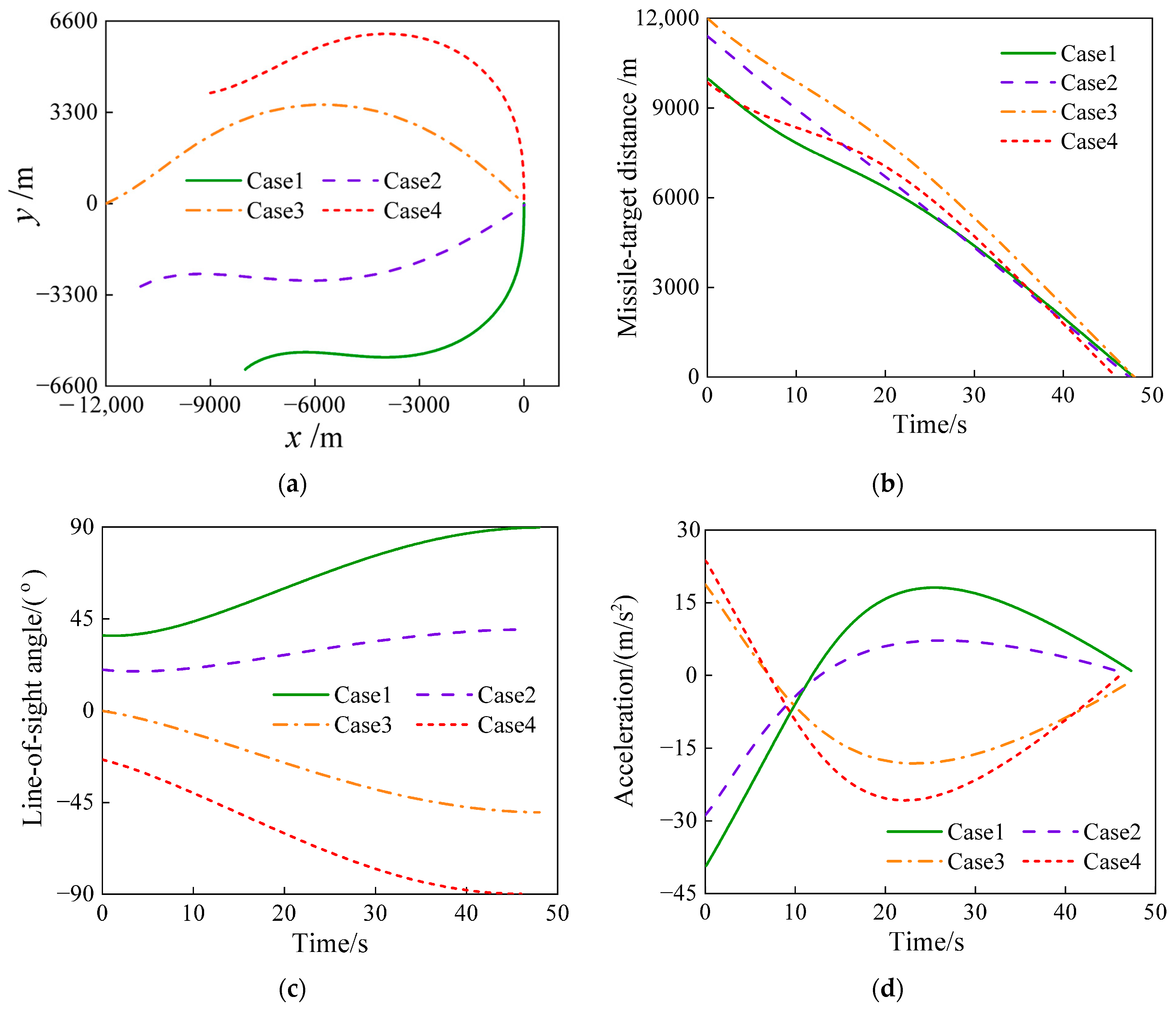
In this section, a variety of initial conditions (i.e., four cases) are used to verify the proposed impact angle control guidance law. The value of k 2 is chosen as k 2 = 0.12, and the other simulation parameters are listed in Table 1. The simulation results are shown in Figure 3.
We can observe in Figure 3a,b that the flight vehicle flies to the target along different trajectories and that the distance between the flight vehicle and the target finally converges to zero. In Figure 3c, all the desired impact angles can be achieved for different initial conditions. The acceleration, as shown in Figure 3d, changes continuously and can gradually converge to zero.

5.1.3. Considering the Velocity Variation

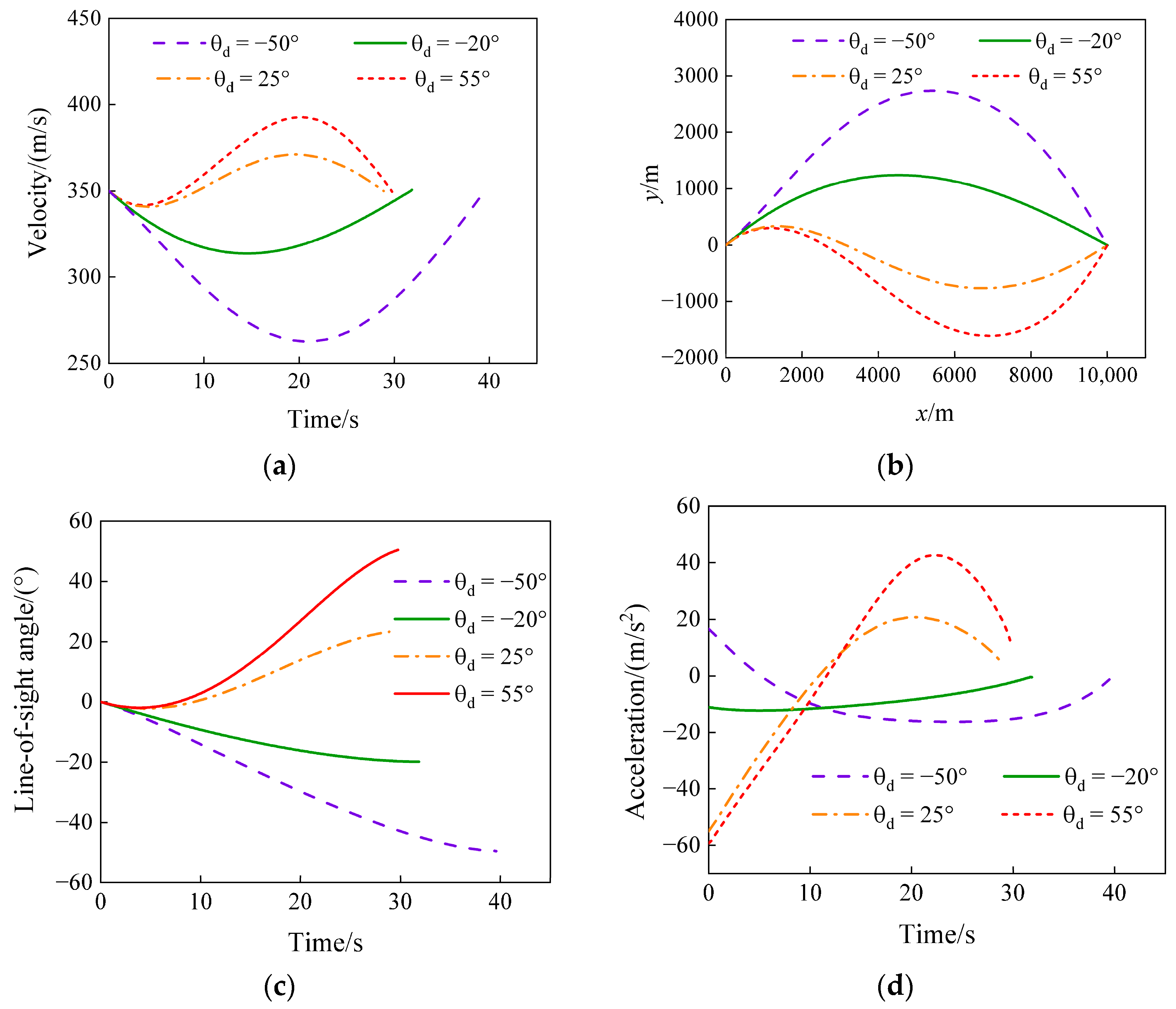
To further verify the effectiveness of the designed impact angle control guidance law, the variation in flight vehicle velocity is considered here. It is assumed that, in Equation (2), the thrust and drag of the flight vehicle counteract, and only the influence of gravity on the flight vehicle is considered. The initial velocity of the vehicle is set to 350 m/s, and the parameter k 2 in Equation (26) is set to 0.12. The initial heading error is 30°, and the simulation is carried out for four cases with desired impact angles of −50°, −20°, 25°, and 55°. The simulation results are shown in Figure 4.
Figure 4a shows the speed variation with time. When the expected impact angle is positive, the speed is generally greater than the initial speed; otherwise, it is generally smaller than the initial speed. A trend of decreasing first and then increasing is also shown. We can observe in Figure 4b that the flight vehicle can hit the target along different trajectories. In Figure 4c, the line-of-sight angle converges to the corresponding expected impact angle with time, demonstrating that the proposed guidance law can also meet the requirements of the impact angle when the speed varies with time. It is shown in Figure 4d that, when the expected impact angle is positive, the acceleration is greater at the beginning (because the difference between the actual and the ideal heading error is fairly large) and decreases as the difference between the actual and ideal heading errors decreases.

5.2. Simulation Results of Impact Time and Angle Control

The simulation conditions for the validation of ITACG are set as follows: The target is in a stationary state, the flight vehicle speed is equal to 250 m/s, the initial coordinate of the flight vehicle is (0, 0) m, the target coordinate is (10,000, 0) m, and the parameter σ in Equation (41) is set to σ = 0.001 .

5.2.1. Building a Specific Mapping Network

To perform the simulation, it is necessary to train the ideal flight path angle mapping network required in the impact time control phase. When the training dataset is constructed using the impact angle control guidance law in Section 3, Equations (1)–(5) are used, and the flight vehicle speed is set as a constant. When the flight vehicle speed changes, the training dataset should be replaced accordingly.
The way to establish the mapping network of the ideal flight path angle is as follows:
(a)
The values of the flight state variables are chosen as R [ 0 , 10000 ] m , θ [ 180 , 180 ] , γ [ 180 , 180 ] , and θ d { 30 , 60 , 90 } . For each expected impact angle in the θ d set, taking values with the respective range of flight states ( R , θ , γ ) results in a total of 155,160 sets of initial simulation conditions.
(b)
By performing the simulation of impact angle control under each set of initial conditions, the datasets S 1 ( R , θ , t , θ d ) and S 2 ( γ ) containing 155,160 sets of data are obtained. These data can be used to train the neural network, after which, the mapping network of the ideal flight path angle N e t γ ( R , θ , t , θ d ) is established.
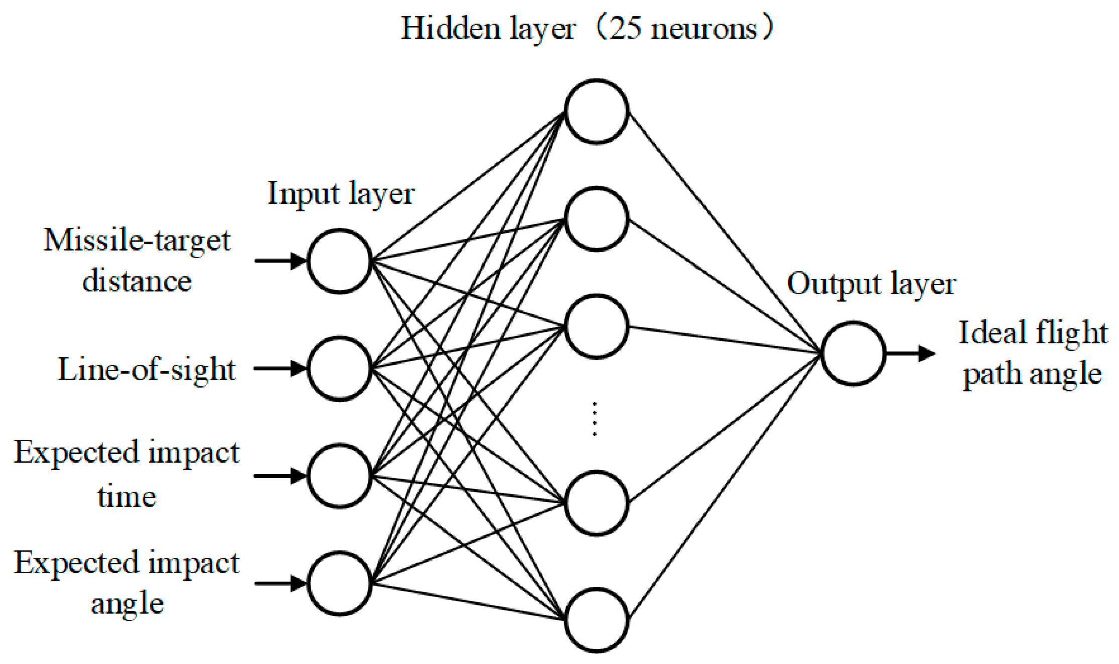
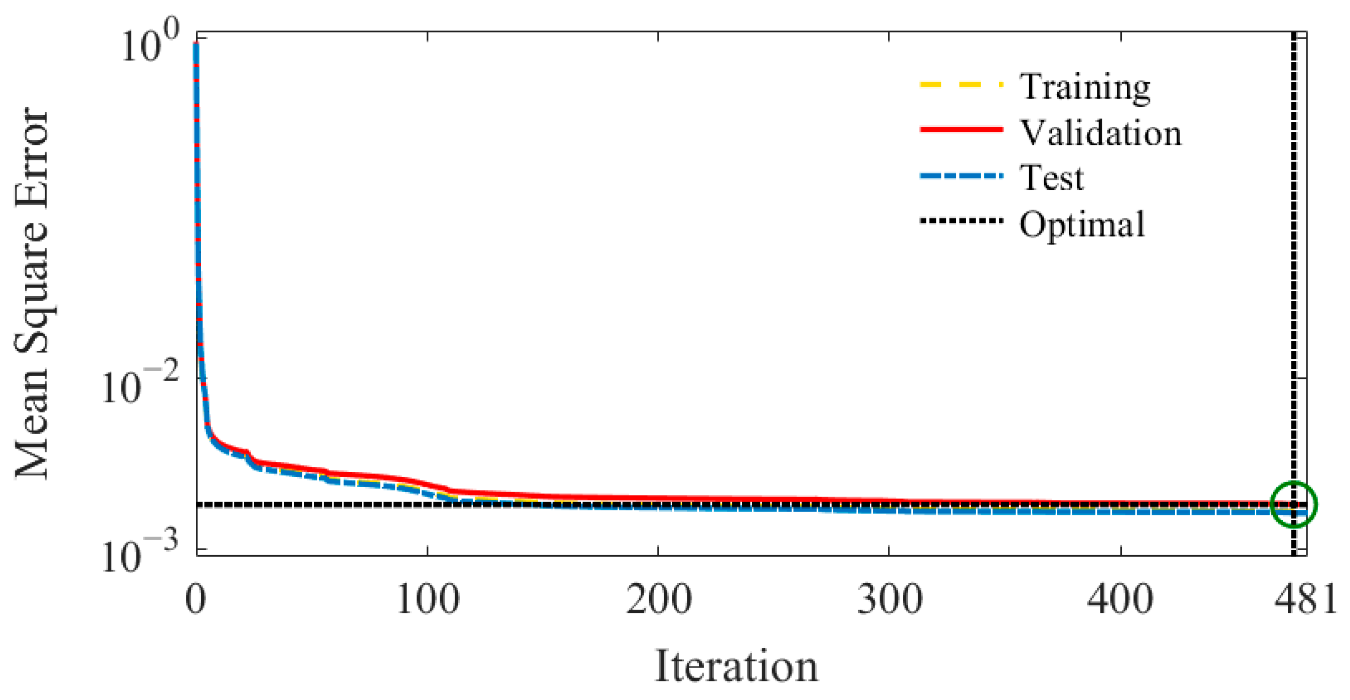
The fundamental structure of the neural network is shown in Figure 5. Based on the scale of the problem, the neural network selects a single hidden layer, four neuron nodes in the input layer, and one neuron node in the output layer. Since the number of hidden layer nodes significantly affects the approximation accuracy of the nonlinear function of the neural network, this study determines the number of hidden layer nodes by the step-by-step test method so that the network error converges to the accuracy threshold. It is determined by experiments that, when the hidden layer node is 25, the network error is small and the generalization ability is not affected. The objective function of the neural network training is the mean square error function, and the backpropagation algorithm is adopted. Prior to training, all the data in the dataset are normalized, of which 70% are used for training, 15% are used for verification, and 15% are used for testing. The maximum number of trainings is set to 1000. Figure 6 shows the variation in the mean square error during the training process.
Figure 6 shows the changes in the training error, verification error, and test error of network N e t γ ( R , θ , t , θ d ) with the number of iterations. The three kinds of errors obviously decrease with increasing iterations, and the training process ends at the 475th iteration with an error of 1.8 × 10 3 (the optimal mean square error when the training of the neural network ends), indicating that the training of the neural network is effective.

5.2.2. For Various Expected Impact Times with Constant Impact Angle

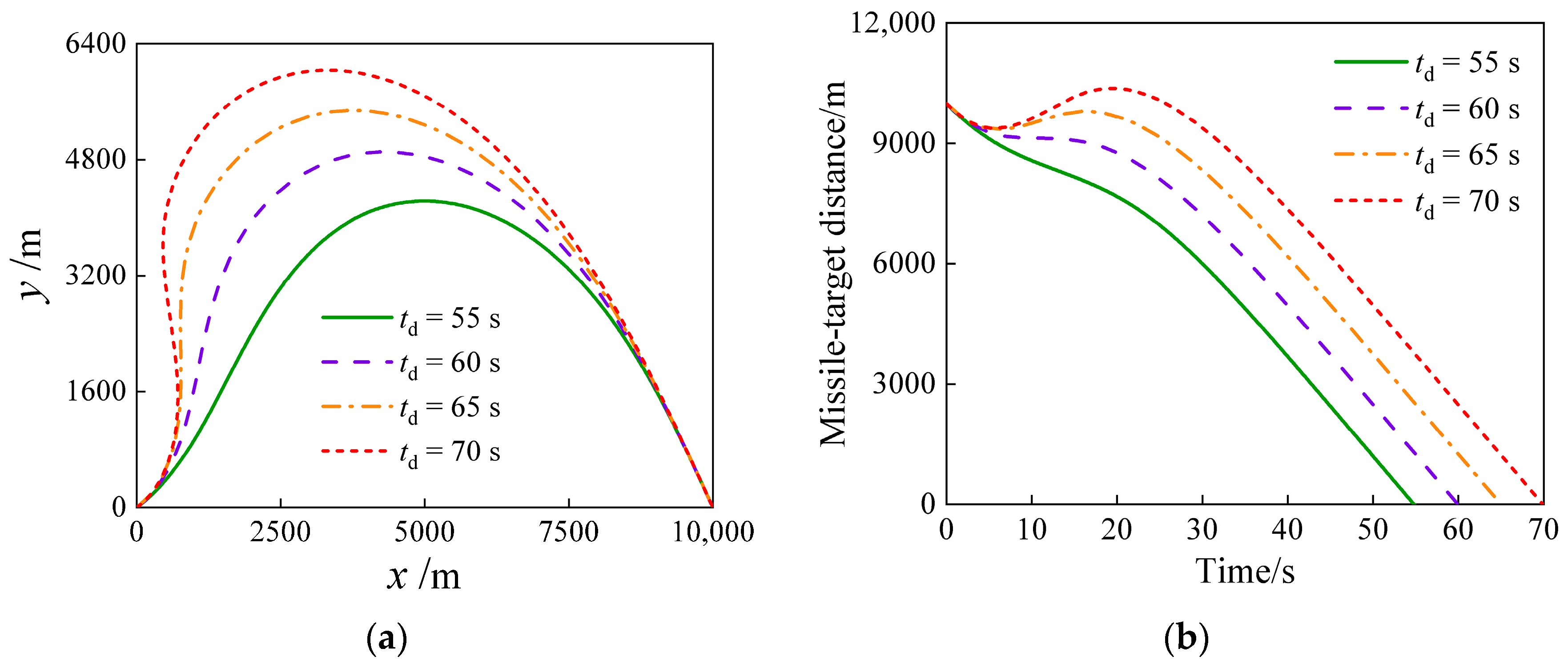
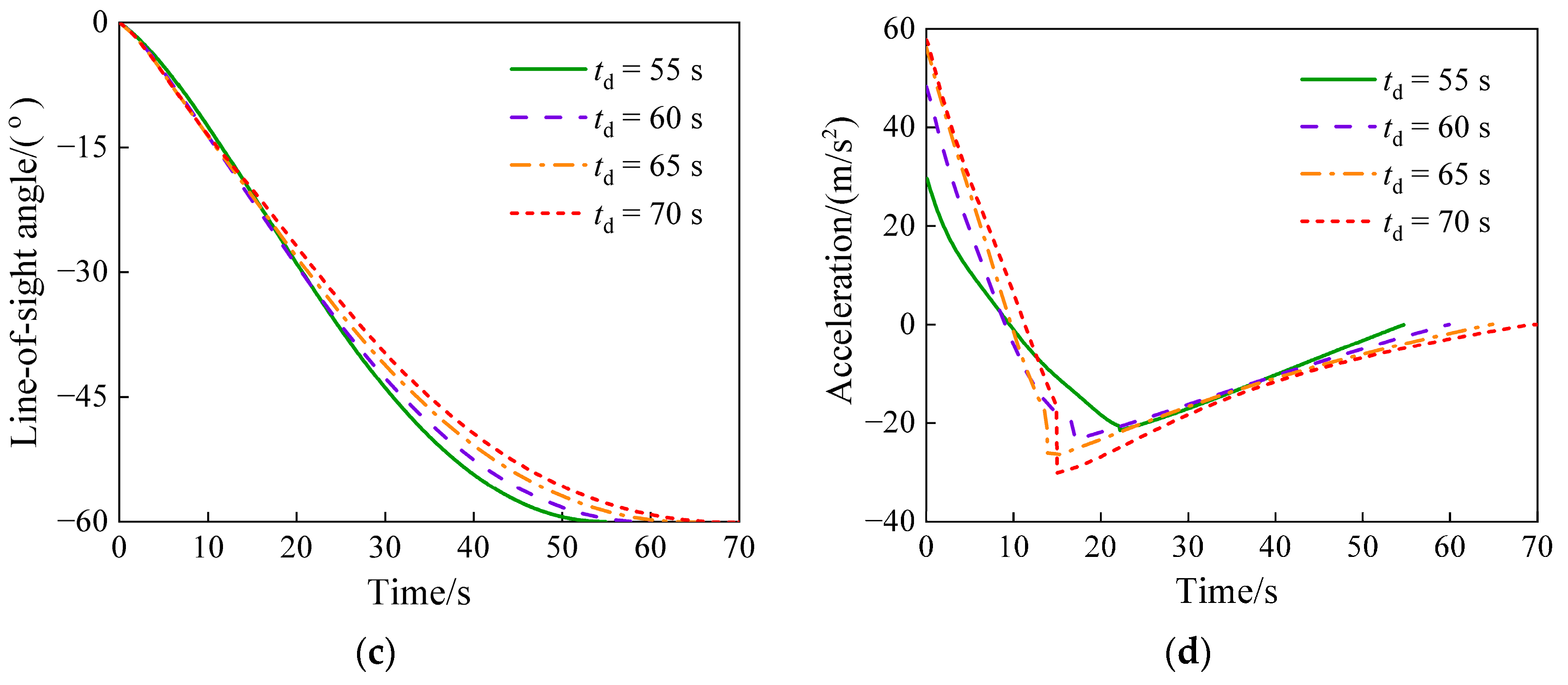
In this section, we assume that the expected impact angle is −60°and that the expected impact times are 55 s, 60 s, 65 s, and 70 s. The proposed impact time and angle control guidance law are verified under an initial heading error of 30°. The parameters in Equation (41) are chosen as k1 = 0.3 and k2 = 0.1. The simulation results are shown in Figure 7 and Table 2.
Figure 7a,b show the flight vehicle’s trajectory and the distance between the flight vehicle and target, respectively. The flight vehicle hits the target along different trajectories. However, the longer the impact time is, the more curved the trajectory is. To hit the target at the expected time and angle, a longer lag time needs to be achieved by slowing the change in the flight vehicle-target distance or by increasing the flight vehicle-target distance. Figure 7c shows the variation in the line-of-sight angle, in which the line-of-sight angle starts from zero and converges to the desired impact angle at the expected impact time. It is shown in Figure 7d that all the acceleration curves under the four conditions in the figure exhibit a small abrupt change at approximately t = 1 5   s , which is caused by the transformation from the impact time control stage to the impact angle control stage. In addition, these acceleration curves are relatively continuous at the remainder of the time, and all of them converge to zero at the last moment. We can observe from the time and angle control errors listed in Table 2 that not only does the proposed guidance law realize impact angle control but also controls the impact time very well.

5.2.3. Comparative Simulation

To further verify the proposed guidance law, the simulation results are compared with those in Ref. [28] under the same conditions. The initial heading error is assumed to be 60°, the expected impact angle is −60°, and the expected impact times are 55 s and 60 s. To compare with the results given by Ref. [28], a first-order inertia link with a time constant of 0.4 is added in the guidance process. For the parameters in Equation (41), the parameters are set as k1 = 0.3 and k2 = 0.1. Figure 8 shows the simulation results. Table 3 lists the total control energy J in the guidance process. The definition of J can be expressed as
J = 0 t f a m 2 / 2   d t
Figure 8a shows that the flight vehicle can hit the target at the same impact angle along different trajectories. The flight vehicle-target distance in Figure 8b converges to zero for each expected impact time. Figure 8c shows that the line-of-sight angle can converge to the desired impact angle for various expected impact times. Both guidance laws can realize impact time and impact angle control. We can observe in Figure 8d that the acceleration curve of the proposed guidance law changes smoothly in both cases, while the acceleration curve obtained by Ref. [28] oscillates violently in the first 10 s.
It can be observed in Table 3 that, under the two simulation conditions, the total control energy of the proposed guidance law is less than that in Ref. [28]. For t d = 55   s , the total control energy of the proposed guidance law is 7.67% lower than that of Ref. [28]. For t d = 60   s , the total control energy of this paper is 14.07% less than that of Ref. [28]. To a certain extent, this reflects the advantages of the proposed guidance law over the current research literature.

5.2.4. Simulation of Cooperative Attack

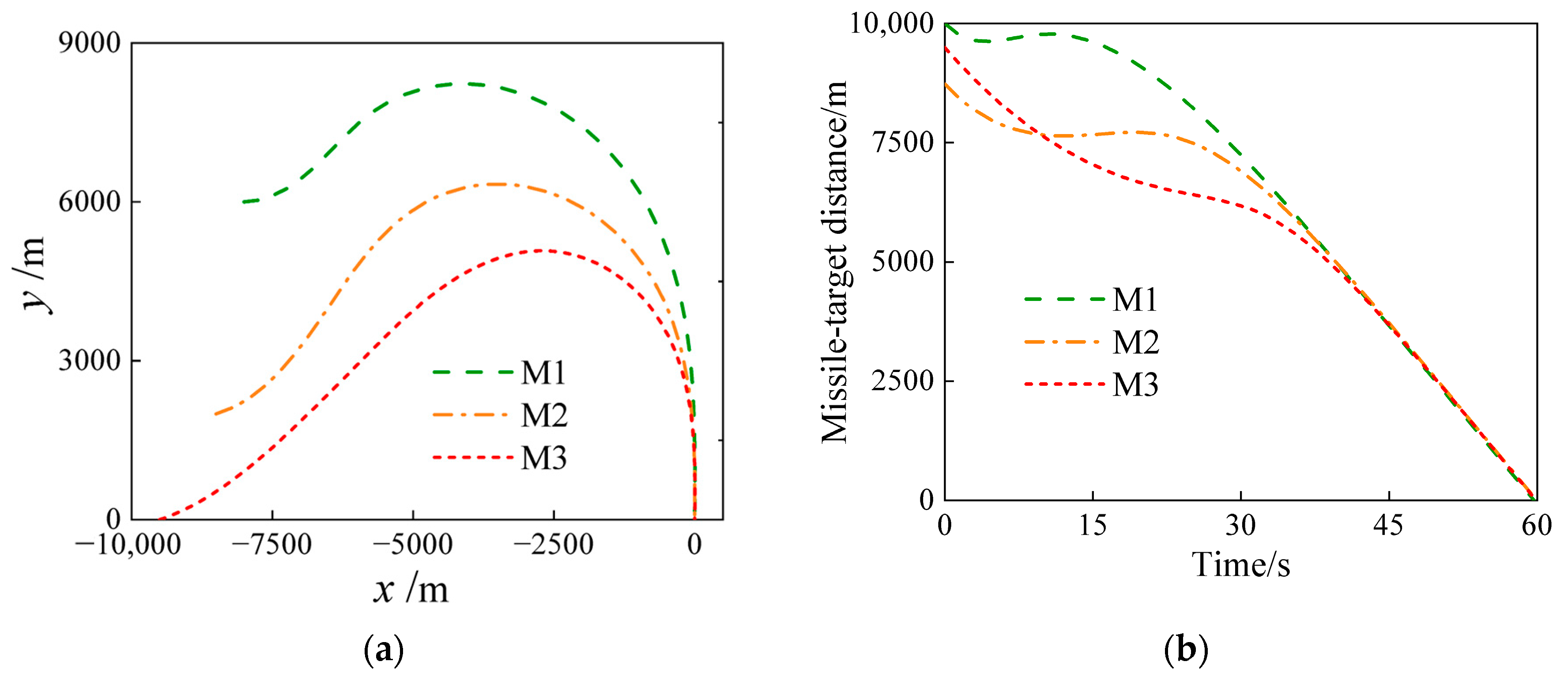
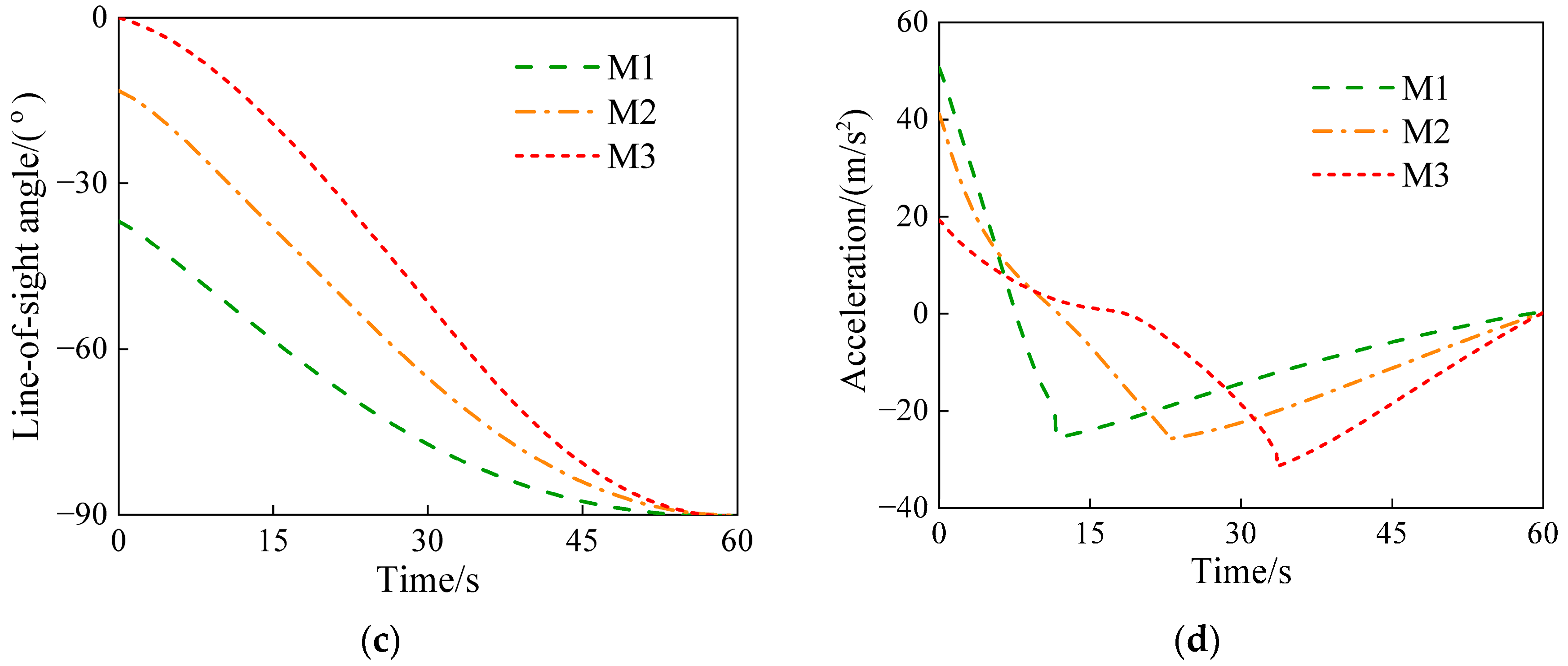
To further verify the effectiveness and feasibility of the proposed ITACG law, it is assumed that three flight vehicles (marked M1, M2, and M3) launch a cooperative attack against a stationary target. The expected impact time is set as t d = 60 s, and the desired impact angle is chosen to be θ d = 90 . For the parameters in the guidance command of Equation (41), we set k 1 = 0.4 and k 2 = 0.1 . The other simulation conditions are listed in Table 4, including initial positions and initial heading errors for multiple flight vehicles. Figure 9 shows the simulation results of the cooperative attack. The final errors of the impact time and impact angle are listed in Table 5.
We can observe in Table 5 that, for multiple flight vehicles with different flight vehicle-target distances and initial heading errors, the errors in the impact time and impact angle are relatively small, indicating that the proposed ITACG law can be effectively applied to the problem of cooperative attack. As shown in Figure 9a, three flight vehicles hit the target with the same impact angle (i.e., θ d = 90 ) along three different trajectories. Although the initial flight vehicle-target distances are different for these flight vehicles, all of them converge to zero within the expected time, realizing an effective cooperative attack, as shown in Figure 9b. Similarly, the line-of-sight angles demonstrated in Figure 9c for the three flight vehicles gradually arrive at the expected impact angle simultaneously, demonstrating the effectiveness of the impact angle control. Overall, the profiles of the accelerations for multiple flight vehicles, as shown in Figure 9d, are relatively continuous and smooth and converge to zero exactly at the desired time, which will increase the advantage of flight vehicle terminal attack and provide a sufficient margin for terminal control.

6. Conclusions

In this paper, the design of an effective impact time and angle control guidance law is presented by developing an application paradigm for the data-driven method. To address both the impact time and angle constraints, the guidance process is divided into two stages. Taking full advantage of PNG in practical engineering, a PNG-based IACG law is first designed for the second stage. A series of simulations of the proposed IACG law are performed with various initial flight state variables, and by using the ANN technique, the simulated data are used to construct a cost-effective mapping network surrogate model that can determine the ideal flight path angle at any time during flight. Consequently, an ITCG law for the first stage is proposed by using the ideal flight path angle. Finally, the PNG-based IACG law and the ANN-based ITCG law are used to form the novel ITACG law in two stages. In essence, when the error in the flight path angle in the first or second stage converges to zero, the desired impact time and angle can be achieved in the framework of PNG. Moreover, we theoretically prove the stability of the designed guidance law in the sense of Lyapunov. The simulation results show that the designed IACG law can work effectively under various conditions (e.g., it can adapt to cases with varying velocities). The proposed ITACG law not only performs well under various conditions (including cooperative attack) but is also independent of time-to-go and small-angle approximations (the error of impact time is less than 0.2 s, and the error of impact angle is less than 0.25°). Compared with the current research literature using the same simulation conditions, the proposed ITACG law has better acceleration performance and less control energy (for different impact time, the total control energy of the proposed guidance law is reduced by 7.67% and 14.07%, respectively, compared with other literature).
In any case, this study in this effort is just an attempt to apply a data-driven method to the design of the ITACG law. Thus, the application paradigm described in Section 4 is not the only one and is not necessarily optimal. There are also some limitations to the proposed ITACG law. For instance, this ITACG law is incapable of addressing cases with varying velocities (even though the IACG law in the second stage can address such cases). In future studies, more application paradigms of data-driven methods for the ITACG problem should be explored, and the follow-up work should focus on the adaptability of ITACG to more real flight conditions.

Supplementary Materials

The following supporting information can be downloaded at: https://www.mdpi.com/article/10.3390/aerospace11070540/s1.

Author Contributions

Conceptualization, S.C.; methodology, S.C. and J.H.; software, W.C. and J.H.; validation, W.C. and J.H.; formal analysis, W.C. and J.H.; investigation, J.H.; resources, J.H.; data curation, W.C.; writing—original draft preparation, W.C. and J.H.; writing—review and editing, S.C.; visualization, W.C. and J.H.; supervision, S.C.; project administration, S.C.; funding acquisition, S.C. All authors have read and agreed to the published version of the manuscript.

Funding

This research was funded by the Basic Research Program of Commission of Science and Technology, grant number [2023-JCJQ-JJ-0180].

Data Availability Statement

The original contributions presented in this study are included in the article/Supplementary Materials; further inquiries can be directed to the corresponding author/s.

Conflicts of Interest

Author Jia Huang was employed by the company Nanjing LES Information Technology Co., Ltd. The remaining authors declare that the research was conducted in the absence of any commercial or financial relationships that could be construed as a potential conflict of interest.

References

  1. Kim, M.; Grider, K.V. Terminal Guidance for Impact Attitude Angle Constrained Flight Trajectories. IEEE Trans. Aerosp. Electron. Syst. 1973, AES-9, 852–859. [Google Scholar]
  2. Ryoo, C.; Cho, H.; Tahk, M. Optimal Guidance Laws with Terminal Impact Angle Constraint. J. Guid. Control Dyn. 2005, 28, 724–732. [Google Scholar] [CrossRef]
  3. Jeon, I.; Lee, J.; Tahk, M. Impact-Time-Control Guidance Law for Anti-Ship Flight Vehicles. IEEE Trans. Control Syst. Technol. 2006, 14, 260–266. [Google Scholar] [CrossRef]
  4. Lee, J.; Jeon, I.; Tahk, M. Guidance Law to Control Impact Time and Angle. IEEE Trans. Aerosp. Electron. Syst. 2007, 43, 301–310. [Google Scholar]
  5. Lee, C.; Seo, M. New Insights into Guidance Laws with Terminal Angle Constraints. J. Guid. Control Dyn. 2018, 41, 1828–1833. [Google Scholar] [CrossRef]
  6. Li, H.; Wang, J.; He, S.; Lee, C. Nonlinear Optimal Impact-Angle-Constrained Guidance with Large Initial Heading Error. J. Guid. Control Dyn. 2021, 44, 1663–1676. [Google Scholar] [CrossRef]
  7. Lin, L.; Xin, M. Impact Angle Guidance Using State-Dependent (Differential) Riccati Equation: Unified Applicability Analysis. J. Guid. Control Dyn. 2020, 43, 2175–2182. [Google Scholar] [CrossRef]
  8. Li, B.; Tang, P.; Xu, H.; Zheng, D. Terminal Impact Angle Control Guidance Law Considering Target Observability. Aerospace 2022, 9, 193. [Google Scholar] [CrossRef]
  9. Wang, J.; Tao, X.; Dong, W.; Wang, C. Three-Dimensional Predefined-Time Impact Angle Control Guidance Law with Field-of-View Limit. J. Frankl. Inst. 2023, 360, 7621–7644. [Google Scholar] [CrossRef]
  10. Cho, D.; Kim, H.J.; Tahk, M. Nonsingular Sliding Mode Guidance for Impact Time Control. J. Guid. Control Dyn. 2016, 39, 61–68. [Google Scholar] [CrossRef]
  11. Chen, X.; Wang, J. Nonsingular Sliding-Mode Control for Field-of-View Constrained Impact Time Guidance. J. Guid. Control Dyn. 2018, 41, 1210–1218. [Google Scholar] [CrossRef]
  12. Hu, Q.; Han, T.; Xin, M. Sliding-Mode Impact Time Guidance Law Design for Various Target Motions. J. Guid. Control Dyn. 2019, 42, 136–148. [Google Scholar] [CrossRef]
  13. Tekin, R.; Erer, K.; Holzapfel, F. Quartic Range Shaping for Impact Time Control. In Proceedings of the 25th Mediterranean Conference on Control and Automation (MED), Valletta, Malta, 3–6 July 2017; pp. 1213–1218. [Google Scholar]
  14. Tekin, R.; Erer, K.; Holzapfel, F. Impact Time Control with Generalized-Polynomial Range Formulation. J. Guid. Control Dyn. 2018, 41, 1188–1193. [Google Scholar] [CrossRef]
  15. Tekin, R.; Erer, K.; Holzapfel, F. Polynomial Shaping of the Look Angle for Impact Time Control. J. Guid. Control Dyn. 2017, 40, 2666–2671. [Google Scholar] [CrossRef]
  16. Tekin, R.; Erer, K.; Holzapfel, F. Adaptive Impact Time Control via Look-Angle Shaping Under Varying Velocity. J. Guid. Control Dyn. 2017, 40, 3247–3255. [Google Scholar] [CrossRef]
  17. Tsalik, R.; Shima, T. Circular Impact-Time Guidance. J. Guid. Control Dyn. 2019, 42, 1836–1847. [Google Scholar] [CrossRef]
  18. Tekin, R.; Erer, K.; Holzapfel, F. Control of Impact Time with Increased Robustness via Feedback Linearization. J. Guid. Control Dyn. 2016, 39, 1678–1685. [Google Scholar] [CrossRef]
  19. Ma, S.; Wang, Z.; Wang, X.; Chen, Q. Three-Dimensional Impact Time Control Guidance Considering Field-of-View Constraint and Velocity Variation. Aerospace 2022, 9, 202. [Google Scholar] [CrossRef]
  20. Chang, S.; Chen, S. Nonsingular PNG-Based Impact Time Control Guidance with Lower Dependence on Time to go Estimate. Int. J. Aerosp. Eng. 2019, 2019, 5031245. [Google Scholar] [CrossRef]
  21. Wang, P.; Guo, Y.; Ma, G.; Wie, B. New Differential Geometric Guidance Strategies for Impact-Time Control Problem. J. Guid. Control Dyn. 2019, 42, 1982–1992. [Google Scholar] [CrossRef]
  22. Zhang, Y.; Ma, G.; Liu, A. Guidance Law with Impact Time and Impact Angle Constraints. Chin. J. Aeronaut. 2013, 26, 960–966. [Google Scholar] [CrossRef]
  23. Zhang, Y.; Wang, X.; Ma, G. Impact time control guidance law with large impact angle constraint. Proc. Inst. Mech. Eng. Part G J. Aerosp. Eng. 2015, 229, 2119–2131. [Google Scholar] [CrossRef]
  24. Harl, N.; Balakrishnan, S.N. Impact Time and Angle Guidance with Sliding Mode Control. IEEE Trans. Control Syst. Technol. 2012, 20, 1436–1449. [Google Scholar] [CrossRef]
  25. Kumar, S.R.; Ghose, D. Impact Time and Angle Control Guidance. In Proceedings of the AIAA Guidance, Navigation, and Control Conference, AIAA Paper 2015-0616, Kissimmee, FL, USA, 5–9 January 2015. [Google Scholar]
  26. Zhao, Y.; Sheng, Y.; Liu, X. Analytical Impact Time and Angle Guidance via Time-Varying Sliding Mode Technique. ISA Trans. 2016, 62, 164–176. [Google Scholar] [CrossRef] [PubMed]
  27. Hou, Z.; Yang, Y.; Liu, L.; Wang, Y. Terminal Sliding Mode Control Based Impact Time and Angle Constrained Guidance. Aerosp. Sci. Technol. 2019, 93, 105142. [Google Scholar] [CrossRef]
  28. Chen, X.; Wang, J. Sliding-Mode Guidance for Simultaneous Control of Impact Time and Angle. J. Guid. Control Dyn. 2019, 42, 394–401. [Google Scholar] [CrossRef]
  29. Liu, X.; Li, G. Adaptive Sliding Mode Guidance with Impact Time and Angle Constraints. IEEE Access 2020, 8, 26926–26932. [Google Scholar] [CrossRef]
  30. Chen, Z.; Chen, W.; Liu, X.; Cheng, J. Three-Dimensional Fixed-Time Robust Cooperative Guidance Law for Simultaneous Attack with Impact Angle Constraint. Aerosp. Sci. Technol. 2021, 110, 106523. [Google Scholar] [CrossRef]
  31. Yu, H.; Dai, K.; Li, H.; Zou, Y.; Ma, X.; Ma, S.; Zhang, H. Three-Dimensional Adaptive Fixed-Time Cooperative Guidance Law with Impact Time and Angle Constraints. Aerosp. Sci. Technol. 2022, 123, 107450. [Google Scholar] [CrossRef]
  32. You, H.; Chang, X.; Zhao, J.; Wang, S.; Zhang, Y. Three-Dimensional Impact-Angle-Constrained Fixed-Time Cooperative Guidance Algorithm with Adjustable Impact Time. Aerosp. Sci. Technol. 2023, 141, 108574. [Google Scholar] [CrossRef]
  33. Kim, T.; Lee, C.; Jeon, I. Augmented Polynomial Guidance with Impact Time and Angle Constraints. IEEE Trans. Aerosp. Electron. Syst. 2013, 49, 2806–2817. [Google Scholar] [CrossRef]
  34. Zhao, Y.; Sheng, Y.; Liu, X. Trajectory Reshaping Based Guidance with Impact Time and Angle Constraints. Chin. J. Aeronaut. 2016, 29, 984–994. [Google Scholar] [CrossRef]
  35. Kang, S.; Tekin, R.; Holzapfel, F. Generalized Impact Time and Angle Control via Look-Angle Shaping. J. Guid. Control Dyn. 2019, 42, 695–702. [Google Scholar] [CrossRef]
  36. Tekin, R.; Erer, K. Impact Time and Angle Control Against Moving Targets with Look Angle Shaping. J. Guid. Control Dyn. 2020, 43, 1020–1025. [Google Scholar] [CrossRef]
  37. Wang, P.; Guo, Y.; Ma, G.; Lee, C.; Wie, B. New Look-Angle Tracking Guidance Strategy for Impact Time and Angle Control. J. Guid. Control Dyn. 2022, 45, 545–557. [Google Scholar] [CrossRef]
  38. Catak, A.; Emre, K. Dynamic Line of Sight Shaping for Impact Time and Angle Control Guidance. IFAC Pap. Line 2023, 56, 4514–4519. [Google Scholar] [CrossRef]
  39. Erer, K.S.; Tekin, R. Impact Time and Angle Control Based on Constrained Optimal Solutions. J. Guid. Control Dyn. 2016, 39, 2445–2451. [Google Scholar] [CrossRef]
  40. Lee, J.; Kim, H.J. Impact Time and Angle Control Guidance with Rendezvous Concept. In Proceedings of the AIAA Guidance, Navigation, and Control Conference, AIAA Paper 2018-1322, Kissimmee, FL, USA, 8–12 January 2018. [Google Scholar]
  41. Chen, X.; Wang, J. Optimal Control Based Guidance Law to Control Both Impact Time and Impact Angle. Aerosp. Sci. Technol. 2019, 84, 454–463. [Google Scholar] [CrossRef]
  42. Zhang, W.; Chen, W.; Li, J.; Yu, W. Guidance Algorithm for Impact Time, Angle, and Acceleration Control Under Varying Velocity Condition. Aerosp. Sci. Technol. 2022, 123, 107462. [Google Scholar] [CrossRef]
  43. Chen, Y.; Wu, S.; Wang, X. Impact Time and Angle Control Optimal Guidance with Field-of-View Constraint. J. Guid. Control Dyn. 2022, 45, 2369–2378. [Google Scholar] [CrossRef]
  44. Hu, Q.; Han, T.; Xin, M. New Impact Time and Angle Guidance Strategy via Virtual Target Approach. J. Guid. Control Dyn. 2018, 41, 1755–1765. [Google Scholar] [CrossRef]
  45. Wang, C.; Yu, H.; Dong, W.; Wang, J. Three-Dimensional Impact Angle and Time Control Guidance Law Based on Two-Stage Strategy. IEEE Trans. Aerosp. Electron. Syst. 2022, 58, 5361–5372. [Google Scholar] [CrossRef]
  46. Zhang, Z.; Ma, K.; Zhang, G.; Yan, L. Virtual Target Approach-Based Optimal Guidance Law with Both Impact Time and Terminal Angle Constraints. Nonlinear Dyn. 2022, 107, 3521–3541. [Google Scholar] [CrossRef]
  47. Zhu, J.; Su, D.; Xie, Y.; Sun, H. Impact Time and Angle Control Guidance Independent of Time-to-go Prediction. Aerosp. Sci. Technol. 2019, 86, 818–825. [Google Scholar] [CrossRef]
  48. Chen, X.; Wang, J. Two-stage Guidance Law with Impact Time and Angle Constraints. Nonlinear Dyn. 2019, 95, 2575–2590. [Google Scholar] [CrossRef]
  49. Kim, H.; Lee, J.; Kim, H.J.; Kwon, H.; Park, J. Look-Angle-Shaping Guidance Law for Impact Angle and Time Control with Field-of-View Constraint. IEEE Trans. Aerosp. Electron. Syst. 2020, 56, 1602–1612. [Google Scholar] [CrossRef]
  50. Yan, X.; Zhu, J.; Kuang, M.; Yuan, X. A Computational-Geometry-Based 3-Dimensional Guidance Law to Control Impact Time and Angle. Aerosp. Sci. Technol. 2020, 98, 105672. [Google Scholar] [CrossRef]
  51. Hou, L.; Luo, H.; He, S.; Shi, H.; Shin, H. An Optimal Geometrical Guidance Law for Impact Time and Angle Control. IEEE Trans. Aerosp. Electron. Syst. 2023, 59, 9821–9830. [Google Scholar] [CrossRef]
  52. Wang, Z.; Hu, Q.; Han, T.; Xin, M. Two-Stage Guidance Law with Constrained Impact via Circle Involute. IEEE Trans. Aerosp. Electron. Syst. 2021, 57, 1301–1316. [Google Scholar] [CrossRef]
  53. Shima, T.; Livermore, R. Deviated Pure-Pursuit-Based Optimal Guidance Law for Imposing Intercept Time and Angle. J. Guid. Control Dyn. 2018, 41, 1805–1812. [Google Scholar]
  54. Manchester, I.R.; Savkin, A.V.; Faruqi, F.A. Method for Optical-Flow-Based Precision Missile Guidance. IEEE Trans. Aerosp. Electron. Syst. 2008, 44, 836–842. [Google Scholar] [CrossRef]
  55. Dong, W.; Wang, C.; Liu, J.; Wang, J.; Xin, M. Three-Dimensional Vector Guidance Law with Impact Time and Angle Constraints. J. Frankl. Inst. 2023, 360, 693–718. [Google Scholar] [CrossRef]
  56. Chen, Y.; Wang, J.; Shan, J. Cooperative guidance for multiple powered Flight Vehicles with constrained impact and bounded speed. J. Guid. Control Dyn. 2021, 44, 825–840. [Google Scholar] [CrossRef]
  57. Brunton, S.L.; Kutz, J.N.; Manohar, K.; Aravkin, A.Y.; Morgansen, K. Data-Driven Aerospace Engineering: Reframing the Industry with Machine Learning. AIAA J. 2021, 59, 2820–2847. [Google Scholar] [CrossRef]
  58. Yan, L.; Chang, X.; Wang, N.; Zhang, L.; Liu, W.; Deng, X. Aerodynamic Identification and Control Law Design of a Flight Vehicle Using Machine Learning. AIAA J. 2023, 61, 2998–3018. [Google Scholar] [CrossRef]
  59. He, S.; Shin, H.S.; Tsourdos, A. Computational Flight Vehicle Guidance: A Deep Reinforcement Learning Approach. J. Aerosp. Inf. Syst. 2021, 18, 571–582. [Google Scholar]
  60. Cheng, L.; Jiang, F.; Wang, Z. Multiconstrained Real-Time Entry Guidance Using Deep Neural Networks. IEEE Trans. Aerosp. Electron. Syst. 2021, 57, 325–340. [Google Scholar] [CrossRef]
  61. Shen, Y.; Chen, M.; Skelton, R.E. A Markov data-based approach to system identification and output error covariance analysis for tensegrity structures. Nonlinear Dyn. 2024, 112, 7215–7231. [Google Scholar] [CrossRef]
  62. Shen, Y.; Chen, M.; Skelton, R.E. Q-Markov Covariance equivalent realizations for unstable and marginally stable systems. Mech. Syst. Signal Process. 2023, 196, 110343. [Google Scholar] [CrossRef]
  63. Li, Q.; Zhang, W.; Han, G.; Zhang, Y. Finite Time Convergent Wavelet Neural Network Sliding Mode Control Guidance Law with Impact Angle Constraint. Int. J. Autom. Comput. 2015, 12, 588–599. [Google Scholar] [CrossRef]
  64. Guo, Y.; Li, X.; Zhang, H.; Cai, M.; He, F. Data-Driven Method for Impact Time Control Based on Proportional Navigation Guidance. J. Guid. Control Dyn. 2020, 43, 955–966. [Google Scholar] [CrossRef]
  65. Huang, J.; Chang, S. Data-Driven Method Based Impact Time and Impact Angle Control Guidance Law. Syst. Eng. Electron. 2022, 44, 3213–3220. (In Chinese) [Google Scholar]
  66. Hagan, M.T.; Demuth, H.B.; Beale, M.H.; Jesús, O.D. Neural Network Design, 2nd ed.; eBook; PWS Publishing Co.: Pacific Grove, CA, USA, 2017. [Google Scholar]
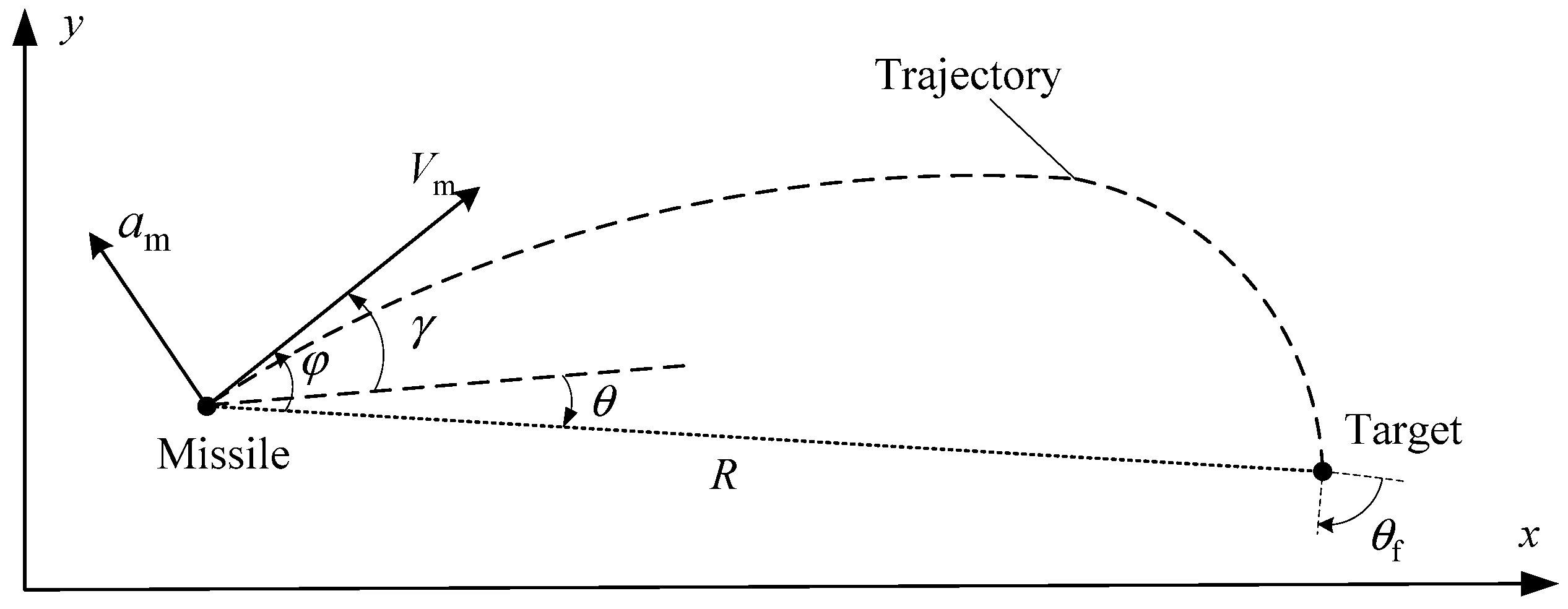
Figure 1. Engagement geometry for a stationary target.
Aerospace 11 00540 g001
Figure 2. Simulation results for different expected impact angles. (a) Trajectory, (b) Heading error, (c) Line-of-sight angle, (d) Acceleration.
Aerospace 11 00540 g002
Figure 3. Simulation results for different initial conditions. (a) Trajectory, (b) Flight vehicle-target distance, (c) Line-of-sight angle, (d) Acceleration.
Aerospace 11 00540 g003
Figure 4. Simulation results for various flight vehicle velocities. (a) Velocity, (b) Trajectory, (c) Line-of-sight angle, (d) Acceleration.
Aerospace 11 00540 g004
Figure 5. Artificial neural network structure diagram.
Aerospace 11 00540 g005
Figure 6. Variation in the mean square error.
Aerospace 11 00540 g006
Figure 7. Results for various expected impact times with an impact angle of −60°. (a) Velocity, (b) Trajectory, (c) Line-of-sight angle, (d) Acceleration.
Aerospace 11 00540 g007aAerospace 11 00540 g007b
Figure 8. Simulation results compared with those of Ref. [28]. Chen, X. (2019) represents the results under the same conditions in Ref. [28]. (a) Velocity, (b) Trajectory, (c) Line-of-sight angle, (d) Acceleration.
Aerospace 11 00540 g008
Figure 9. Simulation results of cooperative attack. (a) Velocity, (b) Trajectory, (c) Line-of-sight angle, (d) Acceleration.
Aerospace 11 00540 g009aAerospace 11 00540 g009b
Table 1. Simulation parameters under different initial conditions.
Case NoInitial Position (m)Flight Vehicle-Target Distance (m)Velocity (m/s2)Initial Heading
Error (°)
Desired Impact
Angle (°)
1(−8000, −6000)10,0002501090
2(−11,000, −3000)11,4022502040
3(−12,000, 0)12,00030030−50
4(−9000, 4000)984930040−90
Table 2. Time and angle errors for various impact time controls with an impact angle of −60°.
Case NoExpected Impact Time (s)Impact Time Error (s)Impact Angle Error (o)
1550.1770.014
2600.0170.021
3650.0500.037
4700.0300.083
Table 3. Total control energy for different impact times with an impact angle of −60°.
Case No.Guidance LawImpact Time (s) Total   Control   Energy   ( m 2 / s 3 )
1Proposed55 3.49 × 10 3
2Ref. [28]55 3.78 × 10 3
3Proposed60 4.46 × 10 3
4Ref. [28]60 5.19 × 10 3
Table 4. Simulation conditions for the cooperative attack.
ObjectInitial
Position (m)
Distance between
Flight Vehicle and Target (m)
Initial Heading
Error (°)
M1(−8000, 6000)10,00040
M2(−8500, 2000)873230
M3(−9500, 0)950020
Target(0, 0)N/A 1N/A 1
1 N/A, not applicable.
Table 5. Errors of the impact time and impact angle for the cooperative attack.
ObjectError of Impact Time (s)Error of Impact Angle (°)
M10.0320.13
M20.0150.04
M30.0330.21
Disclaimer/Publisher’s Note: The statements, opinions and data contained in all publications are solely those of the individual author(s) and contributor(s) and not of MDPI and/or the editor(s). MDPI and/or the editor(s) disclaim responsibility for any injury to people or property resulting from any ideas, methods, instructions or products referred to in the content.