Abstract
To meet the time-coordinated requirement of hypersonic gliding vehicles to reach a single target simultaneously in the presence of no-fly-zone constraints, this paper proposes a time-coordinated A* path planning method considering multiple constraints. The path planning method is designed based on an analytical steady gliding path model and the framework of the A* algorithm. Firstly, an analytical steady gliding path model is designed based on a quadratic function-type altitude-velocity profile. It can derive the control commands explicitly according to the desired terminal altitude and velocity, thus establishing a mapping between the terminal states and the control commands. Secondly, the node extension method of the A* algorithm is improved based on the mapping. Taking the terminal states as new design variables, a feasible path-node set is produced by a one-step integration using the control commands derived according to different terminal states. This node extension method ensures the feasibility of the path nodes while satisfying terminal constraints. Next, the path evaluation function of the A* algorithm is modified by introducing a heuristic switching term to select the most proper node as a waypoint, aiming to minimize the arrival time deviation. Meanwhile, introducing the penalty items into the path evaluation function satisfies the no-fly-zone constraints, process constraints, and control variable constraints. Finally, an online time-coordinated method is proposed to determine a commonly desired arrival time for several hypersonic gliding vehicles. It eliminates the need to specify the arrival time in advance and improves the capability to deal with sudden threats, increasing the path planning method’s online application capability. The proposed method can achieve online time-coordinated multi-constraint path planning for several hypersonic gliding vehicles, whose effectiveness and superiority are verified by simulations.
1. Introduction
A hypersonic gliding vehicle (HGV) is a type of long-range non-ballistic maneuver reentry vehicle that glides in near space unpowered and has the characteristics of high velocity, strong maneuverability, and wide coverage of reachable area [1]. It has been a hot research topic in the field of aircraft in recent years. With the maturity of the cooperative warfare system, multiple HGVs simultaneously reaching a single target has become a new requirement. Multi-flight time-coordination has received much attention because of its advantages of improving the defense penetration probability, increasing the surveillance range, and achieving saturation attacks to significantly enhance combat effectiveness. Meanwhile, it is equally vital for HGVs to avoid no-fly zones distributed on the battlefield to increase flight safety. Path planning is the core of the multi-vehicle mission planning system, the basis and prerequisite for mission execution [2]. The glide flight segment in the atmosphere accounts for more than 90% of the total flight time of HGVs, so it is necessary to research cooperative path planning methods for the gliding flight segment of HGVs in the presence of numerous no-fly zones.
The path-planning problem has always been the research hotspot for flight vehicles. The existing path-planning methods can be mainly divided into two categories [3] based on the considered model: path-planning considering kinematics and path-planning considering dynamics (or generally called trajectory planning). For ease of description, this article refers to these two types of methods as the kinematic path-planning method (KPM) and the dynamic path-planning method (DPM).
The KPM plans the path considering the vehicle’s kinematics model, dealing with the path planning problem as the selection problem of sequential waypoints. This type of method has a simple problem model and a strong ability to handle no-fly-zone constraints, making it highly efficient for planning. The KPM was initially used to solve the obstacle avoidance path-planning problem for a single vehicle. The commonly used single-vehicle KPM can be roughly divided into three categories: graph search method [4,5,6,7,8,9], numerical optimization method [10,11,12,13], and potential field method [14]. The graph search approach creates a state-space diagram of the path planning problem using the vehicle’s current state and transitions between states, then evaluates the path planning constraints to determine the optimal or suboptimal path from the state-space diagram. The A* algorithm [7,8,9] is a widely used graph search algorithm. The A* algorithm improves search efficiency by introducing heuristic information and can guarantee optimality and completeness under certain assumptions, so it has been studied and used widely. The numerical optimization method takes the shortest path as the objective function, constructs a constrained optimization model, and then solves the model using the genetic algorithm [10], particle swarm algorithm [11,12], ant colony algorithm [13], or other optimization algorithms. The potential field method establishes the potential function in the planning space by using the planning target point as the attraction field and the threats as the repulsion field. It determines the vehicle’s path according to the gradient of the potential function and its constraints [14]. Most of the studies on multi-vehicle cooperative path planning problems are based on those of a single vehicle, which generates the path for multiple vehicles to reach the target point simultaneously by considering spatiotemporal cooperation requirements among vehicles in the process of path node extension [15], optimization modeling [16], or potential function construction [17]. Most of the algorithms mentioned above take UAVs as the study object and tend to treat the flight velocity as a constant and ignore the dynamic model of UAVs to simplify the problem and improve path planning efficiency. Compared with UAVs, HGVs have the following characteristics: (1) They have no thrust, which means the control ability of velocity is weak, so the constant velocity assumption is unsuitable. (2) They pass through the atmosphere with a high velocity, which requires satisfying strict force-thermal constraints. (3) They have strong nonlinear dynamics, which cannot simply ignore the dynamical model. Therefore, the methods mentioned above cannot be directly used to solve the path planning problem of HGVs.
The DPM constructs a path-planning model that considers the vehicle’s dynamic models and deals with the path-planning problem as a control sequence-solving problem. Due to the consideration of the vehicle’s dynamics model, the DPM can satisfy more force-thermal constraints, making it more feasible for HGV. The trajectory optimization method is a widely studied DPM. It can obtain a high-precision path that satisfies multiple constraints and optimizes the performance index. In Refs. [18,19,20,21], the hp-adaptive Gaussian pseudo-spectral method (hp-AGPM), particle swarm-Gaussian pseudo-spectral method (PS-GPM), and sequential convex optimization algorithm are used to realize the trajectory optimization of HGVs with the arrival time as the performance index, respectively. Although there is no simulation validation of multi-vehicle cooperation in these papers, these methods have the potential to be applied for cooperative path planning by setting the same arrival time for multiple vehicles. In Refs. [22,23], the convex optimization algorithm is used to achieve cooperative path planning by adding the arrival time as a constraint. However, the expected arrival time of each vehicle needs to be continuously optimized during the flight, which leads to a significant computational effort for the algorithm. Although the trajectory optimization method has high accuracy and strong constraint processing ability, it requires a large amount of computation. To improve the online application ability, another type of DPM called trajectory planning has been extensively researched in recent years. The trajectory-planning method generally divides the path-planning problem into longitudinal and lateral profiles. The longitudinal profile parameters are iteratively designed to ensure flight performance. In the lateral profiles, the bank-angle reversal strategy is used to control the ground path. Compared to the trajectory optimization method, the trajectory planning method can achieve rapid path planning because it simplifies the problem. In Ref. [24], a combination of the drag-acceleration profile and predictor-corrector method was used to study the multiple HGVs’ time-coordinated reentry guidance problem. However, the reference drag acceleration profile needs to be updated at each guidance cycle, which is computationally intensive and increases the algorithm’s complexity. Ref. [25] analyzed the relationships among time-to-go, range-to-go, and terminal velocity, based on which the terminal velocity was selected as a control variable to achieve arrival time constraints. Ref. [26] took the longitudinal lift-drag ratio as a design variable, and time-constrained path planning was achieved, effectively improving the controllable time range. Ref. [27] designed a double-corridor strategy to achieve lateral guidance with terminal time constraints. In addition, the references [22,23,24,25,26,27] need to determine the arrival time range of each vehicle by numerical optimization before path planning and then integrate the arrival time ranges of all vehicles to select an appropriate predesignated arrival time, which is a significant workload before planning and is not suitable for online path planning of large-scale vehicle clusters. In Ref. [28], a two-stage method was proposed to achieve rapid path planning considering time and heading angle constraints, and the arrival time is determined online by communication between HGVs. In addition, the rapid path planning methods shown in refs. [22,23,24,25,26,27,28] did not consider the constraints of no-fly zones.
In summary, the KPM has high computational efficiency and a solid ability to handle no-fly-zone constraints. However, the feasibility of the flight path cannot be guaranteed. The DPM, which can be divided into trajectory optimization and trajectory planning, can satisfy the dynamic constraints of HGVs. However, trajectory optimization requires a large amount of computation. Trajectory planning rarely considers the no-fly-zone constraints. Moreover, most of the DPM needs to specify arrival times for every HGV in advance, which limits the online application abilities of the methods. Currently, there is relatively little research on HGV online path planning that considers both time-coordinated requirements and no-fly-zone constraints.
In response to the above issues, this paper combines KPM and DPM to propose a time-coordinated A* path planning method. An analytical steady gliding path model is first designed to obtain a feasible path that satisfies terminal constraints. On this basis, an HGV time-coordinated path planning method is designed based on the frame of the A* algorithm, which is a classic KPM. The proposed time-coordinated path planning method combines the advantages of KPM and DPM. On the one hand, this method inherits the efficiency and no-fly-zone avoidance ability of the A* algorithm. So, it can plan paths satisfying no-fly-zone constraints rapidly. On the other hand, the analytical steady gliding path model is introduced in the node extension process of the A* algorithm. Thus, the feasibility of the planned path can be guaranteed. The time-coordinated requirement is satisfied by analytical time estimation and introducing the time control term into the A* algorithm’s evaluation function. Moreover, the arrival time of the HGVs is specified according to an online arrival time coordination method. Thus, the time-coordinated path planning method does not need to specify the arrival time of each vehicle in advance and has a large potential for online application. The main contributions of this paper can be summarized as follows:
- (1)
- An analytical steady gliding path model is established. The analytical steady gliding path is designed based on a quadratic function altitude-velocity profile. The control commands are derived explicitly according to the desired terminal altitude and velocity instead of through trajectory iteration, which improves the planning efficiency. The analytical steady gliding path model constructs the mapping between the control variables and the terminal states, which provides an important basis for improving the A* algorithm to satisfy the dynamic and terminal constraints.
- (2)
- An improved A* algorithm that can achieve arrival time control is proposed for HGV. On the one hand, to solve the problem of the infeasible path for HGV in the classic A* algorithm, a dynamically considered path extension method is proposed based on the analytical steady gliding path mode. The path extension method takes terminal altitude and velocity as the design variables and uses the established analytical steady gliding path model for one-step integration to obtain path nodes. This path extension method ensures path nodes satisfy the dynamic constraints, making it possible for the A* algorithm to be applied to the path planning problem of HGV. On the other hand, the evaluation function of the A* algorithm is modified to consider the arrival time constraint. A heuristic switching function is designed and introduced in the path evaluation function to achieve arrival time control. The penalty function is introduced to ensure that the vehicles’ paths satisfy the no-fly zone and force-thermal constraints. Thus, the improved A* algorithm can simultaneously consider time-coordination requirements and no-fly-zone constraints.
- (3)
- An online arrival time coordination method is proposed. The method determines the expected arrival time of all HGVs based on each vehicle’s time-to-go prediction results, eliminating the need to specify arrival times in advance. The arrival time is adjusted with the change in the HGVs’ states. Thus, the path-planning method can respond to sudden threats, increasing the online application ability.
This article is organized as follows: Section 2 formulates the problem researched in this paper. Section 3 proposes an analytical steady gliding path model that can derive the control commands explicitly according to the desired terminal altitude and velocity. Section 4 proposes a time-coordinated A* path planning method by combining the proposed analytical steady gliding path model and the framework of the classic A* algorithm. This path-planning method can derive feasible paths for several HGVs satisfying time-coordinated requirements and no-fly-zone constraints. Simulation results are provided in Section 5. Section 6 concludes this paper.
2. Problem Formulation
2.1. Dynamic Model
The definitions of the HGV states are shown in Figure 1, and the dynamic functions of an HGV can be described as [20]:
where is the radial distance from the Earth center to the vehicle, which satisfies the relation with the vehicle altitude and the radius of the Earth , so the following often describes the flight altitude by the radial distance . is the longitude, is the latitude, is the velocity, is the flight-path angle, is the velocity heading angle, is the bank angle, and is the gravitational acceleration.
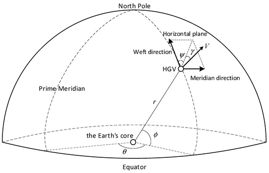
Figure 1.
Definition of the states.
and are the accelerations of lift and drag, respectively, satisfying
where and are the lift and drag coefficients, respectively, and they are functions related to Mach number and angle of attack (AOA) . is the dynamic pressure, is the reference area, is the mass of the vehicle.
2.2. Problem Statement
The 3-D path planning problem of multiple HGVs striking the same target simultaneously, as shown in Figure 2, is investigated in this paper. To achieve the simultaneous strike on the target, multiple vehicles are required to arrive at the final attack assembly circle (FAAC) with a radius of the target point at the same time , while the terminal altitude , velocity , and heading angle error meet the requirements. For each HGV, the terminal constraints are listed below:
where is range-to-go, the subscript f denotes the terminal state, and the superscript * denotes the desired state. , , and are allowable thresholds that the terminal guidance can tolerate altitude, velocity, and heading error, respectively. The values of , , , , and can be determined in advance. While is the joint arrival time to be determined online depending on all the HGVs’ states.
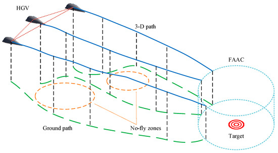
Figure 2.
Multi-HGV cooperative path planning scenario.
To ensure flight safety, the path must avoid no-fly zones on the battlefield. The no-fly zone is separated into a cylindrical region in space to simplify the path cost calculation, i.e., the vehicle can only proceed around the edge of the no-fly zone and cannot cross over it.
In addition, compared with UAVs or other vehicles, HGVs have more stringent requirements on the feasibility of the planned path. Thus, more constraints need to be considered: control variables constraint, heating rate constraint , dynamic pressure constraint , and aerodynamic load constraint . The constraints are shown as follows:
where and are the change rates of the AOA and the bank angle, respectively. is the heating rate parameter, which is in this paper.
In summary, the objective of this paper is to propose a planning method that can quickly find flight paths for multiple HGVs from different beginning points to a predefined FAAC, simultaneously satisfying the terminal constraints Equations (8)~(12) and the process constraints Equations (13)~(15).
3. Analytical Steady Gliding Path Model
The concept of steady gliding entry was originally proposed by a German scientist named Sänger. It is a special trajectory whose flight path angle remains constant and the rate of flight path angle remains zero. This type of trajectory has a gentle altitude variation, which can avoid repeated oscillations of the HGV in the atmosphere, thereby reducing the aerodynamic forces and heat acting on the HGV. Therefore, the steady gliding path is usually the design goal in entry path planning. In this section, an analytical steady gliding path considering terminal altitude and velocity constraints is designed. The HGV’s control variables can be derived according to its current states and the desired terminal states.
The core of entry trajectory planning is to design the longitudinal flight profile of the HGV. Since the altitude and velocity of the HGV are important parameters during the flight process and are directly related to process and terminal constraints, designing the H-V profile is a common trajectory design method. To reduce the force and thermal impact on the HGV, a steadily changed altitude and velocity are desired. This paper designs the H-V profile according to the following two criteria:
Criterion 1 (steady gliding criteria): To avoid jumping in the atmosphere, the HGV is desired to reach the terminal altitude at a constant path angle, that is, steady gliding. This criterion has been repeatedly utilized in the design of guidance methods for reentry gliding vehicles. The applicability of the equilibrium gliding condition is related to the vehicle’s lift performance, according to the literature [29], and the reentry flight process can satisfy this condition for vehicles with large lift-to-drag ratios. According to Ref. [29], the steady gliding condition can be described as:
where is a constant value of the path angle.
Criterion 2 (uniform deceleration criteria): To avoid drastic changes in state, the velocity is expected to change to the terminal value gently. Thus, the velocity profile is designed to be a uniform deceleration motion with a constant drag acceleration. The constant drag acceleration condition was used in the guidance scheme of the space shuttle [30]. Ref. [31] has analyzed that the velocity change rate is close to a constant value in the quasi-equilibrium gliding segment for a vehicle with a large lift-to-drag ratio; the result was verified by simulation as well. The study in ref. [31] demonstrates the feasibility of Criterion 2. The uniform deceleration condition can be described as:
where is a constant value of the drag acceleration.
Dividing Equation (1) by Equation (4), the derivative of altitude relative to velocity can be obtained as
The H-V profile corresponding to Criterion 1 and Criterion 2 can be obtained by substituting Equations (16) and (18) into Equation (19) and integrating it. The designed H-V profile is shown as Equation (20).
where is the terminal altitude, and .
It can be learned from Equation (20) that the H-V profile is a quadratic function. Inequalities and hold because of the monotonic decrease in HGV altitude and velocity. Therefore, the quadratic coefficient of the H-V profile is positive. The schematic diagram of the H-V profile is shown in Figure 3.
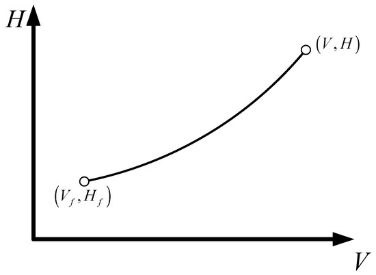
Figure 3.
Schematic diagram of the H-V profile.
As shown in Figure 2, the state of the HGV smoothly transitions from the current state to the terminal state . As the altitude decreases, the altitude change rate also gradually decreases. This is consistent with the entry process of the HGV, indicating the rationality of the designed H-V profile.
Next, the analytical form of the control variables that satisfy the H-V profile will be derived. The range-to-go is defined as the distance between the vehicle’s current position and the target on the Earth’s surface along the great circle arc. Ignoring the deviation between the vehicle’s heading angle and its line-of-sight angle from the target, the following relationship holds:
The altitude and velocity are expected to be given values when range-to-go is zero. So it is necessary to establish relationships between altitude, velocity, and range-to-go. Dividing Equations (1) and (4) by Equation (21), we can obtain the differential equations for altitude and velocity with respect to range-to-go:
Substituting Equations (16) and (18) into Equations (22) and (23), the longitudinal motion equations corresponding to the H-V profile can be described as
Integrating Equation (24), we can obtain
where is the terminal radial distance from the Earth center to the vehicle. Equation (26) is the analytical formula for altitude variation with range-to-go. From Equation (26), the desired constant flight path angle for steady gliding can be calculated at every moment according to the current radial distance , the current range-to-go , and the terminal radial distance .
Substituting Equation (26) into Equation (25) and integrating it, the analytical formula for velocity variation with range-to-go can be obtained as
where is the terminal velocity. According to Equation (28), the desired constant drag acceleration of the vehicle is
According to Equation (7), the AOA is the control variable that affects the magnitude of drag acceleration. The command AOA can be obtained by solving the following equation:
When the command AOA is solved, the lift acceleration can be settled according to Equation (7). HGV adjusts the magnitude of the bank angle to control the component of lift in the longitudinal direction. To smoothly transition the HGV state to the steady gliding state, the command path angle change rate is designed as
where is the control coefficient. The control law (31) can make tending to and the tending to zero.
According to Equation (5), the magnitude of the bank angle is
Equations (30) and (32) are the control variables of the steady gliding flight. At each moment, the desired and can be derived explicitly according to the current state and the terminal constraints.
It should be noted that, although the flight angle and the drag acceleration are expected to be constant as shown in Equations (27) and (29) during flight, they cannot definitely achieve the constant values because of the limitations of the constraints. Thus, the H-V profile has to be recalculated when path planning. The path planning process is shown in Figure 4. The terminal altitude is and the terminal velocity is . The altitude and velocity at time k are denoted as and . is the H-V profile at time k that can be obtained according to Equation (20). Substitute , , and into Equations (27) and (29) to get the command flight path angle and drag acceleration . Then, the control commands at time k can be obtained according to Equations (30) and (32), which are denoted as and . Substitute and into the dynamic model (1)–(6) to obtain the states at time k + 1. In the ideal scenario, and should be on the profile . However, and may deviate from the profile in reality because of control constraints and external disturbances. Repeating the above process until the target is reached, the steady flight path from the beginning point to the target point is obtained.
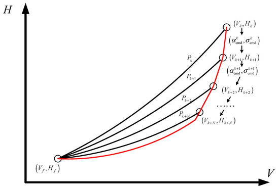
Figure 4.
Schematic diagram of the path planning process.
4. Time-Coordinated A* Path Planning Method Considering No-Fly-Zone Constraints
The A* algorithm is a widely used KPM with the advantages of high computing efficiency and applicability. Node extension and node evaluation are the core procedures of the classic A* algorithm. The schematic of the A* algorithm is shown in Figure 5. From the starting point, many feasible path nodes are extended, from which the node that satisfies the constraints and has the lowest path cost is chosen as the waypoint, and nodes are extended from this waypoint until the target point. The no-fly-zone constraints are considered part of the path cost, so the A* algorithm has a strong ability to avoid no-fly-zones. However, the classic A* algorithm aims to plan the shortest path in the presence of no-fly-zones. The flight time cannot be adjusted. And the classic A* algorithm needs to divide the planning space into grids. The path nodes are selected from the grid points. The HGV dynamic model is not considered when planning. Thus, neither the arrival time constraints nor the HGVs’ path feasibility can be satisfied by the classic A* algorithm.
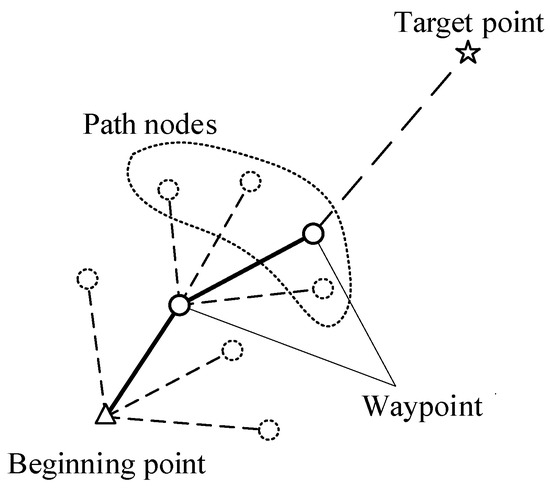
Figure 5.
A* algorithm path planning schematic.
Combining the A* algorithm and the analytical steady gliding path, a time-coordinated A* path planning method for HGV is proposed in this section. The time-coordinated A* path planning method is composed of an improved A* path planning method and an arrival time coordination strategy. The improved A* algorithm is modified as follows: (1) A path node extension method based on the analytical steady path is proposed to ensure that the extended nodes are feasible for the HGVs. (2) An analytical estimation formula for the time-to-go is derived to predict the arrival time corresponding to each path node. (3) A time heuristic function is introduced in the node evaluation to regulate the vehicle’s arrival time as desired. So the improved A* algorithm can generate a feasible path for each HGV while the arrival time meets expectations. In addition, the multi-vehicle arrival time coordination strategy is proposed to determine the desired arrival time online.
4.1. Framework of the Time-Coordinated A* Path Planning Method
The schematic of the time-coordinated A* path planning method is shown in Figure 6. The desired joint arrival time is generated by the arrival time coordination strategy according to all the HGVs’ states. Each HGV separately generates control variables and utilizing the improved A* algorithm. Then, substitute the control variables into the dynamic model to update HGV states. This procedure is repeated until the HGVs arrive at the FAAC.
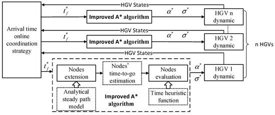
Figure 6.
Schematic of the time-coordinated A* path planning method.
The proposed time-coordinated path planning method is summarized as Algorithm 1:
| Algorithm 1. Time-coordinated A* path planning algorithm |
| INPUT: initial states of n HGVs, extension step , target point, terminal constraints, process constraints, control capacity constraints, no-fly zones constraints. |
| 1: while existing one HGV’s range-to-go larger than the radius of FAAC , do |
| 2: determine the leader HGV and the desired joint arrival time according to all the HGVs’ states based on the arrival-time online coordination method described in Section 4.4. |
| 3: for every HGV do |
| 4: use the path node extension method described in Section 4.1 to obtain a series of reachable path nodes departing from the current waypoint. |
| 5: estimate every node’s time-to-go utilizing the analytical estimation method described in Section 4.2. |
| 6: evaluate every path node’s path cost utilizing the evaluation function described in Section 4.3. |
| 7: select the optimal node with the lowest path cost as the next waypoint, substitute the AOA and bank angle corresponding to the optimal node into the dynamic model to update the states of HGV. |
| 8: end for |
| 9: end while |
| OUTPUT: all the HGVs’ flight paths. |
Next, a detailed introduction to the methods of node expansion, time-to-go estimation, and path evaluation will be, respectively, provided in Section 4.2, Section 4.3, Section 4.4 and Section 4.5.
4.2. Node Extension Method
The node extension is vital for the A* algorithm because it directly determines performance and efficiency. The classic A* algorithm divides the planning space into grids and extends the nodes according to adjacent grid points. It is kinematic-level planning and cannot calculate the control variables or force. So, it is not suitable for HGV, which has strict dynamic and force-thermal constraints.
For solving the HGV path planning problem, the dynamic model should be introduced in node extension. An intuitive idea is to extend nodes through dynamic integration. The selection of control variables during dynamic integration is not arbitrary; otherwise, the terminal constraints are difficult to ensure. In Section 3, the analytical steady gliding path establishes a mapping relationship between terminal constraints and control variables. For a given terminal altitude and terminal velocity , the desired AOA command and the norm of the bank angle command can be derived. Extending nodes using the command control variables can ensure the feasibility of the path and meet terminal constraints.
The path node extension process is shown in Figure 7. Take the terminal altitude and velocity as design variables. The terminal velocity constraint interval is according to Equation (11). Select M points uniformly from the interval to obtain , where and . The superscript i denotes the i-th point in the set . Similarly, select N points uniformly from the terminal altitude interval to obtain , where and . The superscript j denotes the j-th point in the set . Combining and yields the terminal constraint set . The set is composed of terminal constraint pairs . For each , the command control variables and can be obtained through the analytical path planning shown in Section 3. The command bank angle is the absolute value and its sign can be positive or negative. Denote the command control variables with positive and negative symbols as and , respectively. That is, and . The path nodes are extended using the command variables for one-step dynamic integration. The path nodes are denoted as and , where the subscript “+” represents the command bank angle is positive, and the subscript “−” represents the command bank angle is negative. path nodes are obtained for M terminal velocity constraint points and N terminal altitude constraint points. The path nodes satisfy the dynamic constraints and terminal constraints because the analytical steady path and dynamic model are considered.
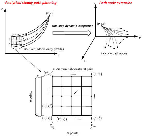
Figure 7.
Schematic of the node extension method.
The specific node extension steps are shown in Algorithm 2:
| Algorithm 2. Node extension |
| INPUT: current states , , , , , , extension step , terminal altitude constraint interval , terminal velocity constraint interval . |
| 1: select N and M points in the terminal altitude constraint interval and terminal velocity constraint interval , respectively, and combine them with each other to form altitude-velocity combinations satisfying the terminal constraint, where (, ), (, ). |
| 2: for every do |
| 3: solve the corresponding flight-path angle according to Equation (27). |
| 4: solve the corresponding drag acceleration according to Equation (29). |
| 5: solve the corresponding AOA according to Equation (30) and solve the corresponding bank angle and according to Equation (32). |
| 6: substitute the AOA and the bank angles into Equations (1)–(6) to obtain the path nodes and . |
| 7: end for |
| OUTPUT: extension nodes and , where , . |
4.3. Analytical Estimation of Time-to-Go
Cooperative path planning requires consideration of the consistency of the arrival time of each vehicle at the FAAC, and accurate estimation of the time-to-go is the key to achieving this purpose.
A time-to-go analytical estimation formula is derived based on the analytical steady path designed in Section 3. From Equation (28), the vehicle velocity is a function related to the range-to-go, so the time-to-go can be expressed as
where is the range-to-go of the terminal, with . According to Criterion 1 and Criterion 2, the flight-path angle and drag acceleration in Equation (33) are constants, so we have
where , , . The flight-path angle and drag acceleration are obtained from Equations (27) and (29), respectively. So the time-to-go can be calculated using Equation (34) once the terminal radial distance from the Earth center to the vehicle , the terminal velocity , and the range-to-go are determined.
4.4. Path Evaluation Method
4.4.1. Evaluation Function
In this paper, we improve on the A* algorithm’s evaluation function, which can consider the arrival time constraint. The evaluation function is defined as:
In Equation (35), is the flight cost, i.e., the range that has been flown from the starting point to the current node. is the penalty function, which is used to remove the nodes that do not satisfy the constraints, whose value will be demonstrated in the next section. is the heuristic function and is designed as:
where is the distance from the current node to the target, is the desired arrival time, is the current time, is the time-to-go estimated by Equation (34), and is the switching coefficient equal to 0 or 1.
The evaluation function describes the cost that the HGV pays when extending a node. Thus, each HGV always takes the node with the smallest evaluation function value as the next waypoint among several extension nodes to generate an optimal path.
Remark 1.
The heuristic function is improved on the A* algorithm by introducing an arrival-time control term and a switching coefficient . If , Equation (35) is the classical evaluation function of the A* algorithm, which can realize single-vehicle path planning with the shortest range. If , Equation (35) makes the path’s arrival time as close to the desired one as possible.
4.4.2. Dealing with Path Node Constraints
To ensure the planned path is feasible and safe, the waypoints selected must satisfy a series of constraints. This section gives the treatment of each constraint during the path planning process.
- (1)
- Control capacity constraints.
During the vehicle’s flight, the AOA and bank angle should be kept within an acceptable range to ensure the vehicle’s stability. Each path node’s magnitude of AOA and bank angle can be derived according to Equation (30), and Equation (32). If they satisfy the constraints shown in Equation (13), the penalty function , otherwise .
Due to HGVs’ maneuverability and control system bandwidth limitations, it is impossible to accurately track the AOA and bank angle commands if the vehicle’s AOA and bank angle change frequently and dramatically, resulting in the vehicle’s inability to fly along the planned path. To improve the feasibility of the path, we incorporated the AOA and bank angle change rate constraints into the path planning process. The AOA variation rate and bank angle variation rate can be calculated as
where and are AOA variation and bank angle variation, respectively.
If the AOA variation rate and bank angle variation rate satisfy the constraints shown in Equation (14), . Otherwise, .
- (2)
- Process constraints.
The heating rate constraint, the dynamic pressure constraint, and the aerodynamic load constraint need to be satisfied during the flight of the HGV, referred to as the process constraint. The equations for heating rate, dynamic pressure, and aerodynamic load are shown in Equation (15).
If the process constraints satisfy Equation (15), . Otherwise, .
- (3)
- Terminal constraints.
During the node extension, the altitude-velocity combinations are selected from the intervals and . Therefore, the terminal altitude and the terminal velocity constraints must be satisfied.
For the terminal heading angle error constraint, the heading angle error corridor [25], which is widely used in the reentry guidance method for HGVs, is used to limit it, as shown in Figure 8. When the range-to-go is large, a larger corridor boundary is selected to enable the vehicle to have strong no-fly zone avoidance and time regulation capability; when the range-to-go decreases, the corridor boundary gradually transitions to the terminal heading angle error constraint value to ensure that the terminal heading angle meets the requirements. If the heading angle error is within the corridor, . Otherwise, .
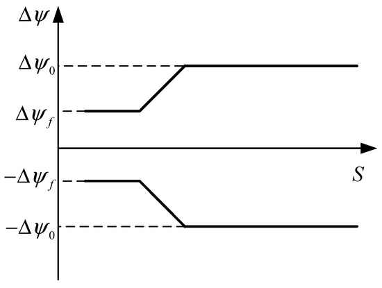
Figure 8.
Heading angle error corridor.
- (4)
- No-fly zone constraints.
Due to the fast flight velocity and large turning radius of the HGV, all the extended nodes are likely in the no-fly zone when the distance from the no-fly zone is close. To avoid such situations, set a minimum safe distance to avoid the no-fly zones. If the distance between the HGV and a no-fly zone is smaller than , take that no-fly zone into account; otherwise, ignore the no-fly zone. As shown in Figure 9, two tangent lines to the no-fly zone are made through the HGV, and if the path node is on the outside of the two tangent lines, the path node satisfies the no-fly zone constraint, and . Otherwise, .
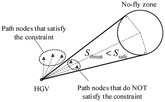
Figure 9.
Dealing with no-fly zone constraints.
4.5. Arrival-Time Online Coordination Method
Determining the vehicles’ arrival time is essential for the multi-vehicle cooperative path planning problem. Most existing studies use offline trajectory optimization before path planning to determine the arrival time range of each vehicle and then select a common arrival time for all the vehicles [22,23,24]. These approaches increase the pre-planning effort exponentially as the vehicle cluster grows, necessitating a considerable quantity of computational resources and computational time, restricting the online deployment of related methods for large-scale clusters.
This research provides an arrival-time online coordination technique based on the idea of leader-follower formation control to address the aforementioned issues. As shown in Figure 10, the time-to-go of each vehicle is estimated using Equation (34), based on the state of each vehicle’s current waypoint. The vehicle with the largest time-to-go is selected as the leader, and the remaining vehicles are followers. The estimated arrival time of the leader vehicle is used as the coordination time.
where is the estimated arrival time of the i-th HGV. is the number of HGVs.
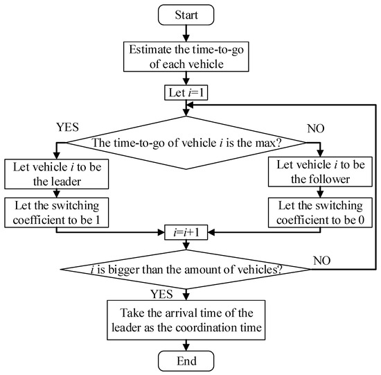
Figure 10.
Arrival-time online coordination method.
Meanwhile, the switching coefficient shown in Equation (36) of the leader is set to 1, and those of the followers to 0. Therefore, the leader tends to find the shortest path, while the followers tend to achieve the same arrival time as the leader, that is how cooperative path planning is realized.
5. Numerical Simulation
5.1. Simulation Conditions
We conducted numerical simulations to verify the proposed method’s effectiveness and superiority. Five cooperative path-planning simulation cases with different conditions were conducted to verify the time-coordinated path-planning method’s effectiveness and superiority. Monte Carlo simulations considering disturbances were conducted to verify the proposed method’s robustness.
A cooperative path planning simulation scenario containing four vehicles was set up, simulating the scenario where different HGVs launch at different times and locations and fly towards the same target point. Due to the focus of this paper being on the reentry flight phase of the HGVs, the ascent stage was ignored, and the simulation began when the HGVs reached an altitude of around 60 km during reentry. The initial states of the HGVs are shown in Table 1.

Table 1.
Initial states of the HGVs.
Three no-fly zones were distributed between the HGV and the target point, simulating the interception range of interceptors. The no-fly zones were modeled as cylindrical shapes in space, and the HGVs need to bypass them laterally to ensure flight safety. The no-fly-zone information is shown in Table 2.

Table 2.
No-fly-zone information.
The longitude and latitude of the target are 60° and 0°, respectively. The constraints to be satisfied by each vehicle are shown in Table 3:

Table 3.
Values of constraints.
Five cases of time-coordination path planning simulation were set up as shown in Table 4. The proposed time-coordinated A* path planning method was used in Case 1 to Case 3. However, different requirements were considered in the three cases. In Case 1, neither the time-coordinated requirement nor the no-fly-zone constraint were considered. In Case 2, only the no-fly-zone constraint was considered. In Case 3, both the time-coordinated requirement and the no-fly-zone constraint were considered. Case 4 and Case 5 used the hp-AGPM [18] and the QEGC-based method [25] as comparisons, which are existing DPMs satisfying the time-coordinated requirement. The hp-AGPM and QEGC-based methods need to schedule the arrival time of each vehicle before the simulation. In Case 4 and Case 5, the arrival time of each HGV was set to be 1560 s. Case 6 set up a simulation example to verify the advantages of the time-coordinated A* path planning method in the presence of online maneuvering. The simulation conditions are the same as in Case 3, except that the HGV1 maneuvers at a constant AOA of 15 deg and a constant bank angle of 40 deg within 1000–1030 s.

Table 4.
Simulation conditions for the cases.
Moreover, the Monte-Carlo simulation was conducted to verify the proposed method’s robustness against disturbances. The nominal simulation conditions were the same as in Case 3, and the disturbances are shown in Table 5.

Table 5.
Disturbances of Monte-Carlo simulation.
5.2. Time-Coordinated Path Planning Simulations
The statistics of crucial indicators, which are arrival time (AT), terminal altitude (TA), terminal velocity (TV), terminal heading angle error (THAE), maximum dynamic pressure (MDP), maximum heating rate (MHR), maximum aerodynamic load (MAL), and calculation time (CT), are shown in Table 6.

Table 6.
The statistics of crucial indicators.
The ground tracks in Case 1 and Case 2 are shown in Figure 11 and Figure 12. Comparing the simulation results in Case 1 and Case 2, Case 1 did not consider avoiding the no-fly zones, and the vehicles’ paths pass through the no-fly zones directly; after introducing the no-fly-zone constraints in Case 2, the vehicles can successfully avoid the no-fly zones, which verifies that the algorithm of this paper can effectively avoid the threat of no-fly zones.
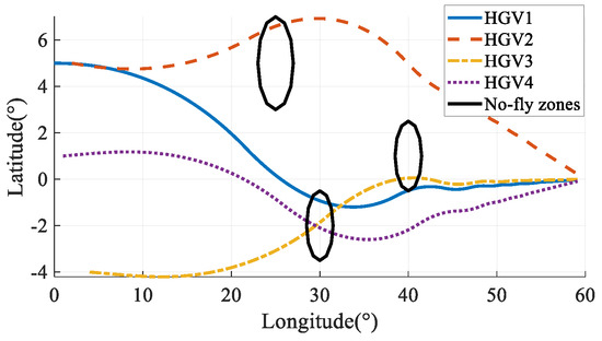
Figure 11.
Ground tracks in Case 1.
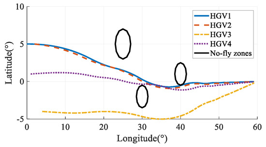
Figure 12.
Ground tracks in Case 2.
The simulation results in Case 3 are shown in Figure 13, Figure 14, Figure 15, Figure 16, Figure 17, Figure 18, Figure 19, Figure 20, Figure 21, Figure 22, Figure 23 and Figure 24. From the simulation results, it can be seen that all HGVs avoid the no-fly zones and meet both terminal and process constraints. The altitude and velocity of the HGVs transit to the terminal states smoothly without oscillation. The flight path angle of each HGV approximately maintains a constant value, and the altitude-velocity profiles shown in Figure 23 are approximate to a quadratic function, which is consistent with the analytical steady gliding path. The AOA transits from the maximum value to the near-optimal lift-to-drag ratio AOA, which is 10 deg in this paper. The changing trend is consistent with the commonly used AOA profile [29]. The simulation results prove that the analytical steady gliding path is feasible for HGV.
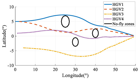
Figure 13.
Ground tracks in Case 3.
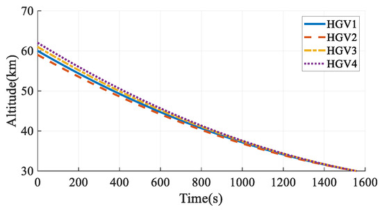
Figure 14.
Altitudes in Case 3.
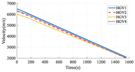
Figure 15.
Velocities in Case 3.
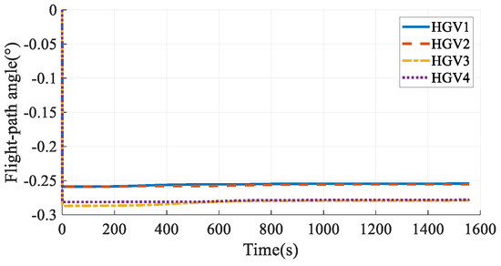
Figure 16.
Flight-path angles in Case 3.
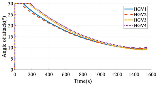
Figure 17.
Angles of attack in Case 3.
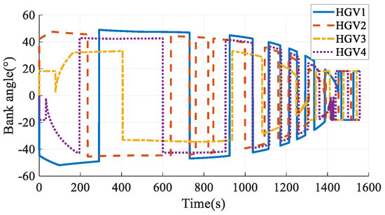
Figure 18.
Bank angles in Case 3.
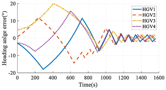
Figure 19.
Heading angle errors in Case 3.
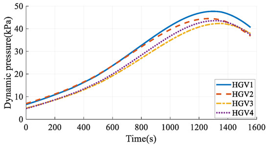
Figure 20.
Dynamic pressures in Case 3.
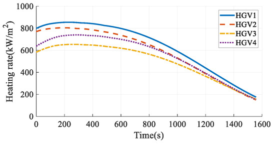
Figure 21.
Heating rates in Case 3.
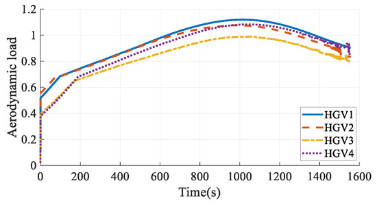
Figure 22.
Aerodynamic loads in Case 3.
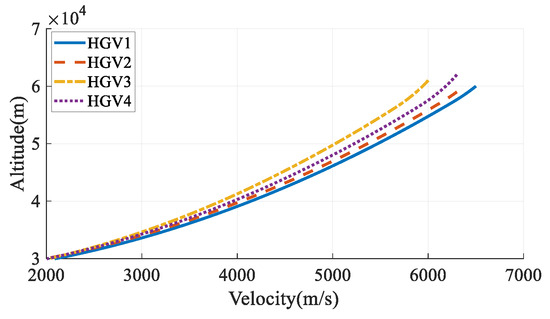
Figure 23.
Altitude-velocity profile in Case 3.
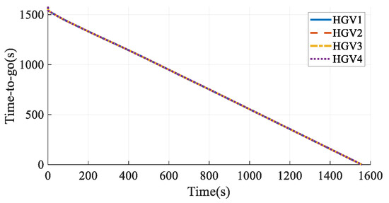
Figure 24.
Time-to-go estimation in Case 3.
Comparing the simulation results in Case 2 and Case 3, when time coordination is not considered, the maximum arrival time error of the vehicle is 21.91 s; when time coordination is considered, the arrival time error of the vehicle is 0.05 s, indicating that the time coordination of the HGVs is achieved. The vehicles’ paths are smooth and satisfy all the constraints, which verifies the effectiveness of the cooperative path planning method proposed in this paper.
The simulation results in Case 4 are shown in Figure 25, Figure 26, Figure 27, Figure 28, Figure 29, Figure 30, Figure 31, Figure 32, Figure 33 and Figure 34. Comparing the simulation results in Case 3 and Case 4, when considering the time-coordination requirement, both the method in this paper and the hp-AGPM can plan the path that meets the constraints. However, the path in Case 3 is smoother, and the angles of attack and bank angles change more gently, which is more conducive to the tracking and guidance of HGVs. At the same time, the maximum heating rate and maximum aerodynamic load in Case 3 are smaller than those in Case 4, so the force and thermal influence on the vehicles are smaller, which reflects the advantages of steady gliding. In addition, the path planning time in Case 3 is shorter. It is worth noting that the process of determining the cooperative arrival time through preliminary trajectory optimization is not considered in Case 4. Hence, the calculation time of the method proposed in this paper is much smaller than that of existing methods, which has a broader application prospect for the online path planning problem of large-scale vehicle clusters. In comparison, the method described in this paper can plan smoother paths, reduce the force-thermal influence, and have a shorter calculating time, which fully reflects the superiority of the time-coordinated A* path planning method proposed in this paper.
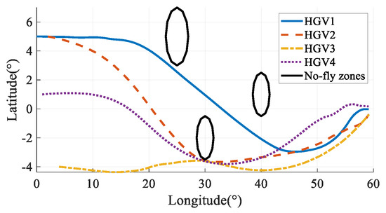
Figure 25.
Ground tracks in Case 4.
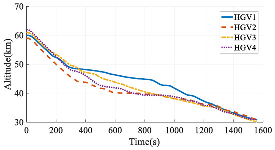
Figure 26.
Altitudes in Case 4.
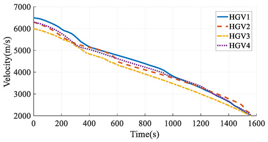
Figure 27.
Velocities in Case 4.
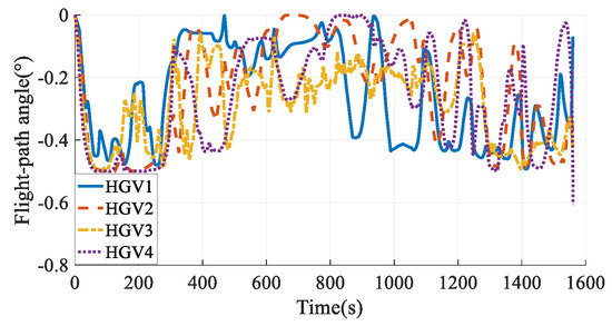
Figure 28.
Flight-path angles in Case 4.
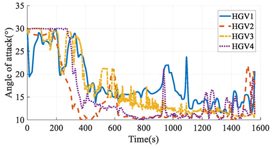
Figure 29.
Angles of attack in Case 4.
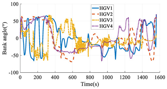
Figure 30.
Bank angles in Case 4.
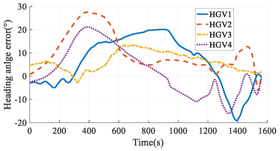
Figure 31.
Heading angle errors in Case 4.
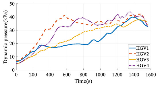
Figure 32.
Dynamic pressures in Case 4.
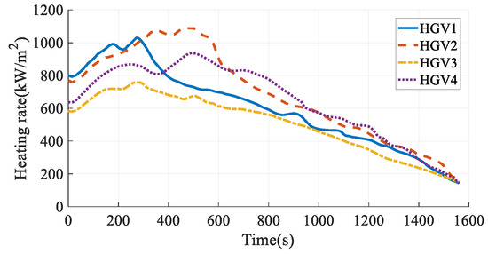
Figure 33.
Heating rates in Case 4.
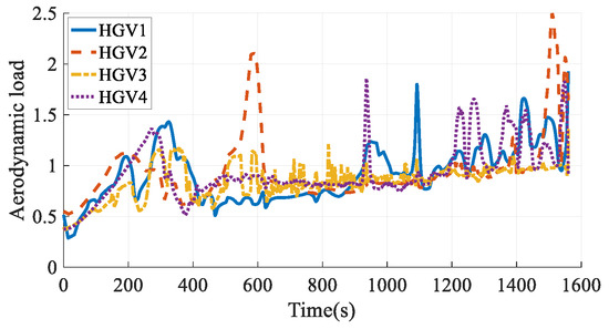
Figure 34.
Aerodynamic loads in Case 4.
The simulation results in Case 5 are shown in Figure 35, Figure 36, Figure 37, Figure 38, Figure 39 and Figure 40. Comparing the simulation results in Case 3 and Case 5, the two methods can both satisfy the time-coordination requirement. The path planning time in Case 5 is a bit shorter than in Case 3. However, because the QEGC-based method did not consider avoiding the no-fly zone, HGV2 and HGV4 passed through the no-fly zone. The HGVs in Case 3 successfully bypassed the no-fly zones. The simulation results show that the method proposed in this paper has a strong ability to avoid no-fly zones.
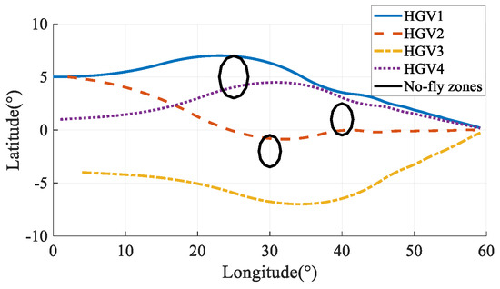
Figure 35.
Ground tracks in Case 5.
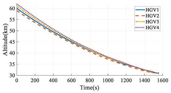
Figure 36.
Altitudes in Case 5.
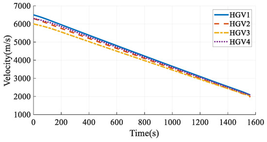
Figure 37.
Velocities in Case 5.
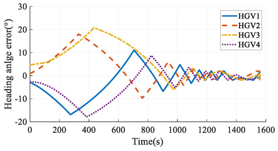
Figure 38.
Heading angle errors in Case 5.
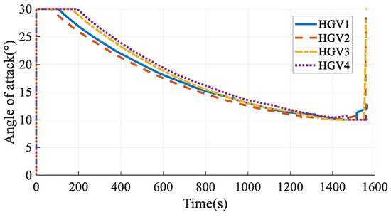
Figure 39.
Angles of attack in Case 5.
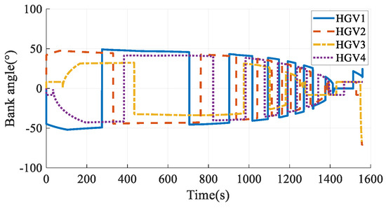
Figure 40.
Bank angles in Case 5.
The simulation results in Case 6 are shown in Figure 41, Figure 42, Figure 43, Figure 44, Figure 45, Figure 46, Figure 47, Figure 48, Figure 49 and Figure 50. From the simulation results, it can be seen that the arrival time of HGV1 grows to 1566.21 s after maneuvering from 1557.01 s. Benefiting from the arrival-time online coordination strategy, the arrival times of the other HGVs increase correspondingly, and the arrival time error of the HGVs is 0.51 s in the final. Meanwhile, the paths satisfy the terminal constraints, process constraints, and no-fly-zone constraints. The simulation results illustrate that the time-coordinated A* path planning method has online adjustment capabilities that can deal with sudden threats.
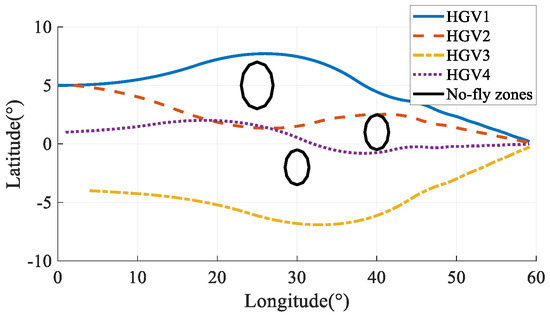
Figure 41.
Ground tracks in Case 6.
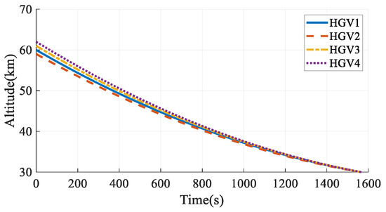
Figure 42.
Altitudes in Case 6.
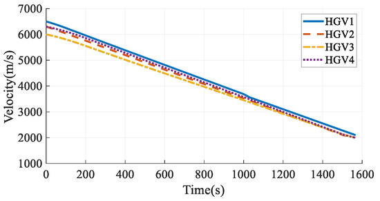
Figure 43.
Velocities in Case 6.
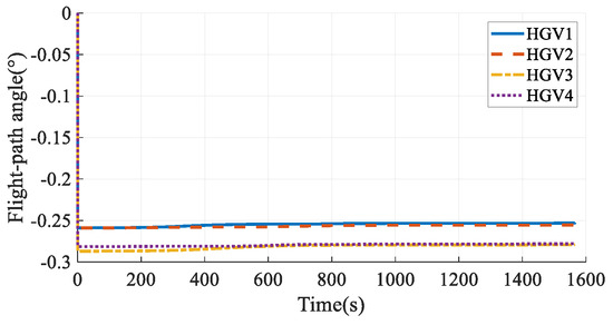
Figure 44.
Flight-path angles in Case 6.
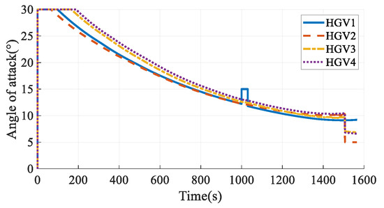
Figure 45.
Angles of attack in Case 6.
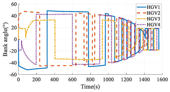
Figure 46.
Bank angles in Case 6.
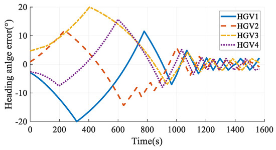
Figure 47.
Heading angle errors in Case 6.
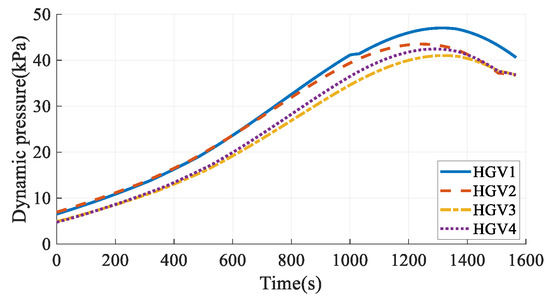
Figure 48.
Dynamic pressures in Case 6.
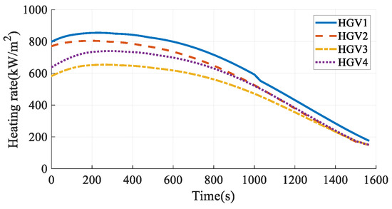
Figure 49.
Heating rates in Case 6.
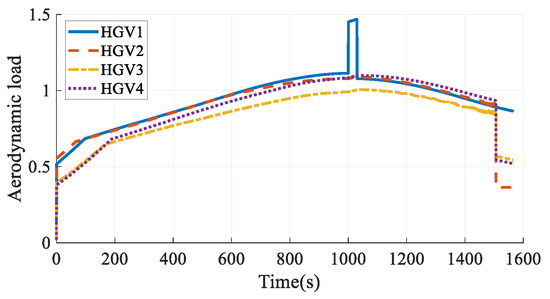
Figure 50.
Aerodynamic loads in Case 6.
5.3. Monte-Carlo Simulation
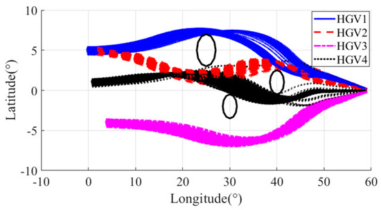
Figure 51.
Ground tracks.
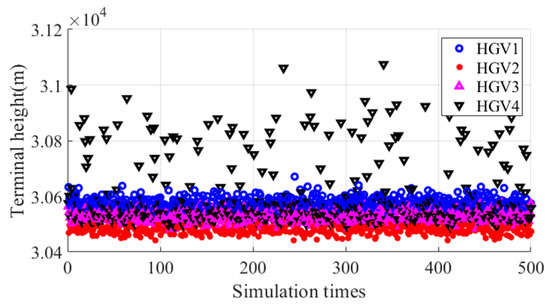
Figure 52.
Terminal altitude.
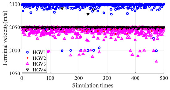
Figure 53.
Terminal velocity.
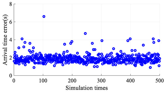
Figure 54.
Arrival time error.
The simulation results illustrated that all the paths bypassed the no-fly zones, which are the black circles in Figure 51. Most of the terminal altitudes and velocities were within the required interval. The maximum deviation from the terminal limitation of terminal altitude and velocity was 83 m and 25 m/s, respectively. The maximum arrival time error was 6.6 s, and the average arrival time error was 1.9 s.
6. Conclusions
This paper proposes an online time-coordinated A*path planning method for HGVs that combines the KPM and DPM. This method combines the efficiency and strong no-fly-zone processing capability of KPM, as well as the advantage of DPM meeting dynamic constraints. An analytical steady flight DPM is proposed first based on a quadratic function-type altitude-velocity profile, which can derive the control commands explicitly according to the desired terminal altitude and velocity. Based on this, the time-coordinated path planning method is designed by combining the analytical steady glide DPM with the framework of the A* algorithm, which is a classic KPM. An improved path extension method of the A* algorithm is designed by introducing the analytical steady glide DPM. The path extension method can ensure that the path satisfies the dynamic constraints, which solves the problem that the classic A* algorithm cannot be applied to HGVs. A path evaluation function with a time control term and a penalty function is designed to satisfy the time coordination requirement and no-fly-zone constraints. An online time-coordinated strategy is proposed to determine a commonly desired arrival time for several HGVs online. It can avoid the need to determine the arrival time in advance. The HGVs can adjust the arrival time according to the analytical estimation of flight times. Thus, the HGVs can deal with sudden threats. It makes the proposed method have stronger prospects for online applications. The simulation results show that this method can plan the time-coordinated path of multiple HGVs and satisfy terminal constraints, process constraints, control capacity constraints, and no-fly-zone constraints. Compared with the trajectory optimization method, the path planned by this method is smoother, the maximum heating rate and maximum aerodynamic load are significantly reduced, and the calculation time is also greatly reduced, which thoroughly verifies the effectiveness and superiority of this method.
It should be acknowledged that this paper still has limitations. This paper takes the terminal velocity and altitude as design variables, which causes the terminal velocity and altitude not to be given values. Instead, the terminal velocity and altitude are only limited to a given range. Thus, there may be velocity and altitude differences among different HGVs when arriving at FAAC. This issue may be addressed by dynamically adjusting the range of terminal constraint limitations in future research.
Author Contributions
Methodology, Z.X. and C.W.; Validation, Z.X.; Investigation, N.C. and Y.G.; Writing—original draft, Z.X.; Writing—review & editing, C.W. and Y.G.; Supervision, C.W. and N.C. All authors have read and agreed to the published version of the manuscript.
Funding
This research was funded by the National Natural Science Foundation of China, grant number 62373124.
Data Availability Statement
Data are contained within the article.
Conflicts of Interest
The authors declare no conflicts of interest.
References
- Liang, Z.; Ren, Z.; Li, Q.; Chen, J. Decoupled three-dimensional entry trajectory planning based on maneuver coefficient. Proc. Inst. Mech. Eng. Part G J. Aerosp. Eng. 2017, 231, 1281–1292. [Google Scholar] [CrossRef]
- Li, W.; Cassandras, C.G. Centralized and distributed cooperative Receding Horizon control of autonomous vehicle missions. Math. Comput. Model. 2006, 43, 1208–1228. [Google Scholar] [CrossRef]
- Shen, L.; Chen, J.; Wang, N. Overview of air vehicle mission planning techniques. Acta Aeronaut. Astronaut. Sin. 2014, 35, 593–606. (In Chinese) [Google Scholar]
- Luo, M.; Hou, X.; Yang, J. Surface Optimal Path Planning Using an Extended Dijkstra Algorithm. IEEE Access 2020, 8, 147827–147838. [Google Scholar] [CrossRef]
- Zhu, D.-D.; Sun, J.-Q. A New Algorithm Based on Dijkstra for Vehicle Path Planning Considering Intersection Attribute. IEEE Access 2021, 9, 19761–19775. [Google Scholar] [CrossRef]
- Zhang, L.; Lin, Z.; Wang, J.; He, B. Rapidly-exploring Random Trees multi-robot map exploration under optimization framework. Robot. Auton. Syst. 2020, 131, 103565. [Google Scholar] [CrossRef]
- Mandloi, D.; Arya, R.; Verma, A.K. Unmanned aerial vehicle path planning based on A* algorithm and its variants in 3d environment. Int. J. Syst. Assur. Eng. Manag. 2021, 12, 990–1000. [Google Scholar] [CrossRef]
- Tang, B.; Hirota, K.; Wu, X.; Dai, Y.; Jia, Z. Path Planning Based on Improved Hybrid A* Algorithm. J. Adv. Comput. Intell. Intell. Inform. 2021, 25, 64–72. [Google Scholar] [CrossRef]
- Chen, J.; Li, M.; Yuan, Z.; Gu, Q. An Improved A* Algorithm for UAV Path Planning Problems. In Proceedings of the 2020 IEEE 4th Information Technology, Networking, Electronic and Automation Control Conference (ITNEC), Chongqing, China, 12–14 June 2020; IEEE: Piscataway, NJ, USA, 2020; pp. 958–962. [Google Scholar]
- Roberge, V.; Tarbouchi, M.; Labonté, G. Comparison of parallel genetic algorithm and particle swarm optimization for real-time UAV path planning. IEEE Trans. Ind. Inform. 2012, 9, 132–141. [Google Scholar] [CrossRef]
- Fu, Y.; Ding, M.; Zhou, C. Phase angle-encoded and quantum-behaved particle swarm optimization applied to three-dimensional route planning for UAV. IEEE Trans. Syst. Man Cybern.-Part A Syst. Hum. 2011, 42, 511–526. [Google Scholar] [CrossRef]
- Zhang, X.; Xia, S.; Zhang, T.; Li, X. Hybrid FWPS cooperation algorithm based unmanned aerial vehicle constrained path planning. Aerosp. Sci. Technol. 2021, 118, 107004. [Google Scholar] [CrossRef]
- Tian, M.X. Unmanned aerial vehicle path planning with improved ant colony algorithm. Comput. Sci. Appl. 2020, 10, 1900–1907. [Google Scholar]
- Luo, G.-C.; Yu, J.-Q.; Mei, Y.-S.; Zhang, S.-Y. UAV path planning in mixed-obstacle environment via artificial potential field method improved by additional control force. Asian J. Control 2015, 17, 1600–1610. [Google Scholar] [CrossRef]
- Hu, Y.; Yao, Y.; Ren, Q.; Zhou, X. 3D multi-UAV cooperative velocity-aware motion planning. Future Gener. Comput. Syst. 2020, 102, 762–774. [Google Scholar] [CrossRef]
- Wu, W.; Wang, X.; Cui, N. Fast and coupled solution for cooperative mission planning of multiple heterogeneous unmanned aerial vehicles. Aerosp. Sci. Technol. 2018, 79, 131–144. [Google Scholar] [CrossRef]
- Ruchti, J.; Senkbeil, R.; Carroll, J.; Dickinson, J.; Holt, J.; Biaz, S. Unmanned aerial system collision avoidance using artificial potential fields. J. Aerosp. Inf. Syst. 2014, 11, 140–144. [Google Scholar] [CrossRef]
- Han, P.; Shan, J.; Meng, X. Re-entry trajectory optimization using an hp-adaptive Radau pseudospectral method. Proc. Inst. Mech. Eng. Part G J. Aerosp. Eng. 2013, 227, 1623–1636. [Google Scholar] [CrossRef]
- Feng, X.; Lv, Y.; Gao, Y.; Li, Y. Adaptive Radau pseudo-spectral optimization for descending trajectory of a hypersonic cruise vehicle. Aerosp. Syst. 2020, 3, 275–286. [Google Scholar] [CrossRef]
- Wu, Y.; Deng, J.; Li, L.; Su, X.; Lin, L. A hybrid particle swarm optimization-gauss pseudo method for reentry trajectory optimization of hypersonic vehicle with navigation information model. Aerosp. Sci. Technol. 2021, 118, 107046. [Google Scholar] [CrossRef]
- Liu, X.; Shen, Z.; Lu, P. Entry trajectory optimization by second-order cone programming. J. Guid. Control Dyn. 2016, 39, 227–241. [Google Scholar] [CrossRef]
- Liu, Z.; Zheng, W.; Wang, Y.; Wen, G.; Zhou, X.; Li, Z. A cooperative guidance method for multi-hypersonic vehicles based on convex optimization. In Proceedings of the 2020 Chinese Automation Congress (CAC), Shanghai, China, 6–8 November 2020; IEEE: Piscataway, NJ, USA, 2020; pp. 2251–2256. [Google Scholar]
- Liu, Z.; Lu, H.R.; Zheng, W.; Wen, G.; Wang, Y.; Zhou, X. Rapid time-coordination trajectory planning method for multi-glide vehicles. Acta Aeronaut. Astronaut. Sin. 2021, 42, 524497. (In Chinese) [Google Scholar]
- Li, Z.; He, B.; Wang, M.; Lin, H.; An, X. Time-coordination entry guidance for multi-hypersonic vehicles. Aerosp. Sci. Technol. 2019, 89, 123–135. [Google Scholar] [CrossRef]
- Guo, Y.; Li, X.; Zhang, H.; Wang, L.; Cai, M. Entry guidance with terminal time control based on quasi-equilibrium glide condition. IEEE Trans. Aerosp. Electron. Syst. 2019, 56, 887–896. [Google Scholar] [CrossRef]
- Liu, X.; Li, X.; Wang, X. Analytical Cooperative Reentry Guidance for Hypersonic Glide Vehicles. J. Astronaut. 2023, 44, 731–742. [Google Scholar]
- Liang, Z.; Lv, C.; Zhu, S. Lateral Entry Guidance with Terminal Time Constraint. IEEE Trans. Aerosp. Electron. Syst. 2022, 59, 2544–2553. [Google Scholar] [CrossRef]
- Yu, J.; Dong, X.; Li, Q.; Ren, Z.; Lv, J. Cooperative guidance strategy for multiple hypersonic gliding vehicles system. Chin. J. Aeronaut. 2020, 33, 990–1005. [Google Scholar] [CrossRef]
- Shen, Z.; Lu, P. On-board entry trajectory planning for sub-orbital flight. Acta Astronaut. 2005, 56, 573–591. [Google Scholar] [CrossRef]
- Harpold, J.C.; Graves, C.A., Jr. Shuttle entry guidance. Am. Astronaut. Soc. 1978, 27, 239–268. [Google Scholar]
- Jia, S.; Wang, X.; Li, F.; Wang, Y. Distributed analytical formation control and cooperative guidance for gliding vehicles. Int. J. Aerosp. Eng. 2020, 2020, 8826968. [Google Scholar] [CrossRef]
Disclaimer/Publisher’s Note: The statements, opinions and data contained in all publications are solely those of the individual author(s) and contributor(s) and not of MDPI and/or the editor(s). MDPI and/or the editor(s) disclaim responsibility for any injury to people or property resulting from any ideas, methods, instructions or products referred to in the content. |
© 2024 by the authors. Licensee MDPI, Basel, Switzerland. This article is an open access article distributed under the terms and conditions of the Creative Commons Attribution (CC BY) license (https://creativecommons.org/licenses/by/4.0/).