1. Introduction
Aircraft battle damage assessment assesses the extent of an aircraft battle injury, the time and resources required to repair it, the repair work to be accomplished, and the operational capability after repair. Battle damage assessment is the prerequisite and necessary condition for battle damage repair. In modern local warfare, the helicopter fuselage is vulnerable to damage caused by gunfire during low-altitude operations, and rapid assessment of projectile wounds is a prerequisite for helicopter battle wound repair. Therefore, the analysis efficiency of helicopter fuselage damage directly affects the efficiency of battlefield rapid repair.
Neural network and decision tree regression models were trained by Pushkar through finite element simulations and applied to predict the penetration analysis of projectiles on laminates [
1]. Amin used FEM to compute the high-speed impact of the projectile and studied the impact damage effect characteristics of mass, diameter, warhead shape, and properties of ceramic materials [
2]. Senthil and Iqbal found that monolithic aluminum targets have higher ballistic performance than double-layered in-contact targets against ogive-nosed projectiles [
3]. Wei et al. [
4] assessed the effectiveness of monolithic and layered steel targets in single, double, triple, and quadruple-layered configurations against cylindrical blunt-nosed steel projectiles. Mohammad et al. [
5] and Gupta et al. [
6] investigated the ballistic resistance of monolithic and layered plate targets of aluminum 1100-H12 subjected to a nosed projectile at oblique incidence angles. This study showed that the ballistic limit of all targets increases with an increase in inclination. Additionally, Mondal et al. [
7] and Fars et al. [
8] investigated the ballistic behavior of the conventional aluminum alloy. It showed that the failure mode changes from plugging to dicing as the velocity of the projectiles increases. Those FEM-based numerical simulations focused mainly on the residual velocity and damage form of simple flat plate models but not on complex models, such as helicopter fuselages. Thus, it is difficult to efficiently analyze and evaluate the projectile injury of helicopter fuselage with complex structures in multi-projectile environments due to its huge computational time.
Based on the initial velocity of the fragment and residual velocity, Cheng [
9] established regression equations to obtain the ballistic limiting velocity of the fragment. The effect of dimensionless projectile length and dimensionless target thickness on the ballistic limiting velocity was also investigated. Liu [
10] applied the trust domain method to obtain the model coefficients and establish the ballistic terminal velocity calculation model. Gao [
11] developed a theoretical model for the penetration resistance surface of tungsten spheres, pillars, and blocks on armor steel plates. This model was based on both theoretical and experimental studies on the penetration performance of combat prefabricated breakers. The equation for the limiting penetration velocity and the limiting penetration velocity of three typical prefabricated breakers were also developed. The study considered the effect of target attitude on the limiting penetration velocity to provide a comprehensive analysis. Zhao [
12] analyzed the force characteristics of prefabricated fragments intruding through homogeneous armor steel, derived the equation for the limiting penetration velocity of prefabricated pieces, and obtained the correction coefficients for the limiting penetration velocity calculation equation by combining the live-fire drive test and the ballistic gun simulation review test. The ballistic limiting velocity of projectiles penetrating materials was derived from test data, while residual velocity and damage characteristics were still missing. Furthermore, tests were limited to structural parts, and the material and structural properties were significantly different from those of helicopter fuselages. In actual war, ground artillery quickly fires multiple projectiles, which will form a multi-shell encircle around the helicopter space. The encircling circle is normally distributed in 3D space. Therefore, it is difficult to analyze and evaluate the projectile injury of helicopter fuselage structures in complex multi-projectile environments.
Given the importance of the problem at hand, an efficient analysis method for helicopter fuselage projectile injury is proposed by coupling a projectile penetration theory with a projectile collision calculation model, which is then compared with experiments to validate its accuracy. Projectile impact coordinates, residual velocity, and fuselage damage area under multiple projectile strikes are then investigated.
The efficient method can describe the situation of a helicopter being hit by multiple projectiles in actual war. When the helicopter is fighting at a low altitude, the ground artillery fires multiple projectiles, and the engineer can generate the distribution of multiple projectiles around the helicopter according to the relative position of the gun and the helicopter by this method. Then, the possible strike point position and projectile incident situation of the helicopter in the multi-projectile encircle are obtained by rapid simulation calculation. Finally, the damaged area of the striking point is quickly analyzed according to the empirical formula. It allows engineers to quickly determine the damage to the helicopter.
3. Results and Discussion
3.1. Verification of the Method
Verification with Experiment
The experimental data in the references [
16] are selected to verify the accuracy of the proposed method. The experiment used a two-stage air gun system to launch projectiles. The projectile diameter is 12.7 mm, the length of the cylindrical section of the projectile is 75 mm, the front end is a hemispherical head, the mass is 78 g, and the material is steel.
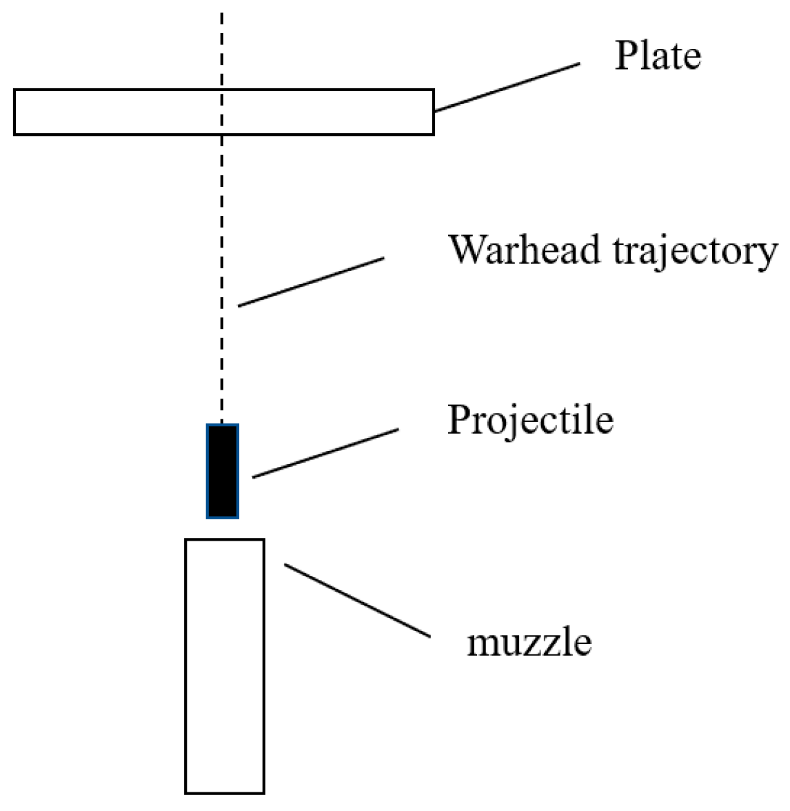
Figure 1 shows the shape of the projectile. The test target plate is 800 mm in length, 440 mm wide, 5 mm thick, and made of 2024 aluminum alloy.
Figure 2 shows the experiment device. The ejection direction remains normal to the target plate, and the initial velocity is 905.7 m/s, 781.6 m/s, and 451.6 m/s, respectively. The material parameters of the projectile and target plate are shown in
Table 1 and
Table 2, respectively.
Table 3 and
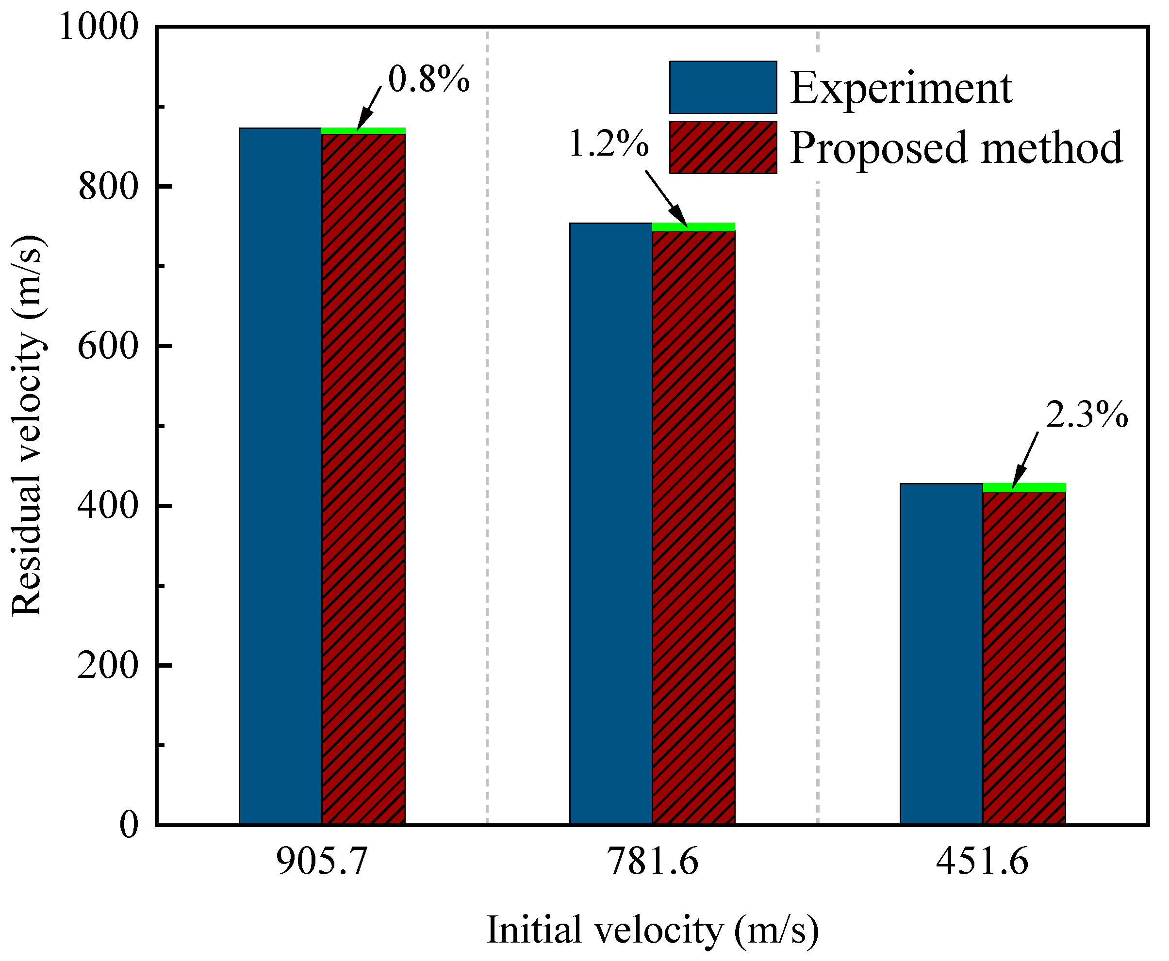
Figure 3 show the projectile residual velocity after the high-speed impact. Under the same incidence angle and thickness, the residual velocities of the projectiles with different initial velocities predicted by the proposed method are in good agreement with the experimental measurements, and the maximum error is 2.3%. It shows that the proposed method for helicopter fuselage projectile wounds can accurately predict the residual velocity of the projectile at different initial velocities.
3.2. Strike Point and Damage Area Characteristics of Helicopter Fuselage
The proposed method for helicopter fuselage bullet damage consists of two parts. The projectile impact point is calculated according to the 3D helicopter model. Then, the residual velocity and damage area after projectile impact are calculated based on the helicopter’s structural parameters, including thickness and material at the impact point, so that the impact of the body structure can be reflected.
First, the simulation of a specific type of helicopter projectile damage, the projectile body diameter of 12.7 mm, the projectile length of 75 mm, and the projectile speed of 1000 m/s. The normrnd function randomly generates 50 space projectile points around the helicopter model according to the normal distribution of anti-aircraft projectile points.
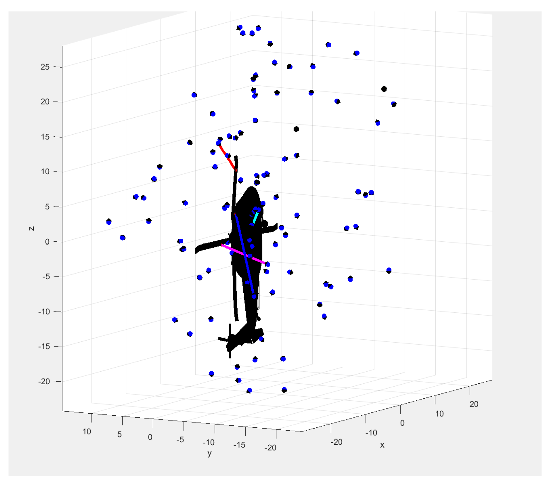
Figure 4 shows the normal distribution of projectiles in the 3D space around the helicopter. Red circle indicates normal distribution ranges, and blue dots indicate randomly projectile points.
Figure 5 shows the visualization of the strike simulation in the numerical program.
Among the 50 randomly generated projectile points, there are six strike points that will strike the helicopter fuselage. Those coordinates are (215.03, 46.74, −23.26), (113.67, 47.93), (248.88, 54.16, 188.23), (308.52, 50.20, −242.55), (48.52, 64.92, −74.00), and (236.57, 54.80, 183.41). The angles between the incident ray and the normal of the collision point surface are 43.51°, 28.99°, 77.01°, 50.53°, 8.16°, and 87.71°, respectively.
Subsequently, the proposed method is used to analyze the degree of impact of a projectile injury at six collision points. The fuselage material is aluminum alloy 2A50, and the material parameters are shown in
Table 4.
The medium damage area is the maximum envelope area of the damaged and destroyed unit after the fuselage surface is hit by the projectile.
Table 5 shows the residual velocity and damage area at different incidence angles calculated by the proposed method.
3.3. Damage Characteristics of Helicopter Fuselage
3.3.1. Helicopter Fuselage Modeling
By coupling the ABAQUS software and the proposed method, the damage process and damage form of the helicopter fuselage at six strike points are further analyzed. A 3D model of a helicopter is established based on SOLIDWORKS software. The fuselage size is 15 m in length and 2.4 m wide; the fuselage thickness is 4 mm; and the material is a 2A50 aluminum alloy. The high-speed impact is relative motion between the macro-object collisions, which can lead to serious macro-object deformation and destruction. To analyze the inclination angle and material factors, the projectile diameter is 12.7 mm, the length of the cylindrical section of the projectile is 75 mm, the front end is a hemispherical head, the mass is 75 g, and the material is steel. A projectile velocity of 1000 m/s is used.
Figure 6 shows the 3D model of the helicopter.
Based on HYPERMESH software (Altair, Troy, MI, USA), the helicopter fuselage mesh is established. The mesh element is hex8 mesh with a cell mesh of about 4 mm, and the mesh number is 2.2 × 10
5.
Figure 7 shows the helicopter fuselage grid.
Based on the coordinates of the six impact points, the angle of incidence, and the projectile injury characteristics calculated by the proposed method in this paper, the projectile and the helicopter fuselage are assembled in the assembly module according to the corresponding incidence points and angles of incidence. ABAQUS/Explicit is selected to calculate the impact with the boundary conditions of rear fuselage solid support and an initial velocity of 1000 m/s.
3.3.2. Comparison of Proposed Method and FEM
The damage area is the maximum envelope area of the damaged and destroyed unit. In finite element analysis, the damage unit can be determined according to the damage value of the material, and the damage area can be obtained by calculating the envelope area of the damage area.
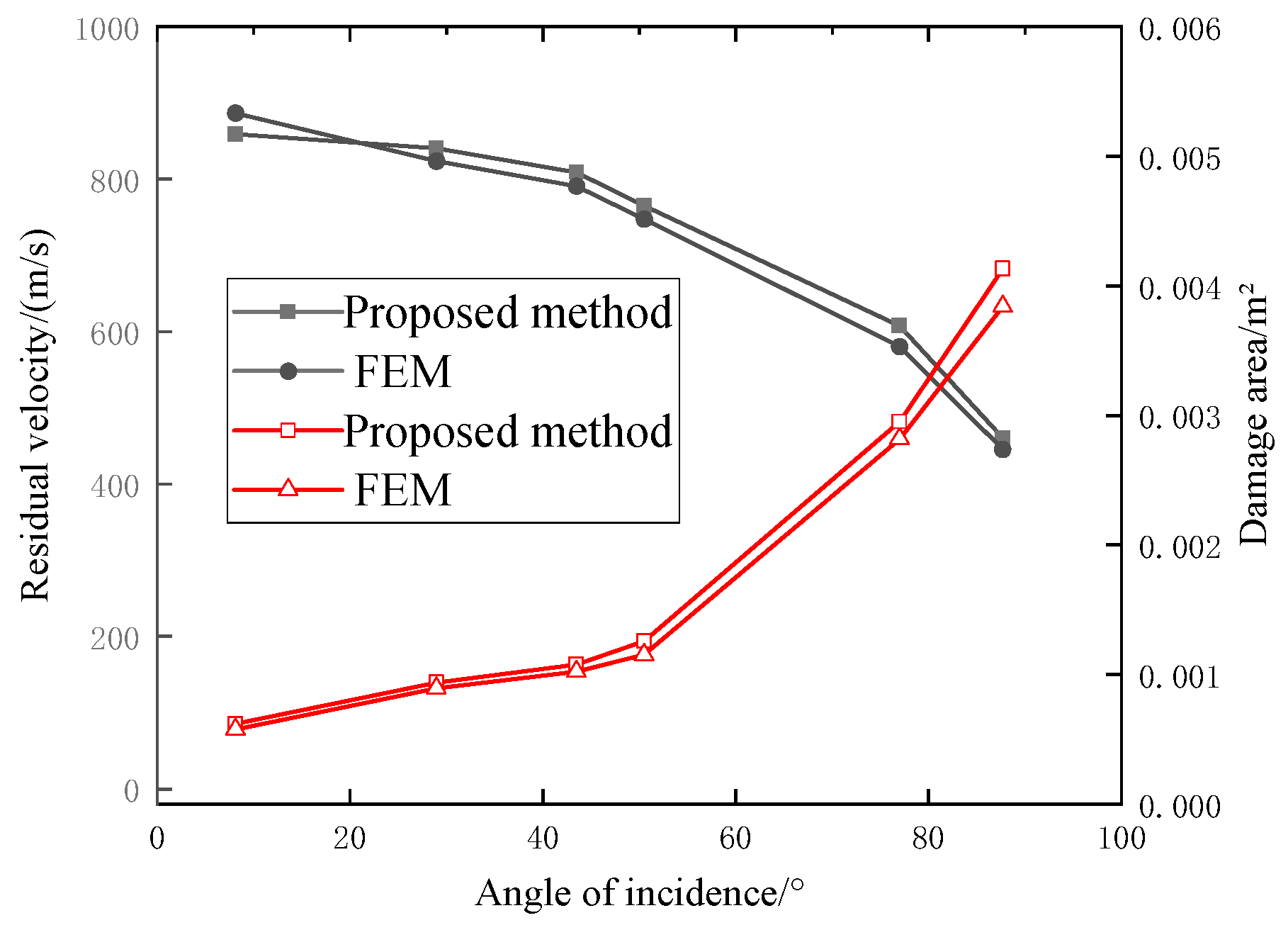
Table 6 and
Figure 8 show a comparison of the residual velocity and damage area. The projectile residual velocity and damage area calculated by the proposed method and FEM are in good agreement. The percentage differences between the residual velocity of the proposed method and the residual velocity of the FEM for the six impact points are 3.1%, 2.0%, 2.20, 2.26%, 4.7%, and 3.4%, respectively. The percentage differences between the damaged area of the proposed method and the damaged area of the FEM are 8%, 5.02%, 5.88%, 9.56%, 4.88%, and 7.97%, respectively. In the case of six different striking points, the residual velocity of the proposed method is less than 4.7%, which compares with the residual velocity of the projectile in the FEM. The damage area of the proposed method is less than 9.56%, which compares with the damage area of the FEM. The results indicate that the proposed method of projectile injury can obtain approximate results with the FEM.
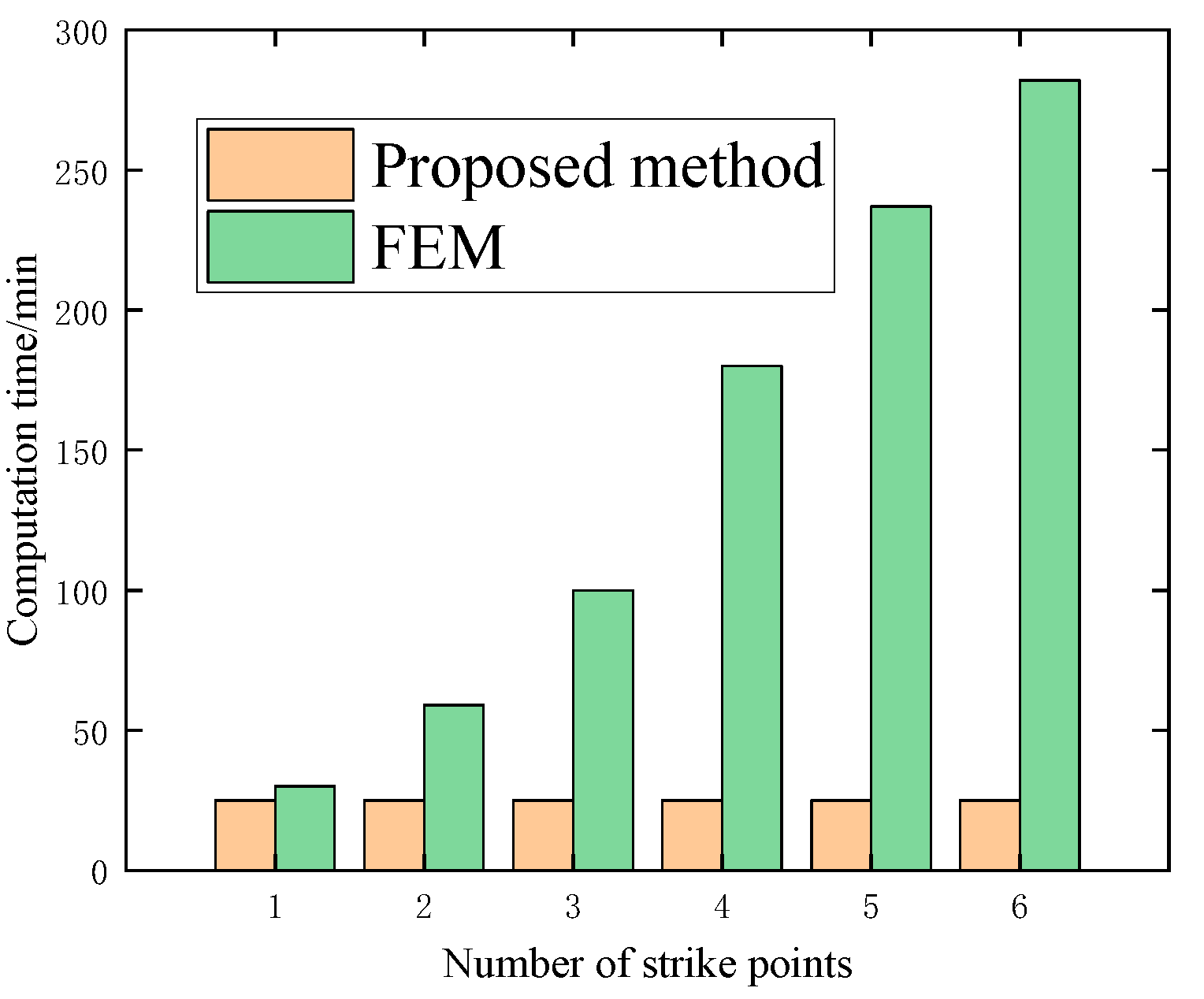
In addition, the proposed method can realize the damage analysis of multi-projectile strikes simultaneously, and the calculation time is the same with an increase in the number of strikes as shown in
Figure 9. In contrast, the computational time of FEM shows a linear increase with an increased number of strikes. In the case of six different strikes, the time consumed by the proposed method is reduced by 92.1% compared with the FEM. Therefore, the proposed established method is more efficient than the FEM.
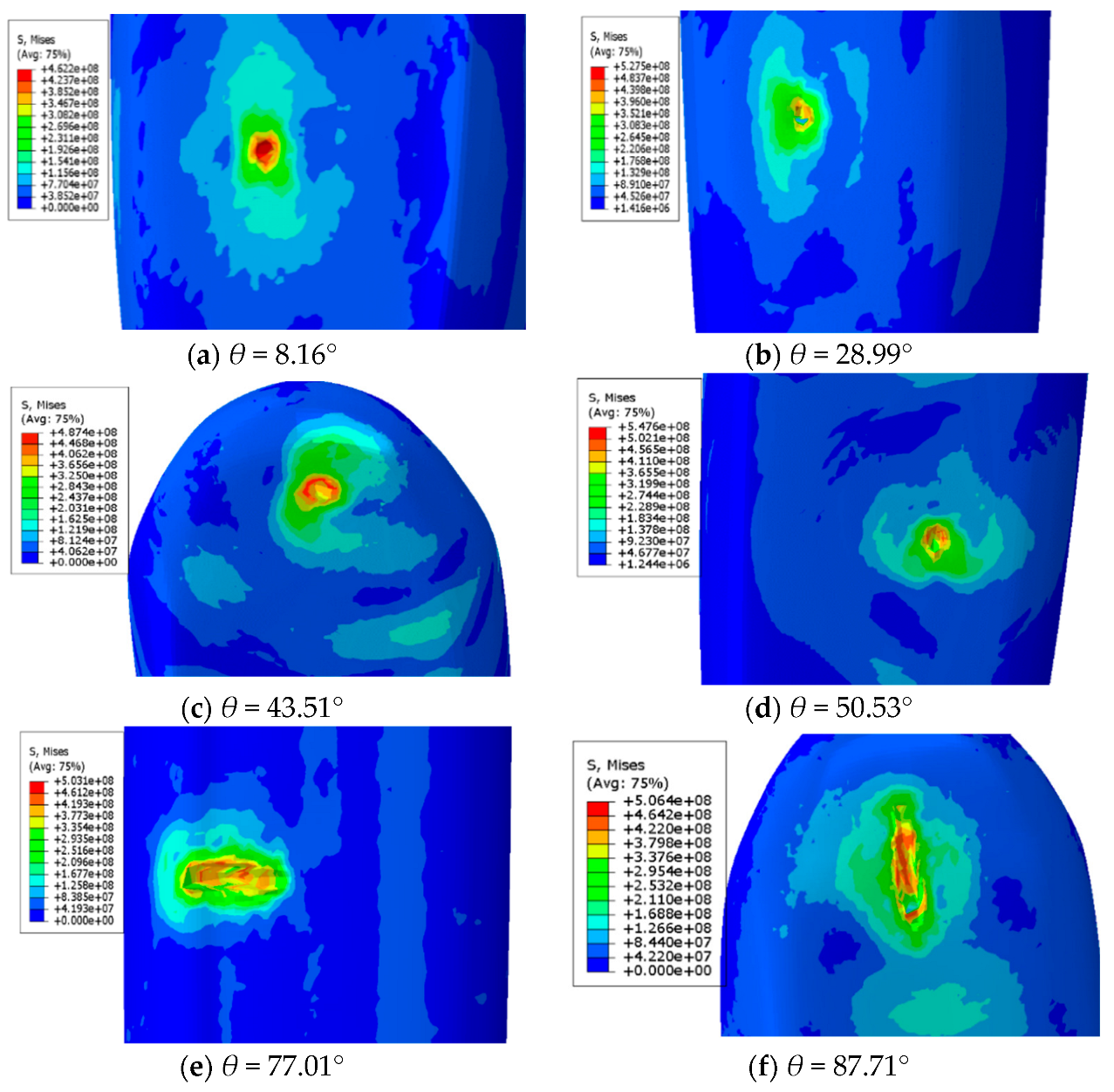
Figure 10 shows the stress nephogram for six impact points. The maximum stresses at the incidence angles of 8.16°, 28.99°, 43.51°, 50.53°, 77.01°, and 87.71° for the six strike points are 462.2, 527.5, 487.4, 547.6, 503.1 Mpa, and 506.4 MPa, respectively. In addition, the damage area increases with an increase in the incidence angle. When the incidence angle reaches 77.01°, the angle between the projectile body and the fuselage surface decreases slightly, leading to ricochet. The projectile body slips and rubs on the fuselage surface, producing a larger damage area. Therefore, when the angle of incidence at the point of impact is large, the slip–friction damage produced by the projectile will cause the structural strength of the fuselage surface to be reduced more, and the degree of danger is high.
Figure 11 shows the maximum stress and residual velocity at different angles.
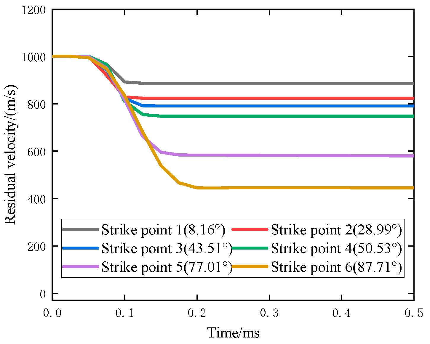
Figure 12 shows the residual velocity with time. The residual velocity of the projectile after striking the helicopter fuselage decreases with the increase in incidence angle at the strike point. With an increase in the incidence angle, the time for the residual velocity leveling off also increases, and the rate of decrease in residual velocity increases when the incidence angle is from 50.53° to 77.01°, while the rate of decrease in the residual velocity is the same when the incidence angle is 77.01° and 87.71°.
Figure 12 indicates that when the incidence angle is larger, the projectile cannot wholly penetrate the fuselage but slips and rubs on the surface of the fuselage, and the contact area between the projectile and the surface of the fuselage increases, which increases the resistance and leads to a faster decrease in the residual velocity. In addition, the residual velocities for the incidence angles of 8.16°, 28.99°, 43.51°, 50.53°, 77.01°, and 87.71° are 886.4, 823.6, 790.8, 747.7, 580.3, and 445.1 m/s, respectively. When the incidence angle is slight, the velocity tends to be stable after the projectile can penetrate the helicopter fuselage. When the incidence angle is too large, the projectile surface and the fuselage surface are in the form of extrusion slip rubbing and cannot wholly penetrate the fuselage, so the phenomenon of ricochet is produced. At this time, the projectile also tends to speed up after slip rubbing.
When the angle of incidence is slight, the projectile completely penetrates the surface of the fuselage to form a hole with a small aperture and a minor damage area. This condition is within the repairable range of the helicopter fuselage structure. When the angle of incidence increases to the extent that it is impossible to penetrate the fuselage surface, the projectile slips and scrapes on the surface, and the damage becomes groove-like. The damaged area is prominent, and the repairability decreases.

