Abstract
This work proposes a new effective method to realize variable thrust through discontinuous embedded metal wires in the solid rocket motor (SRM). We aimed to study the influence of discontinuous embedded metal wires on the performance of an SRM with a single-burning-rate grain. A model based on convection heat transfer, heat conduction, and heat radiation was established to calculate the heat transfer in the discontinuous embedded metal wires in the grain, to then obtain the burning rate ratio. Most importantly, a solid rocket motor was designed to verify the feasibility of variable thrust and of the present model prediction, with the embedded silver–nickel alloy wire divided into two segments in the grain. According to the SRM ignition experiment, the silver–nickel alloy wires raised the burning rate of the grain. The pressure varied regularly with changes in the discontinuous embedded metal wires. The theoretical burning rate ratio matched the experimental result well. Based on the verified model, the effects of the burning rate, pressure exponent, burning rate ratio, and number of wires on thrust were investigated. Burning rate, burning rate ratio, and pressure exponent were found to be positively correlated with thrust ratio. The thrust ratio could reach 12.5 when the burning rate ratio was 5. The ability to adjust thrust tended to increase with an increase in the number of wires. This study also provided a method to assess whether the consecutive embedded metal wires had been broken or not. The method using discontinuous embedded metal wires in the grain was proven to be feasible to realize multi-thrusts of single-burning-rate grain, which is a new idea for the design of a multi-thrust SRM.
1. Introduction
A solid rocket motor (SRM) needs diverse thrusts at different times, according to the aircraft flight required. Moreover, double thrusts and multiple thrusts of a single chamber are frequently used. Generally, two methods are applied to meet the requirements. One method is applying two or three propellants in series with different burning rates or adjusted grain structures. The other one is applying embedded metal wires in grains [1,2]. When metal wires are embedded in the grain, the temperature of the grains close to the metal wire rises relatively faster, and the section of grain close to the metal wire is ignited when the ignition temperature of the grain is reached, and the burning surface changes simultaneously.
There have been many research achievements regarding single-chamber solid rocket motors with double thrusts or multi-thrusts. It is a mature computational method of internal ballistics to adjust the structure of single-burning-rate grains. It can deal with complicated structural changes such as intersection, separation, and the vanishing of burning surfaces [3,4,5] and calculate the transient burning rate of grains for a solid rocket motor [6,7,8,9,10]. While the initial interface shapes of the two kinds of propellants are unpredictable, the burning surfaces of the two kinds of propellant interface shape change rapidly [11,12,13]. As a result, it is difficult to accurately calculate the diversification of thrust or pressure while two kinds of propellants are burning at the same time. Meanwhile, many studies have focused on the influence of embedded metal wires on the burning rate. Their research methods have consisted of the following: calculating the change in burning rate or burning surface with the change in the metal wires [14,15]; estimating the function via internal ballistics [16,17]. Usually, the metal wires are made of silver or an alloy. Due to the fact that the burning rate ratio of specific metal wires is relatively fixed for specific propellants, we can achieve accurate calculations of thrusts via these metal wires.
The distribution of metal wires in grains has a positive effect on the performance of solid rocket motors, especially in the initial stage and descending stage. It can shorten the time from ignition to a state of balanced pressure if the distribution of the metal wires is reasonable. The material properties of metal wires, such as thermal diffusivity, melting temperature, diameter, and blackness, can affect the acceleration effect of the burning rate [18]. When the grain contains metal wires of the same material and with the same diameter, the change in burning rate is more sensitive if the grain has a lower burning rate and lower ignition temperature. Moreover, there is a better burning rate-increasing effect in lower-burning-rate grain; on the contrary, the burning rate-increasing effect in higher-burning-rate grain is poor. There exists an optimal wire diameter that allows for the maximum burning rate for specific propellants [17,19,20].
A simple method involves applying single-burning-rate grain with discontinuous embedded metal wires (GNEMWs) to realize multi-thrusts in a solid rocket motor. However, relevant research on this method has not been reported by any public study. A heat transfer analysis of GNEMWs has not been conducted, and an experiment assessing a discontinuous embedded wire column has not been reported either. In addition, the effect of discontinuous embedded wires on the thrust ratio and the burning rate ratio is unknown; as these are two important operation parameters for an SRM, it is necessary to conduct theoretical and experimental research to resolve this issue.
To verify the feasibility of tuning the ballistic performance of a single-burning-rate grain SRM via new discontinuous embedded metal wires, a one-dimensional heat transfer equation of metal wire and two-dimensional equations of grain were established to obtain the burning rate ratio of the grain with embedded discontinuous metal wires and calculate the internal ballistic performance of the SRM. Ignition experiments on grain embedded with discontinuous embedded metal wires were also carried out at the same time. We also conducted a comparison between the simulation data and experimental data. Using the aforementioned validated methods, a wire break simulation calculation of the grain with continuous embedded metal wire was conducted. Lastly, the effects of different types of propellants and various kinds and quantities of metal wires on thrust were also investigated.
2. Numerical Model
2.1. Basic Hypothesis
This study focused on the study of burning rate change in grain with a change in the discontinuous embedded silver–nickel alloy metal wires. In order to simplify the calculation process, some unimportant factors were ignored. The specific parameters of the experiment are as follows:
- (1)
- The heat transfer mode between silver–nickel alloy metal wires and the combustion gas of the propellant is heat convection and radiation; the heat transfer mode between silver–nickel alloy metal wires and grains is heat conduction; the heat transfer mode between combustion gas and grains is heat convection and radiation.
- (2)
- The burning of grains which are far away from the silver–nickel alloy metal wires abides by the parallel burning law. The grain close to silver–nickel alloy metal wires is ignited when the grain temperature rises to ignition temperature and the burning rate of the grains close to the metal wires differs depending on the position.
- (3)
- The silver–nickel alloy metal wires break when the temperature rises to the melting temperature. These broken silver–nickel alloy metal wires are useless for grains and combustion gas, and there is no heat convection or heat radiation between each other.
- (4)
- When the diameter of silver–nickel alloy metal wires is relatively smaller, namely less than one millimeter, the temperature diversity in the radial direction is ignored and the temperature gradient only exists in the axial direction.
- (5)
- Combustion gas is uniform everywhere. The flow of combustion gas has no influence on the heat convection among gas and silver–nickel alloy metal wires and grains.
2.2. Governing Equations
- (1)
- Governing equation for pressure
Due to the fact that the time from igniting to pressure balance in the combustion chamber is very short, usually dozens of milliseconds, its influence is relatively smaller, compared to the whole operation process of the solid rocket motor. Therefore, the zero-dimensional internal ballistics calculation method of the solid rocket motor was adopted. According to the law of conservation of mass and energy, the control equation for pressure was defined by Equation (1) [21]. The density of combustion gas is far less than that of propellant, and the equation could be simplified as in Equation (2) [21].
- (2)
- Heat transfer equations
According to the hypotheses in Section 2.1, there are three main steps in heat convection when the grain is burning with embedded metal wires. The heat transfer mode between metal wires and grains and the heat transfer mode between metal wires and combustion gas of the propellant could be simplified to one-dimensional modes. The heat transfer mode between the combustion gas and the grain could be simplified to two-dimensional modes. The small cells along the axial direction of the metal wires were set as dx, and those along the perpendicular direction were set as dy. The influence of the metal wires embedded in the grains on the burning rate is shown in Figure 1.

Figure 1.
Influence of the embedded metal wire on the burning rate of the grain.
Due to the fact that the heat conduction coefficient of metal wires is greater than that of grains, the temperature of the metal wires along the axial direction changed very quickly, and the section of the grain close to the metal wires was ignited earlier. A taper angle gradually took shape in the grain, and the burning surface increased rapidly at the initial stage. The grain’s burning stabilized when the taper angle was widened to the border of the grain. If the metal wire burned through the grain, the taper angle ensured that the remaining grain abided by the parallel burning law.
For the heat convection mode between the metal wire and combustion gas, the heat transfer equations were defined by Equations (3)–(6). In Equation (4), the incoming heat is divided into two parts; one is the axial heat transfer along the metal wire and the other is the lateral heat transfer. Moreover, is the heat flux and is the cross-section perimeter of the metal wire, and, while also contains two parts, one part is convective heat transfer, and the other part is radiation heat transfer. In Equation (5), due to the high combustion gas temperature, the absorbed heat of the metal wire from combustion gas transfers along the axial direction of the metal wire, and the mode of heat exchange is heat conduction.
The heat transfer between the exposed head of the metal wire and the combustion gas is defined by Equation (7). When the actual temperature of the metal wire reaches melting temperature, the metal wire should melt until it is broken. The temperature of the exposed head of the metal wire was considered the melting temperature. This was defined by Equation (8). The process included heat convection and heat radiation, but no heat conduction.
At the same time, the heat change in the metal wire per unit volume could also be defined by Equation (9), as follows:
According to the energy conservation law, the aforementioned Equations (3)–(5) and (9) could be merged into the following Equations (10)–(12), as follows:
For the heat convection mode between the metal wire and the grain, the heat transfer was defined as Equations (13)–(16). The heat transfer of the metal wire changed from the entry to the exit. Due to the fact that the metal wire and grain were close to each other, there was no radiation. It was assumed that all the components of the grain were symmetrical and that the heat conduction coefficient of the grain was a fixed value. At the same time, the heat change in the metal wire per unit volume could also be defined by Equation (17). In Equation (14), the incoming heat is divided into two parts; one is the axial heat transfer along the metal wire and the other is the lateral heat transfer. Moreover, is the heat flux and is the cross-section perimeter of the metal wire.
Similarly, the aforementioned Equations (13)–(16) could be merged into the following Equations (18)–(20) [21], according to the energy conservation law, as follows:
For the heat convection between the combustion gas and the grain, the heat transfer processes are very complicated. In order to simplify the process, it was assumed that the temperature of the grain’s burning surface was the ignition temperature, which is defined by Equation (21). Usually, the ignition temperature is 650 K.
In order to obtain the heat transfer density between the metal wire and the grain, it is necessary to study the temperature distribution inside the grain. A small unit volume of grain was taken. By combining the basic heat convection equations and geometry parameters, it could be defined by Equations (22) and (23). Equation (23) is the supplementary boundary condition between the grain and the combustion gas heat exchange surface [18]. There is only thermal conduction within the grain, and the grain is assumed to be a two-dimensional model, in which the change in temperature of the propellant column is related to the heat absorbed and released.
Equations (8), (21), and (23) are all applied as boundary conditions. An adiabatic boundary condition is set between the propellant column and the rubber layer. At the beginning of the computation, the surface temperature of the propellant column is set to the ignition temperature.
- (3)
- Burning rate ratio
The heat conduction coefficient of silver–nickel alloy metal wires is larger than that of the grain. The heat is transferred from the silver–nickel alloy metal wire to the grain, while the silver–nickel alloy metal wire is heated by combustion gas. This raises the temperature in the grain, which is close to the metal wire. When the temperature of the grain reaches the ignition temperature, the grain is ignited. The burning rate of the grain close to the metal wire increases faster, compared to the basic burning rate, which is obtained through experimental testing. Therefore, the burning rate ratio can be defined by Equation (24) [21]. When the burning of the grain stabilizes, Equation (24) could be defined by Equation (25) [21], as shown in Figure 1.
3. Experimental Methods
The grain model with discontinuous embedded silver–nickel alloy metal wires is defined in Figure 2a. The metal wire had two segments along the axial direction, each of which related to a small nylon wire. It was assumed that the small nylon wire had no effect on the grain. The two metal wires connected with the small nylon wire were fixed in the cladding layer by instruments before casting grain slurry. The cladding layer of grain was made from insulation material, which had the functions of heat insulation and ablation resistance. The length of the head segment metal wire was 70 mm, that of the tail segment metal wire was 65 mm, and the length of the nylon wire was 75 mm.
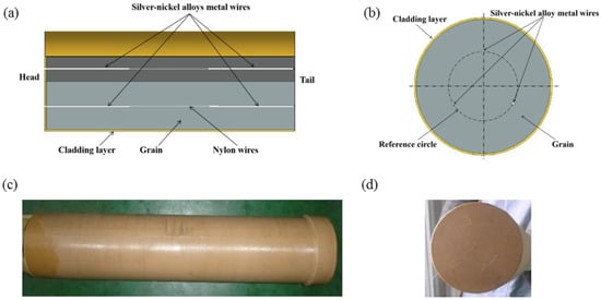
Figure 2.
(a) Cross-section along the axial direction of the grain model with discontinuous embedded silver–nickel alloy metal wires; (b) cross-section along the radial direction of the grain model with discontinuous embedded silver–nickel alloy metal wires; (c) profile of the physical grain; (d) head of the physical grain.
The solid propellants were prepared. The propellant components were kept at a fixed formula (Al: 17 wt.% ammonium perchlorates (AP): 70% wt.%) with a particle diameter of 60–80 μm, 11% hydroxyl-terminated Polybutadiene (HTPB) as the binder, and 2% Isophorone diisocyanate (IPDI) and dioctyl sebacate (DOS)as the plasticizer. The silver–nickel alloy, the intensity of which is 450 MPa, has much better manufacturability than pure silver, whose intensity is 150 MPa. This can reduce the breakage risk of silver–nickel alloy metal wires during the process of fixing metal wires, grain shrinking, and grain solidifying. The grain had three silver–nickel alloy metal wires, as shown in Figure 2b. As shown in Figure 2c, there was a yellow rubber cover around the real grain. The head diameter of the grain was slightly larger, and there was a little step for locating it. There were three wires sticking out through the rubber material. The wire could be clearly seen and they were completely embedded into the grain, as shown in Figure 2d.
To verify the feasibility of the grain with discontinuous embedded silver–nickel alloy metal wires, an ignition experiment of the solid rocket motor was designed. The materials of the solid rocket motor are shown in Table 1.

Table 1.
Materials of the solid rocket motor.
The solid rocket motor was heated at 20 °C for 12 h in the heating box before the ignition experiment. The grain was of free-loading type and was loaded from the head of case. During the motor test, the pressures of two channels were tested and installed at the rear side of the SRM. The range of the pressure sensor was 0–25 MPa, the sampling frequency was 5 kHZ, and the test uncertainty was 0.05% FS. The measurement range of the thrust sensor was 0–5 kN, the sampling frequency was 5 kHZ, and the test uncertainty was 0.1% FS.
4. Results and Discussion
4.1. Solid Rocket Motor Firing Verification of Discontinuous Embedded Metal Wires (GNEMWs)
Essential heat transfer processes were computed, and the computation range was a cylinder whose diameter was twenty times that of the metal wire, with cell sizes measuring 0.1 mm by 0.1 mm, totaling approximately 180,000 cells, and a temporal resolution of 0.01 s. The program monitored the length of the propellant ignition within a unit of time and compared it to the intrinsic burning rate of the propellant to obtain the current burning rate ratio.
The calculated burning rate ratios were translated into angles within a three-dimensional model, and the regression of the burning surface was achieved using the secondary development software Pro/Engineer(PRO/E). At a specific moment in time, the burning rate for different positions was averaged. After obtaining the burning surface–web thickness curve, the pressure and thrust curves of the engine were calculated according to the internal ballistics equation of the SRM. The calculation parameters of the grain are shown in Table 2.

Table 2.
Simulation parameters of heat transfer.
In Figure 3a, it can be seen that the burning rate ratio’s peak value was in the ignite initial stage and descended generally from 3.5 to 2.2 until the head segment of the silver–nickel alloy metal wire was burnt out. The second segment of the silver–nickel alloy metal wire also exhibited its peak burning rate ratio value when the metal wire head was exposed, and then the burning rate ratio descended generally from 2.8 to 2. Compared to references [12,14,16], the growth rate of the silver–nickel alloy was relatively low, which is due to the lower thermal conductivity of nickel, while the variation pattern of the burning rate ratio of silver-nickel alloy wires within the grain is similar to that of other metal wires, which revealed a temporal evolution characterized by an initial increase, subsequent decrease, and eventual stabilization.
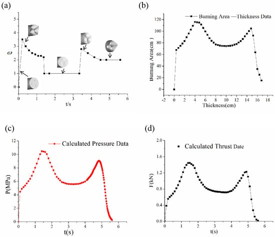
Figure 3.
(a) Change in burning rate ratio with the varying operation time of the solid rocket motor. (b) Curve of calculated burning surface to thickness; (c) calculated pressure curve; (d) calculated thrust curve.
The change in the burning surface of the grain can be summarized in six stages. In the first stage, the initial burning surface is the end-face, and the burning surface is small with the taper angle by the silver–nickel alloy metal wires being negligible. In the second stage, the silver–nickel alloy metal wires play a significant role, and the burning surface gradually increases until it reaches its peak value. During the third stage, the head segment of the silver–nickel alloy metal wires is burnt out, leading to a general descent in the burning surface. Moving to the fourth stage, the taper angle almost disappears, and the burning surface becomes close to a plane. In the fifth stage, the second segment of the silver–nickel alloy metal wires appears, forming a taper angle once again. In the final stage, the grain is burned through by the second segments of the silver–nickel alloy metal wires.
Eventually, the burning surface curve with the thickness variation was established. The curve of the burning surface is shown in Figure 3b, which shows expected pattern changes, namely first increasing, then decreasing, followed by an increase and a subsequent decrease. According to the internal ballistics Equations (1) and (26), the pressure curve with time of which is shown in Figure 3c, the thrust curve with time is shown in Figure 3d.
According to the experimental methods outlined in Section 2, ignition tests were carried out on segments embedded with metal wires of the grain. The dimensions and properties of the propellant grains are presented in Table 1. As shown in Figure 4a, the pressure exhibited a double-peak pattern of increasing first and then decreasing, mirroring the simulation expectations, indicating the plausibility of the simulation results. An analysis of the flame size of the engine during the experimental process was conducted. From the pictures, it can be observed that, at higher pressures, the flame was larger, and the Mach waves within the flame were clearly visible. Conversely, at lower pressures, the flame was smaller, and the Mach waves were not as distinct.
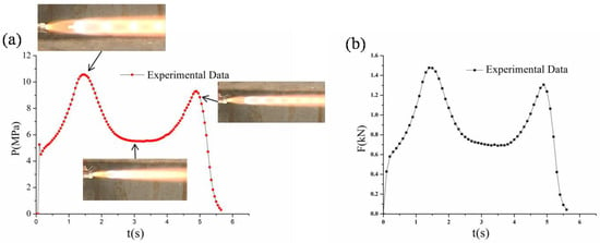
Figure 4.
(a) Pressure curve of the grain with discontinuous embedded silver–nickel alloy metal wires; (b) thrust curve of the grain with discontinuous embedded silver–nickel alloy metal wires.
As shown in Figure 5a, the test pressure curve was smooth, and the experimental curve corresponded to the calculated pressure curve. We defined the section between the first and second pressure peaks as the stable working phase, with a maximum pressure ratio of 1.89. Increasing the length of the metal wire extended the duration of the peak pressure. The experimental results indicated that grains embedded with two segments of metal wires could achieve three levels of pressure adjustment. In Figure 5b, the trend of the thrust curve resembles the pressure curve. Referring to the definition of the stable working phase, the maximum thrust ratio was 1.93. This research provides a viable option for adjusting thrust levels according to aircraft requirements.
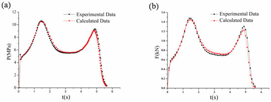
Figure 5.
(a) Pressure curve comparison between the experiment and the calculation of the grain with discontinuous embedded silver–nickel alloy metal wires; (b) thrust curve comparison between the experiment and the calculation of the grain with discontinuous embedded silver–nickel alloy metal wires.
The internal ballistic curve of the solid propellant column with continuously embedded metal wires should be rather stable and the experimental curve should be similar to the normal calculated data. However, sometimes there was an unexpected decrease followed by an upward change during actual SRM testing, as shown in Figure 6a. Within the range from 1 s to 2 s, there was a maximum pressure drop of 1.2 MPa, and the operation time increased by 0.3 s. This trend was very similar to the pressure and thrust curves of the segmented embedded metal wires’ grain, wherein the thrust initially dropped and then returned to normal. Therefore, through continuous attempts to identify the starting point of the break and the length of the broken metal wire, after many trials, it was found that the calculated curve closely matched the abnormal curve obtained from the experiment when the break length was set to 5.2 mm and the starting point was 21.6 mm away from the head. In Figure 6b, the thrust also exhibited a noticeable decrease, with the maximum drop being 2.3 kN. These findings were similar to those found in the master’s thesis of Paul B. Wilson [22], wherein the presence of breakpoints in metal wires led to a trend in the pressure and thrust curves of a first decline followed by an increase.
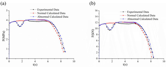
Figure 6.
(a) Typical pressure curve comparison of experiment and calculation for abnormal fluctuations; (b) typical thrust curve comparison of experiment and calculation for abnormal fluctuations.
4.2. Thrust Ratio Prediction in Different Propellants of Discontinuous Embedded Metal Wires (GNEMWs)
The burning rate and pressure exponent varied significantly among different propellants, exerting a considerable impact on thrust. Therefore, this section explores the influence of different burning rates and pressure exponents on thrust under the same-sized propellant grains. Assuming a fixed acceleration ratio of 2.5 for the metal wires, varying the pressure exponent between 0.3 and 0.45, and varying the burning rate between 10 mm/s and 40 mm/s, the relationship between burning rate-to-thrust ratio and pressure exponent-to-thrust ratio could be obtained, based on the internal ballistic calculation formula (Equation (26)). The first point of comparison was taken as the baseline, as illustrated in Figure 6. In Equation (26), the thrust coefficient could be considered a constant value, eliminating it when calculating the thrust ratio. From Figure 7a, it can be observed that, at an acceleration ratio of 2.5 and a propellant burning rate of 29 mm/s (6 MPa, 20 °C), there was a positive correlation between pressure exponent and thrust. In Figure 7b, with an acceleration ratio of 2.5 and a pressure exponent of 0.3, the trend was similar to that seen in Figure 7a.
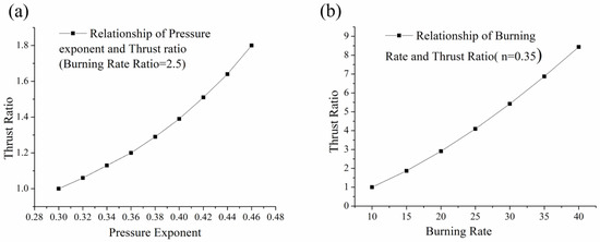
Figure 7.
(a) Relationship of pressure exponent and thrust ratio (burning rate ratio = 2.5); (b) relationship of burning rate and thrust ratio (burning rate ratio = 2.5).
4.3. Thrust Ratio Prediction in Different Metal Wire Materials and Numbers of Discontinuous Embedded Metal Wires (GNEMWs)
There are many materials that can play the same role in increasing the burning rate of grain, such as silver wires, copper wires, and so on. The burning rate ratio could change from 1.0 to 5.0 for different materials. Therefore, we can compute the thrust ratio for end-face burning grain with different embedded metal wires. As shown in Figure 8, the thrust ratio could reach 12.5 when the burning rate ratio was 5, and we could regulate the thrust by choosing different materials for the metal wires. In reference [19], the authors conducted calculations on the impact of thermal properties of different metallic materials on the acceleration ratio. The results showed that the acceleration ratio varied with different diameters, ranging from 1 to 4.2. This is consistent with the acceleration ratio assumption of 1 to 5 in this study.
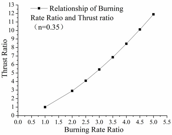
Figure 8.
Relationship of burning rate ratio and thrust ratio (pressure exponent = 0.35).
The number of metal wires had a discernible impact on both pressure and thrust. Thrust calculations were conducted using three, six, and nine silver–nickel alloy wires. As depicted in Figure 9a, the pressure change for the three-wire configuration was the slowest, while the pressure change for the nine-wire configuration was the fastest. With an increasing number of wires, both the ascent and descent of pressure occurred more rapidly, indicating that a higher wire count corresponded to a greater pressure adjustment capability. A comparison of the pressure among three, six, and nine wires revealed significant variation between three wires and six wires, whereas the variation between six wires and nine wires was minimal. This suggests that the pressure-adjusting capacity of wires approached its maximum with an increasing number of wires, and thrust experienced minimal change with additional wires. The thrust curves exhibited a similar trend to the pressure curves, as illustrated in Figure 9b. This calculation result corresponds with the findings in reference [22], which indicated that, the greater the number of metal wires, the faster the pressure and thrust curves rise and fall.
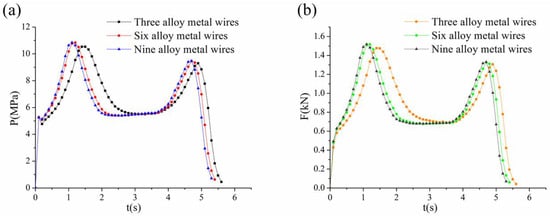
Figure 9.
(a) Indicates pressure data of the grain with three/six/nine discontinuous embedded silver-nickel alloy metal wires; (b) indicates thrust date of the grain with three/six/nine discontinuous embedded silver-nickel alloy metal wires.
5. Conclusions
Due to the unpredictable interface shape of two types of propellants, accurately calculating thrust and pressure diversification becomes challenging. The fluctuation in pressure and thrust poses safety and control risks in aircraft. To address these challenges, theoretical and experimental research is conducted to investigate the influence of discontinuous embedded silver–nickel alloy metal wires on the grain of a solid rocket motor. In this study, a silver–nickel alloy is utilized as the wire material, divided into two segments and embedded in the grain. The findings reveal the following key points:
Pressure and thrust undergo regular changes with the variation in discontinuous embedded silver–nickel alloy metal wires. This regulated change helps mitigate fluctuations in thrust and pressure. The burning rate ratio varies with operation time. Discontinuous embedded metal wires prove to be an effective method for achieving variable thrust in the solid rocket motor.
This study provides insight into explaining abnormal pressure fluctuations when metal wires break in a grain with discontinuous embedded metal wires. The disappearance of metal wires results in a reduction in the burning surface, while the burning surface increases if the embedded metal wires reappear.
By considering the pressure exponent and burning rate of the propellant, as well as the range of burning rate ratio of silver–nickel alloy metal wires and numbers, the thrust ratio of the solid rocket motor can be significantly altered.
Author Contributions
Conceptualization, Q.W.; methodology, Q.W.; formal analysis, Q.R.; data curation, Q.W.; writing—original draft preparation, Q.W.; writing—review and editing, Q.R. All authors have read and agreed to the published version of the manuscript'.
Funding
This research received no external funding.
Data Availability Statement
The raw data supporting the conclusions of this article will be made available by the authors on request.
Conflicts of Interest
The authors declare no conflicts of interest.
Correction Statement
This article has been republished with a minor correction to the existing affiliation information. This change does not affect the scientific content of the article.
Terms and Definition
| : | Burning surface of the grain, m2 |
| : | Nozzle throat area, m2 |
| : | Cross-section area of the metal wire, m2 |
| : | Burning surface of grain without any embedded metal wire, m2 |
| : | Characteristic velocity, m/s |
| : | Specific heat capacity of the metal wire, J/(kg·K) |
| : | Specific heat capacity of the grain, J/(kg·K) |
| : | Thrust coefficient |
| : | Thrust of the solid rocket motor, N |
| : | Heat convection coefficient between combustion gas and the metal wire, W/(m2·K) |
| : | Heat convection coefficient between combustion gas and the grain, W/(m2·K) |
| : | Perimeter of the metal wire, m |
| : | Pressure exponent |
| : | Normal direction of grain burning surface |
| : | Combustion chamber pressure, Pa |
| : | Heat transfer between the metal wire and combustion gas |
| : | Heat transfer from combustion gas to the metal wire |
| Heat transfer from the metal wire to combustion gas | |
| : | Heat transfer between the metal wire and the grain |
| : | Heat transfer from the grain to the metal wire |
| : | Heat transfer from the metal wire to the grain |
| Heat transfer density between combustion gas and the metal wire, W/m2 | |
| : | Heat transfer density between the grain and the metal wire, W/m2 |
| : | Gas constant, J/(mol·K) |
| : | Operation time, s |
| : | Combustion gas temperature, K |
| : | Temperature of the metal wire, K |
| : | The head-exposed temperature of the metal wire, K |
| : | Melting temperature of the metal wire, K |
| : | Ignition temperature of the grain, K |
| : | Burning surface temperature of the grain, K |
| : | Temperature of the grain, K |
| : | Chamber’s free volume, m3 |
| x | Axial direction, m |
| y | Radial direction, m |
| : | Coefficient of burning rate |
| : | Heat diffusion coefficient between combustion gas and the metal wire, W/(m2·K) |
| : | Heat diffusion coefficient between the metal wire and the grain, W/(m2·K) |
| : | Blackening of the metal wire |
| : | Blackening of the grain |
| : | Taper angle of the grain close to the metal wire, ° |
| : | Heat conduction coefficient of the metal wire, W/(m·K) |
| : | Heat conduction coefficient of the grain, W/(m·K) |
| : | Metal wire density, kg/m3 |
| : | Propellant destiny, kg/m3 |
| Combustion gas destiny of propellant, kg/m3 | |
| : | Boltzmann constant, J/K |
| : | Burning rate ratio |
References
- Lee, S.; Oh, J.; Lee, H.; Khil, T.; Kim, M. Study on combustion characteristics of thermoplastic solid propellants embedded with metal wires. J. Korean Soc. Propuls. Eng. 2022, 26, 21–27. [Google Scholar] [CrossRef]
- Liu, J.; Wang, Y.; Li, X.; Cong, J. Using the impulse method to determine high-pressure dynamic burning rate of solid propellants. Aerospace 2023, 10, 818. [Google Scholar] [CrossRef]
- Lee, H.; Oh, J.; Yang, H.; Lee, S.; Khil, T. Burn-back analysis for propellant grains with embedded metal wires. J. Korean Soc. Propuls. Eng. 2022, 26, 12–19. [Google Scholar] [CrossRef]
- Cha, J.; de Oliveira, É.J. Performance comparison of control strategies for a variable-thrust solid-propellant rocket motor. Aerospace 2022, 9, 325. [Google Scholar] [CrossRef]
- Dunn; Stuart, S. 3-D grain design and ballistic analysis using the SPP97 code. In Proceedings of the 33th AIAA/ASME/SAE/ASEE Joint Propulsion Conference & Exhibit, Seattle, WA, USA, 6–9 July 1997. [Google Scholar]
- Greatrix, D.R. Transient burning rate model for solid rocket motor internal ballistic simulations. Int. J. Aerosp. Eng. 2008, 5, 826070. [Google Scholar] [CrossRef]
- Hejl, R.J.; Heister, S.D. Solid rocket motor grain burnback analysis using adaptive grids. J. Propuls. Power 1995, 11, 1006–1011. [Google Scholar] [CrossRef]
- Willcox, M.A.; Brewster, M.Q.; Tang, K.C.; Stewart, D.S. Solid propellant grain design and burnback simulation using a minimum distance function. J. Propuls. Power 2007, 23, 465–475. [Google Scholar] [CrossRef]
- Sun, D.; Li, Y.; Liu, P.; Chen, B.; Fan, W. Numerical investigation on the effect of ammonium perchlorate content and position on the combustion characteristics of an ammonium perchlorate/hydroxyl-terminated polybutadiene propellant. Aerospace 2023, 10, 692. [Google Scholar] [CrossRef]
- Yue, S.; Liu, L.; Liu, H.; Jiang, Y.; Liu, P.; Pang, A.; Zhang, G.; Ao, W. Agglomerate size evolution in solid propellant combustion under high pressure. Aerospace 2023, 10, 515. [Google Scholar] [CrossRef]
- Isert, S.; Lane, C.D.; Gunduz, I.E.; Son, S.F. Tailoring burning rates using reactive wires in composite solid rocket propellants. Proc. Combust. Inst. 2016, 36, 2283–2290. [Google Scholar] [CrossRef]
- King, M.K. Analytical modeling of effects of wires on solid motor ballistics. J. Propuls. Power 1991, 7, 312–321. [Google Scholar] [CrossRef]
- Song, M.; Ye, D. Study of a new kind of multipulse rocket motor. J. Propuls. Power 2001, 17, 380–384. [Google Scholar] [CrossRef]
- Kubota, N.; Ichida, M.; Fujisawa, T. Combustion processes of propellants with embedded metal wires. AIAA J. 1982, 20, 116–121. [Google Scholar] [CrossRef]
- Yoo, J. Burning characteristics of nitramine propellant embedded with metal wires. J. Korean Soc. Propuls. Eng. 2000, 4, 50–58. [Google Scholar]
- Hsing, Y.; Wu, S.; Kuo, J. Burning rate of HTPB composite propellant grains with embedded metal wires. In Proceedings of the 28th AIAA Aerospace Sciences Meeting, Reno, NV, USA, 8–11 January 1990. [Google Scholar]
- Xiong, W.; Liu, Y. Burning surface calculation for grain embedded metal wires based on solid work API. J. Beijing Univ. Aeronaut. Astronaut. 2007, 33, 1400–1403. [Google Scholar]
- Gossant, B.; Godfroy, F.; Robert, P. Theoretical calculus of burning rate ratio in grain with embedded Metal Wires. In Proceedings of the 24th Joint Propulsion Conference, Boston, MA, USA, 11–13 July 1988. [Google Scholar]
- Zhang, Y.; Wang, X.; Yang, J. Numerical study of end-burning solid motor embedded with wire. J. Propuls. Technol. 2008, 28, 4–8. [Google Scholar]
- Wei, R.; Bao, F.; Liu, Y.; Hui, W. Combined acceleration methods for solid rocket motor grain burn back simulation based on the level set method. Int. J. Aerosp. Eng. 2018, 2, 4827810. [Google Scholar]
- Li, W.; Wei, Z. Fundamental of Solid Propellant Rocket Motor; Beijing Institute of Technology Publishing: Beijing, China, 2023. [Google Scholar]
- Paul, B. Tactical Missile Performance for Single and Multi-Wire Embedded Propellant Configurations with Discontinuities; Department of the Air Force, Air University: Montgomery, AL, USA, 2019. [Google Scholar]
Disclaimer/Publisher’s Note: The statements, opinions and data contained in all publications are solely those of the individual author(s) and contributor(s) and not of MDPI and/or the editor(s). MDPI and/or the editor(s) disclaim responsibility for any injury to people or property resulting from any ideas, methods, instructions or products referred to in the content. |
© 2024 by the authors. Licensee MDPI, Basel, Switzerland. This article is an open access article distributed under the terms and conditions of the Creative Commons Attribution (CC BY) license (https://creativecommons.org/licenses/by/4.0/).