Article

Multi-Electric Aero Engine Control and Hardware-in-the-Loop Verification with Starter Generator Coordination

1
College of Energy and Power Engineering, Nanjing University of Aeronautics and Astronautics, Nanjing 210016, China
2
Propulsion and Space Research Center, Technology Innovation Institute, Abu Dhabi P.O. Box 9639, United Arab Emirates
*
Author to whom correspondence should be addressed.
Aerospace 2024, 11(4), 271; https://doi.org/10.3390/aerospace11040271
Submission received: 30 January 2024 / Revised: 21 March 2024 / Accepted: 29 March 2024 / Published: 30 March 2024
(This article belongs to the Special Issue Electric Machines for Electrified Aircraft Propulsion)

Abstract

:
The starter generator, characterized by controllable starting torque and disturbance in generator load torque, poses challenges for the multi-electric aero engine control. The key to addressing this issue lies in multi-electric aero engine control with the collaboration of a starter generator. Firstly, a multi-electric aero engine model is established, comprising a full-state turbofan engine model to enhance low-speed simulation capability and an external characteristic model of a starter generator to improve real-time simulation capability. Subsequently, the control methods for a multi-electric aero engine with starter generator coordination are proposed in three processes, including the starting process, acceleration/deceleration process, and steady-state process. During the starting process, the acceleration is controlled by coordinating the torque of the starter generator and the fuel of the aero engine. During the acceleration/deceleration process, the fuel limit value is adjusted based on the electrical load of the starter generator. During the steady-state process, the fuel is compensated based on the q-axis current of the starting generator in response to load torque disturbance. Finally, hardware-in-the-loop simulation experiments are conducted for the control of a multi-electric aero engine. The results show that the coordination reduces the oscillation of the acceleration during the startup of a multi-electric aero engine, enhancing its ability to resist disturbances from electrical load fluctuations during power generation.

1. Introduction

The electrification transformation in aviation is an unstoppable trend. Whether aircraft or aero engine, multi-electric or all-electric is poised to become possible [1]. The multi-electric engines not only need to supply power for traditional more-electric systems but also for electric propulsion systems, which requires larger power output from the starter generator. The starter generator (SG) is a crucial component of a multi-electric aero engine, which is connected to the shaft of the aero engine, enabling the engine to start independently without the assistance of other starting devices, and providing electrical power after startup.
Currently, the power generation capacity of the SG is evolving from kilowatt to megawatt levels, with an increasing impact on the coupling with aero engine [2,3]. In the civilian sector, NASA proposes a partial turboelectric propulsion aircraft called STARC-ABL, equipped with an electric tail fan for boundary layer ingesting [4]. Two multi-electric turbofan engines are required to provide over 2 MW of power output for the electric tail fan [5]. N3-X, another concept proposed by NASA, is a distributed electric propulsion aircraft with a propulsion system driven by 16 electric fans powered by a multi-electric turboshaft engine. The multi-electric turboshaft engine demands a power generation capacity of nearly 50 MW [6]. In the military sector, the application of onboard electric weapons will require high-power electrical energy, with a maximum demand power reaching up to 4.5 MW [7]. During the starting process of the multi-electric aero engine, controllable torque provides more optimization space for starting process control [8]. Whether it is the starting process or the power generation process, considering the coordination of SG in the multi-electric aero engine control design has become increasingly important.
Some researchers approach control studies by treating the aero engine and SG as independent entities. Liu considers the aero engine to be a rigid rotor unaffected by the electrical load when investigating the power generation control of the SG [9]. This assumption implies an infinite load-carrying capacity for the aero engine, which becomes unacceptable as SG’s power increases. Qiu focuses solely on disturbance control from the perspective of perturbed auxiliary power unit states when studying power generation control for auxiliary power units, neglecting the dynamic characteristics of the generator, which could affect the disturbance control effectiveness of the control algorithm [10]. Simon emphasizes the need to comprehensively consider the dynamic coupling between the electrical system and aero engine in the study of multi-electric aero engine control [1]. He proposes an integrated control design method when researching the hybrid propulsion system of STARC-ABL [11] and verifies the advantages of integrated control design over the original decentralized control design in steady state and transient state simulations [12]. Numerous studies have been conducted on the coordinated control of multi-electric aero engines with a dual SG configuration in recent years. Seok proposes a model predictive control algorithm that considers SG coordination to adapt to sizeable transient thrust changes and electrical load variations [13,14,15]. Richter offers an optimal control method considering SG coupling from the perspective of minimal energy consumption, reducing fuel consumption through energy management [16]. Wei suggests an energy-saving regulation approach for multi-electric turboshaft engines based on power distribution, achieving up to a 12.5% reduction in fuel consumption [17]. NASA’s Glenn Research Center proposes a turbine electrical energy management (TEEM) technology, which applies additional shaft torque or extracts shaft torque using SG mounted on different engine shafts. This achieves the goal of bringing the engine’s transient operating line closer to the steady state operating line, reducing the impact of rotor speed and airflow mismatch during engine transitions caused by rotor inertia, and improving the stability during the acceleration/deceleration process [18]. Enalou proposes a solution named electric power transfer (EPT) for power transmission through SG on shafts in a dual-shaft aero engine. Research indicates that EPT technology significantly improves engine performance regarding compressor surge margin, efficiency, fuel consumption, and acceleration/deceleration stability [19]. Thus, it is evident that control methods considering the coordination of SG contribute to performance enhancements in various aspects of multi-electric aero engines. However, the dual SG configuration mentioned above is still in the conceptual design stage. The single SG configuration, which is relatively mature, also needs to consider the coordination of SG.
A multi-electric aero engine model with an SG model serves as the foundation for conducting cooperative control research. Due to the little impact of the high-frequency dynamics of SG on aero engines, the mainstream modeling approach for multi-electric aero engines involves appropriately simplifying the SG model [20]. A verification platform for cooperative control is also crucial for cooperative control research. NASA established a hardware-in-the-loop simulation platform named NEAT, which allows for hardware-in-the-loop simulation validation of TEEM technology [21,22]. In addition to the muti-electric engine control methods with SG coordination, this paper also carries out some innovative work in the modeling and hardware-in-the-loop simulation of multi-electric aero engines. The innovative aspects of this paper include the following:
  • The full-state modeling method for the aero engine proposed in this paper enhances the simulation capability at low speeds. The external characteristic modeling method for SG proposed in this paper introduces a new perspective on SG model simplification by identification.
  • The control methods with SG coordination proposed in this paper improve the starting performance of multi-electric aero engines and reduce the interference of generator load torque on the acceleration, deceleration, and steady-state processes of multi-electric aero engines.
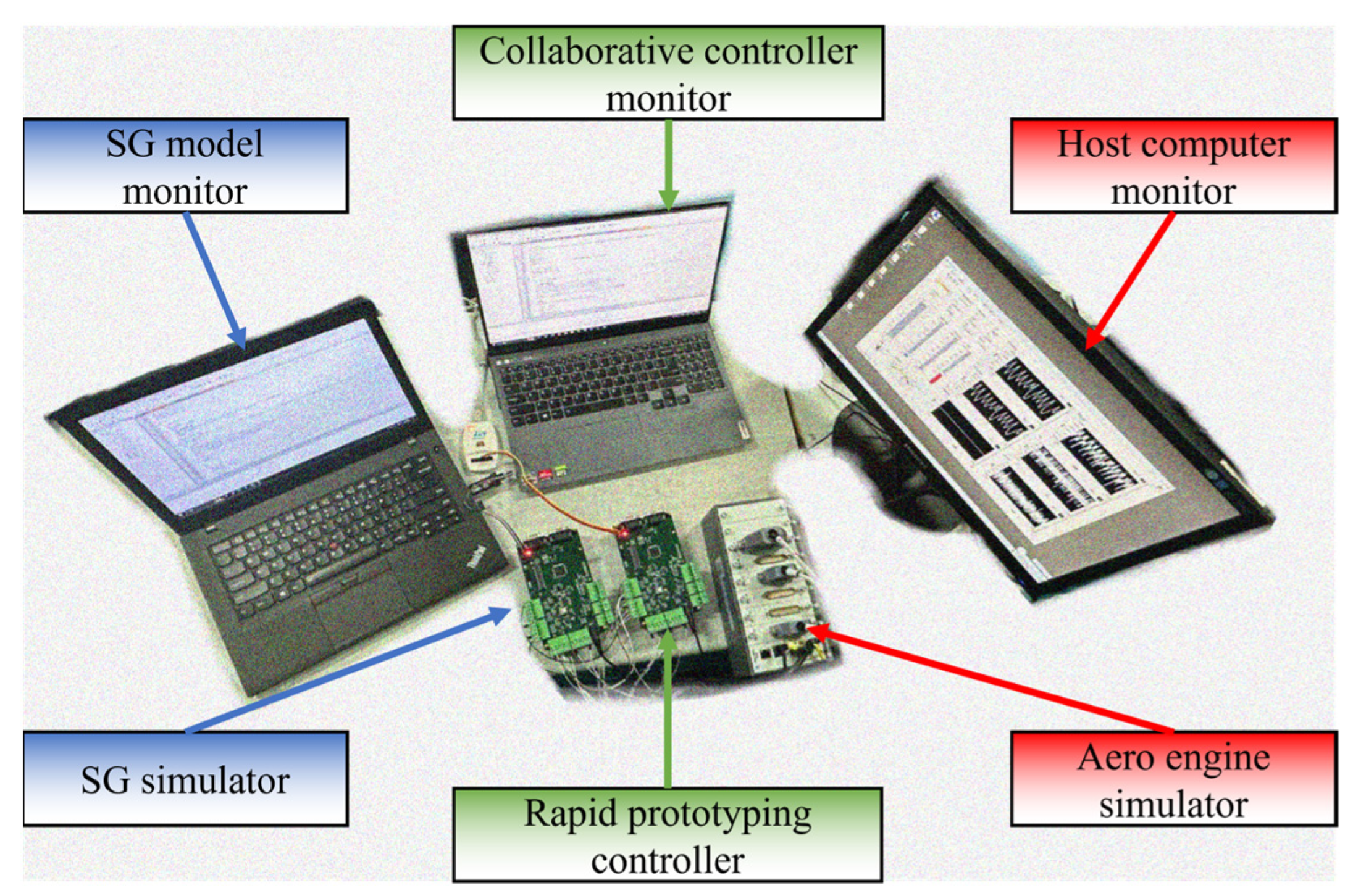
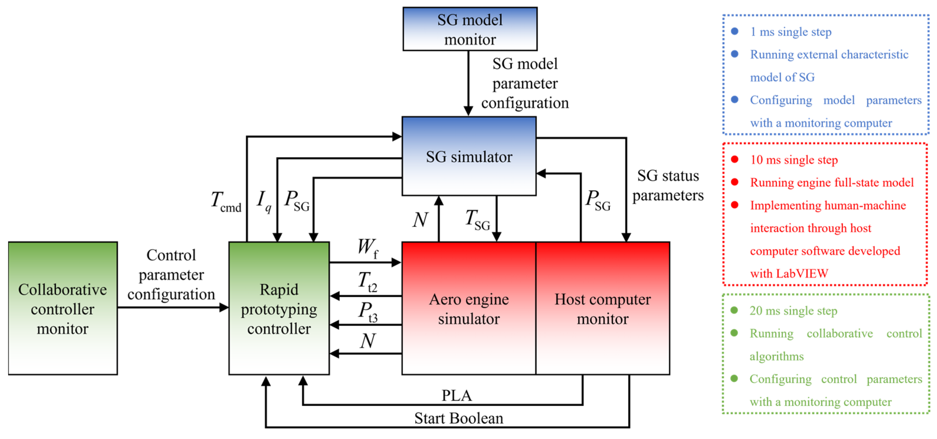
  • The hardware-in-the-loop simulation platform in this paper is designed explicitly for proposed cooperative control methods verification, enabling real-time simulation of a multi-electric aero engine model.
In this paper, the full-state model of the turbofan engine and the external characteristic model of SG for multi-electric aero engine modeling are proposed in Section 2. The control methods for multi-electric aero engines with SG coordination are proposed in Section 3. Section 4 introduces the hardware-in-the-loop simulation platform for cooperative control verification. In Section 5, the results of hardware-in-the-loop simulation in the starting process, acceleration/deceleration process, and steady-state process with electrical load fluctuations are presented and analyzed.

2. Multi-Electric Aero Engine Modeling

The subject studied in this paper is a multi-electric aero engine with an SG connected directly to the high-pressure (HP) shaft. The modeling of a multi-electric aero engine includes both the modeling of the aero engine and the modeling of SG. The modeling methods for the aero engine at above-idle speeds are relatively mature, and this section focuses on modeling the aero engine at low speeds, laying the foundation for the cooperative control study of the starting process. The full-state model can reflect the full-state characteristics of the rotor when the engine is operating at low speeds, including the turbine state, stirrer state, and compressor state. Due to its plodding simulation speed, the electromagnetic model of SG is challenging to apply directly to the model of a multi-electric aero engine. In this section, an SG model including steady characteristics, dynamic characteristics, and nonlinear characteristics is established by identification.

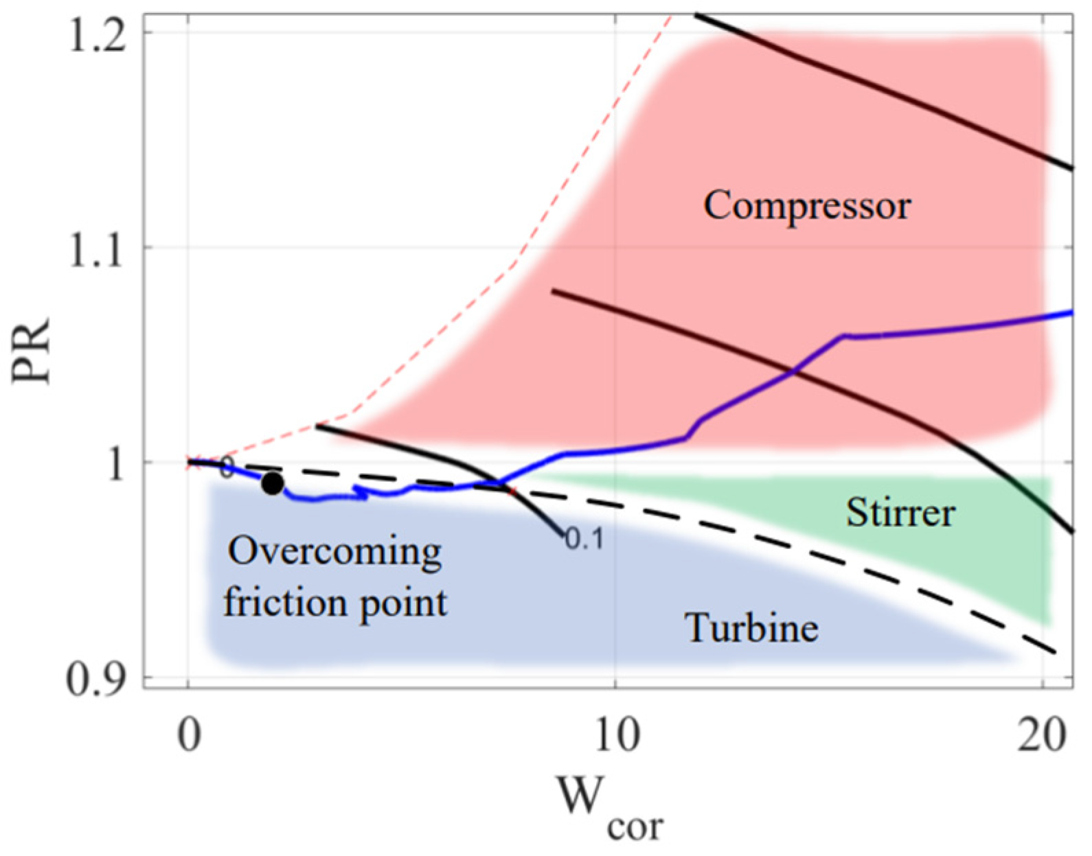
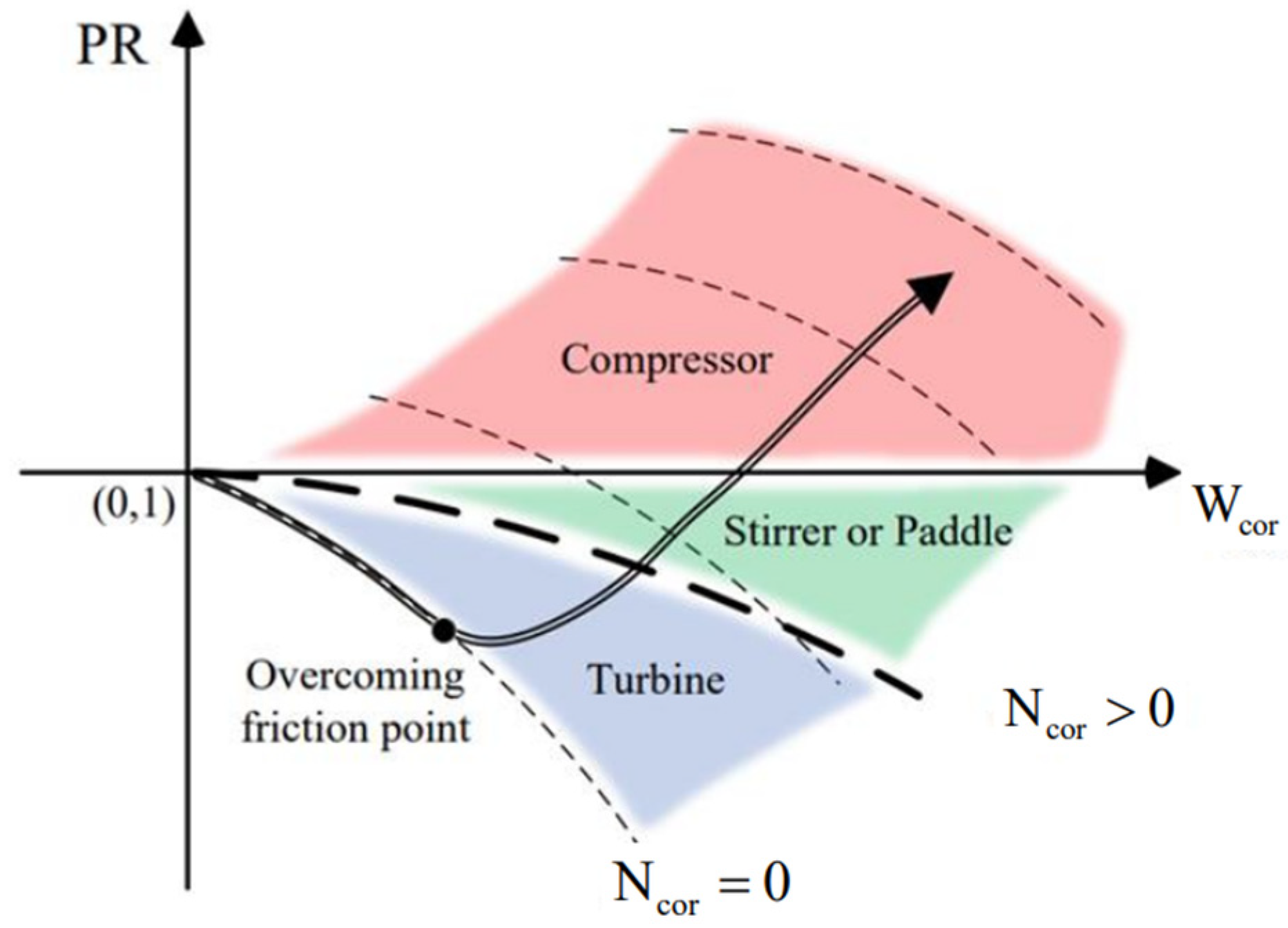
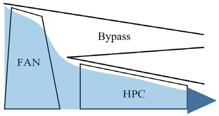
2.1. Full-State Modeling of Turbofan Engine

In the low-speed (including zero-speed) state of aero engines, the rotor operating point deviates significantly from the design point, placing the rotor in an unconventional operating state, which is one of the challenges in aero engine modeling. Currently, the sub-idle model and the above-idle model typically employ two different modeling methods. To ensure model convergence, the sub-idle model prefers the modeling method based on experimental data that does not require iteration.
Some scholars conduct more in-depth research on sub-idle modeling. Bretschneider points out that the engine shutdown state (zero-speed state) modeling, static friction modeling, and variable bypass flow modeling need to be considered in the sub-idle modeling of turbofan engines [23]. As shown in Table 1, Ferrer-Vidal divides the compression component characteristic chart at low-speed speeds into three regions: the turbine region, the stirrer region, and the compressor region [24]. In the initial stage of the starting process for a turbofan engine, the compression component may be in a turbine state.
PR refers to pressure ratio, and W cor refers to converted flow rate. Figure 1 illustrates the starting process of a turbofan engine considering static friction on shafts. In the early stage of the starting process, the starter motor drives the high-pressure (HP) shaft rotor to start, and the low-pressure (LP) shaft cannot overcome the static friction torque, remaining stationary. The fan operating point starts from the initial point with a pressure ratio of 1 and zero flow along the zero-speed line. At this point, the fan is in a turbine state. As the HP shaft speed increases, the airflow increases, and the aerodynamic torque on the LP shaft overcomes the static friction torque, causing it to rotate. At this stage, the fan pressure ratio is still less than 1, and the operating point transitions from the turbine state to the stirrer state. With further acceleration of the LP shaft, the fan’s working capability is enhanced, and the operating point transitions from the stirrer state to a compressor state. The fan operating point transitions from turbine to stirrer state, eventually entering the compressor state for normal operation. The rotor characteristics encompassing turbine state, stirrer state, and compressor state are referred to as the full-state characteristics.
The key to unifying the aero engine modeling methods for sub-idle state and above-idle state lies in obtaining the full-state characteristics of the rotor. The backbone feature method is a parameterized representation of aero engine rotor characteristics developed through collaboration between General Electric and NASA Lewis Research Center in the 1980s [25,26,27]. Shi utilizes the backbone feature method to extrapolate the full-state characteristics of the rotor and establishes a full-state model for a turbojet engine [28]. This section employs the backbone feature method to extrapolate the full-state characteristics of the rotor for turbofan engine modeling.
Static friction on shafts needs to be considered in modeling the shutdown state of an aero engine. During the initial stage of the starting process, the SG drives the HP shaft, while the LP shaft rotor remains stationary for a period because of static friction. Only when the aerodynamic torque overcomes the static friction torque does the LP shaft rotate. Therefore, the rotors dynamics equation considering friction is described as follows:
J H d N H d t = 0   , T HPT T HPC + f static T HPT + T SG T HPC f sliding         , T HPT > T HPC + f static ,
J L d N L d t = 0   ,   T LPT T FAN + f static T LPT T FAN f sliding ,   T LPT > T FAN + f static ,
J H , J L , N H , and N L refer to rotational inertia of the high-pressure shaft, rotational inertia of the low-pressure shaft, high-pressure shaft speed, and low-pressure shaft speed. T FAN , T HPC , T HPT , T LPT , and T SG refer to fan torque, high-pressure compressor torque, high-pressure turbine torque, low-pressure turbine torque, and starter generator torque. f sliding and f static refer to sliding friction torque and static friction torque.
Due to the variable bypass flow state during the initial stage of the starting process, the flow balance equation needs to be modified. When the fan operates at low speeds (including zero-speed) during the initial stage, the suction effect of the core rotor determines the amount of air entering the fan. At this point, it can be approximated that the exit flow from the fan is equal to the inlet flow to the high-pressure compressor, similar to the operating state of a turbojet engine. As the fan speed increases, the fan’s ability to work on the airflow gradually enhances. A portion of the airflow passing through the fan enters the core rotor, while another portion flows through the bypass, entering the normal operating state of a turbofan engine.
As shown in Table 2, the flow balance equation switches between two states based on the fan pressure ratio P R BYPASS . Its fixed value can be calculated by balancing the static pressure at the bypass outlet with the static pressure at the low-pressure turbine outlet, typically falling within the range of 1 to 1.1.
Finally, the full-state model of the turbofan engine is established in MATLAB/Simulink. The speed variation of shafts during the starting process is depicted in Figure 2. In the initial stage, the fan is at zero speed, overcoming static friction torque after around 3 s and initiating acceleration while remaining in the turbine state. Following ignition, the fan speed further increases, its work capability gradually enhances, and it transitions from turbine state to stirrer state. Finally, after approximately 17 s, the fan enters the normal compressor state. The fan operating point trajectory in Figure 3 is consistent with the trajectory analyzed in Figure 1.
The design point parameters for the investigated turbofan engine are presented in Table 3. The parameter design aligns with the requirements of advanced low bypass ratio turbofan engines.

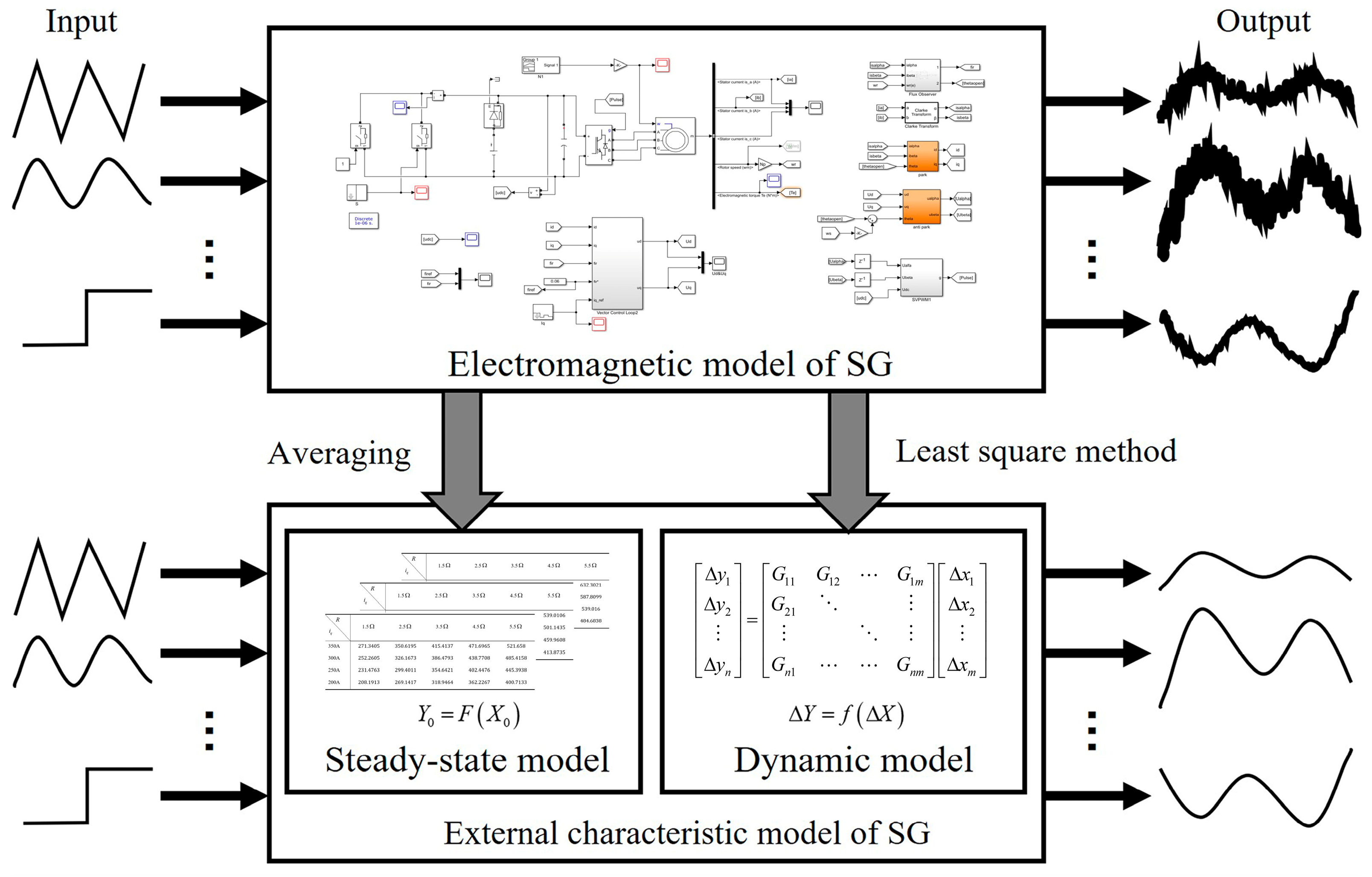
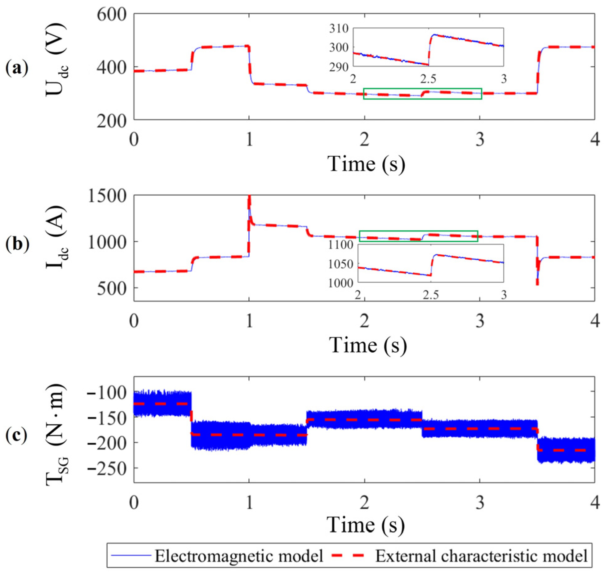
2.2. External Characteristic Modeling of SG

An electromagnetic model established based on voltage equations, magnetic flux equations, and torque equations is often employed in the study of SG control. The electromagnetic model possesses a sufficiently high level of accuracy to achieve a match between simulated data and SG test data [29]. However, the concise simulation step of the electromagnetic model makes it challenging to apply them to hardware-in-the-loop simulation on conventional hardware platforms directly.
The high-frequency dynamics of the electromagnetic model of SG can be neglected for the aero engine because of its large inertia. As shown in Figure 4, the steady-state model of SG can be simplified through averaging. Furthermore, the dynamic model described by the transfer function matrix is identified by the least square method. Although the simplified external characteristic model loses high-frequency dynamics, the simulation speed is significantly improved, making it directly applicable to hardware-in-the-loop simulation for the cooperative control study of multi-electric aero engines.
The following provides a more detailed explanation of the modeling method for the external characteristic model. Without loss of generality, let us assume the external characteristic model has m inputs X = x 1 x m and n outputs Y = y 1 y n . The model can be described as Y = G X , where G is a multivariate nonlinear function. To simplify the identification of the external characteristic model, the model can be further described as follows:
Y = F X 0 + f Δ X ,
F is referred to as the steady-state model, which reflects the steady relationship between the model output and input when the model inputs do not vary with time. f is called the dynamic model, which reflects the dynamic relationship between the change in model output and the change in input when the model inputs vary within a small range over time.
The steady-state modeling involves recording the steady-state mean of electromagnetic model output under different input conditions and establishing n tables of m-dimensional interpolation. The calculation of the steady-state model involves looking up interpolation based on the initial value X 0 and computation of the model output initial values.
A transfer function matrix describes the input–output relationship of the dynamic model.
Δ y 1 Δ y 2 Δ y n = G 11 G 12 G 1 m G 21     G n 1 G n m Δ x 1 Δ x 2 Δ x m ,
Each transfer function is obtained by identifying the electromagnetic model using the least square method. Due to the nonlinearity of the SG model, the transfer function matrix is a matrix that changes with the state of SG. Therefore, a transfer function parameter scheduling strategy is proposed to reflect this variation. Additionally, it can eliminate steady-state errors between the external characteristic model and the electromagnetic model caused by nonlinear factors.
The input vectors Δ X , Δ X j and output vectors Δ Y , Δ Y j are defined as follows.
Δ X = Δ x 1 Δ x 2 Δ x m ,
Δ X j = 0 0 Δ x j 0 0 ,   j = 1 , 2 , , m ,
Δ Y = F X 0 + Δ X F X 0 = Δ y 1 Δ y 2 Δ y n ,
Δ Y j = F X 0 + Δ X j F X 0 = Δ y j 1 Δ y j 2 Δ y j n ,   j = 1 , 2 , , m ,
The static gain K i j i = 1 n ,   j = 1 m of the transfer function G i j i = 1 n ,   j = 1 m is calculated according to the following formula.
K i j = Δ y i Δ x j Δ y i j · g + Δ y i j j = 1 m Δ y i j · g + Δ y i j , Δ y i 0 Δ y i Δ x j Δ y i j · g Δ y i j j = 1 m Δ y i j · g Δ y i j , Δ y i < 0 ,
The sign function is defined as follows.
g + x = x = 1     ,   x > 0 x = 0     ,   x 0 ,
g x = x = 1   ,   x < 0 x = 0   ,   x 0 ,
The advantages of the external characteristic modeling method lie in the following:
  • Compared to the electromagnetic model used in the study of SG control, the external characteristic model of SG allows simulation time steps to be extended to 1 ms. This significantly reduces computational complexity, enhancing the real-time performance of the model.
  • The proposed method is an identification approach for a multi-input, multi-output model of SG. This method is general and applicable for simplifying various SG models.
The main parameters of the identified induction-type SG are shown in Table 4. Under the same input conditions, the comparison of the output parameters during the power generation process between the external characteristic model and the electromagnetic model is shown in Figure 5. Although the external characteristic model neglects the high-frequency dynamics of the electromagnetic model, it fits well with the low-frequency dynamics. In the same simulation environment, a 2 s dynamic process simulation is performed for SG in MATLAB/Simulink. The electromagnetic model takes an actual time of 49.966 s, far from meeting real-time requirements, while the external characteristic model only takes an actual time of 0.564 s.

3. Control Methods with SG Coordination

Due to the coaxial connection of the aero engine with SG, there exists speed and torque coupling [30,31]. Influenced by interdisciplinary factors, most scholars treat the aero engine and SG as independent entities and conduct control research separately. However, as the power of SG increases, the coupling between the aero engine and SG becomes increasingly significant and cannot be ignored.
The coupling between the aero engine and SG is a double-edged sword. During the steady-state operation of a multi-electric aero engine with varying electrical power output, the generator load torque undergoes rapid changes, posing a strong disturbance to the aero engine and affecting its safe operation. When controlling the acceleration of an aero engine, the SG’s rapid torque response enhances the precision of acceleration control, allowing for further optimization of aero engine performance. The cooperative control aims to minimize the impact of coupling disturbances and maximize the advantage of SG’s rapid response. Since SG is connected to an HP shaft, the cooperative control research focuses on controlling the HP shaft speed, denoted as N in the following text.

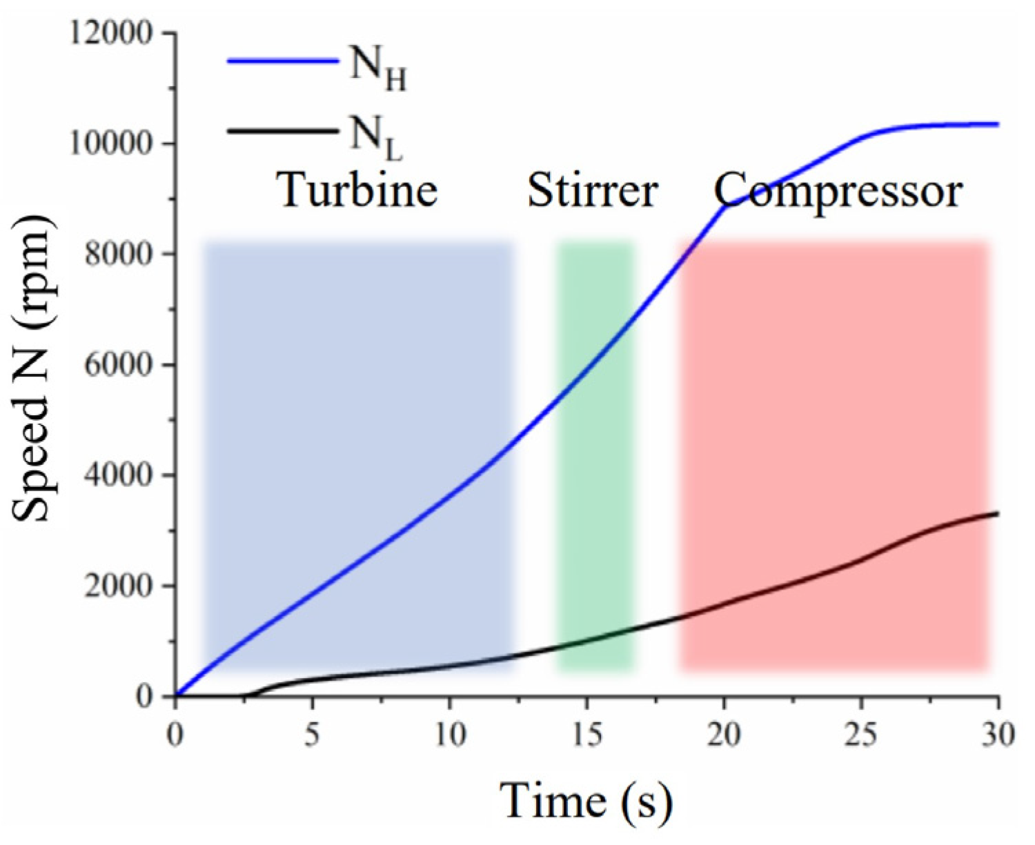
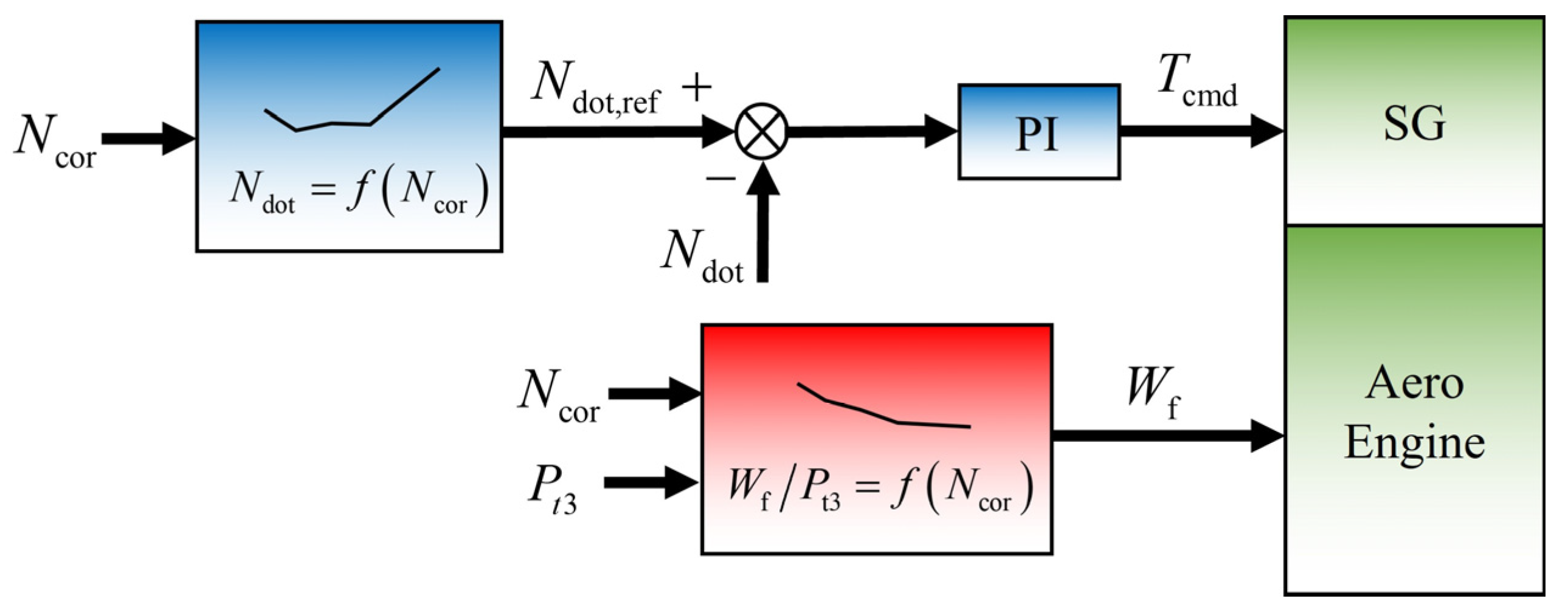
3.1. Cooperative Control Method for Starting Process

In traditional aero engine starting control, the starter motor torque control and engine fuel control are mutually independent. Due to the inability to precisely control the starter motor torque, the starting acceleration of the aero engine is primarily regulated by adjusting the fuel flow. The starting acceleration of the aero engine is constrained by factors such as surge, over-temperature, and flameout. The fuel flow needs to be gradually increased according to the starting control schedule to achieve rapid and stable starting.
The control schedule for aero engine starting includes the fuel-to-air ratio control schedule and the rotational acceleration ( N dot ) control schedule. The fuel-to-air ratio control schedule is widely used in the early years. However, it is difficult to ensure the consistency of engine starting performance due to factors such as performance differences and external atmospheric conditions. The N dot control schedule involves closed-loop control directly on the rotational acceleration of the aircraft engine rotor, ensuring consistent starting acceleration performance. However, when using fuel flow as a controlled variable to control rotational acceleration, oscillations in rotational acceleration may occur, meaning the actual rotational acceleration fluctuates around the commanded rotational acceleration [32,33]. One of the reasons for this issue is the delay in fuel combustion to generate actual torque. The torque response of the starter motor is much faster than the torque response of fuel combustion. If the rotational acceleration is closed-loop controlled by the starter motor torque during the starting process, it will help reduce the oscillation phenomenon in rotational acceleration.
The starting process of the aero engine is divided into three stages, as shown in Figure 6. Stage I involves the starter motor independently driving the rotor acceleration. In Stage II, the starter motor and the turbine cooperatively operate the rotor acceleration. Stage III is characterized by the turbine driving the rotor acceleration. As the rotational speed of the aero engine increases, aerodynamic load resistance also increases, as indicated by the equivalent N dot of load shown by the green line in the graph. The acceleration of aero engine during the starting process requires a collaboration between the starter motor and fuel to provide N dot to overcome the equivalent N dot of load.
The cooperative control between the aero engine and SG is primarily evident in Stage II. Due to factors related to engine performance differences, the N dot provided by fuel combustion is uncertain. Controlling the torque of the starter motor can overcome this uncertainty, ensuring that the starting process accelerates according to the specified N dot schedule.
T cmd refers to torque command, and P t 3 refers to total pressure at the high-pressure compressor outlet section. As depicted in Figure 7, the fuel is provided through an open-loop fuel-to-air ratio schedule in the starting process. The N dot generated by fuel combustion overcomes the primary equivalent N dot of load. The muti-electric aero engine achieves rapid and accurate tracking of the starting N dot schedule through closed-loop control by starter motor torque.

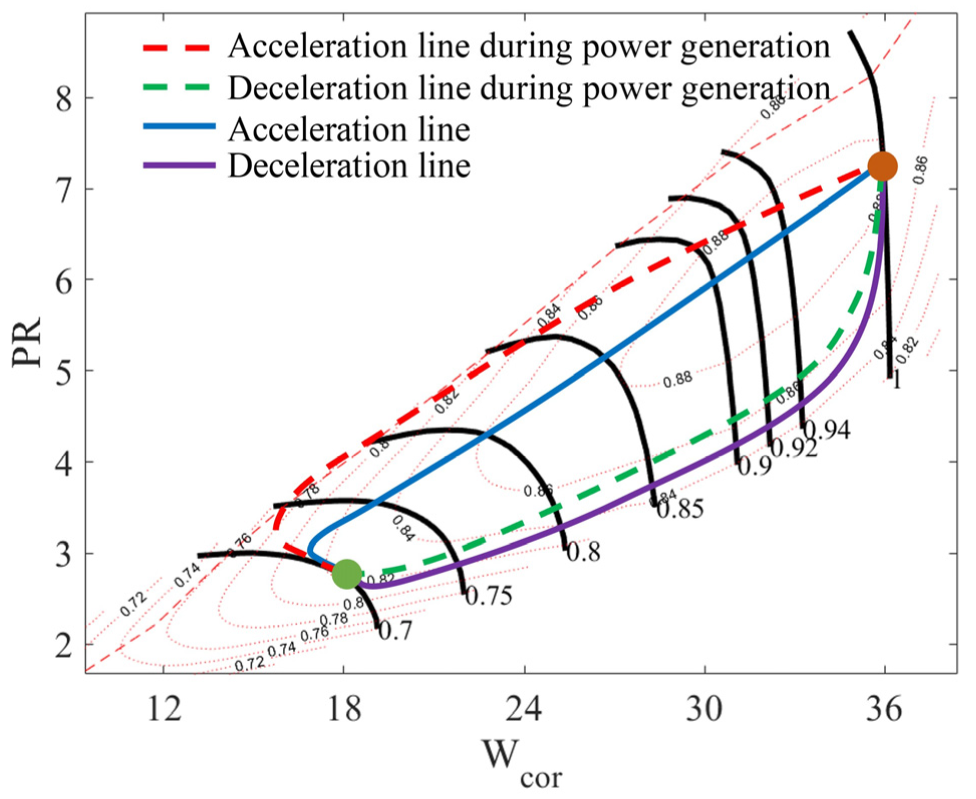
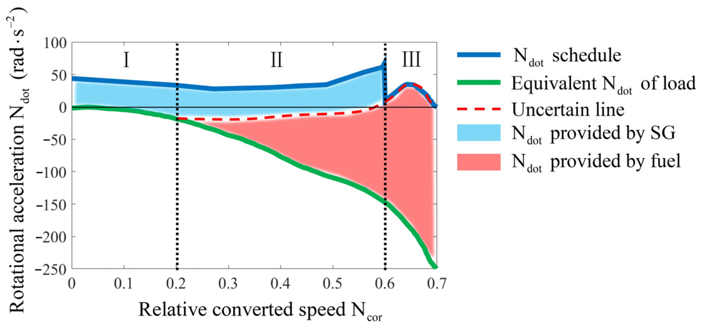
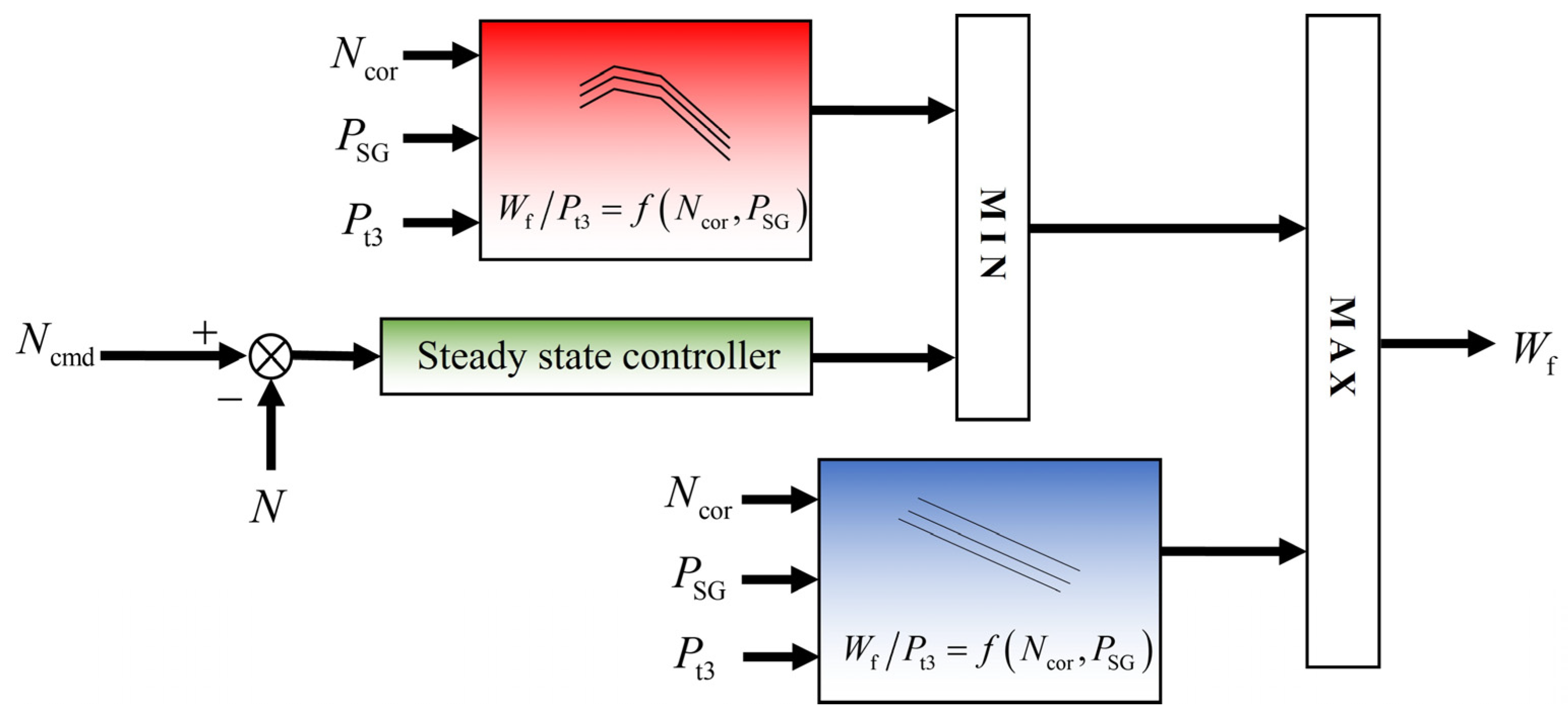
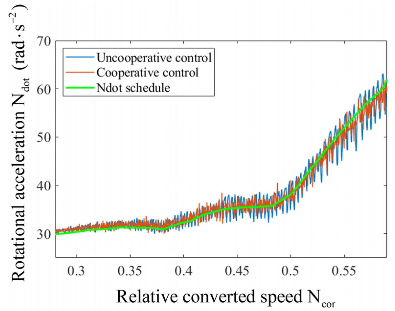
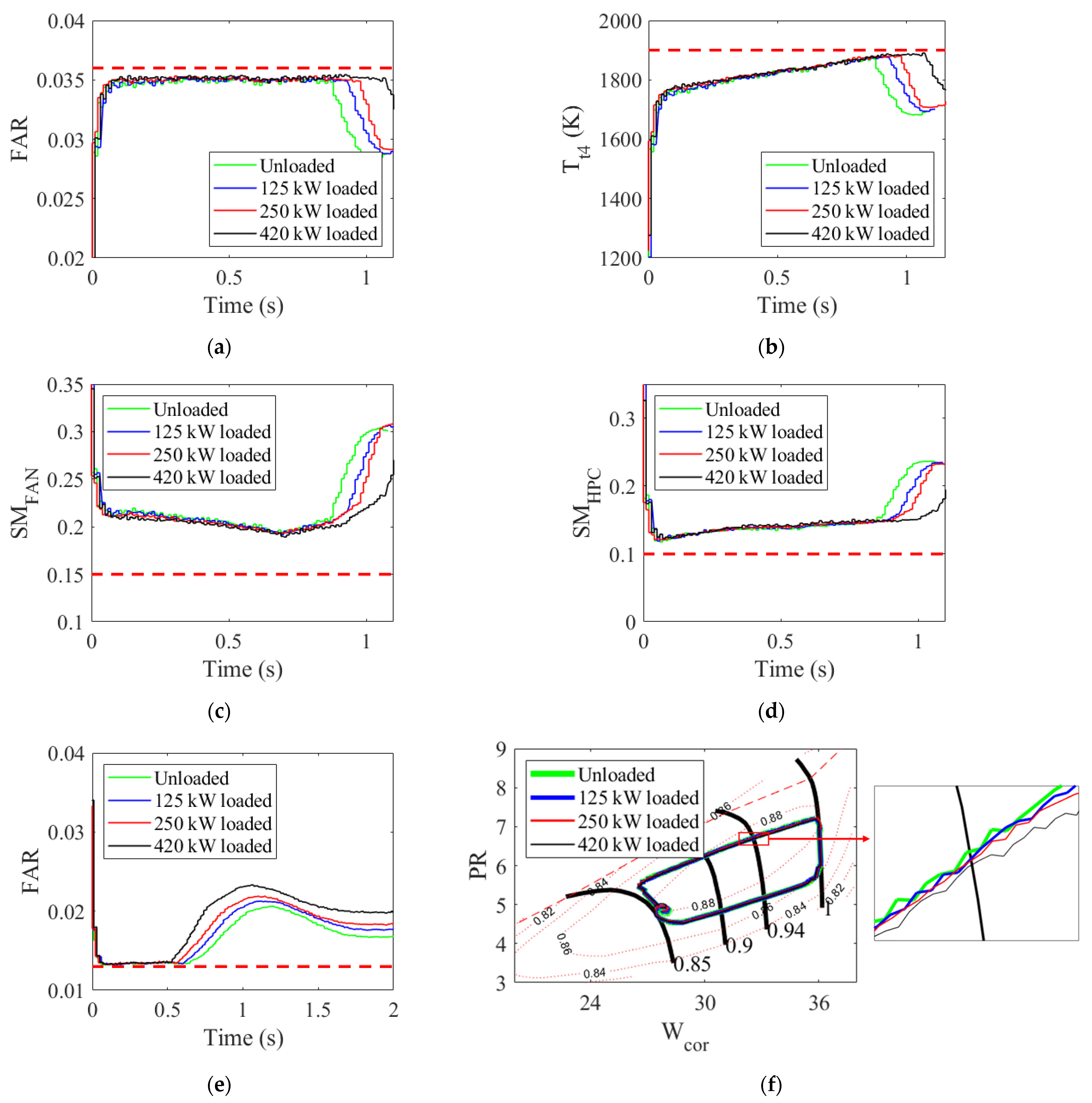
3.2. Cooperative Control Method for Acceleration/Deceleration Process

The acceleration/deceleration control of aero engines is a challenging task, accounting for approximately 75% of the total engine control law design efforts [34]. The coupling of SG adds another factor that needs to be considered in the acceleration/deceleration control law design.
The acceleration/deceleration cooperative control studied in this section represents only a tiny portion of the overall design for acceleration/deceleration control. This section focuses on investigating the impact of introducing SG on over-temperature, surge, and flameout protection during the acceleration/deceleration process. The essence of aero engine acceleration/deceleration control lies in limiting the fuel adjustment. During engine acceleration, if the fuel is increased too rapidly, it may lead to issues such as compressor surge, exceeding turbine inlet temperature limit, and combustion-chamber-rich fuel flameout. During engine deceleration, if the fuel is reduced too quickly, it may induce lean fuel flameout in the combustion chamber.
The solid blue line in Figure 8 represents the working point trajectory of the compressor during the acceleration/deceleration process, considering over-temperature, surge, and flameout restrictions. However, when SG is in the generator mode, the torque load from power generation acts on the engine shaft, causing a deviation in the working point trajectory of the rotor. The dashed red line in Figure 8 represents the working point trajectory of the compressor during the acceleration/deceleration process with power generation loads. With the impact of power generation loads, the acceleration curve is closer to the surge boundary, making the engine more susceptible to over-temperature, surge, and flameout. Considering the power generation loads, the deceleration curve becomes more conservative and closer to the common operating line.
The cooperative control for the acceleration/deceleration process requires consideration of the impact of the power generation load on the shaft. During acceleration, fuel is further restricted based on the magnitude of the power generation load, with a larger power generation load leading to a smaller limit on acceleration fuel. During deceleration, the minimum fuel limit is relaxed based on the magnitude of the power generation load, with a larger power generation load resulting in a smaller limit on deceleration fuel. This adjustment aims to bring the dashed trajectory in Figure 8 closer to the solid trajectory.
P SG refers to the power output of the starter generator. As shown in Figure 9, the cooperative control method for the acceleration/deceleration process adopts the classical min-max method. The acceleration/deceleration fuel-to-air ratio limits are obtained through interpolation based on relative conversion speed and power generation. The magnitude of the power generation affects the limits of the acceleration/deceleration fuel-to-air ratio. After calculating the fuel limit through the fuel-to-air ratio, the limit is compared with the fuel flow value calculated by the steady-state controller to obtain the minimum value. Then, the obtained value is compared with the deceleration fuel limit value to obtain the maximum value as the final fuel command. The final output is the acceleration/deceleration fuel command considering over-temperature, surge, flameout protection, and the impact of power generation.

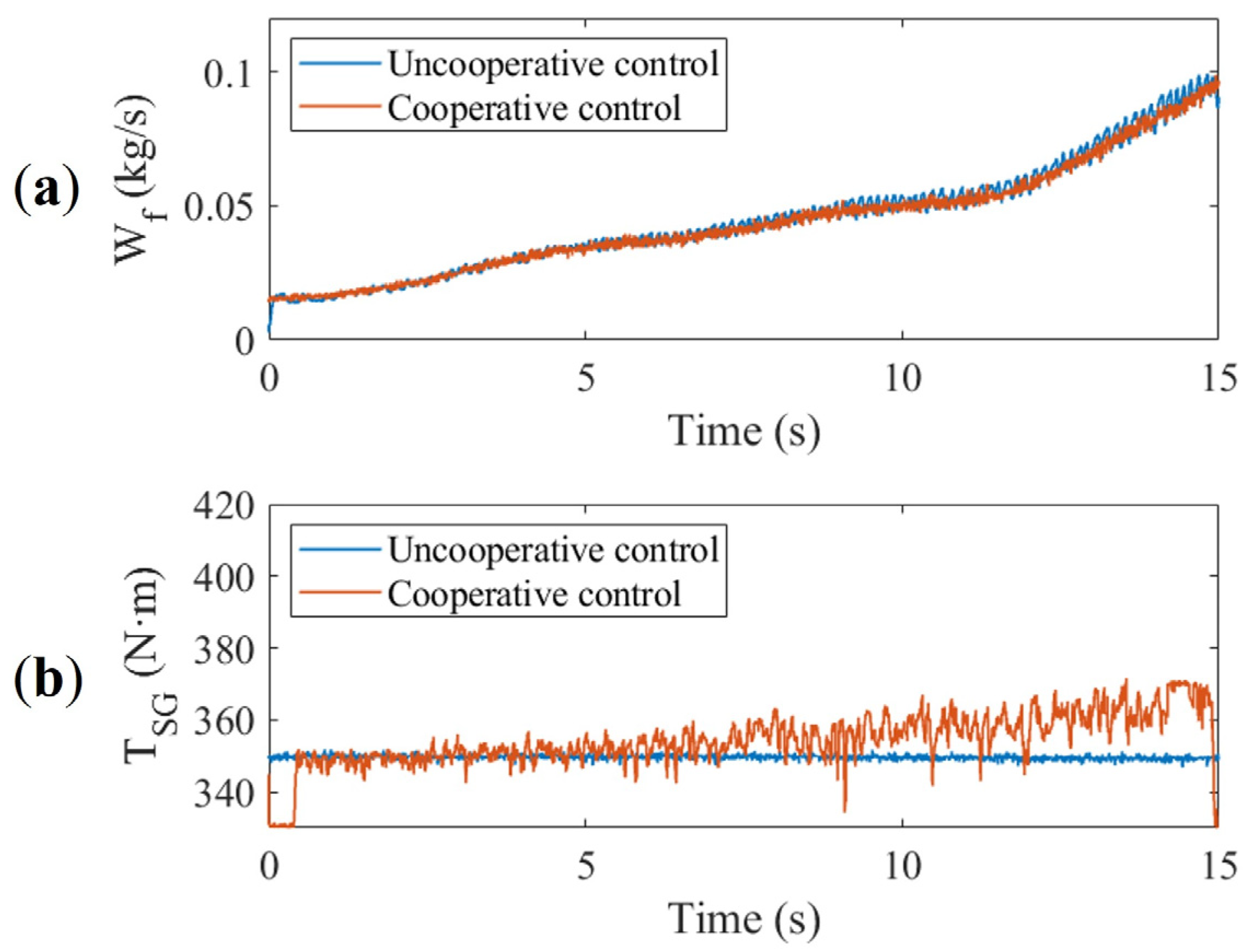
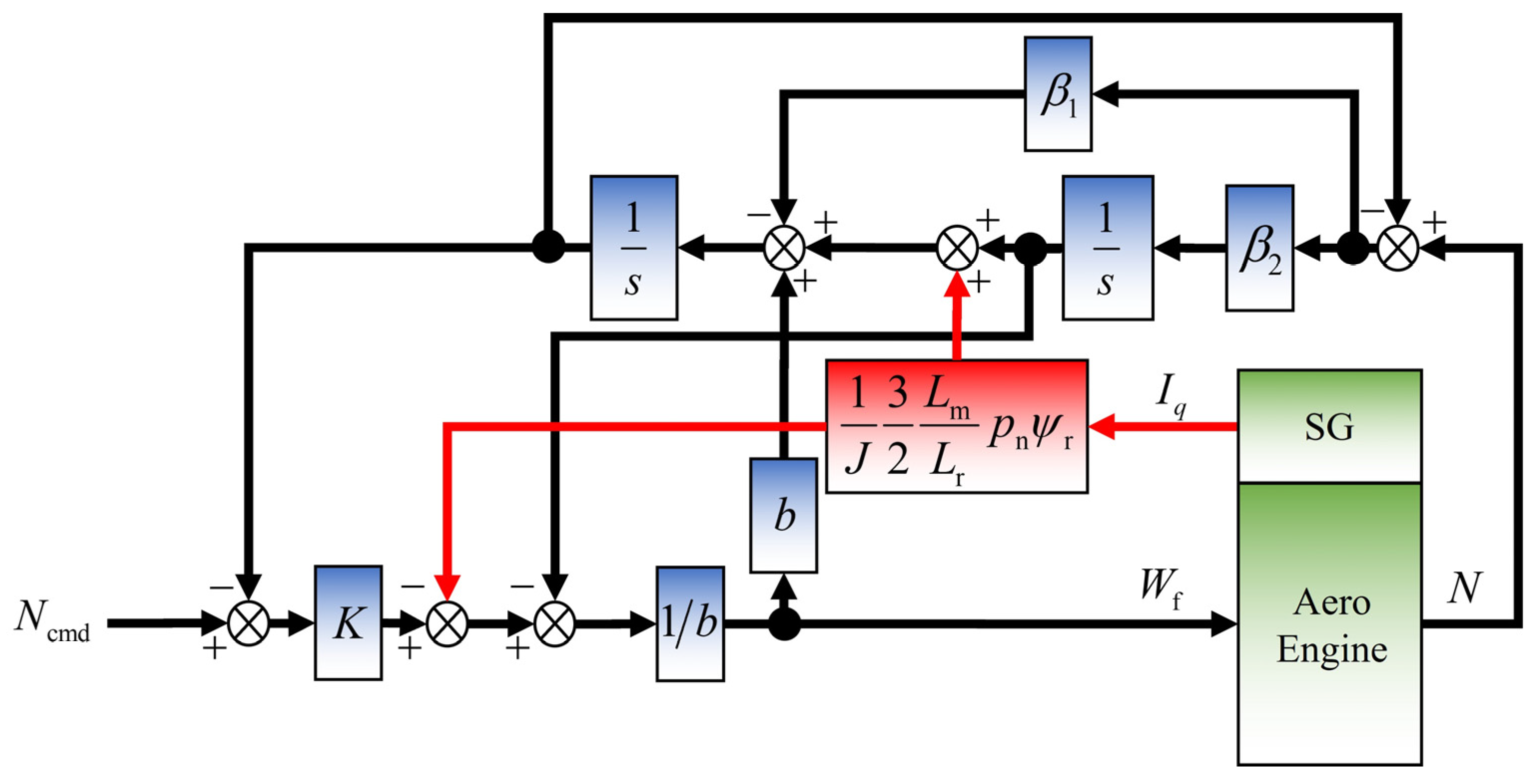
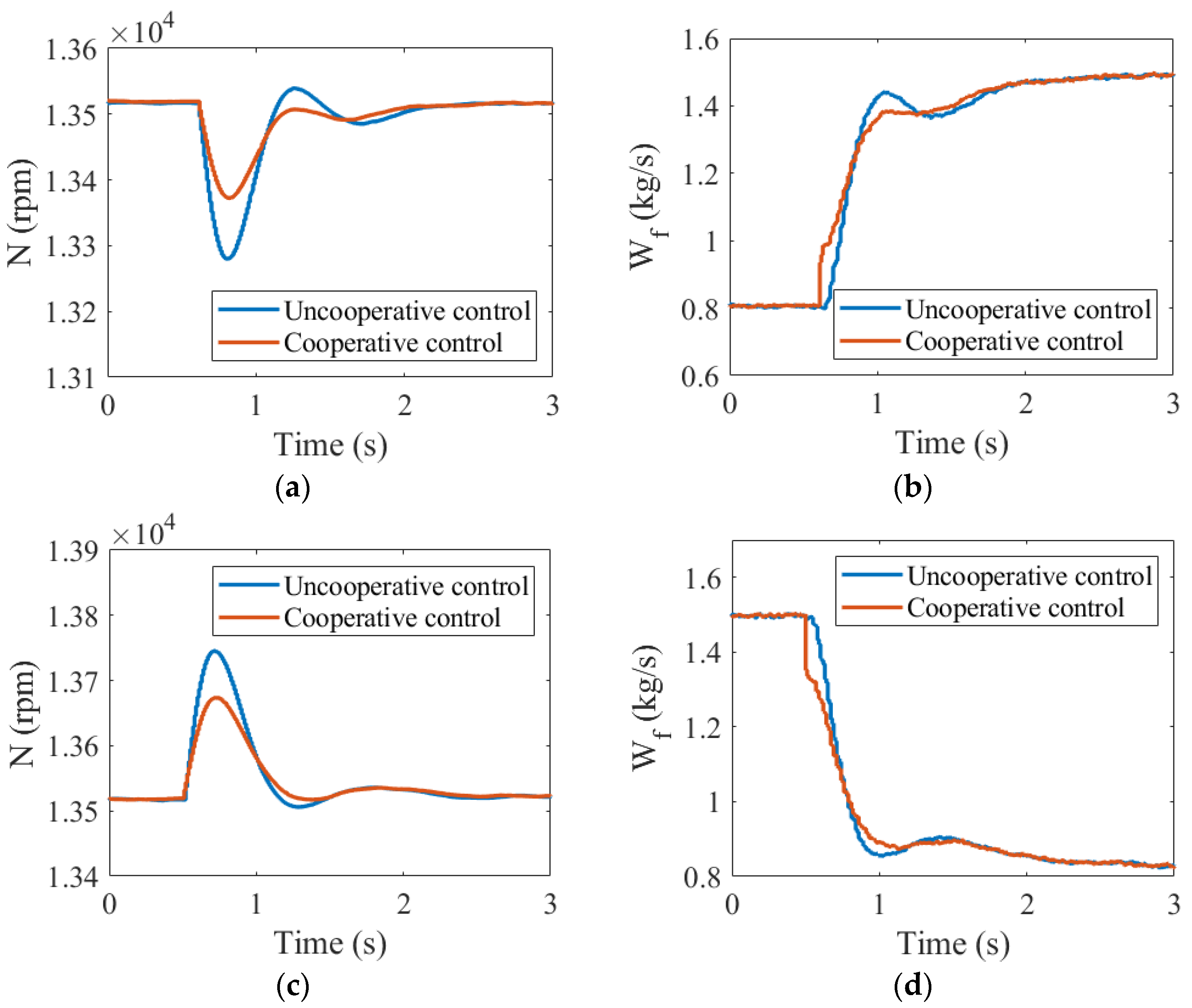
3.3. Cooperative Control Method for Steady-State Process

The objective of steady-state control for aero engines is to maintain stable engine speed, ensuring consistent engine thrust. However, variations in power generation from the generator can lead to fluctuations in the load torque acting on the engine shaft, resulting in engine speed and thrust fluctuations. Next, we will analyze the coupling between an aero engine and SG mechanistically in steady-state control.
The rotor dynamic equation of the aero engine needs to incorporate the influence of the SG torque. The impact of sliding friction torque during power generation is minimal and can be disregarded.
J d N d t = T HPT T HPC T SG ,
According to the principle of aero engine, the HP turbine output torque T HPT and the HP compressor load torque T HPC can be considered functions of the rotational speed N and fuel flow rate W f . Upon first-order expansion, they can be approximately described as follows:
T HPT = T HPT 0 + T HPT N Δ N + T HPT W f Δ W f ,
T HPC = T HPC 0 + T HPC N Δ N + T HPC W f Δ W f ,
For an induction-type SG, the load torque T SG during power generation is directly related to the control variable, which is the stator q-axis current I q . Upon first-order expansion, it can be described as follows:
T SG = T SG 0 + d T SG d I q Δ I q ,
In the equation, d T SG d I q can be approximated as a constant within the normal operating range of SG. For example, in the case of an induction-type SG, d T SG d I q can be described as follows:
d T SG d I q = 3 2 L m L r p n ψ r ,
If the first-order expansion point is chosen as the rotor equilibrium point, then T HPT 0 = T HPC 0 + T SG 0 . Substituting Equations (13)–(16) into Equation (12), we obtain the following:
d N d t = 1 J T HPT T HPC N N N 0 1 J T HPT T HPC W f W f 0 1 J 3 2 L m L r p n ψ r I q 0 + 1 J 3 2 L m L r p n ψ r I q + 1 J T HPT T HPC W f W f ,
where N 0 , W f 0 , and I q 0 are the steady-state values at equilibrium. J , L m , L r , p n , and ψ r refer to rotational inertia of the high-pressure shaft, magnetizing inductance, leakage inductance of rotor winding, number of pole pairs, and rotor magnetic flux. The impact of the generator on the steady-state speed control can be visually observed from the above equation. The entire term in the square bracket of Equation (17) is considered as the unknown dynamics of the system. Here, the focus is on the two terms outside the square bracket, where the term involving engine fuel flow rate W f is crucial for engine speed control. Adjusting the fuel can control the stability of the speed when there are fluctuations. The term involving generator quadrature current I q is a disturbance term. When there are electrical load fluctuations, the generator adjusts the quadrature current I q to control the stability of the voltage. However, the change also affects the stability of the speed.
The cooperative control for the steady-state process requires mitigating the impact of electrical load fluctuations on speed disturbances through compensatory control. Building upon Qiu’s linear active disturbance rejection control algorithm for steady-state control of auxiliary power unit during power generation [10], this section proposes a linear active disturbance rejection algorithm based on q-axis current compensation, aiming to enhance the engine’s ability to resist speed disturbances caused by power generation load fluctuations in steady-state control.
β 1 , β 2 , b , K refer to adjustable controller parameters. As shown in Figure 10, by adding a q-axis current feedforward channel in the linear active disturbance rejection control algorithm, the engine can anticipate changes in the power generation load torque. This enables the engine to adjust fuel in advance before speed disturbances occur, thereby reducing the impact of sudden power generation load variations on the stability of engine speed.

4. Hardware-in-the-Loop Simulation Platform

To validate the control method for a multi-electric aero engine with SG coordination, a hardware-in-the-loop simulation platform is constructed as shown in Figure 11. This platform includes an aero engine simulator, an SG simulator, a rapid prototyping controller for cooperative control, and the corresponding monitoring computers.
The hardware used for the aero engine simulator is the RobustRIO U818 developed by China Mango Tree Digital Technology Co., Ltd. (Suzhou City, China). It primarily features an Intel CPU + FPGA architecture and can be used to develop the measurement and control system based on LabVIEW 2019 software. It employs an Intel J4125 processor with a maximum frequency of 2.7 GHz. The FPGA utilizes Spartan-6 Lx75, equipped with 93,296 flip-flop triggers and a built-in real-time clock with a frequency of 40 MHz.
The SG simulator and the rapid prototyping controller utilize the same hardware platform developed based on Texas Instruments’ TM4C1294 chip. This chip features an ARM Cortex-M4F core with a clock frequency of up to 120 MHz. The hardware platform is equipped with functions such as analog signal acquisition, analog signal output, and frequency signal acquisition. During hardware-in-the-loop simulation, the speed signal is transmitted through frequency signal, while other physical quantities are transmitted using calibrated analog signals.
As shown in Figure 12, both the aero engine simulator and the host computer monitor are developed based on RobustRIO. The host computer monitor can send control commands to the rapid prototyping controller, including start boolean and power lever angle (PLA) commands. Simultaneously, the host computer monitor can send power generation commands to influence the electrical load when the SG model generates power. The model state parameters in the aero engine and the SG simulators are transmitted to the host computer monitor and displayed on the monitoring interface. During the starting process, the rapid prototyping controller needs to coordinate the torque of SG and the fuel flow of the aero engine. During the power generation process, the rapid prototyping controller adjusts the engine fuel flow based on the q-axis current compensation for the steady-state process and limit value adjustment for the acceleration/deceleration process to mitigate the adverse effects of SG coupling. The coupling effects are reflected in the speed and torque transmission between the SG simulator and the aero engine simulator. The cooperative controller monitor can perform configuration of the rapid prototyping controller parameters to achieve optimal control effectiveness. The SG model monitor can configure the parameters of the SG model to conduct hardware-in-the-loop simulation experiments involving aero engines and various SGs.
Due to the inertia differences between the aero engine and SG, the simulation step for the aero engine model is set to 10 ms, while the step for the external characteristic model of SG is set to 1 ms. The control step in the rapid prototyping controller is set to 20 ms, consistent with the conventional engine control.

5. Simulation Results and Analysis

Cooperative control simulation experiments are conducted on the hardware-in-the-loop simulation platform, including the starting process, acceleration/deceleration process, and steady-state process. The experiments aim to demonstrate the necessity of considering SG coordination in muti-electric aero engine control through comparative analysis. Cooperative control allows for the full utilization of the SG’s advantages and helps mitigate disturbances caused by coupling. Finally, a hardware-in-the-loop simulation experiment is performed for a complete flight mission.

5.1. Starting Process

The comparative analysis of the starting process primarily focuses on stage II in Figure 6, in which the torque generated by SG and the torque produced by fuel combustion collectively drive the rotor to follow the acceleration control schedule of the starting process.
The blue line in Figure 13 represents the variation in fuel flow and SG torque over time without considering coordination. The SG torque maintains a constant output, while the engine fuel system uses closed-loop control to regulate rotor acceleration, resulting in oscillations of controlled acceleration during engine fuel adjustment. With coordination considered, the control quantity variation is depicted by the red line in Figure 13. Engine fuel is controlled through open-loop control based on the air–fuel ratio schedule, and the SG torque is used for closed-loop control of rotor acceleration.
The torque response of SG is significantly faster than the response of the torque generated by fuel combustion. Therefore, in terms of the control effect on acceleration shown in Figure 14, the oscillation in acceleration after coordination control is noticeably improved compared to the oscillation when coordination control is not considered.

5.2. Acceleration/Deceleration Process

During the acceleration/deceleration process of the aero engine, the load torque generated by SG when generating power can alter the engine’s operational state. Therefore, cooperative control of a multi-electric engine during the acceleration/deceleration process needs to consider the impact of power generation.
Figure 15 illustrates the comparison of the acceleration/deceleration process under different electrical load conditions with cooperative control. Figure 15a–d depict the variation of limiting protection parameters over time during the acceleration process. Under various electrical loads, the air–fuel ratio in the combustion chamber, the total temperature at the inlet of the high-pressure turbine, and the surge margin of the fan and high-pressure compressor are all constrained within the specified limits. Figure 15e illustrates the air–fuel ratio variation in the combustion chamber over time during the deceleration process under different electrical load conditions, with the air–fuel ratio consistently constrained above the flameout ratio. Figure 15f presents the trajectory of the high-pressure compressor operating point during the acceleration/deceleration process under different electrical loads. With cooperative control, the acceleration/deceleration can mitigate the impact of electrical loads, and the operating point trajectory aligns as closely as possible with the trajectory under no load.

5.3. Steady-State Process

When the aero engine is operating in a steady state, such as during a cruise condition, the state of the engine is unexpectedly influenced by external disturbances. During the power generation process with variable electrical loads, the significant load transients can lead to sudden engine speed and thrust changes, affecting flight safety. The cooperative control for the steady-state process is based on compensating the fuel flow by the q-axis current of SG to adjust the fuel flow in advance of speed changes, mitigating the impact of electrical load fluctuations on speed.
Figure 16a,b depict the disturbance rejection control effect on engine speed when a sudden electrical load is applied. By comparing the cooperative control effect that compensates fuel through the q-axis current with the uncooperative control effect that does not consider SG, it is evident that cooperative control results in a significant reduction in speed disturbance amplitude. Additionally, the fuel adjustment in the early stage after disturbance is timelier with cooperative control compared to uncooperative control. Figure 16c,d illustrate the disturbance rejection control effect on engine speed when a sudden electrical load is unloaded, demonstrating the advantage of the cooperative control method for the steady-state process.

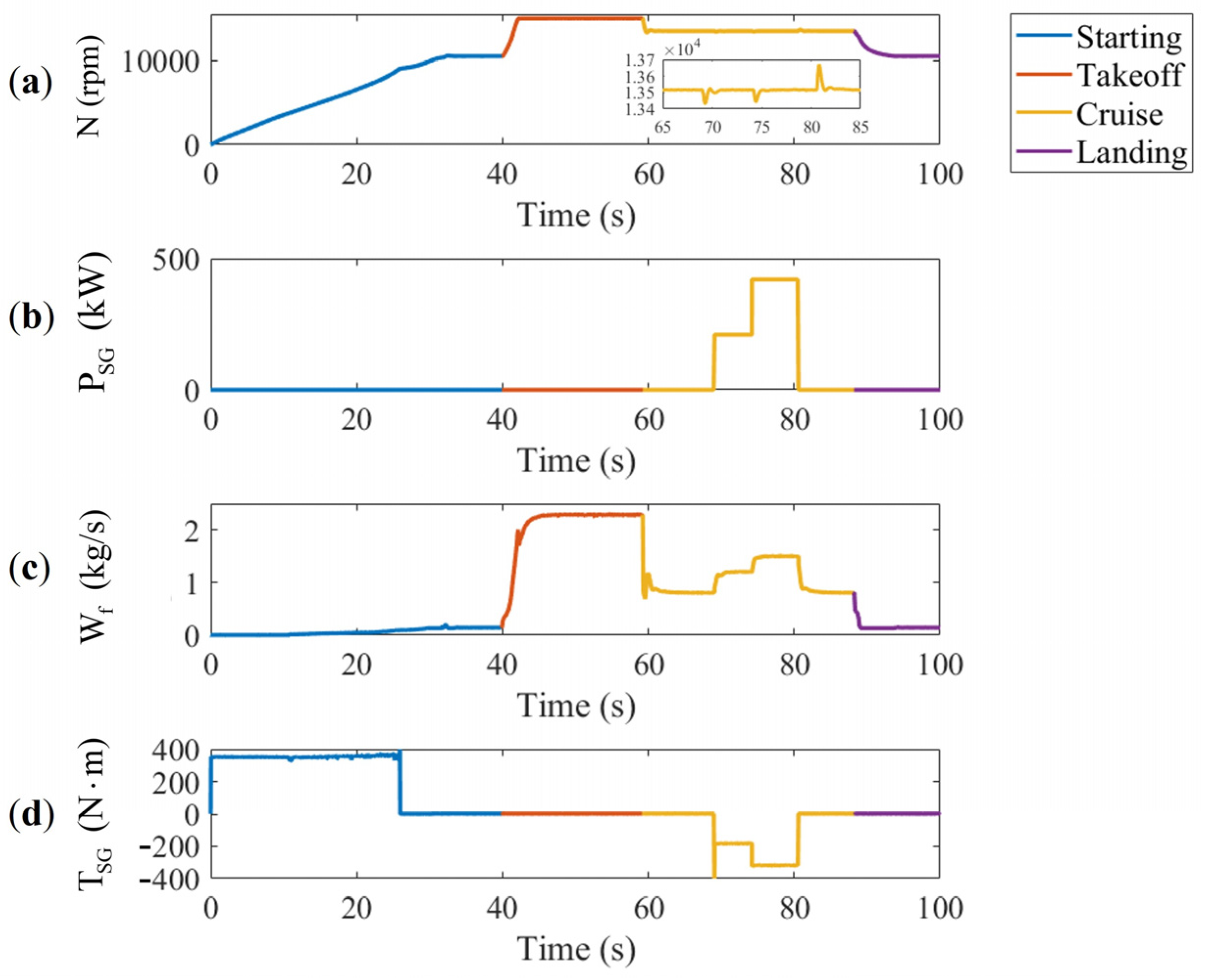
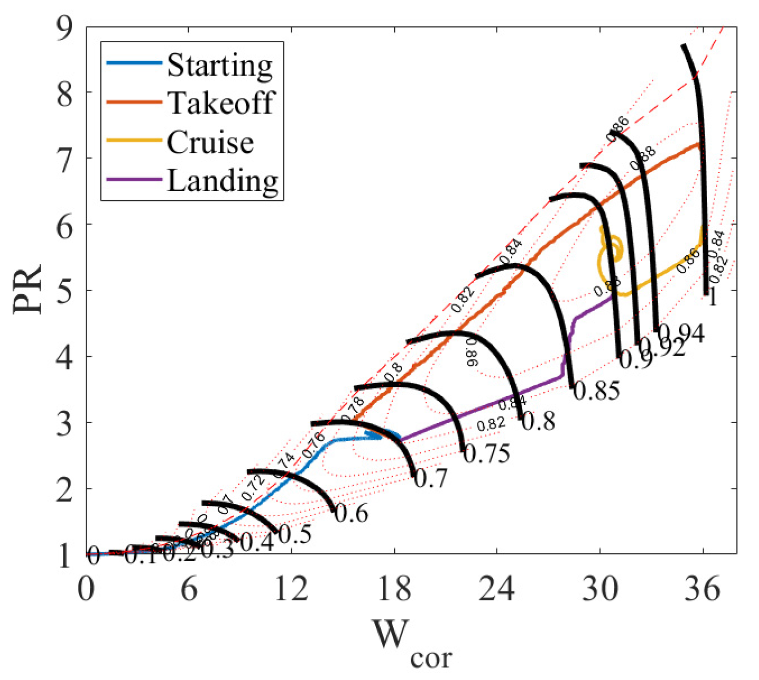
5.4. A Complete Flight Mission

Finally, a hardware-in-the-loop simulation is conducted for the multi-electric aero engine in a complete flight mission, encompassing starting from the ground, reaching maximum thrust during takeoff, transitioning to power generation with various electrical loads at the cruise operating point, and ultimately decreasing the speed in preparation for landing.
Figure 17 depicts the variations over time in engine speed, power of generation, engine fuel flow, and SG torque. The SG torque is positive during the starting process, while it is negative during the power generation process. The peak in generator torque around 70 s is caused by an excessive adjustment of the q-axis current when the load is first connected.
The cooperative control methods during starting, acceleration/deceleration, and steady-state processes operate generally throughout the entire mission, and the system maintains stability during control method transitions.
The compressor’s complete operating point trajectory is shown in Figure 18. Whether during acceleration/deceleration or fluctuations in electrical loads, the compressor consistently operates within a stable working range.

6. Conclusions

This paper comprehensively considers the interaction between SG and aero engine and establishes a multi-electric aero engine model for cooperative control research. The study proposes multi-electric aero engine control methods with SG coordination for starting, acceleration/deceleration, and steady-state processes. A hardware-in-the-loop simulation platform for the cooperative control research is constructed, consisting of an aero engine simulator, an SG simulator, and a rapid prototyping controller. Simulation results validate the advantages of the cooperative control compared to the decentralized control. The main conclusions are summarized as follows:
  • The application of the rotor’s full-state characteristics to the aero engine model enhances the simulation capability at low-speed states.
  • The external characteristic modeling method used to establish the SG model sacrifices high-frequency dynamics but enables real-time simulation of the SG model on conventional embedded platforms.
  • The cooperative control of SG torque and aero engine fuel during the starting process can reduce the oscillation of the acceleration.
  • The adjustment of fuel limiting values based on electrical load power during the acceleration/deceleration process can reduce the impact of electrical load on protection limits such as over-temperature, surging, and flameout, ensuring safety and stability under different electrical load conditions.
  • A cooperative control method for the steady-state process is proposed to compensate fuel based on the q-axis current of SG, reducing the amplitude of engine speed fluctuations caused by sudden electrical load disturbances.

Author Contributions

Conceptualization, J.F. and T.Z.; methodology, J.F.; software, J.F.; validation, J.F., T.Z. and Z.C.; formal analysis, J.F.; investigation, J.F.; resources, E.T.; data curation, J.F.; writing—original draft preparation, J.F.; writing—review and editing, T.Z. and Z.C.; visualization, J.F. and E.T.; supervision, E.T.; project administration, T.Z.; funding acquisition, T.Z. All authors have read and agreed to the published version of the manuscript.

Funding

This work was supported by the National Natural Science Foundation of China (Grant number: 51976089).

Data Availability Statement

Data are contained within the article.

Acknowledgments

The authors thank Zhang Tianhong for his guidance on this paper and the help of students from our research office.

Conflicts of Interest

The authors declare no conflicts of interest.

Abbreviations

The following abbreviations are used in this manuscript:
DCDirect current
EPTElectric power transfer
FARAir–fuel ratio
f sliding Sliding friction torque
f static Static friction torque
HPHigh-pressure
I q q-axis current
J H ( J ) Rotational inertia of the high-pressure shaft
J L Rotational inertia of the low-pressure shaft
LPLow-pressure
L r Leakage inductance of rotor winding
L m Magnetizing inductance
N cor Relative converted speed
N H ( N ) High-pressure shaft speed
N L Low-pressure shaft speed
N dot Rotational acceleration
N cmd Speed command
PRPressure ratio
PLAPower level angle
P SG Power output of the starter generator
P t 3 Total pressure at the HP compressor outlet section
P tin Inlet total pressure
P tout Outlet total pressure
p n Number of pole pairs
SGStarter generator
SFCSpecific fuel consumption
SM FAN Fan surge margin
SM HPC High-pressure compressor surge margin
TEEMTurbine electrical energy management
T FAN Fan torque
T HPC High-pressure compressor torque
T HPT High-pressure turbine torque
T LPT Low-pressure turbine torque
T SG Starter generator torque
T cmd Torque command
T t 2 Total temperature at the fan inlet section
T t 4 Total temperature at the HP turbine inlet section
T tin Inlet total pressure
T tout Outlet total pressure
W cor Converted flow rate
W f Fuel flow rate
ψ r Rotor magnetic flux
β 1 ,   β 2 ,   b ,   K Adjustable controller parameters

References

  1. Simon, D.L.; Connolly, J.W.; Culley, D.E. Control technology needs for electrified aircraft propulsion systems. J. Eng. Gas Turbines Power-Trans. ASME 2020, 142, 011025. [Google Scholar] [CrossRef]
  2. Jansen, R.; Bowman, C.; Jankovsky, A.; Dyson, R.; Felder, J. Overview of NASA electrified aircraft propulsion (EAP) research for large subsonic transports. In Proceedings of the 53rd AIAA/SAE/ASEE Joint Propulsion Conference, Atlanta, GA, USA, 10–12 July 2017. [Google Scholar]
  3. Adibhatla, S.; Garg, S.; Griffith, S.; Karnofski, K.; Payne, N.; Wood, B. Propulsion control technology development roadmaps to address nasa aeronautics research mission goals for thrusts 3a and 4. In Proceedings of the 2018 Joint Propulsion Conference, Cincinnati, OH, USA, 9–11 July 2018. [Google Scholar]
  4. Welstead, J.R.; Felder, J.L. Conceptual design of a single-aisle turboelectric commercial transport with fuselage boundary layer ingestion. In Proceedings of the 54th AIAA Aerospace Sciences Meeting, San Diego, CA, USA, 4–8 January 2016. [Google Scholar]
  5. Kratz, J.L.; Thomas, G.L. Dynamic analysis of the STARC-ABL propulsion system. In Proceedings of the AIAA Propulsion and Energy 2019 Forum, Indianapolis, IN, USA, 19–22 August 2019. [Google Scholar]
  6. Kim, H.D.; Felder, J.L.; Tong, M.T.; Berton, J.J.; Haller, W.J. Turboelectric distributed propulsion benefits on the N3-X vehicle. Aircr. Eng. Aerosp. Technol. 2014, 86, 558–561. [Google Scholar] [CrossRef]
  7. McNab, I.R. Pulsed power for electric guns. IEEE Trans. Magn. 1997, 33, 453–460. [Google Scholar] [CrossRef]
  8. Mohamed, M.A.A.; Shen Yeoh, S.; Atkin, J.; Diab, A.M.; Khalaf, M.; Bozhko, S. Enhanced starting control scheme for PMM-based starter/generator system for MEA. Aerospace 2023, 10, 168. [Google Scholar] [CrossRef]
  9. Liu, H.; Bu, F.; Huang, W.; Xu, H.; Degano, M.; Gerada, C. Control-winding direct power control strategy for five-phase dual-stator winding induction generator DC generating system. IEEE Trans. Transp. Electrif. 2020, 6, 73–82. [Google Scholar] [CrossRef]
  10. Qiu, X.; Zhang, Y.; Li, Y. Active disturbance rejection control method of auxiliary power unit. J. Aerosp. Power 2024, 39, 20220035. [Google Scholar]
  11. Simon, D.L.; Bianco, S.J.; Horning, M. Integrated control design for a partially turboelectric aircraft propulsion system. J. Eng. Gas Turbines Power 2023, 146, 1–37. [Google Scholar] [CrossRef]
  12. Connolly, J.W.; Chapman, J.W.; Stalcup, E.J.; Chicatelli, A.; Hunker, K.R. Modeling and control design for a turboelectric single aisle aircraft propulsion system. In Proceedings of the 2018 AIAA/IEEE Electric Aircraft Technologies Symposium, Cincinnati, OH, USA, 12–13 July 2018. [Google Scholar]
  13. Seok, J.; Reed, D.M.; Kolmanovsky, I.V.; Girard, A.R. Coordinated model predictive control of aircraft gas turbine engine with simplified electrical system model. In Proceedings of the American Control Conference, Milwaukee, WI, USA, 27–29 June 2018. [Google Scholar]
  14. Seok, J.; Kolmanovsky, I.; Girard, A. coordinated model predictive control of aircraft gas turbine engine and power system. J. Guid. Control. Dyn. 2017, 40, 2538–2555. [Google Scholar] [CrossRef]
  15. Seok, J.; Kolmanovsky, I.; Girard, A. Integrated/Coordinated control of aircraft gas turbine engine and electrical power system: Towards large electrical load handling. In Proceedings of the 55th IEEE Conference on Decision and Control (CDC), Las Vegas, NV, USA, 12–14 December 2016. [Google Scholar]
  16. Richter, H.; Connolly, J.W.; Simon, D.L. Optimal control and energy management for hybrid gas-electric propulsion. J. Eng. Gas Turbines Power 2020, 142, 091009. [Google Scholar] [CrossRef]
  17. Wei, Z.; Ma, Y.; Xiang, C.; Liu, D.; Li, Z.; Ruan, S. An energy-saving regulation approach based on economic rotational speed and power split feature for more electric turboshaft engine. Aerosp. Sci. Technol. 2022, 130, 107913. [Google Scholar] [CrossRef]
  18. Culley, D.E.; Kratz, J.L.; Thomas, G.L. Turbine electrified energy management (TEEM) for enabling more efficient engine designs. In Proceedings of the 2018 Joint Propulsion Conference, Cincinnati, OH, USA, 9–11 July 2018. [Google Scholar]
  19. Enalou, H.B.; Lang, X.; Rashed, M.; Bozhko, S. Time-scaled emulation of electric power transfer in the more electric engine. IEEE Trans. Transp. Electrif. 2020, 6, 1679–1694. [Google Scholar] [CrossRef]
  20. Electrical Modeling and Thermal Analysis Toolbox (EMTAT) User’s Guide. Available online: https://ntrs.nasa.gov/citations/20205008125 (accessed on 28 October 2020).
  21. NASA Electric Aircraft Test Bed (NEAT) Development Plan-Design, Fabrication, Installation. Available online: https://ntrs.nasa.gov/citations/20160010440 (accessed on 1 July 2016).
  22. Hybrid-Electric Aero-Propulsion Controls Testbed Results. Available online: https://ntrs.nasa.gov/citations/20220016701 (accessed on 4 November 2022).
  23. Bretschneider, S.; Reed, J. Modeling of start-up from engine-off conditions using high fidelity turbofan engine simulations. J. Eng. Gas Turbines Power-Trans. ASME 2016, 138, 051201. [Google Scholar] [CrossRef]
  24. Ferrer-Vidal, L.E.; Iglesias-Perez, A.; Pachidis, V. Characterization of axial compressor performance at locked rotor and torque-free windmill conditions. Aerosp. Sci. Technol. 2020, 101, 105846. [Google Scholar] [CrossRef]
  25. Extended Parametric Representation of Compressor Fans and Turbines Volume I—CMGEN User’s Manual. Available online: https://ntrs.nasa.gov/citations/19860014465 (accessed on 1 March 1984).
  26. Extended Parametric Representation of Compressor Fans and Turbines Volume II—PART User’s Manual. Available online: https://ntrs.nasa.gov/citations/19860014466 (accessed on 1 March 1984).
  27. Extended Parametric Representation of Compressor Fans and Turbines Volume III MODFAN User’s Manual. Available online: https://ntrs.nasa.gov/citations/19860014467 (accessed on 1 March 1984).
  28. Shi, Y.; Tu, Q.; Yan, H.; Jiang, P.; Cai, Y. A full states performance model for aero engine. J. Aerosp. Power 2017, 32, 373–381. [Google Scholar] [CrossRef]
  29. Bu, F.; Hu, Y.; Huang, W.; Zhuang, S.; Shi, K. Wide-speed-range-operation dual stator-winding induction generator dc generating system for wind power applications. IEEE Trans. Power Electron. 2015, 30, 561–573. [Google Scholar] [CrossRef]
  30. Thomas, G.L.; Culley, D.E.; Kratz, J.L.; Fisher, K.L. Dynamic analysis of the hfan, a parallel hybrid electric turbofan engine. In Proceedings of the 2018 Joint Propulsion Conference, Cincinnati, OH, USA, 9–11 July 2018. [Google Scholar]
  31. Subsonic Ultra Green Aircraft Research: Phase II—Volume II—Hybrid Electric Design Exploration. Available online: https://ntrs.nasa.gov/citations/20150017039 (accessed on 1 April 2015).
  32. Kong, X.; Wang, X.; Zhang, S.; Yin, C. Research and experiment on improved sectional combination control scheme for civil turbofan engine’s startup process. J. Aerosp. Power 2014, 29, 2924–2929. [Google Scholar]
  33. Yao, T.; Wen, W.; Yang, G.; Wang, Y.; Zhu, A. Control law design for n-dot closed control loop for acceleration and deceleration process in turbofan engine. J. Propuls. Technol. 2020, 41, 1404–1410. [Google Scholar]
  34. Jaw, L.C.; Mattingly, J.D. Aircraft Engine Controls: Design, System Analysis and Health Monitoring; American Institute of Aeronautics and Astronautics: Reston, VA, USA, 2009; pp. 119–142. [Google Scholar]
Figure 1. Full-state characteristics during the starting process [23,24].
Aerospace 11 00271 g001
Figure 2. Speed variation during starting process.
Aerospace 11 00271 g002
Figure 3. Fan operating point trajectory during the starting process.
Aerospace 11 00271 g003
Figure 4. Diagram illustrating SG modeling method for external characteristics.
Aerospace 11 00271 g004
Figure 5. Comparison of external characteristics model and electromagnetic model: (a) generating voltage, (b) generating current, (c) starter generator torque.
Aerospace 11 00271 g005
Figure 6. Acceleration control schedule for starting process.
Aerospace 11 00271 g006
Figure 7. Cooperative control method for starting process.
Aerospace 11 00271 g007
Figure 8. The impact of power generation on acceleration/deceleration.
Aerospace 11 00271 g008
Figure 9. Cooperative control min-max method for acceleration/deceleration process.
Aerospace 11 00271 g009
Figure 10. Linear active disturbance rejection algorithm based on q-axis current compensation.
Aerospace 11 00271 g010
Figure 11. Hardware-in-the-loop simulation platform.
Aerospace 11 00271 g011
Figure 12. Structure diagram of hardware-in-the-loop simulation.
Aerospace 11 00271 g012
Figure 13. Comparison chart of time-varying control quantity: (a) fuel flow rate, (b) starter generator torque.
Aerospace 11 00271 g013
Figure 14. Comparison chart of acceleration control effects.
Aerospace 11 00271 g014
Figure 15. Comparison chart of acceleration/deceleration process under different electrical load conditions: (a) air–fuel ratio during acceleration, (b) total temperature at the HP turbine inlet section during acceleration, (c) fan surge margin during acceleration, (d) high-pressure compressor surge margin during acceleration, (e) air–fuel ratio during deceleration, (f) HPC operating point trajectory.
Aerospace 11 00271 g015
Figure 16. Comparison chart of disturbance rejection control effects during sudden electrical load transients: (a) speed at sudden loading, (b) fuel flow rate at sudden loading, (c) speed at sudden unloading, (d) fuel flow rate at sudden unloading.
Aerospace 11 00271 g016
Figure 17. Key parameters variations in a complete flight mission: (a) high-pressure shaft speed, (b) power output of the starter generator, (c) fuel flow rate, (d) starter generator torque.
Aerospace 11 00271 g017
Figure 18. Compressor operating point trajectory in a complete flight mission.
Aerospace 11 00271 g018
Table 1. Parameter ranges of full-state characteristics.
StatesIsentropic EfficiencyInlet/Outlet Conditions
Compressor η 0 , 1 T tout > T tin P tout / P tin > 1
Stirrer or Paddle η , 0 T tout > T tin P tout / P tin < 1
Turbine η 1 , + T tout < T tin P tout / P tin < 1
Table 2. Fan flow balance during the starting process.
Judgment CriteriaFan Flow BalanceSchematic Diagram
P R FAN P R BYPASS W FAN = W HPC Aerospace 11 00271 i001
P R FAN > P R BYPASS W FAN = W HPC + W BYPASS Aerospace 11 00271 i002
Table 3. Specifications of the studied turbofan engine at the design point.
ParametersValue
Bypass Ratio0.36
Overall Pressure Ratio30.1
Max Thrust (kN)106.346
SFC (kg/(N·h))0.0796
Inlet air mass flow (kg/s)134.57
Fuel mass flow (kg/s)2.35
Inlet HP turbine temperature (K)1850
LP shaft and HP shaft speeds (rpm)11,000, 15,000
Table 4. Specifications of the studied SG.
ParametersValue
Rated power (kW)420
Rated speed (rpm)13,500
Rated voltage of DC bus (V)270
Number of pole pairs1
Internal resistance of stator winding (mΩ)1.107
Internal resistance of rotor winding (mΩ)0.907
Magnetizing inductance (mH)0.171
Leakage inductance of stator winding (μH)2.913
Leakage inductance of rotor winding (μH)5.463
Disclaimer/Publisher’s Note: The statements, opinions and data contained in all publications are solely those of the individual author(s) and contributor(s) and not of MDPI and/or the editor(s). MDPI and/or the editor(s) disclaim responsibility for any injury to people or property resulting from any ideas, methods, instructions or products referred to in the content.

