1. Introduction
Martian soil and rocks play a crucial role as reservoirs of significant scientific information, providing essential insights for humanity to unravel the solar system’s mysteries and identify potential signs of life on Mars [
1,
2]. However, due to the challenges posed by space radiation and inhospitable conditions for microorganisms on the Martian surface, this study focuses on the durable Martian rocks beneath the regolith. These rocks are selected as the primary research subjects. The primary method employed for studying Martian rocks is the drilling core sampling technique, which emerges as a paramount approach for precisely understanding their properties. This method stands out as one of the most direct and effective means for gaining insights into the characteristics of Martian rocks [
3,
4,
5].
In 2003, Courage utilized tungsten carbide, along with four magnets of varying strengths, to develop the rock abrasion device integrated into this apparatus [
6]. In 2007, the Rover sampling rig employed tungsten carbide and surface diamond as the drill bit, coupled with a hollow stem configuration. Subsequently [
7], in 2011, Curiosity utilized a tungsten carbide drill bit for sample grinding and an auger stem for sample extraction [
8]. Finally, in 2022, Mole employed tungsten carbide in designing the hammered inline tube sampling device for sample collection [
9,
10]. However, when faced with the dense basalt on Mars [
11], all missions encountered consistent drilling difficulties and significant issues related to wear and tear.
In 2021, NASA initiated the Perseverance Mars rover mission, incorporating a tungsten carbide drill bit specifically tailored for Martian rock. Unfortunately, the initial drilling operation with Perseverance revealed considerable wear and tear on the drilling string. This poses a substantial challenge, particularly given the complexity of replacing the drilling string for multiple, multi-point samplings of the Martian rock profile [
12]. This underscores the crucial need for drilling string with prolonged durability, high wear resistance, and self-sharpening capabilities to ensure the reliability of the drilling process. In 2012, the University of Kentucky developed the PCD compact core drilling rig, as illustrated in
Figure 1, which utilized cemented carbide with impregnated diamonds as the drill bit. This configuration included four impregnated diamonds and four reaming grinding tools. Experimental measurements of the wear amount were conducted, verifying the configuration’s effectiveness in reducing wear [
13]. The findings of the study offer valuable insights for the design of the drill bit configuration proposed in this paper.
Moreover, given the substantial presence of life-related information and water ice material in Martian rocks, the effective mitigation of sample denaturation, resulting from frictional heat generation during the drilling process, has become a challenging aspect of the sample collection process. In the past, both Phoenix and Perseverance utilized insulating materials to isolate the samples [
14,
15,
16], whereas Courage and Curiosity lacked insulation [
17,
18]. The Drilling Integration Package for Scientific Drilling (DIBS) developed by Galileo Avionica [
19,
20] and the Mars Astrobiology Research and Technology Experiment (MARTE) drilling system developed by Honeybee Robotics Inc. [
21,
22,
23] enable samples to be directly transported to subsystems for in situ analysis, capturing the most realistic characteristics of the samples. However, this approach still does not fully address the issue of heat exposure during the drilling process.
We know from the above that, in recent years, compared to other star soil-drilling tools, previous drill bits have predominantly been composed of cemented carbide materials and utilized cutting methods for drilling. However, their thin and brittle cutting edges make them prone to chipping when drilling hard rocks, thus reducing the drill bit’s lifespan. Moreover, these drill bits have small heat dissipation areas and suboptimal thermal conductivity. In contrast, the designed impregnated diamond drill bit exhibits excellent self-sharpness and is resistant to chipping. Utilizing grinding for drilling, it boasts a larger heat dissipation area and superior material thermal conductivity.
In this paper, we propose the design of a sampling drill bit based on impregnated diamond. The aim is to mitigate the sample’s temperature rise by enhancing the drill bit’s configuration and optimizing the drilling process. This is achieved by efficiently directing frictional heat from the drill hole through the designed junk slot. The design also focuses on enhancing the self-sharpening capability and stabilizing performance during prolonged operations. This study extensively analyzes the rise in drilling efficiency, drilling force load, drill wear resistance, and sample temperature in various drilling conditions using the designed impregnated diamond drill bit for sampling Martian rocks. The study comprehensively examines drilling efficiency, force load, bit wear resistance, and sample temperature rise across diverse drilling scenarios.
2. Mars Sampling Bit Performance Requirements
- (1)
Self-sharpening requirements
As unmanned autonomous sampling is used, the drill bit of the drilling string is challenging to replace or repair when it is worn out. Therefore, the drill bit must exhibit self-sharpening performance to ensure efficient and stable sampling while maintaining the capability to conduct drilling steadily and in optimal conditions.
- (2)
Wear resistance requirements
Curiosity’s drill bit demonstrated the capability to penetrate dense basalt; however, it experienced significant wear, leading to a shortened bit life. Consequently, the drill was limited to drilling softer materials like limestone to ensure optimal drilling string performance, and the residual metal shavings from the drill bit can introduce errors in the detection results. To address these challenges, specific requirements are proposed for the material selection of the drill bit, emphasizing abrasion resistance. The design configuration must also meet the demand to minimize frictional heat generation and avoid leaving detectable residues.
- (3)
Temperature rise requirements
In the process of drilling samples, although dry drilling samples could prevent the samples from being contaminated, the drilling platform in the planet’s depth would make it difficult for the heat to be dispersed. This difficulty may compromise the abrasion resistance of the drilling string and, more critically, lead to sample denaturation, undermining its scientific value [
24]. Notably, Perseverance experienced significant heat generation during drilling, exceeding 500 °C. Therefore, using high-quality heat-resistant materials is imperative, and the drill bit configuration should be meticulously designed to minimize temperature rise as much as possible.
- (4)
Drilling performance requirements
The distribution of rocks on the surface of Mars exhibits high randomness. Through the examination of fundamental parameters such as Martian rock’s hardness, shear resistance, and compression resistance [
25,
26,
27,
28,
29,
30], the target characteristic parameters of Martian rocks are summarized in
Table 1. Core drilling string necessitates high hardness and efficient junk slots to address the complexities of drilling conditions effectively. Curiosity incorporated the percussion method in its drilling mechanism to augment the impact force, aiding the drilling process, even in challenging situations where extraction might be problematic. Hence, ensuring optimal drilling efficiency and capacity is of paramount importance.
3. Design of Impregnated Diamond Martian Rock Sampling Drilling
3.1. Design Overview
Following the principles and laws of drilling tool design, various combinations of drill base and chipformer configurations have been devised, resulting in four preliminary configurations: inner taper straight chipformer, arc spiral chipformer, tapered straight chipformer, and tapered spiral chipformer. Considering factors such as drilling efficiency, temperature rise rate, centering performance, chipformer, and machining feasibility, the tapered straight chipformer and tapered spiral chipformer are identified as the most suitable options. Thus, the tapered straight chipformer and tapered spiral chipformer configurations are adopted as the final configurations for drilling operations.
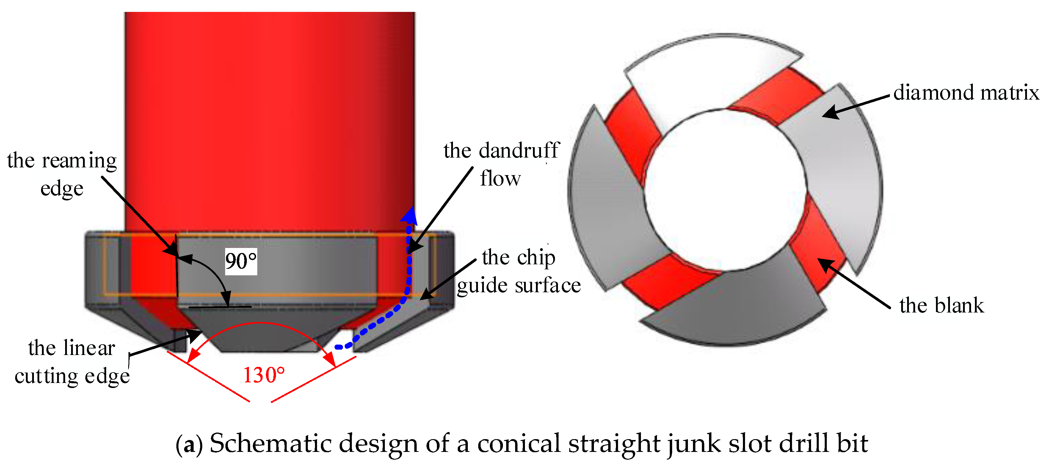
This paper introduces two design schemes for the drilling bit: the conical straight junk slot and the conical spiral junk slot, as illustrated in
Figure 2. Its key parameters and structure schematic drawing are detailed in
Table 2. The functions of each part are described as follows:
- (1)
Chip guide surface: This surface is employed to expel the cuttings and dissipate the heat generated while drilling Martian rocks along the drill pipe through the cuttings junk slot. This ensures optimal drilling performance for the string.
- (2)
Diamond matrix: This component embeds diamond abrasive grains. The matrix undergoes constant wear and tear to expose new diamond grains, thereby achieving self-sharpening and maintaining stable cutting performance for the drilling string.
- (3)
Grinding edge: By increasing the vertical force, the diamond grains undergo extrusion fracture against the drilled object. The resulting material debris is then discharged along the junk slot, achieving the purpose of grinding.
- (4)
Blank: This part supports the diamond matrix and contributes vertical force to the linear cutting edge.
The two configurations are described in detail as follows:
- (1)
Conical straight junk slot drills
The conical straight junk slot drill comprises a conical base and four inlays spaced at 90° intervals. Notably, the conical blank configuration facilitates drilling centering. The linear cutting edge is tasked with grinding into the Martian rocks and rock objects at the hole’s bottom, inducing shear failure. Meanwhile, the reaming edge is responsible for the secondary grinding of the hole wall. The combination of the chip guide surface and the conical surface of the blank forms a cuttings channel, facilitating the transfer of the cuttings to the back end of the drill pipe’s spiral groove. The helical feed principle is further employed to transport abrasive cuttings outside the drill hole.
- (2)
Conical spiral junk slot drills
The conical continuous spiral edge drill comprises a conical blank and four sets of diamond matrix with four slices distributed at 90°. The four sets of curved cutting edges function to grind Martian rocks simultaneously, and the cutting principle closely resembles that of the straight junk slot drill.
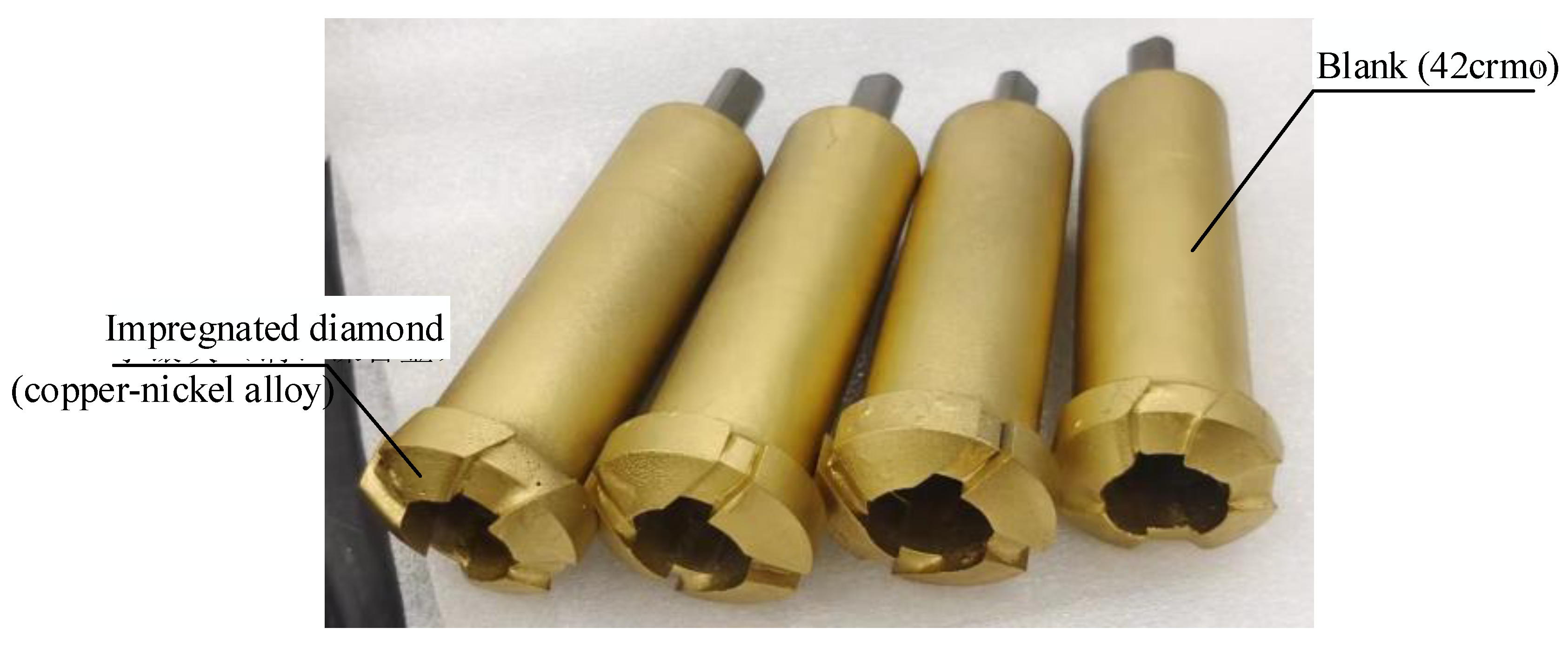
3.2. Design of Impregnated Diamond Grinding Tools
3.2.1. Conception of Diamonds and Selection of Matrix
The task target of this drilling string is a hard and strongly abrasive rock formation; in order to meet the design requirements of the drill bit, the diamond should have self-sharpening properties, hardness, and impact resistance, and the matrix should have high abrasion resistance, high flexural strength, and good impact resistance. Therefore, we chose the size of 0.5 mm–0.7 mm, a concentration of 100%, the strength of 18,000–22,000 kgf/cm2 high-quality artificial diamond, and 210 HV hardness; in addition, a good heat-resistant copper–nickel alloy was chosen as the drilling string matrix material.
3.2.2. Selection of the Amount and Distribution of Diamond Inserted Edges
- (1)
Blades
The effect of exit height on drilling performance can be expressed by the following equation:
where
V is the mechanical drilling speed (m/h), h is the diamond exit height (μm), a and b are the hyper-parameters.
The diameter of diamond grains in impregnated diamond bits typically ranges from 0.1 mm to 0.5 mm. The protruding amount of diamond from the impregnated diamond bits is restricted to 10% of the grain diameter for hard rock. Furthermore, the compression depth into the rock is limited to less than 2/3 of the protruding edge amount, which is greater than 0.02 mm.
Assuming that the diamond particles are spherical with a diameter of
d (mm), the number of diamond particles in the 1 cm
3 working layer is as follows:
where
N is the number of diamond particles in the 1 cm
3 working layer (pcs),
c is the diamond concentration (400% system),
d is the average diameter of diamond (mm) [
31].
Calculation gives N = 81,870 pcs.
- (3)
Rock-breaking efficiency
In the case of hard and weakly abrasive strata, the rock powder produced is fine, resulting in minimal abrasion of the diamond bit. Therefore, while maintaining a specified amount of cutting edge, employing a larger grain size of diamond can enhance the cutting force exerted on the strata. This allows the diamond to penetrate the rock layer more effectively, reducing the risk of profiling and improving rock-breaking efficiency.
The rock-breaking efficiency is derived by calculating the volume of diamond participating in the cutting on the 1 cm
2 profile face as follows:
where
Vcut is 1 cm
2 volume of the diamond participating in cutting on the profile surface (mm
3);
V is 1 cm
3 volume of the diamond contained in the matrix (mm
3);
c is the diamond concentration (400% system); k is the diamond out coefficient.
The calculation gives Vcut ≈ 0.57 mm3.
- (4)
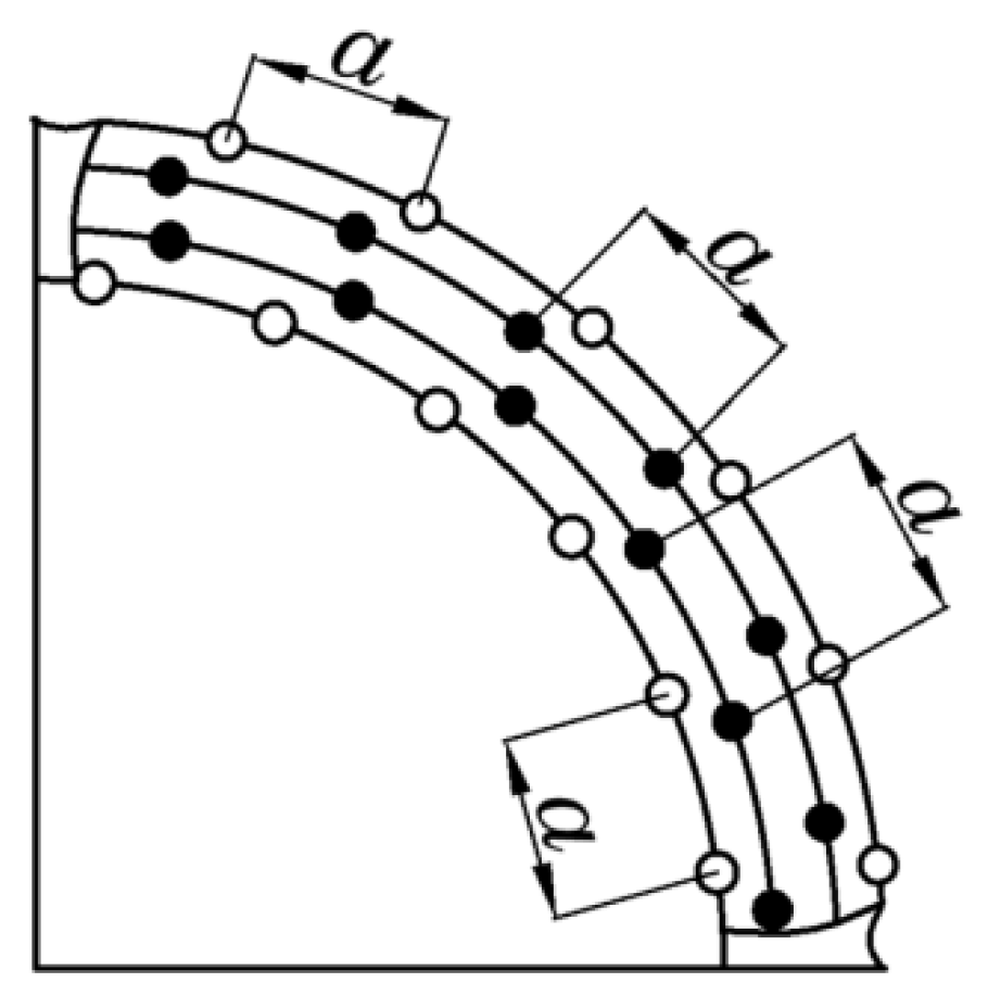
Abrasive grain arrangement
The diamond grains are organized in an equidistant arrangement, as illustrated in
Figure 3. This configuration ensures the smooth self-sharpening of the edge, reduces the cost of raw materials, and enhances the lifespan and efficiency of the string. The diamond’s average particle size is 0.18 mm, and the longitudinal spacing between the upper and lower two layers of the diamond is set at 0.22 mm, with a matrix layer thickness of 0.04 mm between the two diamond layers.
In summary, the parameters related to the impregnated inserts are shown in
Table 3.
3.3. Design of Drill Base Conical Angle and Chip Removal Groove
3.3.1. Design of Drill Structure and Junk Slot Configuration
Drilling on Earth, the cuttings could be effectively removed, minimizing temperature rise by employing drilling fluid. However, when conducting sampling on Mars, the dry drilling method is employed. Firstly, to avoid contaminating the Martian environment; secondly, the presence of external liquids is not permissible due to the stringent conditions of outer space. In the dry drilling method, the cuttings are discharged outside the drilling hole through the chip removal groove in conjunction with the drilling gauge, creating space for the drill teeth of the drilling string. The cuttings serve the dual purpose of providing room for the drill teeth and carrying away the heat generated during drilling.
Considering the characteristics of the target drilling object, the internal conical angle configuration of the junk slot has the potential to direct the cuttings and rock particles toward the core, thereby impacting the drilling process. Conversely, insufficient junk slots may compromise drilling efficiency and increase drilling resistance. On the other hand, an excessive number of junk slots can elevate the overall temperature of the drill bit during drilling. Given these considerations, a balanced approach is adopted by selecting four straight and spiral junk slots.
Based on the research conducted by Zhang Weiwei [
32] at Harbin Institute of Technology,
Figure 4 illustrates that an increased spiral lift angle correlates with more excellent drilling resistance. Conversely, a tiny lift angle can result in a thin chip edge, making it susceptible to chipping. To strike a balance and align with the requirements of the machining process, a spiral lift angle of 60° is chosen in the design.
When selecting the drill bit blank, the conical drill bit is favored as it sacrifices bit size to enhance the vertical turning structure of the cuttings channel on the planar blank drill bit. This choice aligns more closely with the hydrodynamic requirements of chip flow, entails lower structural complexity, and is supported by prior simulations of Zhang Weiwei’s planar and conical drills. Notably, the simulations reveal the suboptimal cuttings evacuation effect of planar drills. Considering cuttings removal efficacy and overall drilling performance, a conical blank is chosen for the drill bit. ESA’s Exomars series has successfully employed a shallow conical blank with a linear cuttings removal wing structure, demonstrating commendable drilling performance.
3.3.2. Drill Bit Conical Angle and Matrix Design
- (1)
Conical angle design
Analyzing the drill bit’s top angle size based on the rock hardness, considering that the predominant rock type is dense basalt, with main components including feldspar, pyroxene, and olivine. The hardness of these constituent basaltic rocks ranges from 5 to 7, slightly higher than the common steel used in testing with a hardness of 5 to 6. As the hardness of the drill bit decreases, a larger top angle is recommended. Therefore, the top angle is selected within the range of 125° to 130°. A smaller top angle results in increased radial force on the drill bit, potentially causing the dislocation and fracture of the diamond matrix in the impregnated diamond bit under this force. To maintain stability while accommodating the hardness considerations, a top angle of 130° was chosen.
At the same time, in order to prevent the formation of rock ridges during drilling and to ensure drilling efficiency, the diamond abrasive grains are arranged equidistantly, and the longitudinal spacing between the upper and lower two layers of the diamond should be 0.22 mm (the average grain size of the diamond is 0.18 mm), and the thickness of the matrix layer between the two layers of the diamond is 0.04 mm.
The cuttings removal process from the drill bit can be categorized into two methods for grinding the drill-grinding block on the drilling sample, as illustrated in
Figure 5.
Where φ is the anterior angle of the matrix; α is the tire-grinding angle; γ is the posterior angle of the matrix.
The research conducted by Ding Yanhao [
33] from Harbin Institute of Technology indicates that the load on the drill bit diminishes with an increasing back angle of the matrix. However, beyond a matrix rear angle exceeding 12°, the reduction in the drill bit load becomes less pronounced. Furthermore, decreasing the matrix rear angle tends to compromise the strength of the cutting edge, leading to damage forms such as crushing and wear. Consequently, guided by the outcomes of single-junk slot cutting tests documented in the literature, the matrix back angle was designated to be 17°.
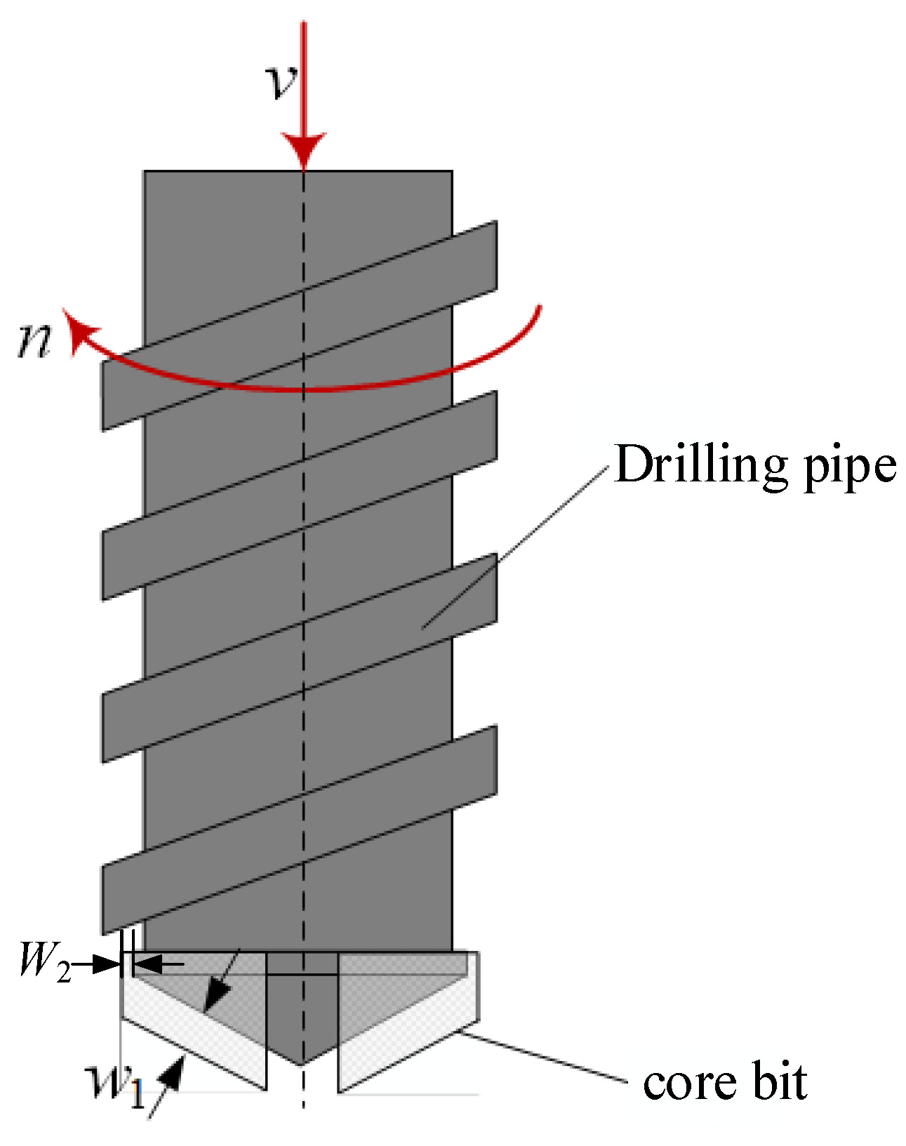
3.3.3. Design of the Height of the Cutting Edge in Each Direction of the Drill Bit
Figure 6 illustrates the schematic diagram of the height of the bottom exit edge (
w1) and the height of the exit edge (
w2), where
v represents the feed speed,
n denotes the rotational speed,
w1 is the length of the bottom exit edge, and w
2 is the height of the exit edge. During the actual drilling process, the front surface of the grinding edge accumulates debris from Martian rocks, accompanied by the volume expansion of Martian rock cuttings. Taking into account the Martian rock expansion coefficient (K
p), the number of grinding edge inlays (
N), and the median particle size of Martian rocks particles (
Dp), it is crucial that the height of the bottom exit edge surpasses the single-edged depth of the cut (
ht). Additionally, the height of the exit edge for Martian rock particles should be three to five times the median particle size. The following formula can express this requirement:
Considering challenging working conditions characterized by low rotational speed and high feed rate, taking the rotational speed
n = 50 r/min, feed rate
v = 300 mm/min, expansion coefficient
Kp = 1.4, the median particle size of the Martian rock particles
Dp = 0.5 mm, and the number of grinding block inlays
N = 3, the calculation for the bottom exit edge height
w1 and exit edge height
w2 can be determined within a given range. This calculation considers the following equation:
The final preferred bottom out edge height w1 is 3 mm and the outer edge height w2 is 2 mm.
In the process of drilling, the biggest influence on the drill bit is the size of the drilling particle for the edge height < r < base radius of the drill bit. Hence, the critical particle size range is 3 mm to 16 mm. Since the drilling of rocks generates larger debris, mainly falling within the particle size range of 1 mm to 5 mm, and these debris particles introduce significant resistance to the diamond drill bit during the grinding process, increasing the bottom exit edge height is imperative. By choosing a height coefficient for the exit edge of 2, the calculated height of the bottom exit edge becomes 6 mm.
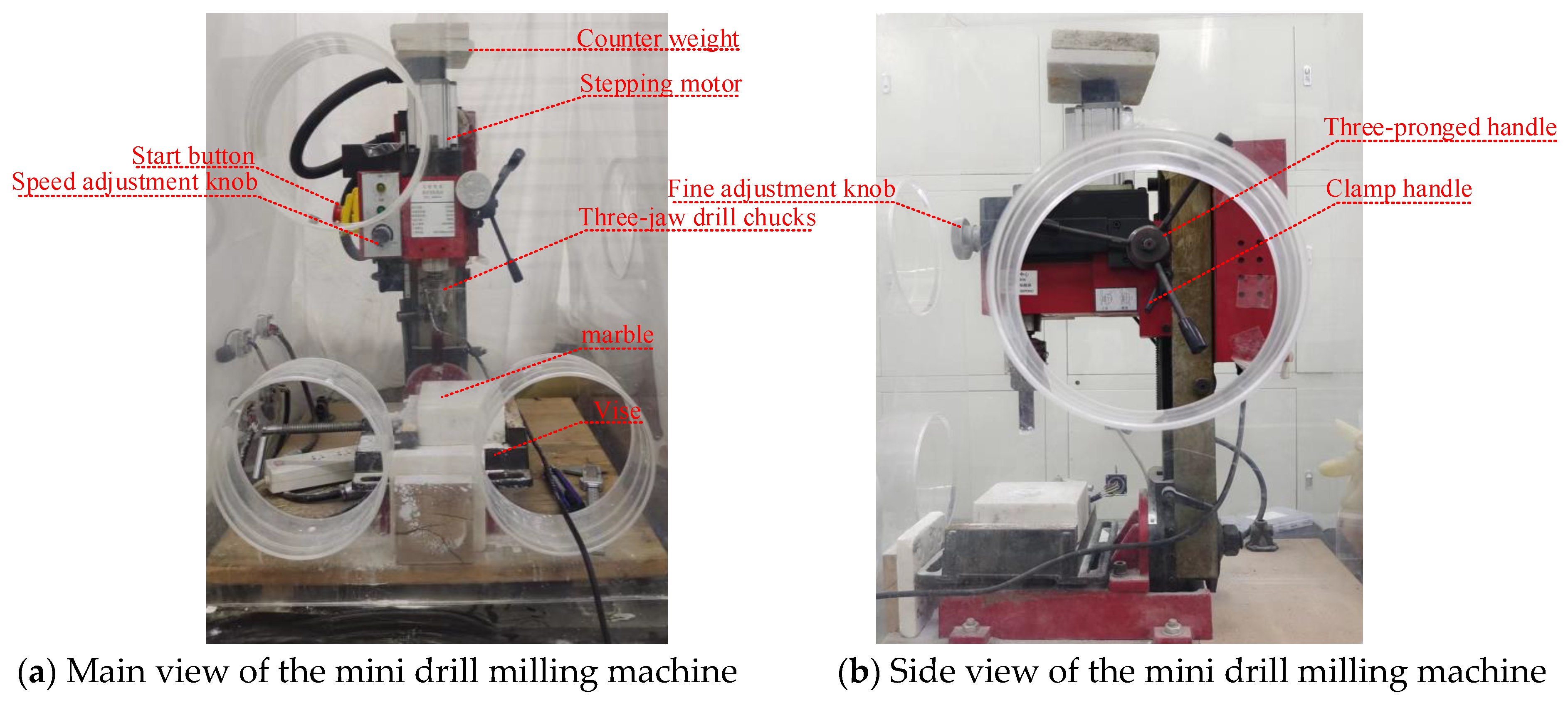
5. Simulation Analysis of Heat Generation during Drilling
To model the temperature elevation of the drill bit throughout the drilling operation, finite element simulation software was employed to simulate the temperature increase of both the sample and the drilling string during the drilling stage. The computation of the power generated by the drill bit during the drilling process was conducted by the equation presented below:
where
P is the power (W),
n is the rotary speed (rpm),
K is the correction factor (dimensionless),
I is the flow rate (m
3/s).
Here, the correction factor of the motor is assumed to be 0.28, with a motor current of 2.3 A. At a rotary speed of 2000 rpm, considering energy conversion losses during the drilling process, typically set at 10%, the estimated power on the drill bit is approximately 121.4 W. During the simulation process, it was assumed that this portion of the energy was entirely transformed into heat at the front end of the drill bit.
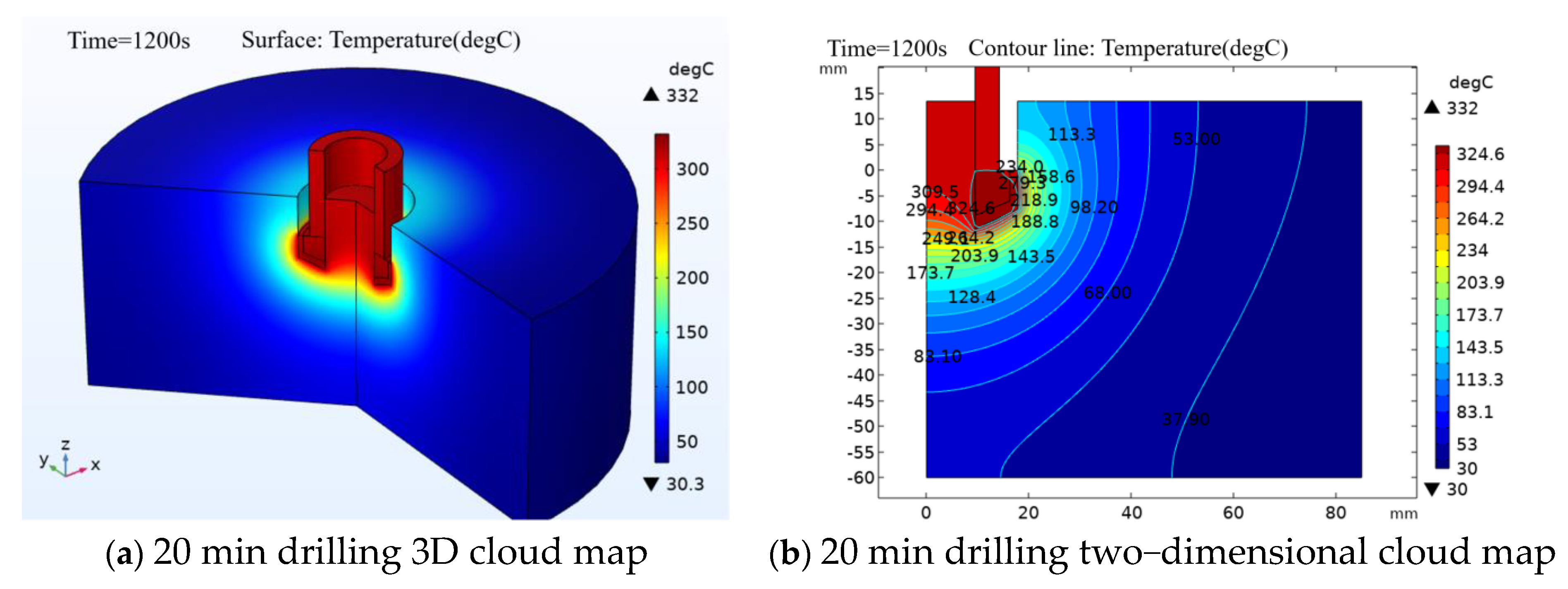
Figure 19 illustrates a thermal map showing the temperature distribution around the drill bit; the ambient temperature is 22 °C, and the map focuses on the basalt after 20 min of drilling. The visualization reveals a distinct thermally affected zone within the sample during drilling. Notably, the central portion of the sample in direct contact with the drill bit exhibits the most pronounced temperature perturbation. Furthermore, the overall temperature of the drill bit increases, with the most significant rise occurring at the drill edge, reaching up to 327 °C.
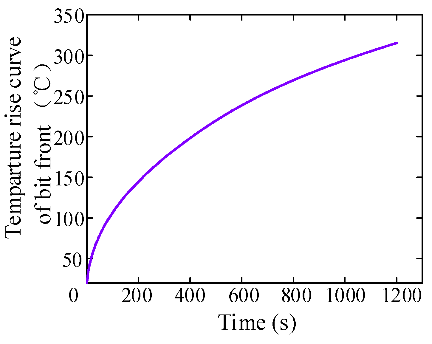
By adding a probe to the front part of the drill bit, in direct contact with the sample, the arrangement is similar to what is shown in
Figure 20.
Figure 20 illustrates a clear trend of increasing the temperature of the drill bit over time during the drilling process. After 20 min, the temperature peaks at 327 °C and is expected to further rise with continued drilling. This observation underscores the substantial heat generation and temperature rise of the sample, providing valuable insights into its heat generation characteristics. Such findings are pivotal for enhancing control over drilling temperature in future studies.
6. Conclusions
In this study, two types of impregnated diamond drill bits were specifically designed to address the prevalent issue of significant wear in Mars rock coring drill bits and the susceptibility of samples to heat denaturation. The tests were structured to analyze the drilling speed, abrasion resistance, drilling force under load, and temperature rise of the samples. The goal was to comprehensively investigate the drilling efficiency and feasibility of Mars rock sampling. The following conclusions were drawn:
- (1)
By analyzing the basic mechanical properties of Martian rocks, conical straight junk slot- and spiral junk slot-impregnated diamond drill bits were designed, both using a 130° drill base conical angle with a 17° back angle of the grinding edge. The difference between the two configurations is the front angle of the grinding edge and the height of the cutting edge.
- (2)
Through the comparison test, it can be seen that when the rotational speed is 800 rpm and the drilling time is 20 min, the spiral drill bit is 16.6 mm deeper than the straight drill bit, and the spiral drill bit performs better than the straight drill bit in terms of drilling rate.
- (3)
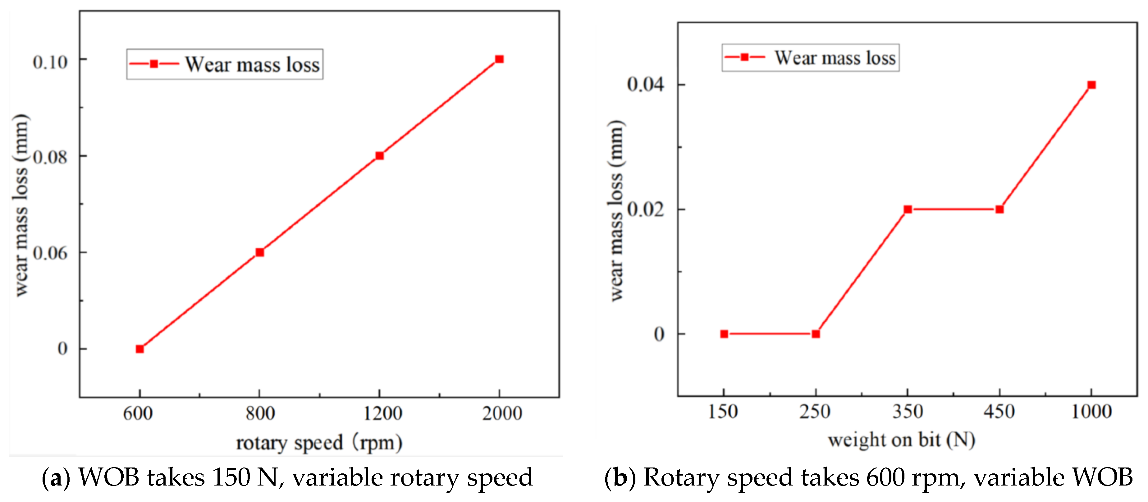
An obvious increase in wear is observed with higher drilling pressure and increased bit speed, with the spiral drill bits exhibiting less wear compared to the straight drill bits.
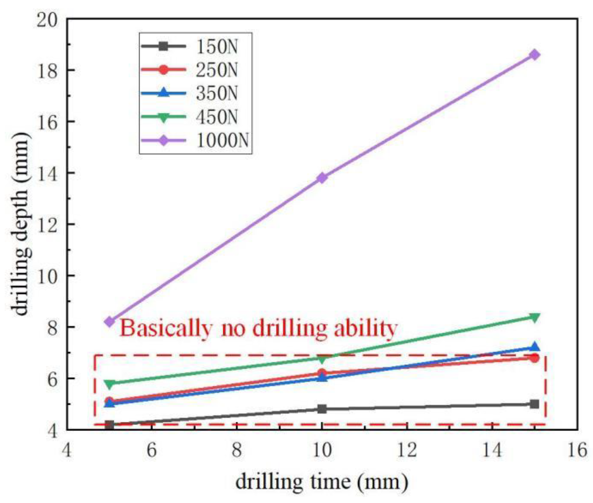
- (4)
With an increase in drilling pressure, the drilling performance of the drill bit significantly improves. Below 450 N, the drill bit exhibits minimal drilling ability, with the maximum drilling ability observed under the test conditions of 1000 N in this study.
- (5)
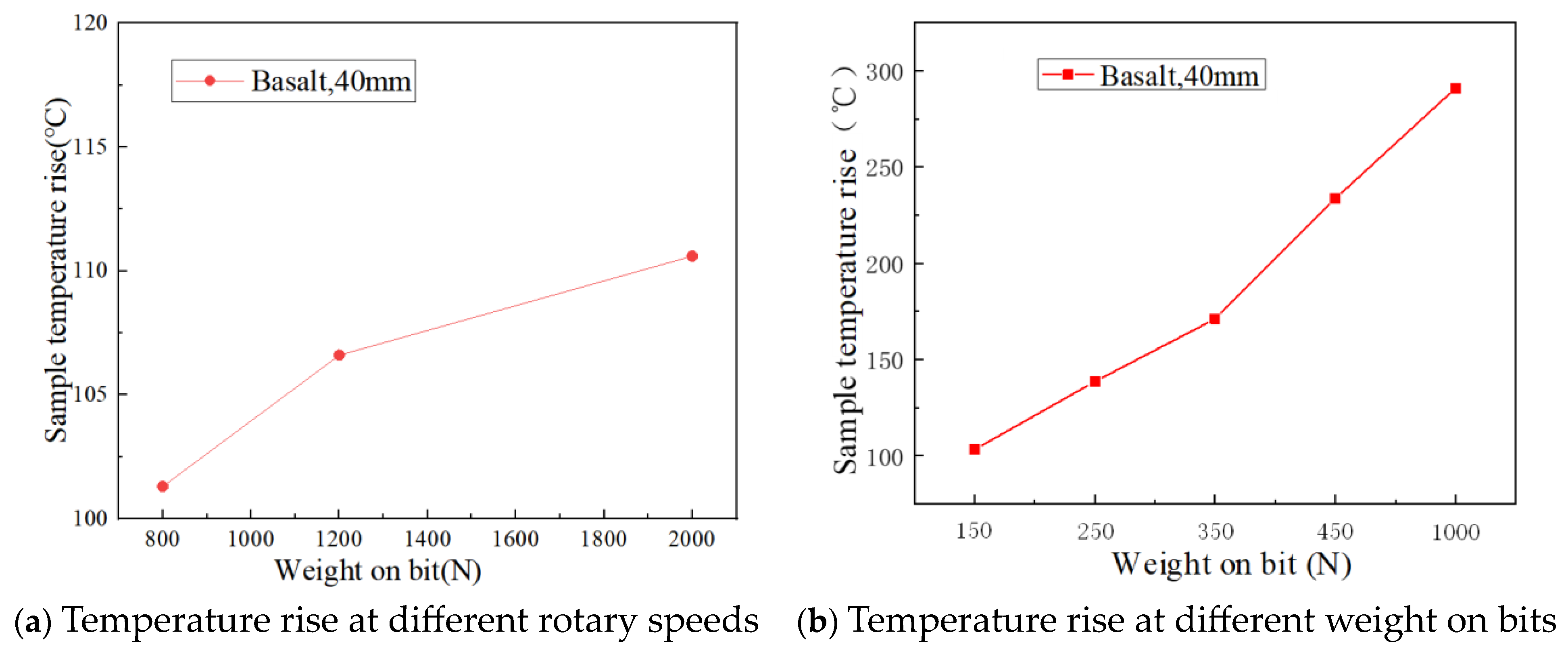
When other drilling conditions remain unchanged, the drilling temperature rise increases with the increase in drilling pressure. Under the test conditions in this study, the drilling temperature rise reaches a maximum of 290.9 °C at a drilling pressure of 1000 N.
Compared to previous Mars drilling tools, inlaid diamond bits exhibit excellent self-sharpening properties. This is attributed to the use of inlaid diamond material and factors such as a large thermal conductivity area, resulting in prolonged service life due to enhanced thermal conductivity. However, the inlaid diamond drill requires high drilling speeds, leading to significant heat generation during operation. Additionally, processing the intricate configuration of inlaid diamond material is challenging and costly, constraining design possibilities for the drill.
The drilling tool designed in this study primarily focuses on enhancing the drilling efficiency, penetration capability, and adaptability to various operating conditions for extracting high-hardness Martian rocks. However, due to the limitations in experimental conditions, it was not feasible to simulate the actual Martian environment. Nevertheless, this study explored the temperature variation trends of the spiral drill head under different drilling speeds and pressures, offering insights for future research. In subsequent studies, we intend to consider the construction of Martian environmental conditions and incorporate temperature and atmospheric parameters for further investigation.


 ,
, 


