Abstract
The electric urban air mobility sector has gained significant attraction in public debates, particularly with the proliferation of announcements demonstrating new aerial vehicles and the infrastructure that goes with them. In this context, the development of new methodologies for the design and sizing of actuation systems, ensuring high performances of these aerial vehicles, remains an important task in this process. This will allow for better integration within this transport sector. In this paper, a robust design optimisation approach of multiphase fault-tolerant (FT) outer rotor (OR) permanent magnets (PM) for multirotor aerial vehicle applications is proposed. In order to show the effectiveness and the robustness of the proposed design methodology, the number of stator winding phases, with a fractional slot concentrated winding (FSCW) configuration, as well as the PM configuration are considered as variables. Thus, four cases for the number of phases are considered, namely 3, 5, 6 and 7 phases, where for each number of phases case, the PM takes 3 configurations, namely surface PM, interior V-shape PM and interior spoke PM. First, a pre-sizing step is carried out, consisting of selecting the optimal combinations slot/pole, designing the multiphase FSCW layout, and estimating the electric motor (EM) geometry using analytical computations to obtain a preliminary validation of the design specifications. Second, constrained multiobjective optimisation is considered in order to optimise the EM performances, such as motor efficiency and weight, under constraints where the FEMM/Matlab based Finite Element Analysis (FEA) tool is used to perform this optimisation. Finally, results analysis and performance comparisons of different EM configurations are carried out in order to assess the design parameters, such as phases number, PM position, and harmonic currents in the EM design and consequently to select the best configuration for the considered application.
1. Introduction
Through the use of fully electric or hybrid propulsion systems, vertical take-off and landing (eVTOL) aerial vehicle technologies represent a good solution to transport cargo or a small number of passengers from point to point in highly congested cities and areas. This will help avoid traffic and provide a more ecological means of transportation. Their capabilities to hover and to perform VTOL, as well as their great maneuverability, make multirotor eVTOL technologies an excellent choice for the urban air mobility (UAM) market [1,2]. However, with the rapid evolution of transport market requirements, especially in terms of efficiency, performance, safety, and large endurance, the development of new, precise, and rapid approaches to the design and optimisation of these aerial vehicles remains an important task in this process of integration. Electric motors (EMs) play a fundamental role in enhancing the performances and safety of the electric propulsion systems, and thus upgrading the performances and safety of all aerial vehicle [2].
As reported in [3], EMs for electric, more-electric or hybrid aircraft and airspace applications, are defined by their major requirements (MR), namely weight, which is a very important indicator that directly affects the overall performance of the vehicle; volume, which is linked to the limited volume reserved for the motorization; safety, which directly affects the mission success, performance, and dispatchability; efficiency, which also becomes an MR for energy saving and performance and finally the cost, which indicates the accessibility of a new solution. According to this same reference and to [4,5] PM synchronous motors remain the best choice to achieve these MR, in comparison with induction motors, switched reluctance motors, synchronous reluctance motors, and wound field synchronous motors. This is principally explained by the high torque and power density, low rotor and stator losses and the high-speed capability that the PM motor could offer.
Multiphase motors with a number of phases higher then 3, in comparison with conventional three-phase ones, can improve power density and fault tolerance due to the redundant design, reducing the cost of circuit isolation by reducing the DC bus voltage, offering more degree of freedom for design and control [6,7,8]. These intrinsic characteristics make multiphase motors a suitable solution for eVTOL aerial vehicle applications, where reliability and safety as well as performance are highly required.
Multiphase PM fault tolerant motors for electric and more-electric aircraft and airspace applications are researched in [7,9,10,11,12,13,14,15,16], where the different phase numbers 5-phase, 6-phase, 9-phase, and 15-phase are commonly considered. In [10], authors propose multi-3-phase PM motors in order to enhance the weight as well as the fault tolerance of an electromechanical actuator (EMA) for helicopter primary flight control. A 5-phase concentrated winding PM motor was proposed for the electric steering of a commercial aircraft nose landing gear in [12]. A differential evolution (DE) optimisation technique was used in order to minimize the weight with respect to torque and efficiency targets. Authors in [14] have proposed a 6-phase PM motor for helicopter tail rotor applications, where an outer rotor with two interior PM configurations, spoke configurations and a V-shape configuration are designed, and their respective performances are compared in order to select the suitable configuration.
State of art regarding EM for eVTOLs applications are reported in [17,18,19,20], where the power and torque densities constraints are considered. NASA in [17] aims to present a design optimisation approach of 3-phase PM motors with an efficiency constraint higher than , and a power density of 13 kw/kg for eVTOLs applications. The motor design is based on the genetic optimisation of the motor fitness function, which is defined using specific power, mission efficiency, peak winding temperature, and the thermochemical aging of the winding insulation over 10,000 missions. The performances are presented and discussed. Authors in [20] propose a 9-phase PM motor with a fractional slot concentrated winding (FSCW) configuration. The static performances of the motor, namely the torque and the torque ripple, the efficiency, and losses are presented and discussed.
However, these multiphase EM motors cited in these papers are unique cases, where the influence of increasing the phase number is not evaluated in combination with the PM configurations that they could take. Additionally, the multiphase winding configuration favors the appearance of higher odd harmonics in the EMF waveform, which leads to improving the static performance as well as the FT capabilities of the EM. Nevertheless, a methodology to extract the main harmonics of the current, with their corresponding optimal ratio, is necessary to reach these goals and to avoid the torque ripple increasing.
In this paper, a robust design optimisation approach for direct drive multiphase PM OR motors is presented and formulated. The motor, through direct coupling with the propeller, ensures the propulsion of a fixed-pitch multirotor aerial vehicle. Through the matching of the advantages of multiphase motors, FSCW configuration, and the consideration of harmonics higher than the fundamental in the injected control currents, the performances and reliability of the motor are improved, where a multiobjective optimisation is carried out using the motor efficiency and the motor active components mass as the objective function. This article takes four different configurations of the number of phases and slot/pole () combinations, namely 3-phase 44/48 , 5-phase 40/44 , 6-phase 40/48 , and 7-phase 48/56 . The consideration of high pole number with FSCW allows to improve the motor performances and to reduce the motor mass. For each configuration, 3 PM positions are chosen, which are surface PM, Spoke PM, and V-shape PM. Through these different configurations, a performance analysis and comparative study are carried out to assess the effect of each parameter on the performances of the EM.
This article is organised as follows, Section 2 provides details about the design requirements and characteristics of the multiphase actuator. The design methodology as well as the basic structural and analytical pre-sizing step is presented in Section 3. Section 4 is devoted to the formulation of the optimisation problem; Section 5 analyses and compares the performances of each configuration in order to select the suitable configuration. Conclusions and perspectives about the work are presented in Section 6.
2. Design Requirements
The application context of this motor is the propulsion of a multirotor aerial vehicle, with a gross take-off weight of 450 kg (). This aerial vehicle is composed of 6 propulsion chains (), including a propeller, EM, electronic speed controller (ESC), and energy storage system (ESS) that could feed several propulsion chains. Moreover, this vehicle could carry a payload of of the (roughly 100 kg), with a maximum cruising speed of 54 km/h at altitude h of 500 m. For a multirotor aerial vehicle, the power flight mission, as illustrated in Figure 1, is divided into 3 phases of take-off/hovering, cruise, and landing/hovering. Among these phases, it is remarkable that the power required during the take-off and landing phases is much higher than during the cruise phase.
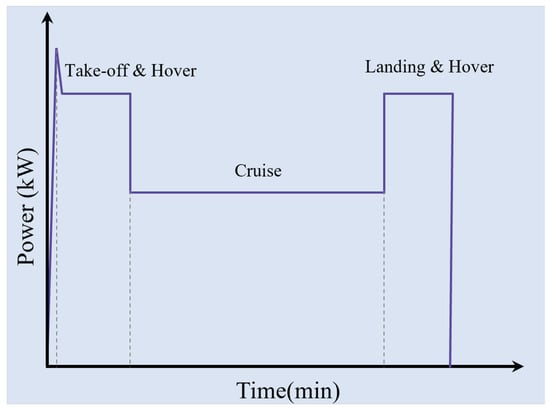
Figure 1.
Typical power flight mission of a multirotor aerial vehicle.
During the take-off and landing, the required force for the lift (N) is given by:
where a (m/s2), g (m/s2) and (N) are, respectively, the vehicle acceleration, the gravitational acceleration and the drag force which is a function dependent on the vehicle speed and geometry.
The acceleration of the aerial vehicle is fixed as ). In order to take into account the drag force and motor efficiency, which is supposed to be a small drag profile, an efficiency is considered. Thus, the motor power (kW), during the take-off and the landing segment flight operation, must satisfy:
During the cruise flight mission, the thrust is equal to the drag force. In this case, the lift force is given by , and motor power must satisfy 13 kW, with a thrust to weight ratio of .
Regarding the propeller sizing in order to satisfy the mission power flight, a two blade fixed pitch carbon fiber-based material is chosen. This category of propellers is characterized by its stiffness and lightweight. The propeller parameters are the diameter , the blade number and the pitch angle or the pitch which is related to the pitch angle by and its model, which describes the propeller thrust (N) and torque (N · m) in terms of the other parameters given by [21,22,23]:
where (kg/m3), , , and N (rpm) are, respectively, air density, thrust coefficient, torque coefficient, and propeller velocity. The air density, , is determined by both the local temperature (°C) and the air pressure p, which is further determined by altitude h (m). The thrust and torque coefficients are dependent on the propeller blade airfoil shape. Their model and their approximative values are presented in [21]. Based on the sizing methodology presented in [21], it is suggested that with a carbon fiber propeller of m and m, the developed thrust is 74 kg at a velocity of 3300 rpm. The propeller parameters and its thrust and torque in terms of the velocity are, respectively, given by Table 1 and Figure 2. It is noticeable, as shown in Figure 2, that the working motor torque is 36 N · m.

Table 1.
Specifications of multirotor aerial vehicle propulsion chain.
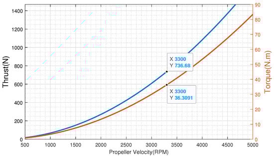
Figure 2.
Characteristics of the designed propeller.
3. Design Methodology and Elements for Optimal Design
3.1. Design Methodology
The design optimisation method presented in this paper is based on a combination of analytical and numerical optimisations design methods for OR multiphase PM electric actuators. As shown in Figure 3, this methodology offers the possibility of considering several topologies in terms of motor number of phases , the combinations, winding configuration, and positions of PM. This approach takes as input the rated range speed with the maximum torque , which is defined through the AV flight mission, the rated bus dc voltage , and constraints in terms of embedded mass and maximum volume reserved for the actuator (). It should be noted that in aircraft and airspace applications such as the one considered in this paper, the constraints in terms of mass and volume are critical and directly influence the AV performances.
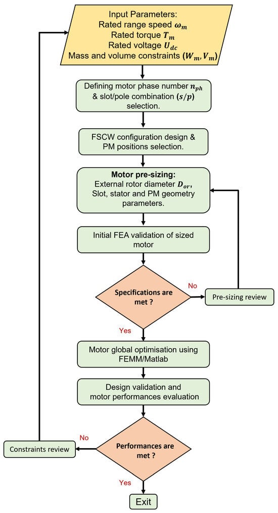
Figure 3.
Design methodology flowchart.
In summary, this methodology is resumed in three main steps. The first step, which includes the number of phases selection and FSCW design, consists of performing choices for the electric motor optimal design. The number of phases selection is subjective to the application constraints, especially in terms of the power level of the application as well as the number of open-circuit (OC) phases that the EM could tolerate. In this paper, 4 number EM phase cases are considered, which are the 3, 5, 6, and 7 phases. This will allow us to assess its effect on the EM electric and magnetic performances. The configuration design is based on the combination selection. The Section 3.2 and Section 3.3 give respective details for an optimal selection of the combination and design of the corresponding winding layout.
The second step of this approach, which is presented in Section 3.4 and Section 3.5, is devoted to the EM pre-sizing, including PM position selection, and analytical sizing. The analytical sizing is based on empirical parameters, namely the quantity of torque per rotor volume () and the shape ratio (). This step allows the validation of the initial specifications input of the approach, especially the motor output torque, using finite element analysis () validation, in addition, it makes it possible to limit the search space of the optimisation algorithm, which leads to reducing the calculation time.
The final step consists of carrying out a global multi-objective optimisation of the EM based on the Direct algorithm as explained in Section 4.2. This optimisation consists of both maximizing and minimizing, respectively, the EM efficiency and the EM weight (kg)) in a single function with the use of weighting coefficients. Constraints on the electromagnetic torque , on the flux density , and on the electromotive force are considered in the optimisation problem as shown in Section 4.1. In the case of multiphase motor configuration, it is possible to consider the injection of currents containing higher harmonics than the fundamental, which results in a compact EM structure with a high torque density. Thus, in this paper, the formulation of the optimisation problem considers two scenarios, a scenario of optimisation with the injection of purely sinus currents and a scenario of optimisation with non-sinus of currents. A new methodology for selecting the optimal current harmonics ratio that allows the creation of torque without the pulsation effect is developed and presented in Section 4.3. The design methodology is enclosed by the analysis and comparison of the EM magnetic and electrical performances.
3.2. Selection fo the Combination
The optimal selection of s/p combinations depends on several parameters such as winding factor, torque density, torque cogging, motor efficiency, rotor losses, and noise level [24,25,26]. In the multiphase concentrated winding, the combinations that allow the realisation of balanced winding should fulfil the following condition [27]:
where is the number of slots, p is the number of pair poles, number of EM phases, k is an integer number, and is the great common divisor. The torque cogging and noise level are directly conditioned by the (least common divisor) and of the combination. The larger the value of , the smaller the value of the torque cogging, and the larger the value of the , the smaller the level of noise and the vibration. Furthermore, regarding the integer k, which is also called the key winding factor in [27], the higher it is, the more the magneto-motive force (MMF) distribution would contain lower amplitude of higher harmonics which leads to lower torque ripper. The winding factor is also used as an indicator for the combination selection, where the larger it is, the torque density and the efficiency of the motor are improved [25,26]. In this paper, the following combination is selected for each phase number: 3-phase , 5-phase , 6-phase and 7-phase .
Table 2 gives the , , k, and , including the third() harmonic for the 5-phase and 6-phase machines and the third and fifth() harmonic for the 7-phase machine for each combination.
Table 2.
Characteristics of the combination for each phases number.
3.3. Winding Configuration Design
Multiphase fractional slot concentrated winding (FSCW) configuration has gained much attention in the field of electric motors, particularly for aeronautical applications. This interest could be explained by the multiple advantages that present this type of winding configuration, in particular, in terms of a high motor torque density, improvement of the motor efficiency by reducing copper losses, improving the fault tolerance by reducing the coupling between phases, and ease of manufacturing and installation [28,29,30]. However, this kind of winding layout leads to a significant appearance of subharmonics and higher harmonics in the MMF distribution, which could be limited, as explained in the Section 3.1, by an appropriate selection of the combination. There are two main types of FSCW, namely single-layer (SL) winding and double-layer (DL) winding. SL winding configurations have stator slots that are each occupied by the coil sides of a single stator phase, while each slot in a DL winding configuration is split equally between coil sides from two phases. In this paper, the DL configuration is considered for the FSCW configuration design.
Regarding the optimal winding layout, it is based on the and methodology presented in [31], which was applied to a 3-phase PM Machine with an FSCW. In this paper, this methodology is extended to a number of phases greater than 3. The first step is to reduce the number of slots per pole per phase () to a fraction of two prime integers x and y, where:
A repeatable sequence of 0 and 1 specific to the winding can be derived from this relation. It is a list of y numbers which characterizes the winding distribution under poles. The structure of the whole winding can be derived from a periodic distribution of the structure under y poles described by consecutive repeatable sequences if y is an even number. If y is an odd number, this distribution is antiperiodic. The number of 1 in the sequence is equal to y, and the number of 0 sequences is equal to .
As an example, in the case of 5-phase with the combination of :
the following steps explain how the whole winding layout is obtained:
- Step 1: The initial repeatable sequence is: 11000000000;
- Step 2: The optimal repeatable sequence is: 10000010000;
- Step 3: The usual phase sequence is associated with the hole sequence. In the case of 5-phase, given by: ( characterizes the return conductor corresponding to coil of phase A);
- Step 4: The conductors associated with the numbers 1 of the sequence are selected to make the first layer of winding. This allows to obtain the first layer winding. The second layer winding is obtained by reproducing and shifting the initial layer by a tooth or a slot width. Figure 4 gives the winding layout for a quarter of the machines (). The whole winding configuration is completed by an antiperiodic symmetry, as is an odd number in this case.
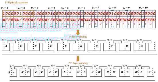 Figure 4. Optimal winding layout for a quarter of the 5-phase .
The same process is applied to other configurations, namely 3-phase , 6-phase , and 7-phase . Figure 5a–d gives their whole winding configuration, respectively.
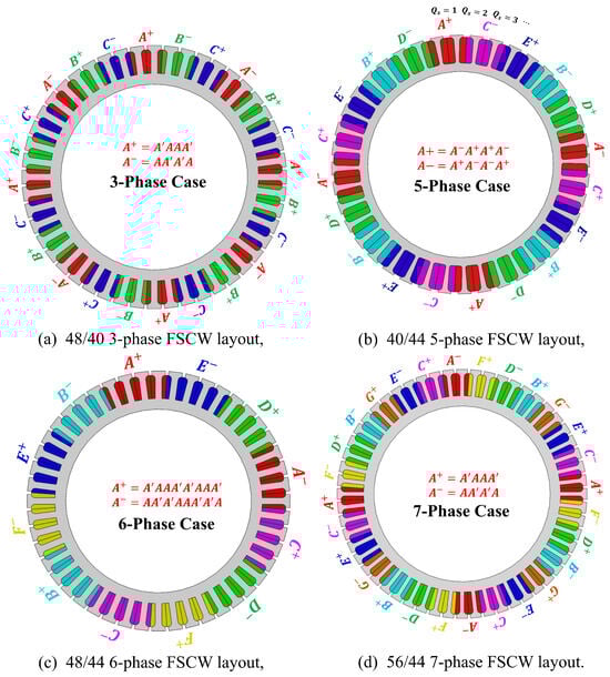
Figure 5.
Winding layout for different cases.
3.4. PM Configurations
There are many configurations for installing magnets on or in the rotor. These topologies can be divided into two main categories: surface magnet (SPM) rotor and interior magnet rotor (IPM). In comparison with other topologies, the SPM rotor configuration is widely adopted as an efficient solution, due to its simple structure, and ease of manufacture; the absence of magnetic salience and reduced tooth effect minimizes torque oscillation and makes control much easier [32,33]. In the case of the IPM rotor, the magnets are inserted in the rotor, which makes them intrinsically well protected mechanically and magnetically [32,33]. Figure 6 provides the 3 PM configurations which will be considered in this paper. It is noticeable that the consideration of several PM configurations will allow us to assess their influence on EM performances, especially the motor efficiency, torque density and torque rippling.
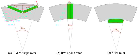
Figure 6.
PM configurations.
3.5. Analytical Pre-Sizing
The analytical pre-sizing stage allows an initial validation of the specifications, particularly in relation to the maximum torque that the EM must provide. This step also makes it possible to limit the search space that the optimization algorithm must consider to locate the actuator optimal geometry. The analytical sizing of the EM is determined using two variables, namely the torque per rotor volume and the shape ratio . Thus, the outer rotor diameter and the stack length are determined. These variables are, respectively, given by:
where is the maximum torque which is fixed to be 36 N·m. The approximative value of the is dependent on materials. In the case of OR PM motors with air cooling, the value is about 28 kN/m3 [34]. Regarding the value, in the case of the outer runner motor, it must avoid the motor shearing. In this paper, a initial value of is considered. It is remarkable that in the case of the outer rotor configuration, the torque density ( and coincide with each other. Then, the outer rotor diameter and the stack length are, respectively, given by:
Thus, the rotor yoke, stator yoke and tooth thickness are, respectively, given by:
where , , and are, respectively, the airgap flux density, the rotor yoke flux density, the stator flux density, and the teeth width flux density. The inner rotor and the outer stator diameters are, respectively, , given by:
where is the airgap length where an initial value of 0.8 is taken. It is remarkable that in the case of , the thickness of PM must be considered in the calculation of the outer stator diameter. The PM width for the three configurations, is given by:
With as illustrated in Figure 6, the polar arc or the pole pitch is fixed at in the case of IPM and SPM configurations. The thickness, in the spoke configuration case, is equal to the rotor yoke thickness.
The number of spires per coil is given by:
where , , (rad/s), and are, respectively, the maximum value of the electromotive force (EFM), the number of coils per phase, the mechanical rotor velocity, and the remanent flux density of the PM.
A threshold of is taken as a reference value for the FEM maximum value, where is the DC bus voltage. For the PM material, the remanent flux density value is about . The number of coils per phase depends on the winding configuration.
The slot area is defined as follows: , where , are, respectively, the conductor section and the filling factor, which is fixed at . The conductor section is given by . With , and , respectively, the current density, which is chosen based on the cooling technology, and the maximum current. In the pre-sizing J is fixed at . The maximum current can be estimated as:
where is the global efficiency of the propulsion chain.
The slot height h is defined using the following condition:
where and , as illustrated in Figure 7 are, respectively, the pole slot area, and the tooth area. The term presents the geometrical slot area. These area expressions are given by:
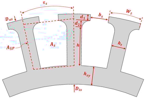
Figure 7.
Overview of the stator geometry.
The tooth head width is calculated using:
where and are, respectively, the stator pole and slot opening, which is initially estimated to . The resolution of the Equation (14) is performed numerically, using a Matlab code. The inner stator diameter is given by:
Table A1, Table A2 and Table A3 of the Appendix A summarize, respectively, the geometric data for the rotor parameters, PM parameters for the 3 configuration, and the stator parameters. It is notable that the phase number influences the stator electric parameters and geometrical parameters, especially the maximum injected current, the spires number and the slot surface.
4. Multiobjective Optimisation Problem
4.1. Problem Formulation
The EM optimisation is an important step in the proposed sizing methodology, as it allows to obtain the best motor performances with respects to the imposed constraints. The objective function was constructed by combining the motor efficiency and weight , as given in Equation (18), which are the representatives of the most important motor variables in the application context.
The coefficients and are used to prioritize both variables between them, with a complementarity condition and thus, the optimisation algorithm will maximise the prioritized variable. In this paper, the motor efficiency and weight are chosen to have the same priority in the optimisation problem, which means that . The motor efficiency is given by:
where , , , and are, respectively, the useful power, copper losses, core losses, and mechanical losses. Their respective expressions are given by:
where (N·m), (rpm), , (W/(m3 · Hz· T2)), (W/(m3 · Hz2 · T2)), f (Hz), (T), V (m3), (m/s) are, respectively, the motor torque, speed, a phase resistance, hysteresis loss coefficient, eddy current loss coefficient, frequency, flux density peak amplitude, core volume, and tangential speed. The phase resistance is directly estimated in terms of winding and stator parameters as:
With q as the number of slots per pole per phase given by , as the spire length given by: , where is the coil head length, which is estimated by . The (Ω · m) and are, respectively, the copper resistivity and the conductor section. °C), °C), and °C) are, respectively, the stator winding temperature, the ambient temperature, and the copper temperature coefficient. The core losses are supposed to be decomposed into losses due to hysteresis, which are proportional to the frequency, and losses due to eddy current, which are proportional to the square of the frequency [35,36,37]. In this case, the stack material is supposed to be homogeneous and isotropic, with a uniform field. The coefficients and depend on stack material, which could be given by the manufacturer. In this paper, the ferromagnetic gauge steel is considered as reference material. The corresponding hysteresis and eddy current coefficient are given by:
The mechanical losses are due to the ventilation and aerodynamics that occur during the revolution between the airbag and the rotor, and friction in the bearings. Their analytical calculation is complicated, because of the vortex flows during rotation. An empirical expression [36], given in Equation (20), is used to estimate these losses, which are in this case proportional to the useful motor power and to the square of the rotor tangential speed . The EM optimisation problem considers three constraints functions, which are: a constraint on the output motor torque that must correspond to the torque imposed by the propeller at a base speed of rpm; a constraint on the electromotive force at the base speed, in order to avoid the flux weakening and to maintain the performances and a constraint the maximal core flux density that must stay below of a reference value of in order to avoid over saturation. Thus, the formulation problem of the EM optimisation is given as follows:
x is the vector of the optimisation parameters, and is composed of a common parameters vector for the four winding configuration cases, as explained in Section 3.2, and it is given by: . A second vector optimisation, specific to each PM topology , is given by:
- SPM configuration: , and .
- V-shape configuration: , and .
- Spoke configuration: and .
It is noticeable that in the of V-shape configuration, the variable represents the ratio of the length to the rotor yoke thickness.
4.2. Optimisation Algorithm
The optimisation is based on the Direct algorithm, belonging to the global non-linear constrained optimisation family. Its working principle consists of minimising a black-box objective function with a bounded normalised search space. The normalisation of search space has no influence on the algorithm convergence as the optimisation variables are bounded. Thus, the search space becomes the unit hyper-cube. DIRECT works by partitioning the unit hypercube into subrectangles with the property that the objective function has been evaluated at each rectangle’s center point. In each iteration, certain “potentially optimal” rectangles are selected for further search; these rectangles are then subdivided, and the function is evaluated at the center points of the newly-formed subrectangles [38,39]. Figure 8 describes the way the algorithm moves towards the optimum of the EM optimisation problem. The algorithm, as well as the EM formulation problem, are implemented using Matlab functions, where the Direct algorithm is explored from the optimisation toolbox of Matlab. The electromagnetic model of the motor is implemented using FEMM, where the inputs are the EM geometry data with the required specifications.
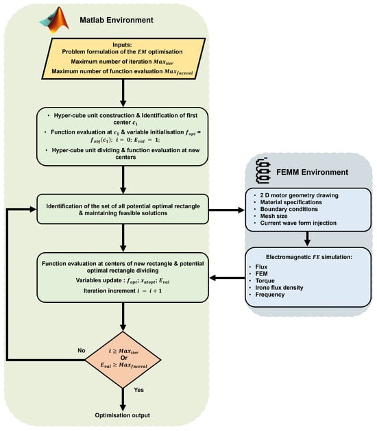
Figure 8.
Direct algorithm optimisation used in the case of the EM problem.
4.3. Optimal Harmonic Current Injection Ratio
In the case of multiphase winding configuration with , it is possible to consider the current injection containing harmonics. This makes it possible to improve the torque density as well as the reliability of the EM. This characteristic comes from the fact that a multiphase motor voltage vector and output torque in the decoupled plan are given by [40]:
m represents the number of the fictious machine, with two phases each, depending on the as follows:
Thus, this formulation makes it possible to transform virtually the multiphase motor to m fictitious machines coupled in series, where each one is associated with a family of odd harmonics. Figure 9 gives the equivalent representation of a multiphase PM motor in the general case of . From this representation, the number of main fictitious and homopolar machines are deduced for the 4 number of phases cases considered in this paper.

Figure 9.
PM Multiphase machine equivalent representation.
The associated odd harmonics for these cases are resumed in the following Table 3, Table 4, Table 5, Table 6 and Table 7:
Table 3.
Odd harmonics for .
Table 4.
Odd harmonics for .
Table 5.
Odd harmonics for .
Table 6.
Odd harmonics for .
Table 7.
SPM EM performances for each case of number of phases.
The term is corresponding to the EMF harmonics, which must be equal to the injected current harmonic in order to create an effective torque. The following expression of the electromagnetic torque explains the relation between the current and the EMF or airgap flux density harmonics:
where K or , , , and are, respectively, a parameter depending on the geometrical and electrical motor parameters, the harmonic of the airgap flux density or the EMF, and harmonic of the injected current. However, the maximisation of the motor output torque, in the case of , requires an optimal harmonic current injection. The sinusoidal current and sinusoidal current with the consideration of higher harmonics are expressed, respectively, as follows:
where , , , , are, respectively, current peak amplitude in the case, current peak amplitude in the case, ratio of the ( harmonic current to the fundamental one, rotor mechanical position, and the number of the phase starting form 0. The determination of the optimal harmonic current injection with the corresponding amplitude is performed in two manners, either to maintain the same value as case or to maintain the same peak amplitude of the injected current as in case . In [41], the authors present an analytical approach to derive the optimal third harmonic current for a 5-phase SPM machine under constraints of peak and RMS value. However, in the case of a higher phase number, especially when , the analytical development is not an efficient solution. In this paper, a new numerical method is developed in the general case. This makes it possible to determine the optimal harmonic current that allows to maximise the motor output torque with consideration peak/RMS constraints. The method is described as follows:
- In the case of peak value, this constraint is expressed as:Thus, the term must be minimised, in order to maximise the motor output torque. This constraint, in this case, consists of finding the ratios that satisfy the following problem:Based on this formulation, the optimal harmonic ratio , in the case of 5 and 6-phase, the optimal third harmonic current injection is . In the case of 7-phase, the optimal third and fifth harmonics current injection are .
- In the case of RMS value, this constraint is expressed as:As in the previous case, in order to maximise the motor torque, the term must be minimised. This constraint, in this case, consists of finding the ratios that satisfy the following problem:It is remarkable that the minimum of the considered function is attainable for ; however, it is possible to inject higher harmonics in a limit of 20% as shown in [41]. Thus, in the optimisation part, they will be the consideration of the current injection in both cases and with peak constraint.
The Figure 10 gives the wave form of the current injection in the cases , + and ++ with the peak constraint. In order to assess the influence of these harmonics, the case optimisation is carried out using current injection with and +.
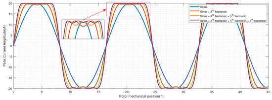
Figure 10.
Current injection wave form for .
5. Results Analysis and Performances Comparison
The optimisation problem, formulated in the previous section, is applied for each configuration of the EM while respecting each scenario of phase number and PM configuration. The optimisation for the scenarios , 6, and 7 was carried out by the injection of current harmonics, where the optimal ratios of the harmonic injection of currents are defined following the method presented in Section 4.3. The cases and 5 were optimised by the injection of sine currents. It should be noted that the injection of the currents considered in the optimization occurs directly in the original plan, i.e., ( and e) for the case . However, it is possible to consider the injection in the decoupled plane . A validation of the designed and optimised EM is performed using FEA, where the results and their analysis, as well as a comparative study of the number of phases, PM configuration, and harmonic current effects on the EM performance, are presented in the following sections. It is notable that every three subfigures of the same column, given below in Section 5.1, Section 5.2, Section 5.3 and Section 5.4 show, respectively, the field lines and flux density in no-load conditions with the corresponding EMFs and its harmonic composition. The optimised geometrical parameters for the whole cases are reported in the Table A4, Table A5 and Table A6 of the Appendix A.
5.1. Design Optimisation Results of the Case
The optimisation of the 3-phase with is carried out using a peak current of A, a current density A/mm2, and DC bus voltage V. Figure 11a–i gives, respectively, the optimisation results for the 3 PM configuration. It is remarkable that in this case, the maximum core flux density amplitude stays below 2 T for the 3 PM positions, which allows avoiding the core saturation. Moreover, the EMF harmonic spectrum shows a weak presence of higher harmonics in comparison to the fundamental frequency .
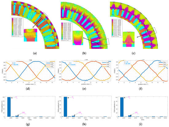
Figure 11.
FEA analysis for the case . (a) Field lines and flux density of the SPM case, (b) Field lines and flux density of the Spoke case, (c) Field lines and flux density of the V-shape case, (d) No-load EMF of the SPM case, (e) No-load EMF of the Spoke case, (f) No-load EMF of the V-shape case, (g) EMF harmonic composition, (h) EMF harmonic composition, (i) EMF harmonic composition.
5.2. Design Optimisation Results of the Case
Regarding the case of the 5-phase with , the optimistion is performed using a peak current of , a current density A/mm2, and DC bus voltage V. Figure 12a–i gives, respectively, the optimisation results for the 3 PM positions, where every three subfigures of the same column show the field lines and flux density in no-load conditions with the corresponding EMFs and its harmonic composition. The obtained EMFs, as excepted, present a non-sinusoidal waveform, where the fifth harmonic presents higher amplitude for the 3 PM positions. The amplitude of the third harmonic increases by passing from the SPM configuration to the IPM (Spoke and V-shape) configuration, which is explained by the higher harmonic component of the IPM configuration. The core saturation is avoided, as the maximum core flux density amplitude remains below 2 T for the 3 PM positions
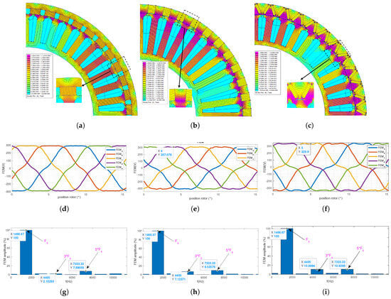
Figure 12.
FEA analysis for the case . (a) Field lines and flux density of the SPM case, (b) Field lines and flux density of the Spoke case, (c) Field lines and flux density of the V-shape case, (d) No-load EMF of the SPM case (e) No-load EMF of the Spoke case, (f) No-load EMF of the V-shape case, (g) EMF harmonic composition, (h) EMF harmonic composition, (i) EMF harmonic composition.
5.3. Design Optimisation Results of the Case
Regarding the case of the 6-phase with , the optimistion is performed using a peak current of A, a current density A/mm2, and DC bus voltage V. The optimisation results for the 3 PM positions are reported in Figure 13a–i, where every three subfigures of the same column show the field lines and flux density in no-load conditions with the corresponding FEM and its harmonic composition. The obtained EMFs present a weak amplitude for the fifth, explaining the low effect on its waveform, especially in the SPM case. However, the amplitude of the third and fifth harmonics increase by passing from the SPM configuration to the IPM (Spoke and V-shape) configuration, which is explained by the higher harmonic component of the IPM configuration.
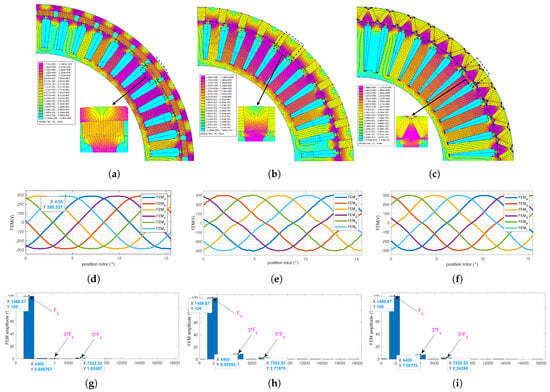
Figure 13.
FEA analysis for the case . (a) Field lines and flux density of the SPM case, (b) Field lines and flux density of the Spoke case, (c) Field lines and flux density of the V-shape case, (d) No-load EMF of the SPM case, (e) No-load EMF of the Spoke case, (f) No-load EMF of the V-shape case, (g) EMF harmonic composition, (h) EMF harmonic composition, (i) EMF harmonic composition.
5.4. Design Optimisation Results of the Case
The optimistion, in the case of the 7-phase with , is performed using a peak current of A, a current density A/mm2, and DC bus voltage V. The optimisation results for the 3 PM positions are reported in Figure 14a–i, where the same conditions are considered as the previous cases. For this motor topology, the obtained EMFs present non-sinusoidal waveform, where the third harmonic amplitude is more present than the fifth and seventh for the 3 PM positions.
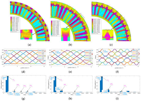
Figure 14.
FEA analysis for the case . (a) Feild lines and flux density of the SPM case, (b) Feild lines and flux density of the Spoke case, (c) Feild lines and flux density of the V-shape case, (d) No-load EMF the SPM case, (e) No-load EMF the Spoke case, (f) No-load EMF the V-shape case, (g) EMF harmonic composition, (h) EMF harmonic composition, (i) EMF harmonic composition.
5.5. Assessment of Number of Phases and PM Configuration Effects on the EM Performances
In order to assess the effect of the number of phases and PM configuration, an FEA magnetostatic simulation is carried out for different configurations. Table 7, Table 8 and Table 9 compare these configurations in terms of average torque (N·m), torque ripple ( (%)), torque mass density ( (N/kg)), torque volume density ( (N·m/L)), motor active mass ( (kg)), PM mass ( (kg)), motor efficiency (%) at rpm, maximum core flux density ( (T)), core losses (W), copper losses (W), and mechanical losses (W). Each table compares the EM performances, for a given PM configuration, for each case of the number of phases.
Table 8.
Spoke PM EM performances for each case of number of phases.
Table 9.
V-shape PM EM performances for each case of number of phases.
The increase in the number of phases, passing from the 3-phase to the higher phase number case, makes it possible to improve the motor performance, such as torque mass and volume motor densities, motor efficiency, weight, volume and losses. However, it is remarkable that the increase in the number of phases by more than five phases causes a drop in the performances as well as an increase in the motor weight, which is explained by the decreased maximum amplitude of the injected current. Regarding the PM configuration effect, it is noticeable that their effects are not conserved by the increasing phase number. For instance, in the case of the 3 and 5 phases, the spoke configuration allows obtaining the best motor in terms of performance and compactness; however, in the cases of the 6 and 7 phases, it is the SPM configuration that allows to obtain the best EM performances.
5.6. Assessment of Current Harmonics Effects on the EM Performances
The case of the 5-phase motor with a spoke configuration is taken as an example to evaluate the effect of harmonic current ratio, where the optimisation, in this case was carried out considering the pure sinusoidal current and non-sinusoidal current. Moreover, the designed PM spoke machine, considering the sinusoidal waveform current in the optimisation part, is used to validate the design approach under a load of N·m at rpm. This load represents the operating point imposed by specifications. Figure 15 gives the instantaneous output torque using and current.
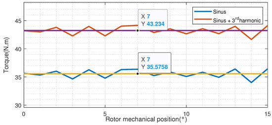
Figure 15.
Torque comparison with and current waveform.
As expected, the consideration of higher harmonic in the current waveform allows for an improvement in the mean torque density of the EM of more than 18 %, in comparison with the classical case of current. This result is confirmed by Figure 15, which shows, respectively, the output instantaneous torque in terms of the current density and the rotor mechanical position for each optimisation case, as well as a comparison of their respective performances, is shown in Table 10, with a current density of A/mm2 and peak amplitude of the injected current of A.
Table 10.
Spoke PM EM performances for each case of number of phases.
Through the plots of Figure 16, it is remarkable that, for both cases, the instantaneous torque increases with the increasing current density, where the torque peak values in the case of optimisation with non-sinusoidal current (b) are much higher than the case with sinusoidal currents (a). Table 10 gives more details about their respective performance, where it is shown that torque, torque mass and volume densities, in the case (b), are improved by 3.28 %, 20%, and 20 %, respectively, with a weight gain of more than 600 g, as well as an increase in the torque ripple.
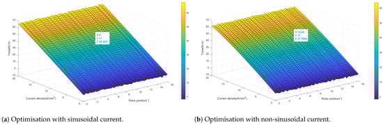
Figure 16.
Instantaneous torque in terms of the rotor mechanical position and the current density.
6. Conclusions
This paper proposed a general and robust design optimisation approach of multiphase PM OR actuators for multirotor aerial vehicle applications. The number of phases and the PM positions were taken as input for design, where 12 motor topologies were designed and analysed. This made it possible to assess their influence on the EM performances, as shown in the comparative study.
The motor design requirements are formulated, where a two-blade fixed pitch propeller was sized in order to assume the considered flight mission. The pre-sizing step, including combination selection, winding design, and analytical sizing, made it possible to validate the motor topology as well as the specifications, especially in terms of the motor output torque. These results are refined using a multiobjective constrained optimisation of the motor efficiency and weight, where constraints on the output torque, EMF, and core maximum flux density amplitude are considered. It was shown that, in comparison with the 3-phase motor, the higher number of phases allows for improved EM performance, torque, torque densities and compactness, as well as reliability with the redundant winding configuration. Moreover, the injection of current, including higher harmonics in the case of multiphase configuration, allowed us to confirm these results.
Some perspectives will be considered in future work, e.g., the integration of FT capabilities and thermal constraints in the multiphase EM design step, considering scenarios of single OC fault, multiple OC fault of adjacent or non-adjacent winding phases and inter-turn short circuit fault (ITSC).
Author Contributions
Conceptualisation, S.C.; methodology, S.C.; software, S.C. and G.K.; formal analysis, S.C.; resources, S.C.; discussion: S.C., G.K., C.M., R.S. and A.A.; writing—original draft preparation, S.C.; writing—review and editing; S.C., G.K., C.M. and A.A. All authors have read and agreed to the published version of the manuscript.
Funding
This research received no external funding.
Data Availability Statement
The data are available upon request to the corresponding author, Saad Chahba: saad.chahba@estaca.fr.
Conflicts of Interest
The authors declare no conflicts of interest.
Appendix A
Table A1.
Stator and Slot parameters for SPM case.
Table A1.
Stator and Slot parameters for SPM case.
| combination | ||||
| Stator outer diameter (mm) | ||||
| Stator inner diameter (mm) | ||||
| Stator yokeless thickness (mm) | 3 | 3 | 3 | 3 |
| Stator pole pitch (mm) | 15 | |||
| width in the case | 11.78 | 10.71 | 10.71 | 10.71 |
| PM materiel | NdFeB | |||
| teeth width (mm) | 3 | 3 | 3 | 2 |
| Tooth hight h (mm) | 27 | 8 | 6.5 | 5 |
| Airgap length (mm) | 0.8 | 0.8 | 0.8 | 0.8 |
| Slot opening (mm) | 3 | 3 | 3 | 3 |
| Tooth head width (mm) | 9.64 | 12.0 | 9.46 | 7.68 |
| Number of turns per coil | 20 | 17 | 14 | 12 |
| Maximum currents (A) | 28 | 17 | 14 | 12 |
| Currents density (A/mm2) | 12 | |||
| DC bus voltage (V) | 400 | |||
| Stator materiel | Pure Iron (M19 Jauge 1.9 mm) | |||
| Stator flux density | 0.9 T | |||
| Teeth width flux density | 1.8 T | |||
Table A2.
Rotor parameters.
Table A2.
Rotor parameters.
| combination | ||||
| Outer rotor diameter (mm) | 206 | 206 | 206 | 206 |
| Stack length (mm) | ||||
| Inner rotor diameter (mm) | 200 | 196 | 200 | 200 |
| combination | 3 | 3 | 3 | 3 |
| Rotor materiel | Pure Iron (M19 Jauge 1.9 mm) | |||
| Rotor flux density | 0.9 T | |||
Table A3.
Stator and Slot parameters for IPM and Spoke case.
Table A3.
Stator and Slot parameters for IPM and Spoke case.
| combination | ||||
| Stator outer diameter (mm) | ||||
| Stator inner diameter (mm) | 170 | |||
| Stator yokeless thickness (mm) | 3 | 3 | 3 | 3 |
| Stator pole pitch (mm) | 13 | 15 | 13 | |
| width in the case | 12.55 | 11.41 | 11.41 | 11.41 |
| width in the case | 3 | 3 | 3 | 3 |
| PM materiel | NdFeB | |||
| Tooth width (mm) | 3 | 3 | 3 | 2 |
| Tooth hight h (mm) | 24.27 | 5.3 | 6 | 4.2 |
| Airgap length (mm) | 0.8 | 0.8 | 0.8 | 0.8 |
| Slot opening (mm) | 3 | 3 | 3 | 3 |
| Tooth head width (mm) | 10 | 12.58 | 10 | 8.13 |
| Number of turns per coil | 20 | 17 | 14 | 12 |
| Maximum currents (A) | 28 | 17 | 14 | 12 |
| Currents density (A/mm2) | 12 | |||
| DC bus voltage (V) | 400 | |||
| Stator materiel | Pure Iron (M19 Jauge 1.9 mm) | |||
Table A4.
Optimised geometrical parameters for the SPM configuration.
Table A4.
Optimised geometrical parameters for the SPM configuration.
| SPM Configuration | |||||||||||
|---|---|---|---|---|---|---|---|---|---|---|---|
| 3 | 102.00 | 11.33 | 40.78 | 1.78 | 3.42 | 3.42 | 3.17 | 0.30 | 6 | 1.50 | 1.50 |
| 5 | 91.00 | 8.67 | 37.34 | 2.00 | 4.78 | 4.78 | 4.17 | 0.25 | 15 | 1.11 | 2.70 |
| 6 | 92.89 | 10.00 | 37.11 | 2.70 | 3.42 | 3.42 | 3.17 | 0.38 | 14 | 2.00 | 1.50 |
| 7 | 93.00 | 11.00 | 40.83 | 2.33 | 3.42 | 3.42 | 4 | 0.30 | 14 | 1.67 | 1.12 |
Table A5.
Optimised geometrical parameters for the Spoke configuration.
Table A5.
Optimised geometrical parameters for the Spoke configuration.
| Spoke Configuration | ||||||||||
|---|---|---|---|---|---|---|---|---|---|---|
| 3 | 86.67 | 7.05 | 42.00 | 1.4 | 12.12 | 5.33 | 0.38 | 4 | 1.40 | 1.33 |
| 5 | 80.33 | 10.11 | 37.50 | 1.80 | 6.02 | 3.93 | 0.38 | 15 | 2.50 | 1.33 |
| 6 | 93.00 | 8.33 | 34.50 | 2.7 | 8.00 | 3.93 | 0.35 | 13 | 1.89 | 2.00 |
| 7 | 80.33 | 8.33 | 39.89 | 1.5 | 8.00 | 3.93 | 0.38 | 12 | 1.50 | 1.33 |
Table A6.
Optimised geometrical parameters for the V-shape configuration.
Table A6.
Optimised geometrical parameters for the V-shape configuration.
| V-Shape Configuration | ||||||||||||
|---|---|---|---|---|---|---|---|---|---|---|---|---|
| 3 | 103.78 | 10.00 | 45.89 | 1.20 | 13.00 | 4.00 | 2.00 | 0.37 | 5 | 2.00 | 1.33 | 24.50 |
| 5 | 80.33 | 10.1 | 37.5 | 1.78 | 6.03 | 3.93 | 2.00 | 0.38 | 15 | 2.00 | 1.33 | 24.50 |
| 6 | 91.00 | 9.50 | 38.56 | 1.80 | 9.11 | 3.75 | 2.33 | 0.30 | 12 | 1.50 | 1.33 | 26.67 |
| 7 | 92.00 | 9.50 | 41.33 | 2.00 | 9.00 | 3.75 | 2 | 0.30 | 14 | 1.80 | 1.11 | 26.00 |
References
- Johnson, W.; Silva, C. NASA concept vehicles and the engineering of advanced air mobility aircraft. Aeronaut. J. 2022, 126, 59–91. [Google Scholar] [CrossRef]
- Wheeler, P.; Sirimanna, T.S.; Bozhko, S.; Haran, K.S. Electric/Hybrid-Electric Aircraft Propulsion Systems. Proc. IEEE 2021, 109, 1115–1127. [Google Scholar] [CrossRef]
- Ganev, E. Selecting the Best Electric Machines for Electrical Power-Generation Systems: High-performance solutions for aerospace More electric architectures. IEEE Electrif. Mag. 2014, 2, 13–22. [Google Scholar] [CrossRef]
- Nøland, J.K.; Leandro, M.; Suul, J.A.; Molinas, M. High-Power Machines and Starter-Generator Topologies for More Electric Aircraft: A Technology Outlook. IEEE Access 2020, 8, 130104–130123. [Google Scholar] [CrossRef]
- Cao, W.; Mecrow, B.C.; Atkinson, G.J.; Bennett, J.W.; Atkinson, D.J. Overview of Electric Motor Technologies Used for More Electric Aircraft (MEA). IEEE Trans. Ind. Electron. 2012, 59, 3523–3531. [Google Scholar] [CrossRef]
- Swaminathan, N.; Reddy, S.R.P.; RajaShekara, K.; Haran, K.S. Flying Cars and eVTOLs—Technology Advancements, Powertrain Architectures, and Design. IEEE Trans. Transp. Electrif. 2022, 8, 4105–4117. [Google Scholar] [CrossRef]
- Zhao, T.; Wu, S.; Cui, S. Multiphase PMSM With Asymmetric Windings for More Electric Aircraft. IEEE Trans. Transp. Electrif. 2020, 6, 1592–1602. [Google Scholar] [CrossRef]
- Alvarez, P.; Satrústegui, M.; Elósegui, I.; Martinez-Iturralde, M. Review of High Power and High Voltage Electric Motors for Single-Aisle Regional Aircraft. IEEE Access 2022, 10, 112989–113004. [Google Scholar] [CrossRef]
- Madonna, V.; Giangrande, P.; Gerada, C.; Galea, M. Thermal analysis of fault-tolerant electrical machines for aerospace actuators. IET Electr. Power Appl. 2019, 13, 843–852. [Google Scholar] [CrossRef]
- Rottach, M.; Gerada, C.; Hamiti, T.; Wheeler, P.W. Fault-tolerant electrical machine design within a Rotorcraft Actuation Drive System optimisation. In Proceedings of the 6th IET International Conference on Power Electronics, Machines and Drives (PEMD 2012), Bristol, UK, 27–29 March 2012; pp. 1–6. [Google Scholar] [CrossRef]
- Sciascera, C.; Giangrande, P.; Brunson, C.; Galea, M.; Gerada, C. Optimal design of an electro-mechanical actuator for aerospace application. In Proceedings of the 41st Annual Conference of the IEEE Industrial Electronics Society, IECON 2015, Yokohama, Japan, 9–12 November 2015; pp. 001903–001908. [Google Scholar] [CrossRef]
- Noia, D.L.P.; Rizzo, R. Design of a five-phase permanent-magnet motor for the electric steering of an aircraft nose landing gear. IET Electr. Syst. Transp. 2017, 7, 327–333. [Google Scholar] [CrossRef]
- Fabri, G.; Parasiliti, F.; Tursini, M.; Villani, M.; Castellini, L. PM brushless motor for helicopters electric tail rotor drive system. In Proceedings of the IEEE International Electric Machines and Drives Conference (IEMDC), Miami, FL, USA, 21–24 May 2017; pp. 1–7. [Google Scholar] [CrossRef]
- Villani, M.; Parasiliti, F.; Tursini, M.; Fabri, G.; Castellini, L. PM brushless motors comparison for a Fenestrontype helicopter tail rotor. In Proceedings of the International Symposium on Power Electronics, Electrical Drives, Automation and Motion (SPEEDAM), Capri, Italy, 22–24 June 2016; pp. 22–27. [Google Scholar] [CrossRef]
- Bianchi, N.; Michieletto, D.; Cinti, L.; Contò, C.; Carlet, P.G.; Brunetti, M.; Nesci, A. Permanent Magnet Synchronous Motor Drives for More-Electric Aircraft. In Proceedings of the International Symposium on Power Electronics, Electrical Drives, Automation and Motion (SPEEDAM), Sorrento, Italy, 22–24 June 2022; pp. 871–876. [Google Scholar] [CrossRef]
- Cheng, Z.; Cao, Z.; Hwang, J.T.; Mi, C. A Novel Single-Turn Permanent Magnet Synchronous Machine for Electric Aircraft. Energies 2023, 16, 1041. [Google Scholar] [CrossRef]
- Tallerico, T.F. NASA Reference Motor Designs for Electric Vertical Takeoff and Landing Vehicles. In Proceedings of the AIAA/IEEE Electric Aircraft Technologies Symposium (EATS), Denver, CO, USA, 11–13 August 2021; pp. 1–41. [Google Scholar]
- Islam, M.S.; Mikail, R.; Husain, I. Slotless Lightweight Motor for Aerial Applications. IEEE Trans. Ind. Appl. 2019, 55, 5789–5799. [Google Scholar] [CrossRef]
- Tallerico, T.F.; Smith, A.D.; Chapman, J.W. Design Optimization Study of Fault Tolerant and Redundant Motor Drivetrains for Urban Air Mobility Vehicles. In Proceedings of the IEEE International Electric Machines & Drives Conference (IEMDC), San Francisco, CA, USA, 15–18 May 2023; pp. 1–5. [Google Scholar] [CrossRef]
- Kumar, J.; Fernandes, B.G. Multi-three-phase FSCW High-speed High-power-dense Inset Bread-loaf PMSM for the Electric VTOL Application. In Proceedings of the IEEE International Electric Machines & Drives Conference (IEMDC), San Francisco, CA, USA, 15–18 May 2023; pp. 1–7. [Google Scholar] [CrossRef]
- Chahba, S.; Sehab, R.; Morel, C.; Krebs, G.; Akrad, A. Fast Sizing Methodology and Assessment of Energy Storage Configuration on the Flight Time of a Multirotor Aerial Vehicle. Aerospace 2023, 10, 425. [Google Scholar] [CrossRef]
- Liscouët, J.; Pollet, F.; Jézégou, J.; Budinger, M.; Delbecq, S.; Moschetta, J.M. A methodology to integrate reliability into the conceptual design of safety-critical multirotor unmanned aerial vehicles. Aerosp. Sci. Technol. 2022, 127, 10768. [Google Scholar] [CrossRef]
- Simmons, B.M.; Gresham, J.L.; Woolsey, C.A. Aero-Propulsive Modeling for Propeller Aircraft Using Flight Data. J. Aircr. 2022, 60, 36773. [Google Scholar] [CrossRef]
- Wolnik, T.; Styskala, V.; Mlcak, T. Study on the Selection of the Number of Magnetic Poles and the Slot-Pole Combinations in Fractional Slot PMSM Motor with a High Power Density. Energies 2022, 15, 215. [Google Scholar] [CrossRef]
- Aslan, B.; Semail, E.; Korecki, J.; Legranger, J. Slot/pole combinations choice for concentrated multiphase machines dedicated to mild-hybrid applications. In Proceedings of the IECON 37th Annual Conference of the IEEE Industrial Electronics Society, Melbourne, VIC, Australia, 7–10 November 2011; pp. 3698–3703. [Google Scholar] [CrossRef]
- Gong, J.; Zahr, H.; Semail, E.; Trabelsi, M.; Aslan, B.; Scuiller, F. Design Considerations of Five-Phase Machine with Double p/3p Polarity. IEEE Trans. Energy Convers. 2019, 34, 12–24. [Google Scholar] [CrossRef]
- Min, S.G.; Sarlioglu, B. Investigation of electromagnetic noise on pole and slot number combinations with possible fractional-slot concentrated windings. In Proceedings of the IEEE Transportation Electrification Conference and Expo (ITEC), Chicago, IL, USA, 22–24 June 2017; pp. 241–246. [Google Scholar] [CrossRef]
- EL-Refaie, A.M. Fractional-Slot Concentrated-Windings Synchronous Permanent Magnet Machines: Opportunities and Challenges. IEEE Trans. Ind. Electron. 2010, 57, 107–121. [Google Scholar] [CrossRef]
- Dajaku, G.; Roth, C. Comparison Study of Different FSCWs with Flux Barrier Stator. In Proceedings of the IEEE International Electric Machines & Drives Conference (IEMDC), San Francisco, CA, USA, 15–18 May 2023; pp. 1–6. [Google Scholar] [CrossRef]
- Li, G.J.; Ren, B.; Zhu, Z.Q. Design guidelines for fractional slot multi-phase modular permanent magnet machines. IET Electr. Power Appl. 2017, 11, 1023–1031. [Google Scholar] [CrossRef]
- Cros, J.; Viarouge, P. Synthesis of high performance PM motors with concentrated windings. IEEE Trans. Energy Convers. 2002, 17, 248–253. [Google Scholar] [CrossRef]
- Castano, S.M.; Jiang, J.W.; Bilgin, B.; Sathyan, A.; Dadkhah, H.; Emadi, A. An investigation of slot-pole combinations for interior permanent magnet synchronous machines with different magnet topologies. In Proceedings of the IEEE International Electric Machines and Drives Conference (IEMDC), Miami, FL, USA, 21–24 May 2017; pp. 1–8. [Google Scholar] [CrossRef]
- Charih, F.; Dubas, F.; Espanet, C.; Chamagne, D. Performances comparison of PM machines with different rotor topologies and similar slot and pole numbers. In Proceedings of the International Symposium on Power Electronics Power Electronics, Electrical Drives, Automation and Motion, Sorrento, Italy, 20–22 June 2012; pp. 56–59. [Google Scholar] [CrossRef]
- Duffy, M.; Sevier, A.; Hupp, R.; Perdomo, E.; Wakayama, S. Propulsion Scaling Methods in the Era of Electric Flight. In Proceedings of the AIAA/IEEE Electric Aircraft Technologies Symposium (EATS), Cincinnati, OH, USA, 9–11 July 2018; pp. 1–23. [Google Scholar]
- Li, Z.; Che, S.; Zhao, H.; Zhang, L.; Wang, P.; Du, S.; Zhang, H.; Feng, Y.; Sun, H. Loss analysis of high-speed permanent magnet motor based on energy saving and emission reduction. Energy Rep. 2023, 9, 2379–2394. [Google Scholar] [CrossRef]
- Elhomdy, E.; Liu, Z.; Li, G. Thermal and Mechanical Analysis of a 72/48 Switched Reluctance Motor for Low-Speed Direct-Drive Mining Applications. Appl. Sci. 2019, 9, 2722. [Google Scholar] [CrossRef]
- Grellet, G. Pertes dans les machines tournantes. Tech. L’ingénieur 1989, D3450 V1. [Google Scholar] [CrossRef]
- Jones, D.R. Direct Global Optimization Algorithm. In Encyclopedia of Optimization; Springer: Boston, MA, USA, 2001. [Google Scholar]
- Jones, D.R.; Martins, J.R.R.A. The DIRECT algorithm: 25 years Later. J. Glob. Optim. 2021, 79, 521–566. [Google Scholar] [CrossRef]
- Semail, E.; Kestelyn, X.; Bouscayrol, A. Right harmonic spectrum for the back-electromotive force of an n-phase synchronous motor. In Conference Record of the 2004 IEEE Industry Applications Conference, 2004, Proceedings of the 39th IAS Annual Meeting, Seattle, WA, USA, 3–7 October 2004; IEEE: Washington, DC, USA, 2004; p. 78. [Google Scholar] [CrossRef]
- Wang, K.; Gu, Z.Y.; Liu, C.; Zhu, Z.Q. Design and Analysis of a Five-Phase SPM Machine Considering Third Harmonic Current Injection. IEEE Trans. Energy Convers. 2018, 33, 1108–1117. [Google Scholar] [CrossRef]
Disclaimer/Publisher’s Note: The statements, opinions and data contained in all publications are solely those of the individual author(s) and contributor(s) and not of MDPI and/or the editor(s). MDPI and/or the editor(s) disclaim responsibility for any injury to people or property resulting from any ideas, methods, instructions or products referred to in the content. |
© 2024 by the authors. Licensee MDPI, Basel, Switzerland. This article is an open access article distributed under the terms and conditions of the Creative Commons Attribution (CC BY) license (https://creativecommons.org/licenses/by/4.0/).