Article

Effect of Impellers on the Cooling Performance of a Radial Pre-Swirl System in Gas Turbine Engines

College of Energy and Power Engineering, Nanjing University of Aeronautics and Astronautics, Nanjing 210016, China
*
Author to whom correspondence should be addressed.
Aerospace 2024, 11(3), 187; https://doi.org/10.3390/aerospace11030187
Submission received: 17 January 2024 / Revised: 19 February 2024 / Accepted: 23 February 2024 / Published: 26 February 2024
(This article belongs to the Special Issue New Insights into Aerodynamics and Cooling in Gas Turbine Engines)

Abstract

:
Impellers are utilized to increase pressure to ensure that a radial pre-swirl system can provide sufficient cooling airflow to the turbine blades. In the open literature, the pressurization mechanism of the impellers was investigated. However, the effect of impellers on the cooling performance of the radial pre-swirl system was not clear. To solve the aforementioned problem, tests were carried out to assess the temperature drop in a radial pre-swirl system with various impeller configurations (impeller lengths l/b ranging from 0 to 0.333). Furthermore, numerical simulations were used to investigate the flow and heat transfer characteristics of the radial pre-swirl system at high rotating Reynolds numbers. Theoretical and experimental investigations revealed that the pre-swirl jet and output power generate a significant temperature drop, but the impellers have no obvious effect on the system temperature drop. By increasing the swirl ratio, the impellers reduce the field synergy angle and thus improve convective heat transfer on the turbine disk. In addition, increasing the impeller length can reduce the volume-averaged field synergy angle and improve heat transfer, but the improvement effectiveness decreases as the impeller length increases. Thus, the study concluded that impellers could improve the cooling performance of the radial pre-swirl system by enhancing disk cooling.

1. Introduction

The high temperature of the turbine inlet directly threatens the high-pressure turbine blades and disks. To extend the life of the turbine blades and disks, a radial pre-swirl system is employed [1,2]. The airflow enters the radial pre-swirl system through the pre-swirl nozzles, then accelerates through the receiver holes into the rotor, and ultimately enters the turbine blades via a co-rotating cavity and supply holes, as illustrated in Figure 1. The radial pre-swirl system is responsible for supplying cooling airflow to the turbine blades and cooling the high-temperature turbine disks. Furthermore, because of the increased turbine inlet temperature, high-pressure and low-temperature airflow is beneficial for cooling the turbine blades.
Gas turbine engines feature three types of pre-swirl systems: radial pre-swirl systems, axial pre-swirl systems, and cover-plate pre-swirl systems [1,3,4]. The pre-swirl nozzle, receiver hole, rotating cavity, and supply hole are geometrical characteristics common to pre-swirl systems. Commonly, the pre-swirl nozzles generate significant temperature and pressure drops. Although flow and heat transfer have been extensively studied in the axial and cover-plate pre-swirl systems [5,6,7,8], the radial pre-swirl system has received less attention. Because of the compact layout and the requirement for high pressures, the airflow in the radial pre-swirl system is structured to flow from a low radius to a high radius. In previous studies, the effect of the geometrical parameters of the pre-swirl nozzle was investigated to improve its adiabatic effectiveness and discharge coefficient [9,10,11]. To optimize the flow structure further, Lee et al. [7] proposed vane-shaped pre-swirl nozzles and performed a parameter sensitivity analysis. For the receiver hole, Lee et al. [12] investigated the effect of tilt angle and number. Furthermore, Liu et al. [13] developed vane-shaped receiver holes to enable a high-radius system with low leakage and high temperature drop.
The rotating cavity is an essential component of the radial pre-swirl system which is responsible for increasing the airflow pressure. Owen and Firouzian et al. [14,15,16] were the first to conduct theoretical and experimental studies on the flow inside rotating cavities, and they classified the flow field into four regions: the source region, the Ekman layer, the core region, and the sink region. Under engineering conditions, the rotating cavity does not have Ekman layers and a core region because of the high flow rate required for the turbine blades [17,18]. Thus, the impellers were used to improve the pressurization efficiency of the rotating cavity by significantly increasing the swirl ratio. Previous research [19] investigated the impact of disk shape factors and operating conditions on flow and heat transfer in rotating cavities. The pressurization mechanism of the impeller was investigated in depth, and the results showed that enhanced centrifugal flow could improve centrifugal pressure rise [17]. However, the effect of the impeller on the temperature drop in the radial pre-swirl system is unclear.
Zhang et al. [20] pointed out that the flow and heat transfer in the cavity directly affects the safety of the gas turbine. Thus, different configurations have been proposed to enhance the cooling of the turbine disk. Xia et al. [21] proposed a double-row pre-swirl nozzle to improve heat transfer at a high radius. Ma et al. [22,23] optimized the pre-swirl nozzles and receiver holes in a twin-web turbine disk to decrease the disk temperature and temperature non-uniformity. Furthermore, Taamneh [24] attempted to employ heat pipes to transfer heat from the hot end to the cold end to make the temperature on the turbine disk more uniform. However, this configuration is not yet applicable. In addition, Tang and Cao et al. [25,26] used Bayesian modeling to tackle the inverse heat transfer problem on the disk. It should be noted that the radial pre-swirl system operates in a high-temperature environment, and thermal conditions significantly impact cooling performance. Thus, Lin et al. [27] analyzed the effect of non-uniform wall temperature on the aerodynamic characteristics in a turbine disk cavity. However, the effect of the impellers on heat transfer in the radial pre-swirl system is still unknown.
In general, the open literature revealed the impeller pressurization process, and plenty of analysis has been carried out on pre-swirl nozzles and receiver holes. However, the effect mechanism of impellers on the cooling performance of a radial pre-swirl system has not been investigated. In this study, the theory and tests are utilized to investigate the conversion of power and heat in a radial pre-swirl system. Furthermore, numerical simulations are performed to study the effect of the impellers on the field synergy angle and heat transfer.

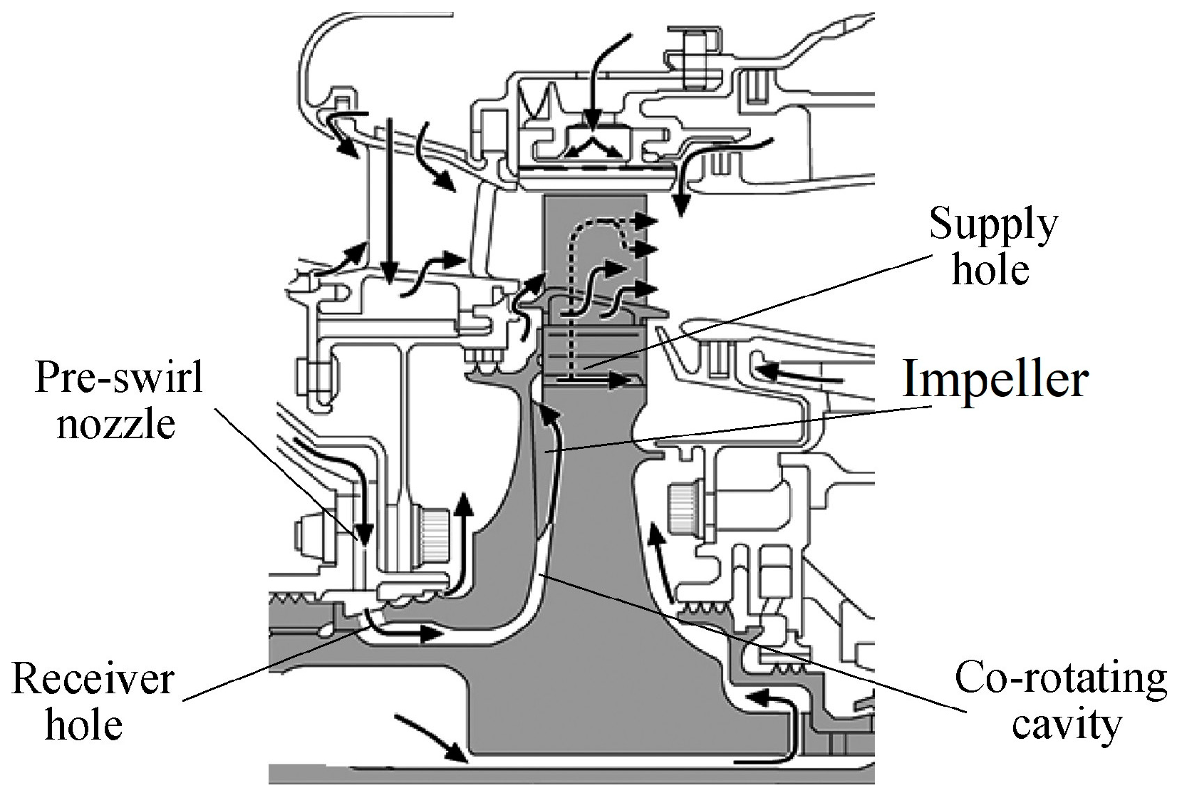
2. Test Configuration
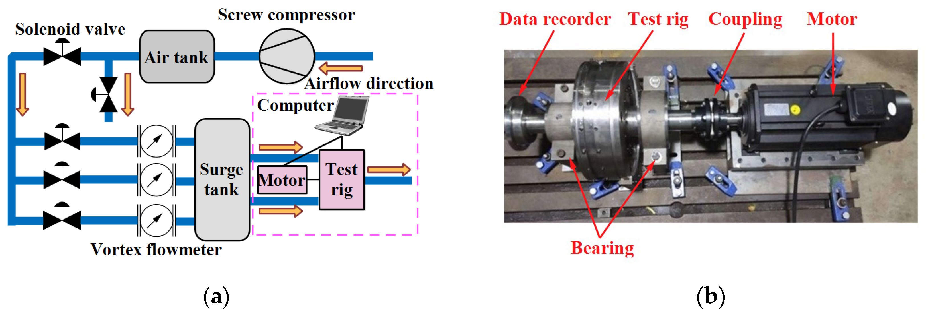
2.1. Test System

As illustrated in Figure 2, a test system for investigating the radial precession system is developed. A screw compressor provides the airflow supply for the test system, and the flow rate is controlled by five solenoid valves. The airflow enters the test rig through four static holes and is discharged into the atmosphere after passing through the test rig, as indicated by the blue arrows. A 15kW motor rotates the test rig directly via a coupling, with the rotating speed controlled by a frequency converter. Furthermore, a data recorder is attached to the shaft end.

2.2. Test Rig and Measuring Instruments

Figure 3a illustrates the geometrical parameters of the test rig. The outer radius b of the rotating cavity is 142 mm. The inlet radius rni/b and outlet radius rno/b of the pre-swirl nozzle are 0.929 and 0.586, respectively. The inlet radius rri/b and outlet radius rro/b of the receiver hole are 0.558 and 0.532, respectively. The radius rs/b of the centerline of the supply hole is 0.909. The thickness h/b of the pre-swirl nozzle and the diameter ds/b of the receiver hole are 0.034 and 0.037, respectively. It should be noted that the concave cavity is a co-rotating cavity with an equal inlet and outlet radius.
In the configuration, the tangential angle of the pre-swirl nozzle is 15° and the receiver hole does not have any inclined component. In this study, four impeller disks are investigated, as shown in Figure 2b. Due to the small axial width of the rotating cavity, the impellers and the upstream disk are machined in one piece. When the upstream and downstream disks are assembled, the impellers will fit closely to the downstream disk. The low radius rii/b of the impellers is fixed at 0.542 and their length l/b ranges from 0 to 0.333, where l = riorii. Especially, when l = 0, the radial pre-swirl system does not have impellers. The number of pre-swirl nozzles, receiver holes, impellers, and supply holes are 21, 51, 48, and 48, respectively. Table 1 demonstrates the test conditions.
Four vortex-shedding flowmeters are used to record the flow rate, their test range and accuracy are 20~1000 m3/h and ±1 m3/h, respectively. A photoelectric tachometer is used to measure the rotating speed, its test range and accuracy are 2.5~99999 rev/min and ±1 rev/min, respectively. Several K-type thermocouples are used to measure the temperature; their test range and accuracy are 150~700 K and ±0.5 K, respectively. The pressure is measured by a pressure scanner, measuring from 0 kPa to 500 kPa with an accuracy of 0.01% reading value.

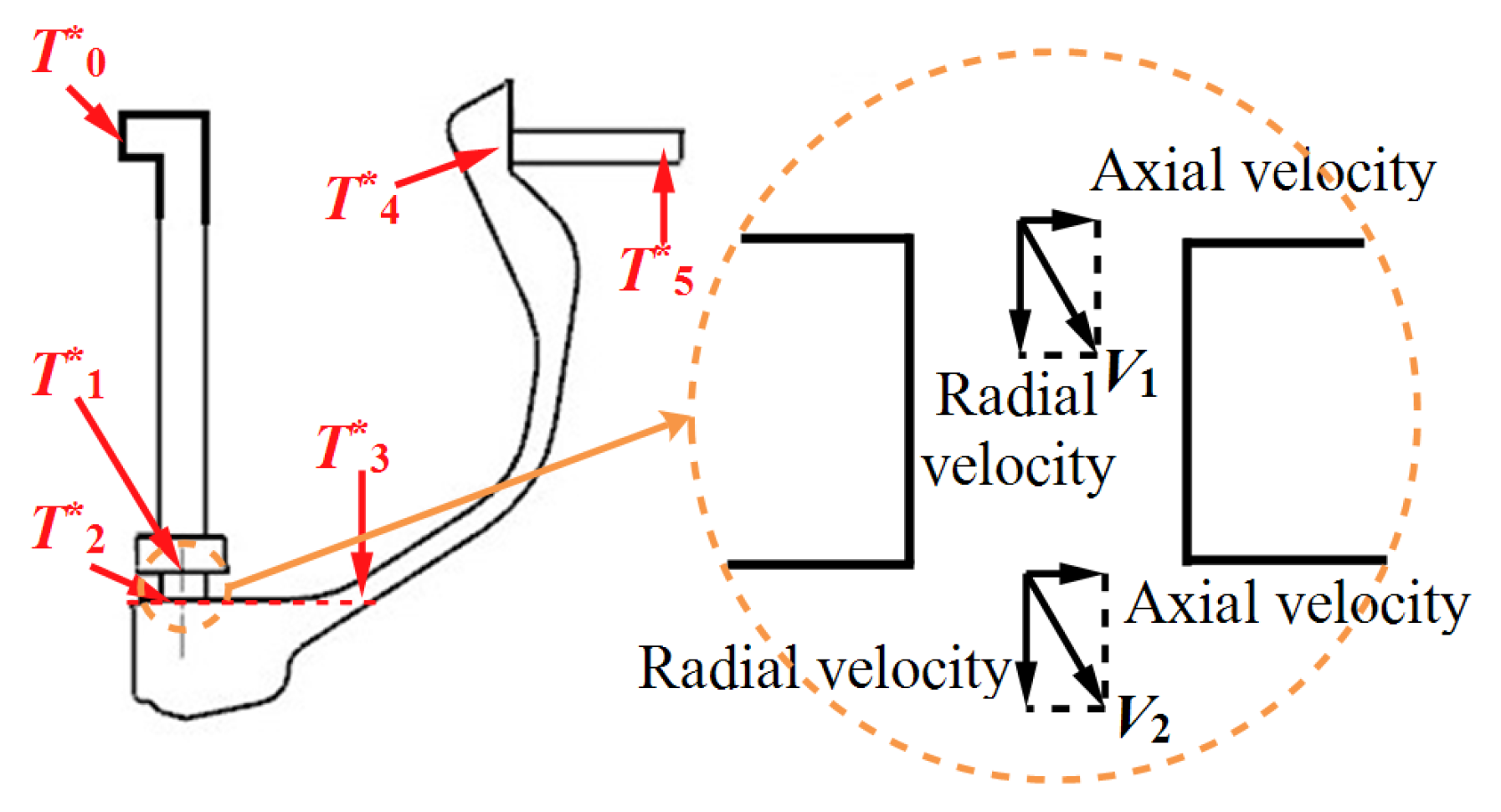
2.3. Dimensional Parameters

To evaluate the effect of impellers on the cooling performance of the radial pre-swirl system, some dimensionless parameters need to be determined. The rotating Reynolds number R e ϕ and dimensionless flow rate C w are critical parameters to control flow and heat transfer, and they determine the operating conditions of the radial pre-swirl system [4].
R e ϕ = ρ ω b 2 / μ
C w = m / μ b
where ρ, ω, and μ denote density, rotating angular velocity, and dynamic viscosity, respectively. In the rotor, the relative total pressure and relative total temperature of the airflow are the cooling parameters for the turbine disks and turbine blades. The pressure coefficient and temperature coefficient are defined as follows.
C p = ( p i n * p o u t * ) / p i n *
C T = ( T i n * T o u t * ) / T i n *
where p i n * and T i n * are the total pressure and total temperature at the system inlet, respectively. p o u t * and T o u t * denote the relative total pressure and relative total temperature at the system outlet, respectively.
For pre-swirl nozzles, the swirl ratio can characterize the pre-swirl velocity and be used to evaluate temperature drop [9]. Furthermore, Shen et al. [28] demonstrated that the swirl ratio in a rotating cavity is proportional to temperature rise.
S r = V ϕ / ω b

3. Computational Procedure

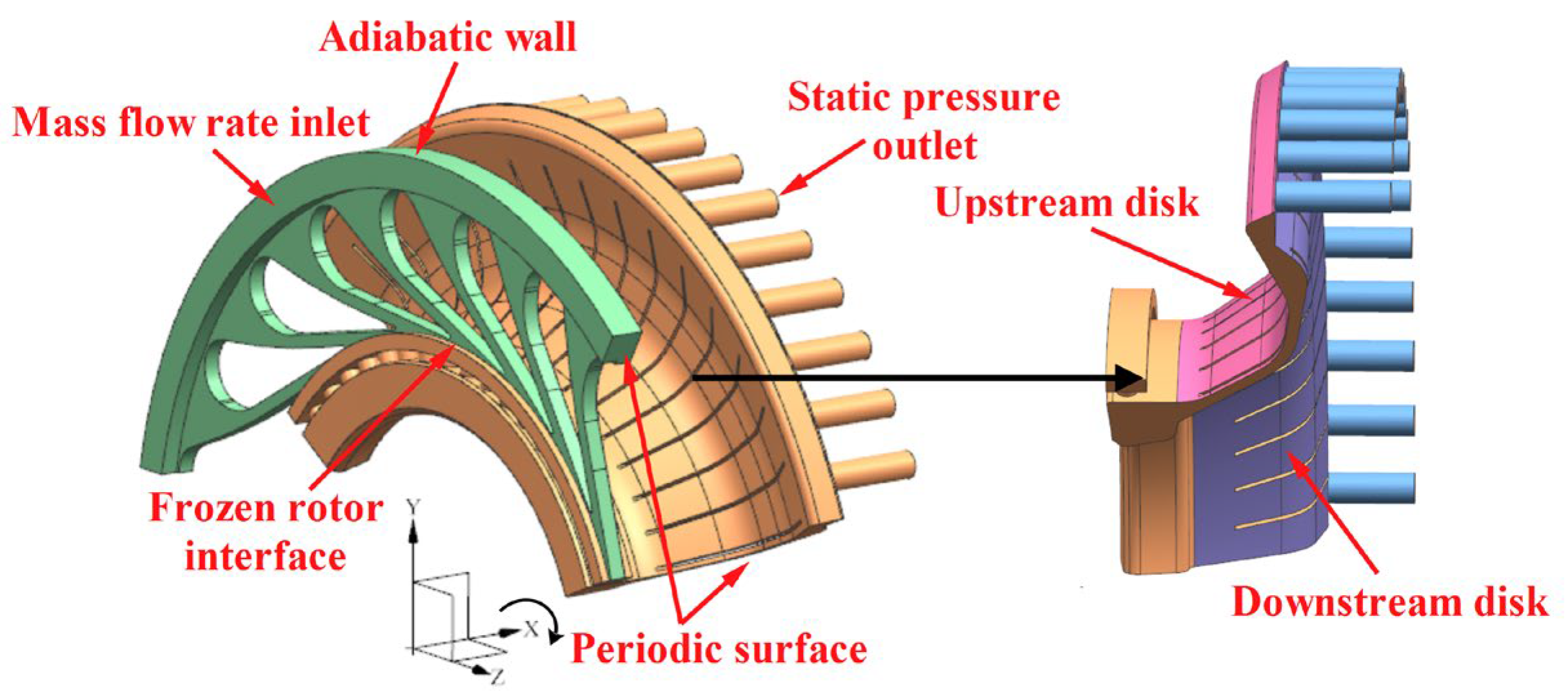
3.1. Computational Model and Boundary Conditions

The computational model is extracted from the test rig as shown in Figure 4. The airflow enters the rotor via the pre-swirl nozzles, then flows from the low radius to the high radius via the concave and rotating cavities, and ultimately exits the computational domain through the supply holes. To save computational resources, a computational domain of 1/3 of the entire model is chosen, and the computational domain sides are thus set as periodic surfaces.
For the aforementioned model, the system inlet is set as the mass flow rate boundary. The stator, receiving holes and concave cavity are defined as adiabatic walls. Furthermore, the upstream and downstream disks are identified for later investigation. With reference to Lin et al. [27], a heat flux of 20,000 W/m2 is specifically applied to the supply holes, impellers, downstream disk, and upstream disk. In practice, the radial pre-swirl system must supply high-pressure airflow to meet the turbine blade cooling requirements. As a result, the system outlet is configured to the static pressure boundary. For the steady simulation of pre-swirl systems, the frozen rotor algorithm is recommended to be applied to the rotor-stator interface [8,29,30,31]. The specific boundary conditions are shown in Table 2.

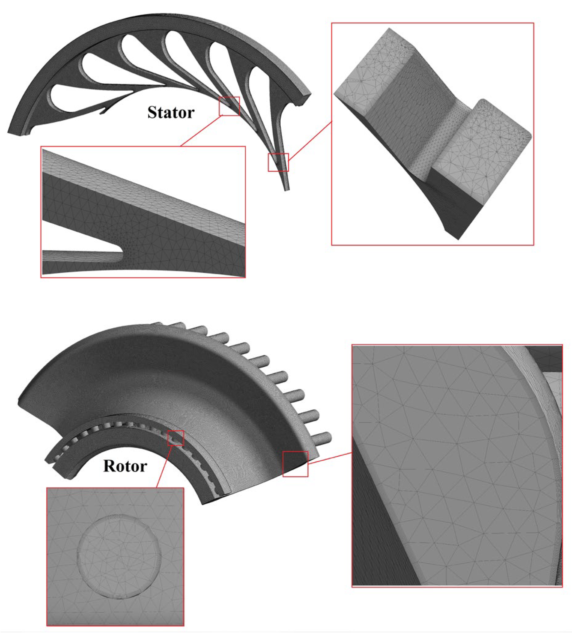
3.2. Computational Method and Grid
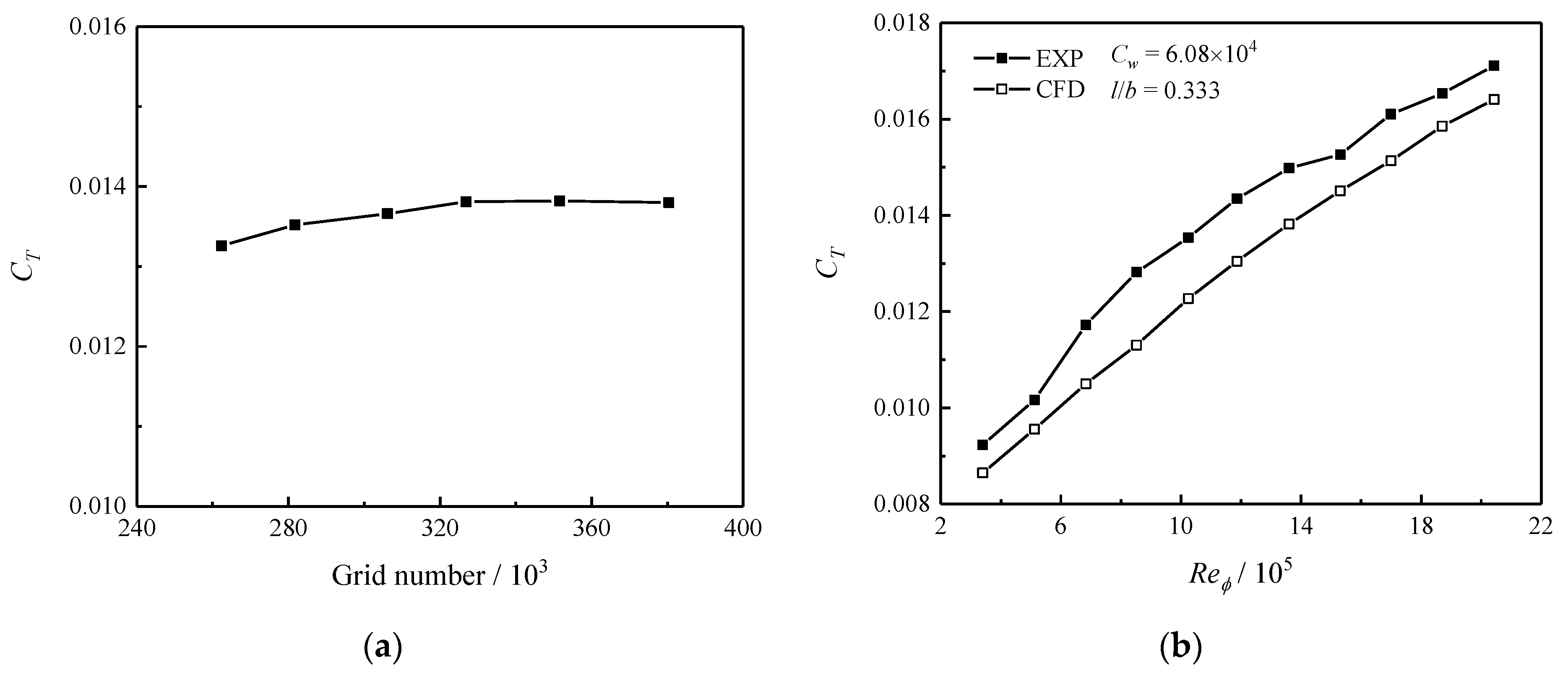
CFX software is used to simulate steady flow and heat transfer. Compared to the k-ε model, the RNG k-ε model is able to predict the swirl flow better due to its descriptive mechanism [32,33]. Thus, the RNG k-ε model is chosen. The airflow is defined as an ideal compressible fluid. The total energy algorithm and scalable wall function are used to simulate the heat transfer and boundary layer, respectively.
The Reynolds mean momentum equation is:
ρ U t + ρ U i U j x j x j μ U i x j + U j x i = p x i ρ u i u j ¯ x j + S M i
where p is the modified pressure and S M i is the sum of body forces and the fluctuating Reynolds stress.
p = p + 2 3 μ U k x k
Meshing software is used to generate unstructured grids, as shown in Figure 5. The maximum grid size is 1.8 mm. The grid height of the first layer near the wall is set to 0.02 mm, and its growth rate is 1.1. In particular, the grids in the pre-swirl nozzles and the receiver holes are encrypted to 1 mm.

3.3. Validation

A grid independence test is performed, as shown in Figure 6a. The rotating Reynolds number and dimensionless flow rate are 1.36 × 10⁶ and 6.08 × 10⁴, respectively. The impeller length l/b is 0.333. The temperature coefficient shows a tendency to increase and then flatten out as the grid number increases. To save computational resources, 3.5 million is chosen as the reference.
Tests are used to validate the effectiveness of the computational model and methods, as shown in Figure 6b. The validation model is a radial pre-swirl system with l/b = 0.333 impellers. It should be noted that the validation model does not consider labyrinth sealing. Overall, the relative average error between the experimental and numerical results is 7.26%, indicating that the methods of this study are valid.

4. Theoretical Analysis

Before analyzing the experimental and numerical results, we attempt to investigate theoretically the temperature drop in the radial pre-swirl system based on the conservation of energy. We classified the temperature sites inside the radial pre-swirl system into six groups based on geometrical parameters, as shown in Figure 7. T 0 * indicates the total temperature at the system inlet in the absolute coordinate system. T 1 * , T 2 * , T 3 * , T 4 * , and T 5 * are the respective relative total temperatures at the receiver hole inlet, receiver hole outlet, rotating cavity inlet, supply hole inlet, and system outlet. Because the heat flux on the wall is a separately analyzable heat source, theoretical analysis treats all walls of the radial pre-swirl system as adiabatic.
In the adiabatic absolute coordinate system, the total temperature between the system inlet and the receiver hole inlet remains constant, therefore,
T 0 * = T 1 + S r 1 ω r 1 2 2 C p
where S r 1 and r 1 denote the swirl ratio and radius at the receiver hole inlet. C p represents the specific heat capacity at constant pressure. The relative total temperature at the receiver hole inlet is
T 1 * = T 1 + S r 1 1 ω r 1 2 2 C p + V 1 2 2 C p
where V 1 indicates the vector sum of the axial and radial velocities at the receiver hole inlet, as shown in Figure 7. Thus, the relative total temperature drop between the system inlet and the receiver hole inlet is expressed as:
Δ T 0 1 * = S r 1 ω r 1 2 2 C p S r 1 1 ω r 1 2 2 C p V 1 2 2 C p
In the rotating coordinate system, the static temperature drop in the receiver hole is
T 1 T 2 = w 2 2 w 1 2 2 C p + ω 2 r 1 2 ω 2 r 2 2 2 C p
where w 1 and w 2 denote the relative velocity at the inlet and outlet of the receiver hole, respectively, (vector sum of the axial, radial, and relative tangential velocities). r 2 is the radius at the receiver hole outlet. At the same time, the relative total temperature at the receiver hole outlet is
T 2 * = T 2 + S r 2 1 ω r 2 2 2 C p + V 2 2 2 C p
where V 2 is the vector sum of the axial and radial velocities at the receiver hole outlet, as shown in Figure 7. Thus, the temperature drop in the receiver hole is
Δ T 1 2 * = ω 2 r 1 2 ω 2 r 2 2 2 C p
the relative total temperature at the rotating cavity inlet is
T 3 * = T 3 + S r 3 1 ω r 3 2 2 C p + V 3 2 2 C p
where S r 3 and r 3 denote the swirl ratio and radius at the rotating cavity inlet, respectively. In the concave cavity, ignoring the conversion of power and heat between the airflow and the wall, the absolute total temperature is constant.
T 2 + S r 2 ω r 2 2 2 C p + V 2 2 2 C p = T 3 + S r 3 ω r 3 2 2 C p + V 3 2 2 C p
where V 3 is the vector sum of the axial and radial velocities at the rotating cavity inlet. Thus, the temperature drop between the receiver hole outlet and the rotating cavity inlet is
Δ T 2 3 * = S r 3 ω r 3 2 2 C p S r 2 ω r 2 2 2 C p + S r 2 1 ω r 2 2 2 C p S r 3 1 ω r 3 2 2 C p
when the rotating cavity is empty or the low radius of the impellers is higher than the receiver hole outlet, the swirl ratio at the receiver hole outlet is basically equal to that at the rotating cavity inlet ( S r 2 S r 3 ). Thus, the relative total temperature drop in the concave cavity is 0. In the rotating cavity, the static temperature drop is
T 3 T 4 = w 4 2 w 3 2 2 C p + ω 2 r 3 2 ω 2 r 4 2 2 C p
where w 3 and w 4 denote the relative velocity at the rotating cavity inlet and the supply hole inlet, respectively. r 4 is the radius at the supply hole inlet. The relative total temperature at the supply hole inlet is
T 4 * = T 4 + w 4 2 2 C p
therefore, the relative total temperature drop in the rotating cavity is
Δ T 3 4 * = ω 2 r 3 2 ω 2 r 4 2 2 C p
in the supply hole, the absolute velocity of the airflow increases rapidly, with a static temperature drop of
T 4 T 5 = w 5 2 w 4 2 2 C p
where w 5 indicates the relative velocity at the supply hole outlet. The relative total temperature at the supply hole outlet is
T 5 * = T 5 + w 5 2 2 C p
as a result, the temperature drop Δ T 4 5 * in the supply hole is 0. Overall, the system temperature drop is expressed as
Δ T * = 2 S r 1 1 ω r 1 2 2 C p V 1 2 2 C p + ω 2 r 1 2 ω 2 r 2 2 2 C p + ω 2 r 3 2 ω 2 r 4 2 2 C p
In theory, the pre-swirl jet and the centrifugal force in the receiving hole are the main factors causing the temperature drop (the first and third terms of Equation (22)). Conversely, the centrifugal force in the rotating cavity will generate a temperature rise. In practice, the impellers increase the pressure in the radial pre-swirl system, reducing density and increasing velocity. Shen et al. [17] have shown that there is no significant increase in density in the rotating cavity, due to the low swirl ratio limiting the pressurization efficiency of the rotating cavity. Thus, under ideal conditions (flow rate is constant and leakage is ignored), Equation (22) indicates that the impellers have no significant effect on the system temperature drop.

5. Results and Discussion

5.1. Numercial Results

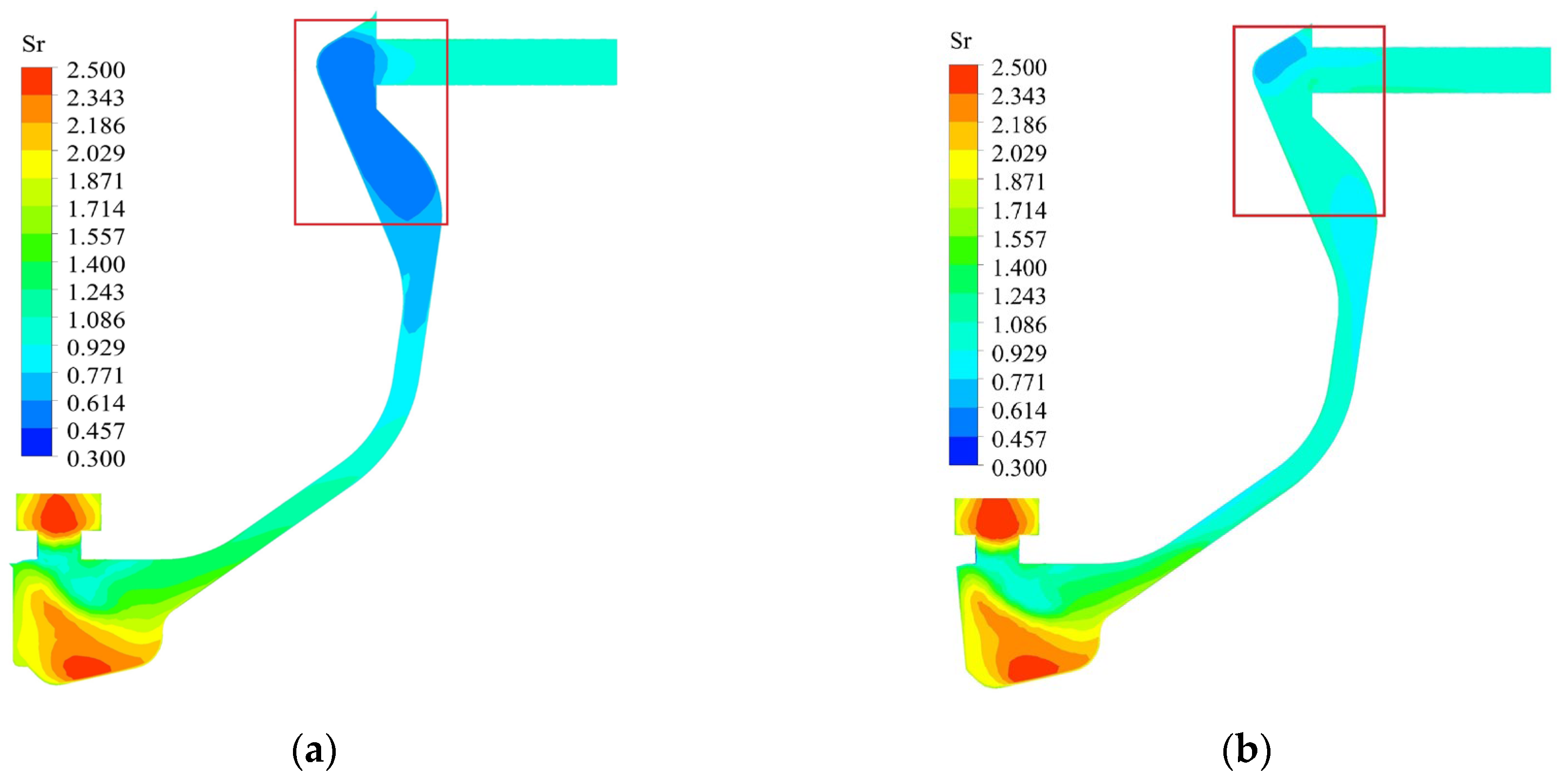
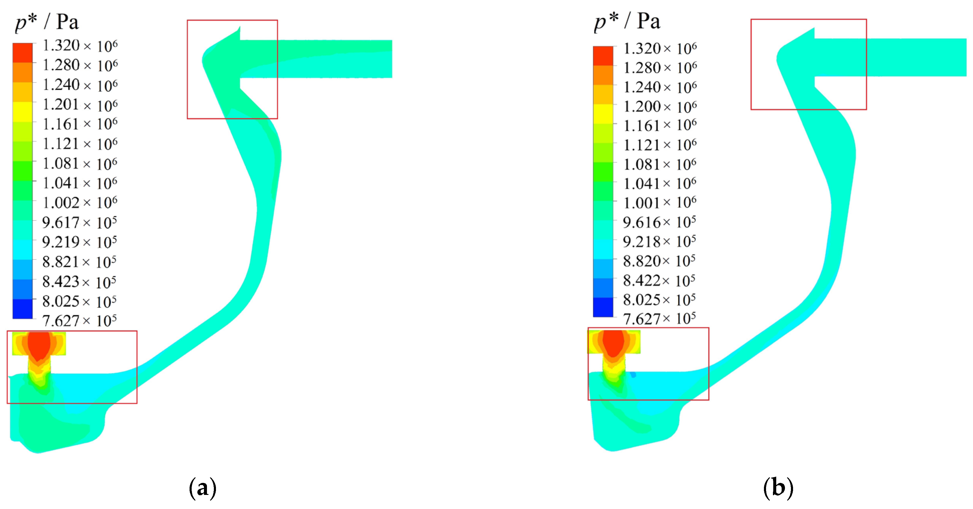
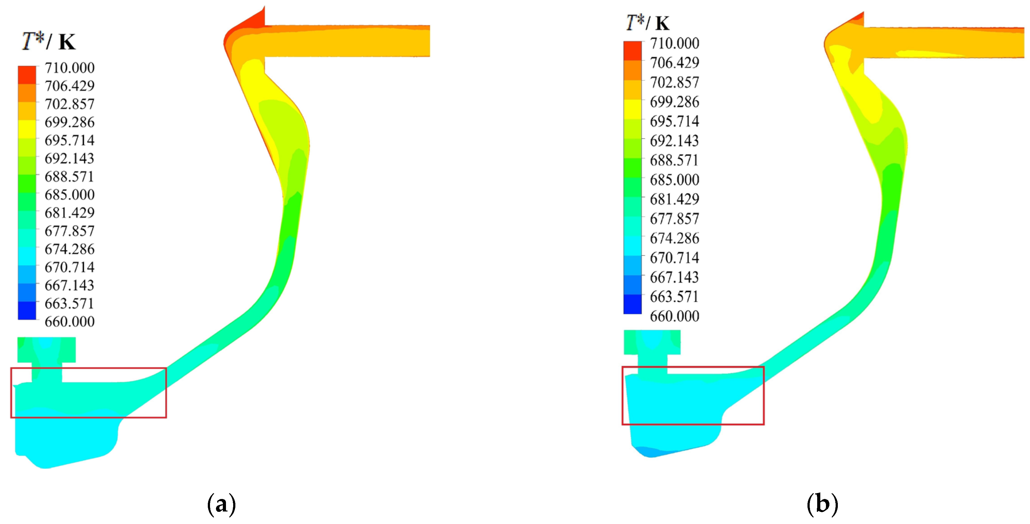
5.1.1. Flow Structure and Distribution of Pressure and Temperature

Figure 8 illustrates the swirl ratio in the rotors. Because of the accelerating effect of the pre-swirl nozzle, the receiver hole inlet has a high swirl ratio. However, the receiving hole forces the swirl ratio to be reduced to around 1. According to angular momentum conservation, the swirl ratio increases gradually with decreasing radius in the concave cavity. Furthermore, it can be found in detail that the swirl ratio at the receiver hole outlet and the rotating cavity inlet are essentially the same. In the radial pre-swirl system without impellers, the swirl ratio in the rotating cavity decreases as the radius increases. However, the impellers increase the swirl ratio in the corresponding region to 1. Overall, the impellers affect the swirl ratio in the rotating cavity and have no significant effect on the receiving hole and concave cavity.
Figure 9 shows the relative total pressure in the rotors. The receiver hole has a significant local pressure loss compared to the rotating cavity and supply hole. To provide low-temperature airflow to the turbine blades, the radial pre-swirl system generates a high-velocity jet. Therefore, the high swirl ratio at the pre-swirl nozzle outlet inevitably generates a strong energy dissipation. In a rotating cavity, the static pressure rise is associated with the swirl ratio as follows [16]:
Δ p = ω 2 r 1 r 2 ρ r S r 2 d r
Regardless of axial and radial velocities, the relative total pressure rise is:
Δ p * = ω 2 r 1 r 2 ρ r S r 2 d r + S r 2 1 2 ω 2 r 2 2 S r 1 1 2 ω 2 r 1 2
Therefore, the impellers can improve the pressurization efficiency of the rotating cavity by increasing the swirl ratio. Furthermore, it can be found in detail that the local pressure loss at the supply hole is reduced due to the reduced relative tangential velocity. Statistically, the relative total pressure at the inlet of the rotor without and with impellers is 1.294 kPa and 1.284 kPa, respectively.
Figure 10 illustrates the distribution of relative total temperature in the two radial pre-swirl systems. Because of the input power in the rotating coordinate system, the relative total temperature in the rotating cavity tends to increase with increasing radius. Compared with the radial pre-swirl system without impellers, the relative total temperature at the outlet of the radial pre-swirl system with impellers is reduced by 0.3K. It is crucial to note that the effect of the impellers on the relative total temperature is weak due to the low swirl ratio limiting the pressurization efficiency, which is consistent with the theoretical investigation (see Equation (22)).

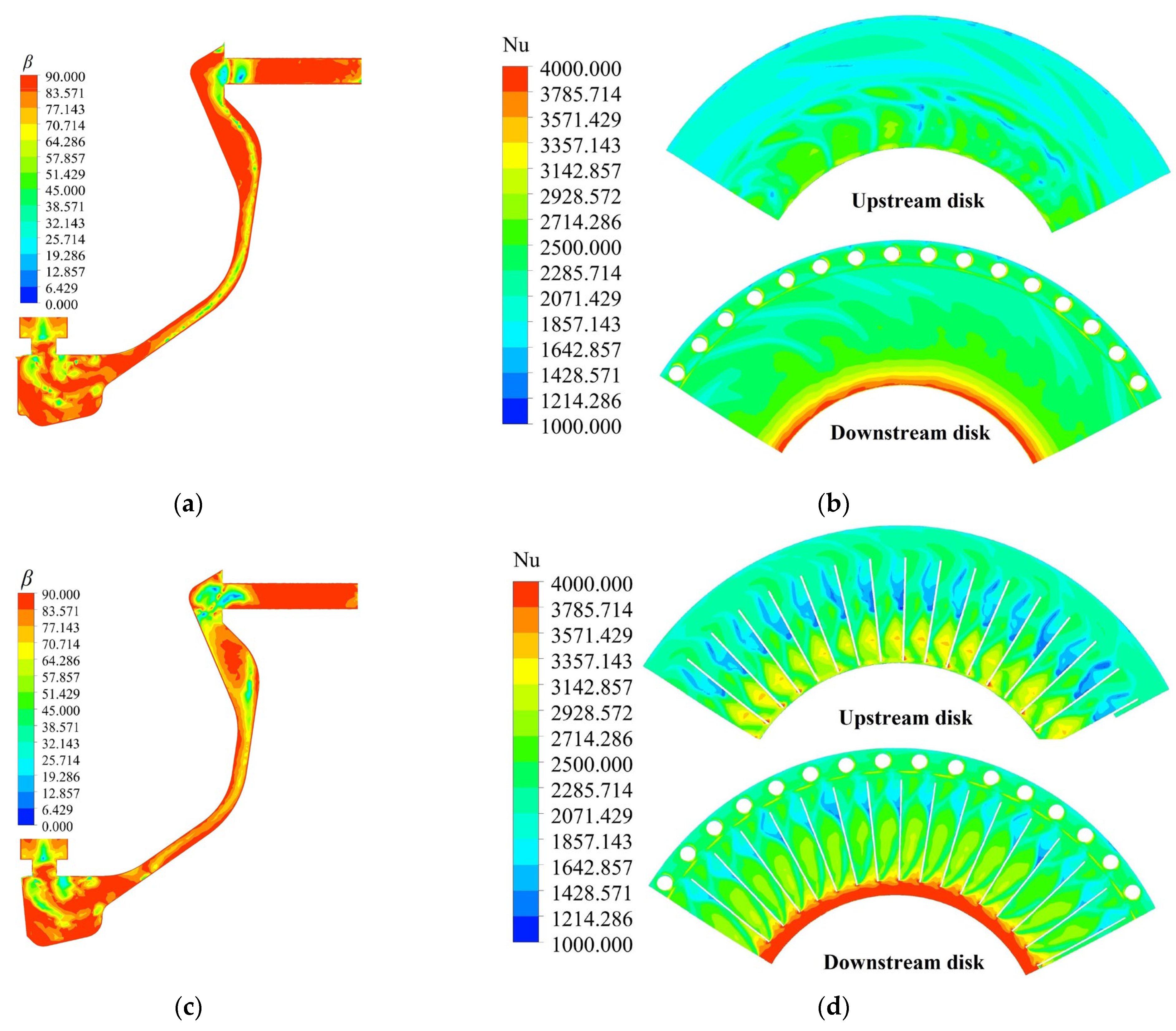
5.1.2. Heat Transfer on the Disks

The radial pre-swirl system not only needs to provide cooling airflow to the turbine blades but also is responsible for cooling the high-temperature turbine disk, and thus, controlling the tip clearance [34]. The velocity field and temperature field are very important for the flow and heat transfer in a radial pre-swirl system. For single-phase flow and heat transfer, Guo et al. [35,36] proposed the field synergy principle and used the field synergy angle β to quantify the heat transfer. The field synergy angle is defined as the angle formed by the velocity vector and the temperature gradient, and convective heat transfer improves as the field synergy angle decreases.
c o s β = V · T V · T
Figure 11 shows the distribution of the field synergy angle in the two radial pre-swirl systems and the distribution of the Nusselt number N u = q w r / k ( T w T r ) , where k and T r = 660 K denote the thermal conductivity of air and the reference temperature, respectively. The cloud of the Nusselt number rotates clockwise. The velocity vector in the receiver hole converges with the temperature gradient due to the rapid increase in swirl ratio, causing the field synergy angle to decrease rapidly. When airflow exits the receiver hole, the high relative velocity causes the field synergy angle to develop rapidly. In the rotating cavity, the jet generates a high Nusselt number on the downstream disk, and the high radial velocity minimizes the field synergy angle. Especially, as the impellers change the flow structure, some of the airflow at the low radius flows to the upstream disk [17]. Therefore, the field synergy angle in the corresponding region decreases and the Nusselt number increases. Furthermore, at the high radius, the impellers reduce the relative tangential velocity by increasing the swirl ratio, thus improving the heat transfer on the disks. It is important to note that there is a low Nusselt number near the leeward surface at the top of the impellers, which may be due to vortices.
Figure 12 depicts the distribution of temperature on the disks. Because of the high Nusselt number, the disks have a low temperature at their low radius. It should be noted that the current impeller configuration will deteriorate local heat transfer and cause a temperature rise. In future research, the impeller profile must be optimized to remove the negative effects of local vortices.
The volume-averaged field synergy angle in the rotating cavity is used to analyze the comprehensive effect of impellers and operating conditions on heat transfer, as shown in Figure 13. The volume-averaged field synergy angle decreases as the rotating Reynolds number increases, owing to a more uniform velocity field as a result of the decreasing swirl ratio at the rotating cavity inlet. As the dimensionless flow rate increases, the volume-averaged field synergy angle shows a weak increasing trend. Furthermore, as the impeller length increases, the field synergy angle decreases, indicating that convective heat transfer on the turbine disk improves. Compared with the radial pre-swirl system without impellers, the volume-averaged field synergy angle of the radial pre-swirl system with impellers (l/b = 0.333) is reduced by 3.47%. It can be observed that the decreased rate in the volume-averaged field synergy angle decreases with increasing impeller length, which is due to the fact that the growth of the longer impeller has less effect on the velocity field.

5.2. Experimental Results

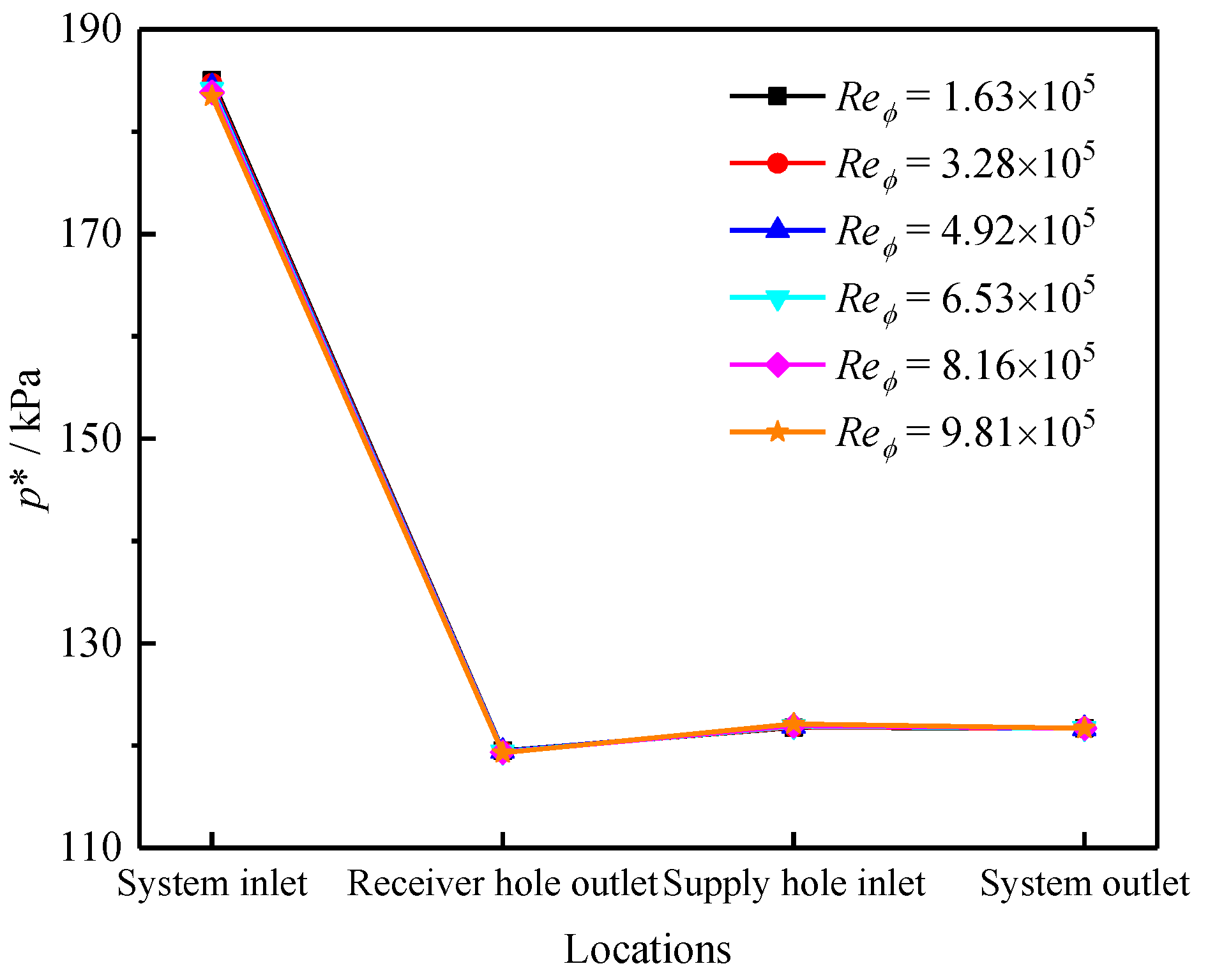
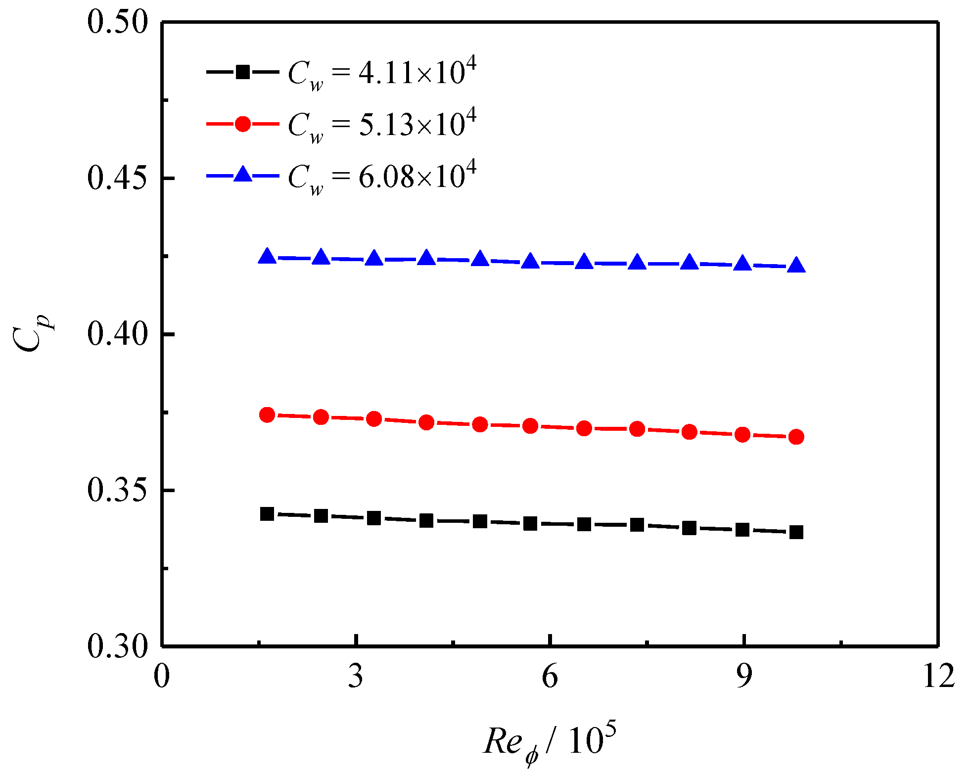
5.2.1. Pressure Drop Characteristics

Figure 14 illustrates the effect of the rotating Reynolds number on the relative total pressure along the path in the radial pre-swirl system. The pressure rise in the rotating cavity increases with the increase in the rotating Reynolds number, and the reduced swirl ratio at the pre-swirl nozzle outlet results in a lower local pressure loss. For the supply hole, the local pressure loss increases due to the increased rotating Reynolds number increasing the relative velocity. Especially, the change in the stagnation state and the high local pressure loss at the receiver hole cause an extremely high pressure drop between the system inlet and the receiver hole outlet, which is even higher than the system pressure drop. In addition, the relative total pressure at the system inlet decreases as the rotating Reynolds number increases. However, it should be noted that the effect of the rotating Reynolds number on the system pressure drop is weak under the test range, as shown in Figure 15. However, because the mass flow rate has a significant effect on the swirl ratio at the pre-swirl nozzle outlet, the system pressure drop increases significantly with the increase in the dimensionless flow rate.

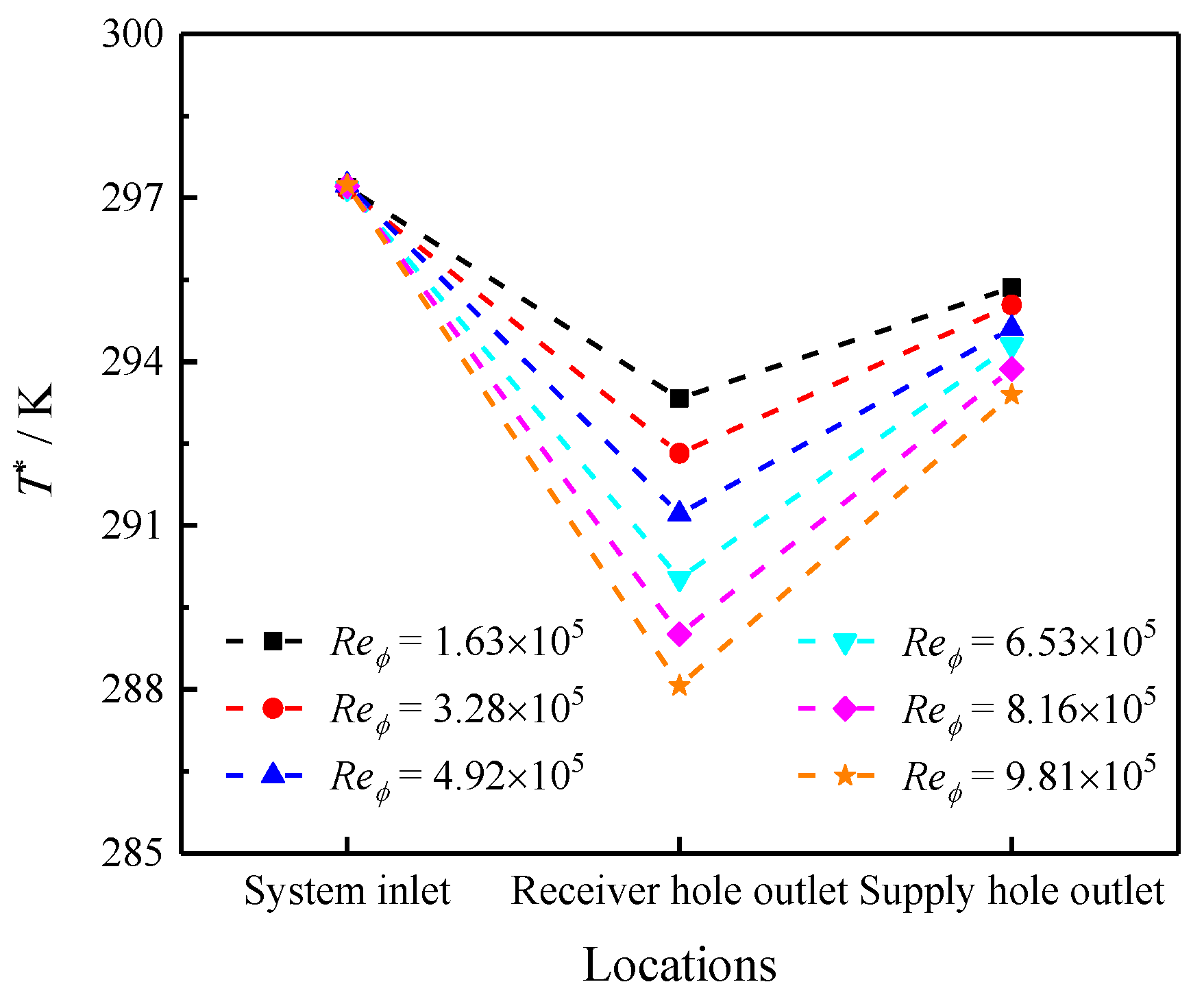
5.2.2. Temperature Drop Characteristics

Figure 16 illustrates the effect of the rotating Reynolds number on the relative total temperature in the radial pre-swirl system (l/b = 0.333). Because of the rotating coordinate system, the relative total temperature decreases significantly between the system inlet and the receiver hole outlet. Furthermore, the relative total temperature between the receiver hole outlet and the supply hole outlet increases as the input power of the impellers increases. During the test, the temperature at the system inlet is determined by the screw compressor, thus, the rotating Reynolds number has no effect. The rotating coordinate system accelerates as the rotating Reynolds number increases, and the relative total temperature at the receiver hole outlet steadily falls. However, the temperature rise in the rotating cavity is growing.
The effect of rotating Reynolds number and dimensionless flow rate on the temperature coefficient is shown in Figure 17. As the rotating Reynolds number increases, the swirl ratio at the receiver hole inlet decreases, decreasing output power and temperature. However, the temperature coefficient shows an increasing trend due to the acceleration of the rotating coordinate system. Furthermore, because the swirl ratio at the receiver hole inlet increases with increasing dimensionless flow rate, the temperature coefficient increases with increasing output power. It can be observed that the impellers have no significant effect on the temperature coefficient, which is consistent with theoretical analysis. In addition, the tests were not completed in just one day due to the need to replace the impeller disks, which resulted in changes in the ambient temperature and system inlet conditions.

6. Conclusions

In this study, the effect of the impellers on the cooling performance of a radial pre-swirl system was investigated. The theory was developed to analyze the conversion mechanism of power to heat in the radial pre-swirl system. Tests were carried out to investigate the effect of the impellers and operating conditions on the system temperature drop. Furthermore, numerical simulations were utilized to analyze the flow and heat transfer characteristics in the radial pre-swirl system in detail. The main conclusions of this study are as follows:
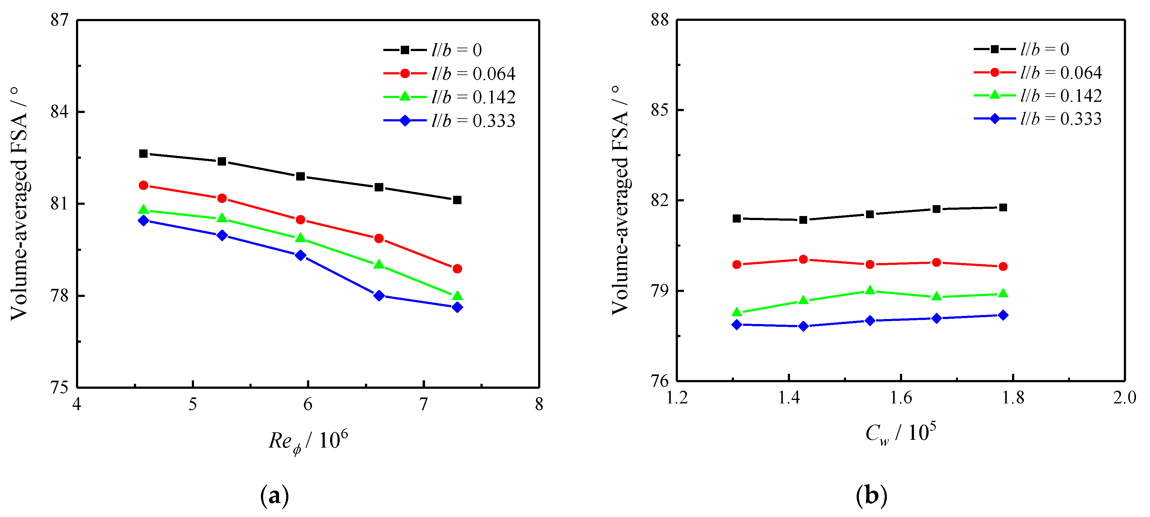
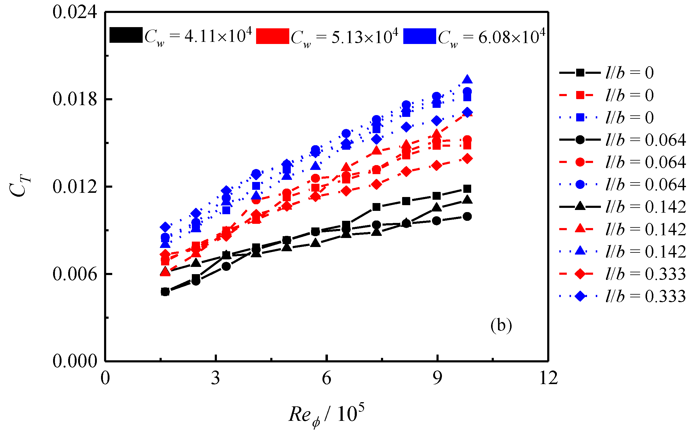
  • Compared with the radial pre-swirl system without impellers, the radial pre-swirl system with impellers has a higher swirl ratio in the rotating cavity. Due to the direct influence of the impellers, the relative tangential flow is restricted, which improves the pressurization efficiency of the rotating cavity and decreases local pressure loss at the supply hole. Furthermore, the system pressure drop and system temperature drop decrease and increase as the impeller grows, respectively.
  • Reducing the system pressure drop is beneficial to increasing the system temperature drop. The impellers decrease the pressure at the rotor inlet by improving the aerodynamic performance of the radial pre-swirl system. At the same time, the increasing pre-swirl velocity increases the temperature drop caused by the acceleration of the airflow.
  • The impellers enhance heat transfer on the disks. Because the impellers reduce the relative tangential velocity, the angle between the velocity vector and the temperature gradient decreases, resulting in a low field synergy angle and a high Nusselt number. However, vortices present at the top of the impellers worsen the local heat transfer.
  • As the rotating Reynolds number increases, the system pressure drop and system temperature drop decrease and increase, respectively. The increased rotating Reynolds number reduces the local pressure loss at the receiver hole and increases the pressure rise in the rotating cavity, thus reducing the system pressure drop. Because the mass flow rate directly affects the swirl ratio at the pre-swirl nozzle outlet, the system pressure drop and system temperature drop increase significantly with the increase in the dimensionless flow rate.
This study provides insight into the thermal characteristics of the radial pre-swirl system with impellers. Theoretical and experimental results show that when the mass flow rate is constant, the impellers have no significant effect on the system temperature drop. However, in engineering, the mass flow rate is influenced by the impellers. Thus, future research should focus on the effect of impellers on the flow distribution in gas turbine engines. Additionally, modifying the impeller profile is a method of improving heat transfer on the disks.

Author Contributions

Conceptualization, Writing—Original Draft, Methodology, Software, Validation, W.S.; Writing—Review and Editing, Supervision, S.W.; Visualization, Data Curation, X.L. All authors have read and agreed to the published version of the manuscript.

Funding

The authors gratefully acknowledge the financial support for this project from the National Science and Technology Major Project of China (No. 2017-III-0011-0037).

Data Availability Statement

Data are contained within the article.

Acknowledgments

The authors thank Chai for his help with the experiment.

Conflicts of Interest

The authors declare no conflicts of interest.

Abbreviations

bOuter radius of the rotating cavity
CmDimensionless flow rate
CpSpecific heat capacity at the constant pressure
CTTemperature coefficient
dsDiameter of the supply hole
hThickness of the pre-swirl nozzle
lImpeller length
mMass flow rate
NuNusselt number
rRadius
ReϕRotating Reynolds number
SrSwirl ratio
TStatic temperature
T*Relative total temperature
VϕTangential velocity in the stationary frame
wRelative velocity
wrelShaft power
Greek
ρDensity
ωRotating angular velocity
βField synergy angle
μDynamic viscosity
Subscripts
noPre-swirl nozzle outlet
niPre-swirl nozzle inlet
outSystem outlet
inSystem inlet
ioOuter radius of the impeller
iiInner radius of the impeller
roReceiver hole outlet
riReceiver hole inlet
ϕTangential component

References

  1. Zhang, F.; Wang, X.; Li, J. Numerical investigation of flow and heat transfer characteristics in radial pre-swirl system with different pre-swirl nozzle angles. Int. J. Heat Mass Transf. 2016, 95, 984–995. [Google Scholar] [CrossRef]
  2. Zhang, F.; Wang, X.; Li, J. Numerical investigation on the flow and heat transfer characteristics in radial pre-swirl system with different fillet radius at the junction of inlet cavity and nozzle. Appl. Therm. Eng. 2016, 106, 1165–1175. [Google Scholar] [CrossRef]
  3. Kong, X.; Huang, T.; Liu, Y.; Chen, H.; Lu, H. Effects of pre-swirl radius on cooling performance of a rotor-stator pre-swirl system in gas turbine engines. Case Stud. Therm. Eng. 2022, 37, 102250. [Google Scholar] [CrossRef]
  4. Soghe, R.D.; Bianchini, C.; D’Errico, J. Numerical characterization of flow and heat transfer in pre-swirl systems. J. Eng. Gas Turbines Power 2018, 140, 71901. [Google Scholar] [CrossRef]
  5. Gong, W.; Liu, G.; Wang, J.; Wang, F.; Lin, A.; Wang, Z. Aerodynamic and thermodynamic analysis of an aero-engine pre-swirl system based on structure design and performance improvement. Aerosp. Sci. Technol. 2022, 123, 107466. [Google Scholar] [CrossRef]
  6. Lee, J.; Lee, H.; Park, H.; Cho, G.; Kim, D.; Cho, J. Design optimization of a vane type pre-swirl nozzle. Eng. Appl. Comp. Fluid Mech. 2021, 15, 164–179. [Google Scholar] [CrossRef]
  7. Liu, G.; Gong, W.; Wu, H.; Lin, A. Experimental and CFD analysis on the pressure ratio and entropy increment in a cover-plate pre- swirl system of gas turbine engine. Eng. Appl. Comp. Fluid Mech. 2021, 15, 476–489. [Google Scholar] [CrossRef]
  8. Liu, G.; Wang, X.; Gong, W.; Lin, A. Prediction of the sealing flow effect on the temperature drop characteristics of a pre-swirl system in an aero-engine. Appl. Therm. Eng. 2021, 189, 116717. [Google Scholar] [CrossRef]
  9. Liu, G.; Lei, Z.; Lin, A.; Feng, Q.; Chen, Y. Effect of pre-swirl nozzle closure modes on unsteady flow and heat transfer characteristics in a pre-swirl system of aero-engine. Proc. Inst. Mech. Eng. Part G J. Aerosp. Eng. 2022, 236, 685–703. [Google Scholar] [CrossRef]
  10. Liu, Y.; Lu, B.; Kong, X.; Chen, H. Experimental study on the outlet flow field and cooling performance of vane-shaped pre-swirl nozzles in gas turbine engines. Case Stud. Therm. Eng. 2023, 44, 102878. [Google Scholar] [CrossRef]
  11. Zhao, G.; Qiu, T.; Liu, P. Sensitivity analysis of geometrical parameters to the flow of pre-swirl system after turbine blade fracture. Aerospace 2022, 9, 783. [Google Scholar] [CrossRef]
  12. Lee, J.; Lee, H.; Kim, D.; Cho, J. The effect of rotating receiver hole shape on a gas turbine pre-swirl system. J. Mech. Sci. Technol. 2020, 34, 2179–2187. [Google Scholar] [CrossRef]
  13. Liu, Y.; Yue, B.; Kong, X.; Chen, H.; Lu, H. Design and performance analysis of a vane shaped rotating receiver hole in high radius pre-swirl systems for gas turbine cooling. Aerosp. Sci. Technol. 2021, 115, 106807. [Google Scholar] [CrossRef]
  14. Firouzian, M.; Owen, J.M.; Pincombe, J.R.; Rogers, R.H. Flow and heat transfer in a rotating cylindrical cavity with a radial inflow of fluid part 1: The flow structure. Int. J. Heat Fluid Flow 1985, 6, 228–234. [Google Scholar] [CrossRef]
  15. Firouzian, M.; Owen, J.M.; Pincombe, J.R.; Rogers, R.H. Flow and heat transfer in a rotating cylindrical cavity with a radial inflow of fluid part 2: Velocity, pressure and heat transfer measurements. Int. J. Heat Fluid Flow 1986, 1, 21–27. [Google Scholar] [CrossRef]
  16. Owen, J.M.; Pincombe, J.R.; Rogers, R.H. Source-sink flow inside a rotating cylindrical cavity. J. Fluid Mech. 1985, 155, 233–265. [Google Scholar] [CrossRef]
  17. Shen, W.; Wang, S. Large eddy simulation of turbulent flow and heat transfer in a turbine disc cavity with impellers. Int. Commun. Heat Mass Transf. 2022, 139, 106463. [Google Scholar] [CrossRef]
  18. Zhao, G.; Qiu, T.; Liu, P. Influence of Blade Fracture on the Flow of Rotor-Stator Systems with Centrifugal Superposed Flow. Aerospace 2022, 9, 106. [Google Scholar] [CrossRef]
  19. Jia, X.; He, L.; Zhang, H. Effect of turbine rotor disc vibration on hot gas ingestion and rotor-stator cavity flow. Aerosp. Sci. Technol. 2020, 98, 105719. [Google Scholar] [CrossRef]
  20. Zhang, G.; Ding, S. Safety analysis of flow parameters in a rotor-stator cavity. Chin. J. Aeronaut. 2012, 25, 831–838. [Google Scholar] [CrossRef]
  21. Xia, Z.L.; Wang, S.F.; Zhang, J.C. A novel design of cooling air supply system with dual row pre-swirl nozzles. J. Appl. Fluid Mech. 2020, 13, 1299–1309. [Google Scholar]
  22. Ma, A.; Liu, F.; Zhou, T.; Hu, R. Numerical investigation on heat transfer characteristics of twin-web turbine disk-cavity system. Appl. Therm. Eng. 2021, 184, 116268. [Google Scholar] [CrossRef]
  23. Ma, A.; Wu, Q.; Zhou, T.; Hu, R. Effect of inlet flow ratio on heat transfer characteristics of a novel twin-web turbine disk with receiving holes. Case Stud. Therm. Eng. 2022, 34, 101990. [Google Scholar] [CrossRef]
  24. Taamneh, Y. Thermal analysis of gas turbine disk integrated with rotating heat pipes. Case Stud. Therm. Eng. 2017, 10, 335–342. [Google Scholar] [CrossRef]
  25. Cao, N.; Luo, X.; Tang, H. A Bayesian model to solve a two-dimensional inverse heat transfer problem of gas turbine discs. Appl. Therm. Eng. 2022, 214, 118762. [Google Scholar] [CrossRef]
  26. Tang, H.; Deveney, T.; Shardlow, T.; Lock, G.D. Use of Bayesian statistics to calculate transient heat fluxes on compressor disks. Phys. Fluids 2022, 34, 56108. [Google Scholar] [CrossRef]
  27. Lin, A.; Ma, J.; Fan, G.; Lei, Z.; Fawzy, H.; Liu, G. Aerothermal performances of a rotating turbine disk cavity with non-uniform wall temperature profiles in an aero-engine. Therm. Sci. Eng. Prog. 2023, 38, 101582. [Google Scholar] [CrossRef]
  28. Shen, W.; Wang, S.; Hou, X. Coupling mechanism of pressure and temperature in a co-rotating cavity with radial flow. Therm. Sci. Eng. Prog. 2023, 43, 101940. [Google Scholar] [CrossRef]
  29. Benim, A.C.; Brillert, D.; Cagan, M. Investigation into the computational analysis of direct-transfer pre-swirl systems for gas turbine cooling. In Proceedings of the ASME Turbo Expo 2004: Power for Land, Sea, and Air, Vienna, Austria, 14–17 June 2004. [Google Scholar]
  30. Javiya, U.; Chew, J.; Hills, N.; Dullenkopf, K.; Scanlon, T. Evaluation of computational fluid dynamics and coupled fluid-solid modeling for a direct transfer preswirl system. J. Eng. Gas Turbines Power 2013, 135, 515011–515019. [Google Scholar] [CrossRef]
  31. Lewis, P.; Wilson, M.; Lock, G.; Owen, M. Physical interpretation of flow and heat transfer in pre-swirl systems. In Proceedings of the ASME Turbo Expo 2006: Power for Land, Sea and Air, Barcelona, Spain, 8–11 May 2006. [Google Scholar]
  32. Poncet, S.; Soghe, R.D.; Facchini, B. RANS modeling pf flow in rotating cavity system. In Proceedings of the European Conference on Computational Fluid Dynamics, Lisbon, Portugal, 14–17 June 2010. [Google Scholar]
  33. Vinod, K.B.; Chew, J.W.; Hills, N.J. Rotating flow and heat transfer in cylindrical cavities with radial inflow. In Proceedings of the ASME Turbo Expo 2012: Turbomachinery Technical Conference and Exposition, Copenhagen, Denmark, 11–15 June 2012. [Google Scholar]
  34. Unnikrishnan, U.; Yang, V. A review of cooling technologies for high temperature rotating components in gas turbine. Propuls. Power Res. 2022, 11, 293–310. [Google Scholar] [CrossRef]
  35. Guo, Z.Y.; Li, D.Y.; Wang, B.X. A novel concept for convective heat transfer enhancement. Int. J. Heat Mass Transf. 1998, 14, 2221–2225. [Google Scholar] [CrossRef]
  36. Guo, Z.Y.; Tao, W.Q.; Shah, R.K. The field synergy (coordination) principle and its applications in enhancing single phase convective heat transfer. Int. J. Heat Mass Transf. 2005, 91, 1797–1807. [Google Scholar] [CrossRef]
Figure 1. Schematic diagram of a radial pre-swirl system.
Aerospace 11 00187 g001
Figure 2. Test configuration: (a) test system, and (b) test bench.
Aerospace 11 00187 g002
Figure 3. Test rig: (a) geometrical parameters, and (b) impeller disks.
Aerospace 11 00187 g003
Figure 4. Computational model.
Aerospace 11 00187 g004
Figure 5. Grid structure.
Aerospace 11 00187 g005
Figure 6. Grid independence test and method validation: (a) grid test, and (b) validation.
Aerospace 11 00187 g006
Figure 7. Temperature points and local velocity vectors in the radial pre-swirl system.
Aerospace 11 00187 g007
Figure 8. Distribution of swirl ratio: (a) l/b = 0, and (b) l/b = 0.333. Reϕ = 6.79 × 10⁶ and Cw = 1.55 × 10⁵.
Aerospace 11 00187 g008
Figure 9. Distribution of the relative total pressure: (a) l/b = 0, and (b) l/b = 0.333. Reϕ = 6.79 × 10⁶ and Cw = 1.55 × 10⁵.
Aerospace 11 00187 g009
Figure 10. Distribution of relative total temperature: (a) l/b = 0, and (b) l/b = 0.333. Reϕ = 6.79 × 10⁶ and Cw = 1.55 × 10⁵.
Aerospace 11 00187 g010
Figure 11. Distribution of field synergy angle and Nusselt number on the disks: (a) field synergy angle l/b = 0, (b) Nusselt number l/b = 0, (c) field synergy angle l/b = 0.333, and (d) Nusselt number l/b = 0.333. Reϕ = 6.79 × 10⁶ and Cw = 1.55 × 10⁵.
Aerospace 11 00187 g011
Figure 12. Distribution of temperature on the disks: (a) l/b = 0, (b) l/b = 0.333. Reϕ = 6.79 × 10⁶ and Cw = 1.55 × 10⁵.
Aerospace 11 00187 g012
Figure 13. Volume-averaged field synergy angle in the rotating cavity under different operating conditions: (a) rotating Reynolds number, and (b) dimensionless flow rate.
Aerospace 11 00187 g013
Figure 14. Relative total pressure along the path in the radial pre-swirl system. l/b = 0.333 and Cw = 4.11 × 10⁴.
Aerospace 11 00187 g014
Figure 15. Effect of rotating Reynolds number and dimensionless flow rate on system pressure drop. l/b = 0.333.
Aerospace 11 00187 g015
Figure 16. Relative total temperature along the path in the radial pre-swirl system. l/b = 0.333 and Cw = 4.11 × 10⁴.
Aerospace 11 00187 g016
Figure 17. Effect of rotating Reynolds number and dimensionless flow rate on system temperature drop. l/b = 0.333.
Aerospace 11 00187 g017
Table 1. Test conditions.
ParametersValues
Rotating speed/(rev/min)600, 900, 1200, 1500, 1800, 2100,
2400, 2700, 3000, 3300, 3600
Mass flow rate/(kg/s)0.057, 0.072, 0.085
Table 2. Boundary conditions.
ParametersValues
Outlet static pressure/kPa926
Inlet total temperature/K723
Rotating speed/(rev/min)12,000, 14,000, 16,000, 18,000, 20,000
Mass flow rate/(kg/s)0.66, 0.72, 0.78, 0.84, 0.9
Disclaimer/Publisher’s Note: The statements, opinions and data contained in all publications are solely those of the individual author(s) and contributor(s) and not of MDPI and/or the editor(s). MDPI and/or the editor(s) disclaim responsibility for any injury to people or property resulting from any ideas, methods, instructions or products referred to in the content.

