Abstract
The performance of hybrid rocket engines is significantly influenced by the fuel geometry. Burnback simulations, to determine the fuel surface and fluid volume, are therefore an important tool for preliminary design. This work presents a method for the simulation of spatially constant burn-ups on arbitrary geometries. An implicit surface definition by means of a signed distance function is used to represent the fluid volume and the fuel block on tetrahedral meshes. Two methods each are used to determine the fluid volume and the burning surface. The first method is based on a direct integration of the signed distance function with the Heaviside function or the Dirac delta distribution, respectively. The second method linearly interpolates the position of an isosurface and thus reconstructs the fuel surface. Both methods are compared and validated with analytical results of four example geometries. Both calculations of the fluid volume and the calculation of the surface content with the interpolation method are characterized as first-order methods. With practicable mesh resolutions of one million computational cells, errors below two percent can be achieved. With the interpolation method, numerical meshes can also be exported for any time points of the burn. Finally, the application of the program to the fuel geometry of the Viserion hybrid rocket engine is demonstrated.
1. Introduction
Hybrid rocket engines are a promising alternative to solid and liquid rocket engines. They are a combination of both concepts, usually using a liquid or gaseous oxidizer and a solid fuel.
Their intrinsic safety combined with good performance parameters and the option for throttling makes them a good research platform. Despite their advantages, the design of hybrid rocket engines is challenging. This is mainly due to the complex combustion process but also due to the varying shape of the fuel grain during the burn.
The spacecraft department of the German Aerospace Center (DLR) Institute for Aerodynamics and Flow Technology is developing the preliminary design software Advanced Hybrid Rocket Engine Simulation (AHRES) for the fast and reliable design of hybrid and solid rocket engines. The software uses semi-empirical methods which are verified by numerical and experimental investigations [1].
The AHRES software is compared to three- and two-dimensional numerical simulations performed by the DLR Triangular Adaptive Upwind (TAU) CFD-Code [2]. The simulations include a detailed combustion process for hydrogen peroxide and Hydroxyl-terminated Polybutadiene (HTPB) with inflow boundary conditions for the fuel pyrolyzation [3,4,5].
The experimental investigations are conducted at the DLR test facility for hybrid rockets [6] with several hybrid rocket engines based on hydrogen peroxide and HTPB. A catalyst chamber is used for hydrogen peroxide decomposition and ignition. The first engines tested were the AHRES hybrid rocket engines, which were developed parallel to the design software and therefore have the same name. Within the AHRES hybrid rocket engine series, several performance improvements were realized. The first engine tested had an average thrust of 1.2 kN with a burn time of 10 s. These parameters were increased to a thrust of 2.5 kN with a burn time of 30 s by the last engine of the AHRES series simply by the redesign of the fuel grain geometry. This is the engine shown in Figure 1.

Figure 1.
CAD model of the AHRES-B hybrid rocket engine.
The achieved improvements show the great practical influence of the fuel grain shape on the performance parameters. These developments led to the VISERION engine [7], which is an upscaled version of the last AHRES engine with a nominal thrust of 13 kN and a burn time of up to 30 s. A lightweight version for the Advanced Lithergol Demonstrator Unit for Increased Altitudes (ALDUINA) upper stage is under development [8]. The determined first flight is planned for 2025.
In addition to the full-scale engines, a laboratory-scale engine called ATEK Hybrid Rocket Engine Laboratory device (ARIEL) is used for detailed investigations of the combustion process. Therefore, it has optical access to the combustion chamber, which can be used for high-speed and infrared cameras. Additionally, the fuel regression rate can be measured with ultrasonic sensors [9].
The AHRES software uses the axial distribution of the fuel surface and the flow volume for its calculations. For unsteady analysis, these variables must be described temporally throughout the burn duration. Figure 2 shows typical fuel surfaces during the burn. These have to be described over the burn-up to calculate the fuel surface and the flow volume at different times. Analytical descriptions of simple fuel grain geometries have already been implemented. However, non-predefined geometries must be implemented separately. This is a time-consuming process, particularly for complex geometries. The desire to increase the regression rate in hybrid rocket engines, together with additive manufacturing techniques, has led to the development of more complex fuel geometries [10]. These include multi-port and multi-block (e.g., telescope) geometries with the possibility of changing surface topologies. Therefore, a simple method to describe the burnback of arbitrary geometries is needed.
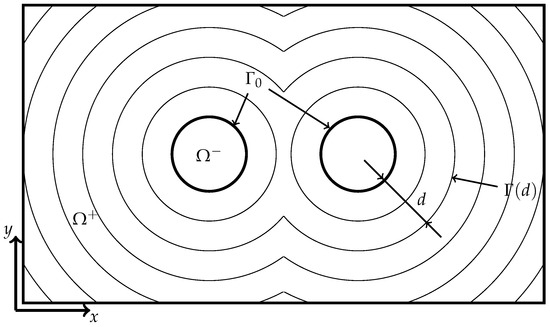
Figure 2.
Diagram of successive burning surface contours over the burn-up of a multiport geometry, with initial interface , burnback distance d, interface at that distance (d), interior region Ω− and exterior region Ω+.
Several burnback simulations to describe the burning process of fuel grains exist. Miller et al. [11], Brooks et al. [12] and Ricciardi [13] describe the burnback analytically for certain two-dimensional geometries. Hartfield et al. [14,15] and Tola and Nikbay [16] give descriptions of further geometries. These analytical descriptions are limited to simple, mostly two-dimensional geometries with a constant spatial regression rate. There is no universal method for arbitrary geometries. Each geometry must be derived and implemented separately. This can be a challenging and time-consuming process, especially for three-dimensional or twisted geometries like the VISERION fuel grain.
Therefore, more general methods were developed by Peterson et al. [17] for the Solid Propellant Rocket Motor Performance Computer Program (SPP) [18,19,20]. A layering technique with predefined base geometries is used. These geometries can be combined by Boolean operations to describe the flow volume of a cylindrical combustion chamber. This technique is more general than the analytical description and can be adapted to new geometries. However, it is a time-consuming process to describe the geometries, limited to the predefined base geometries and only valid for constant spatial regression rates.
Analytical geometry descriptions are useful for simple geometries with constant spatial regression rates. For complex geometries and variable regression rates, numerical methods are needed. The numerical description of geometries is mainly divided into explicit and implicit methods. Explicit methods describe the geometry with a numerical surface grid. The deformation is performed by moving markers on the surface. This works for small deformations. However, convex edges can lead to degenerated cells that are hard to handle.Implicit methods do not underline such restrictions. The geometry is described by an implicit function, often a Signed Distance Function (SDF). Instead of a mesh, the surface is described by an isosurface of the function, usually by the zero isosurface. The deformation is described by the movement of the implicit function with Hamilton–Jacobi equations, especially by the Level Set Method (LSM). This is usually performed on stationary numerical grids.
Several implementations of the LSM for burnback simulations exist.
1.1. Level Set Method
The LSM was first developed by Dervieux and Thomasset [21] and later popularized by Osher and Sethian [22]. It is popular in image processing, computer graphics, computational geometry, optimization, computational fluid dynamics and computational biology. The first known application to burnback simulations was by Yildirim and Aksel [23]. Since then, several implementations have been used for burnback simulations of solid rocket motors: Cavallini [24] used Cartesian and cylinder structured meshes and calculation methods similar to the ones used here. Gontijo and Filho [25] used a two-dimensional LSM on Cartesian grids to analyze hybrid rocket burn-up coupled with a two-phase tank simulation. Funami and Takano [26] analyzed a star-fractal geometry of a hybrid rocket engine with a three-dimensional Cartesian grid LSM. Liu et al. [27] also employed a three-dimensional Cartesian LSM and qualitatively compared their results for a solid rocket motor against CT images. In a recent study, Chao-Fan et al. [28] used the LSM for solid rocket motor burnback simulations.
1.2. Fast Marching Method
The Fast Marching Method (FMM) is a method related to the LSM that does not require temporal integration [29]. It has been used for burnback simulations on unstructured meshes [30]. In recent times, multiple open-source programs for the analysis of solid motor geometries have been made available [31,32]. These use an FMM implementation from scikit-fmm [33] and are therefore limited to Cartesian grids.
1.3. Signed Distance Function
If the regression rate is assumed to be spatially constant, the surface evolution can be simplified to the distance calculation only. This approach has been used in the Rocgrain program by Willcox et al. [34], where the SDF was called a Minimum Distance Function (MDF). Ren et al. [35] used second-order tetrahedral meshes with an improved marching tetrahedron method to approximate the burning surface. These are very similar to the methods described in this paper.
This paper focuses on burnback simulations for calculating the fuel surface and fluid volume for preliminary engine design. The implicit surface tracking method is used to describe the burn-up of arbitrary geometries, assuming spatially constant regression rates. Two calculation methods for each of the output variables are presented and validated using simple geometries with known analytical solutions. Finally, the application on complex, real-world fuel geometries is shown with the fuel geometry of the VISERION engine.
2. Methods
This section explains the implicit surface tracking method using a zero-level-set approach. It also describes the numerical discretization and two methods for calculating the fuel surface area and fluid volume.
2.1. Implicit Surface Tracking
Surface tracking methods divide the considered region into an interior region and an exterior region , separated by the interface . Implicit methods define a function on the whole region and use the zero-level-set as the interface definition. A moving interface can then be described by manipulating . The level set Equation (1) [22] describes the movement of the interface due to an interface velocity in the normal direction F:
where defines the initial position of the interface. To set numerically, a Signed Distance Function (SDF) is used. This is achieved by calculating the signed wall distance to the initial burning surface . The SDF also satisfies , which leads to good numerical behavior near the interface. For homogeneous burn-ups, that is, with spatially constant regression rates , new solutions can be generated by the subtraction of the burnback distance from the initial solution:
With this, the homogeneous burn-up can be reduced to the burnback distance without the need to use specific regression rates. The interface for a specific distance is then described by the zero-level-set .
To consider locally varying regression rates , Equation (1) can be solved directly with the LSM or with the FMM. This will be implemented in a follow-up project.
2.2. Meshing
For spatial discretization of arbitrary geometries, it was decided to use an unstructured, tetrahedral mesh. Therefore, the implementation only has to consider tetrahedral and triangle elements for volume and surface cells, respectively. Mesh generation is performed with the Gmsh software 4.11.1 [36]. This tool allows CAD-generated STEP files of arbitrary geometries to be imported and meshed. This enables the meshing of the grain geometry and the enclosed fluid volume with a conformal boundary as the initial interface between. For the handling of mesh data and coupling to external programs, the DLR FlowSimulator DataManager environment is used [37]. Originally designed to unify flow simulation capabilities with Python APIs, this framework is used here for the extensive import/export capabilities as well as simple data access as NumPy structures [38] for efficient calculations. One of the FlowSimulator plugins FSWallDistance is used to set up the SDF . It calculates the distance of each node in the mesh to the nearest node on the initial interface. After this, the sign in the fluid region is set to negative to create the Signed Distance Function.
2.3. Calculation of Output Values
For preliminary design analysis within AHRES, the fluid volume within the chamber and the burning surface area are used. For both geometry quantities, two calculation methods are implemented and analyzed.
2.3.1. Direct Method
The first method evaluates the SDF directly via a Heaviside function for the fluid volume and the Dirac delta distribution for the surface area calculation [29,39]:
For a first-order approximation, the continuous integrals are evaluated as discrete sums over the N volume cells:
With being the volume of cell i, to generate the required values of on the cell volumes, the values of the nodes are averaged for each cell:
The gradient of the SDF in the calculation of the burning surface area is approximated as the nodes-based Green Gauss gradient with first-order accuracy:
For the numerical evaluation, the Heaviside function and the Dirac delta distribution also have to be approximated. Here, a regularization version based on trigonometric functions is used [39]:
The parameter is set to , where is the specified cell length for meshing with Gmsh.
2.3.2. Interpolation Method
The second method interpolates the explicit position of the interface and calculates the output quantities based on the extracted interface. For this, a variation of the marching tetrahedra algorithm [40] is used. Similar approaches have been used in burnback simulations before [24,30,35]. When extracting the zero-level-set , the nodes on each tetrahedron can be sorted in ascending order of the node values such that . With this, 15 different possibilities of the relative position between the interface and the tetrahedron exist. For the interface extraction, there are 8 relevant intersection versions that are shown in Figure 3.
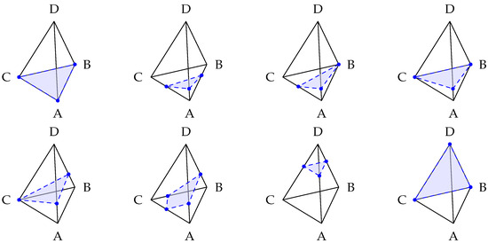
Figure 3.
Interpolation of interface in a tetrahedron with .
After classifying the intersection version, the cell edges with interface intersection are determined. The intersection point of the interface with the cell edge can then be linearly interpolated based on the node values of the SDF. With this, the method is expected to be first-order accurate. From these points, new surface elements describing the interface can be created, and the original volume elements can be split into fluid and solid parts. To retain the tetrahedron-based mesh, the resulting prisms and pyramids are split further into tetrahedrons. Here, care is taken to retain the mesh connectivity of adjacent cells by matching the splitting directions [41].
The calculation of the fluid volume and the burning surface area is then performed by a simple summation of the appropriate cell volumes and cellface areas respectively. Due to the explicit representation generated by this interpolation method, it can also be used to export mesh representations of the volumes and interface at arbitrary times of the burn-up. These meshes can then be used for coupling with other programs, for example, flow simulations.
3. Validation and Results
To validate the implementation and generated results, comparisons to analytical solutions are evaluated. For this, four example geometries are considered. All geometries consist of constant two-dimensional cross sections that are extruded and calculated in three dimensions. To resolve the burn-up process, 200 burnback distances d were evaluated for every calculation.
The first geometry is a Quasi-1D geometry, consisting of two neighboring cubes, see Figure 4a. Both cubes have edge lengths of 1 mm, and the initial interface is the shared surface between these cubes. The second geometry is a cylindrical fuel grain with an external diameter of 100 mm and a port diameter of 30 mm, see Figure 4b. The third geometry is a telescope geometry with an annular chamber, see Figure 4c. The initial port has an inner diameter of 30 mm and an outer diameter of 40 mm. The overall diameter is 100 mm with the length being 30 mm. The final geometry represents a multiport geometry with two cylindrical fuel ports in a rectangular fuel block, see Figure 4d. The ports have initial diameters of 10 mm and are offset by 10 mm from the plane of symmetry. The outer dimensions of the fuel block are 70 mm × 40 mm with a length of 50 mm.
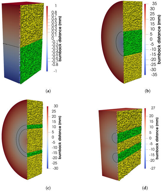
Figure 4.
Validation geometries: (a) Quasi-1D geometry, (b) cylinder geometry, (c) telescope geometry, and (d) multiport geometry. In cut-plane: green—initial fluid volume; yellow—initial fuel volume.
3.1. Convergence
Firstly, the convergence of the methods and implementation for different mesh sizes is analyzed. For this, the error E between the numerical solution and the analytical solution is calculated:
The corresponding order of a method can be calculated from the results of two different cell sizes and . When meshing with Gmsh, the cell size is set, but in the resulting mesh, slightly different sizes can be generated to accommodate the geometry. Therefore, to calculate the observed order of the method, the generated number of volume cells N is used:
To characterize the error over all burnback distances d, two error functions are utilized. The first is the maximum absolute error over all distances :
The second error is an averaged value in the form of the root-mean-square-error over the distances:
Each geometry was evaluated with four different mesh sizes, each step at least halving . This resulted in meshes from 5438 to up to 8.4088 × 10⁶ volume cells.
Figure 5 shows the errors and over different mesh sizes when calculating the fluid volume for each example geometry. In every case, the order of the method is higher than one, so both the direct method using the Heaviside function and the interpolation method converge. The direct method produces smaller errors than the interpolation method, both in terms of maximum errors and average errors . Further, the direct method is of slightly higher order as well, so it should be the preferred method for calculating the fluid volume. When evaluating the maximum errors in the telescope geometry (Figure 5c), an increase in errors over the first mesh refinement is seen. This can be attributed to the very coarse mesh setting, where the cell size is the same as the width of the initial fluid volume (5 mm).
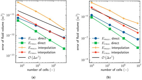
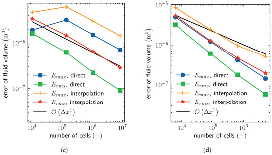
Figure 5.
Convergence of fluid volume calculations: (a) Quasi-1D geometry, (b) cylinder geometry, (c) telescope geometry, and (d) multiport geometry.
Figure 6 shows the errors over different mesh sizes when calculating the burning surface area. Here, the direct method using the Dirac delta function does not converge. Only the averaged error of the multiport geometry has an order of higher than one (Figure 6d), while in some cases the errors stay constant. This non-convergent behavior could be a result of the regularization version of the Dirac distribution, which is known to be lower than first-order in some cases [42]. Even with better approximations of the Dirac distribution, Cavallini [24] found similar problems with this method. Convergence of the interpolation method is considerable better and, except for the Quasi-1D geometry (Figure 6a), can be seen as a first-order method.
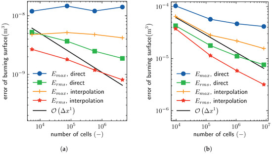
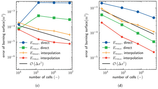
Figure 6.
Convergence of burning area calculations: (a) Quasi-1D geometry, (b) cylinder geometry, (c) telescope geometry, and (d) multiport geometry.
3.2. Accuracy
To evaluate the accuracy of the burnback simulations, the behaviors of the Quasi-1D- and multiport geometries are evaluated and compared to the analytical solutions. Here, the second-finest meshes from the convergence study are used. These contain 580 × 103 and 834 × 103 cells, respectively. For better comparisons between geometries, a relative error is introduced:
The burnback process of the Quasi-1D geometry is shown in Figure 7. The fluid volume and burning surface area both show only small deviations from the exact, analytical solution. Only the area calculation using the direct method has noticeable differences at the minimum and maximum distances of the burnback process. These can be attributed to the Dirac approximation smearing the interface over multiple cells and here, over the geometry edges. Further deviations are at the initial interface in the form of oscillations. These are a result of the imprecise calculation of the distance function by calculating the distance between nodes instead of the interface normal direction. The oscillations are also a cause of the non-convergence discussed previously, as their amplitude does not reduce with further mesh refinement. In the plot of the errors, additional deviations in the fluid volume for small distances d are indicated. These are a result of very small values of the reference quantity in the calculation of the relative error, Equation (15). Overall, the errors are small with typical values being less than 1%. The results from the cylinder- and telescope geometries behave very similarly to the Quasi-1D geometry and can be found in Supplementary Figures S1 and S2.
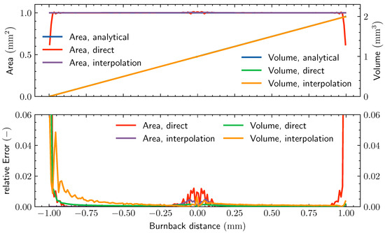
Figure 7.
Burnback behavior of the Quasi-1D geometry and error relative to the analytical solution. Lines of analytical solution (blue) hidden behind the interpolation (purple and orange). Line of direct volume calculation (green) also hidden behind the interpolation (orange).
For the more complex multiport geometry, the burnback behavior is shown in Figure 8. The process can be divided into five phases due to the merging of the ports and splitting into smaller slivers when the burning surface reaches a wall of the geometry. Again, all calculations show good agreement with the analytical result and no visual differences; only the direct calculation of the burning surface area shows differences at the transition between the phases. At these points, where the area is not differentiable, the direct method smears the discontinuity over a larger distance, again due to the regularization. In contrast, the interpolation method can resolve these transitions precisely and shows considerably smaller errors here. While there are no direct differences seen in the volume, the error of the interpolation method is larger by a factor of two to three. When choosing the interpolation method for the burning surface area calculation and the direct method for fluid volume, the results are the most accurate. With this, the error is often smaller than 1% and only approaches 3% at non-differentiable points.
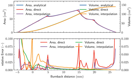
Figure 8.
Burnback behavior of the multiport geometry and error relative to the analytical solution. Lines of analytical solution (blue) hidden behind the interpolation (purple and orange). Line of direct volume calculation (green) also hidden behind the interpolation (orange).
3.3. Application to the VISERION Engine
The VISERION hybrid rocket engine uses a helical geometry for the fuel grain with a length of 800 mm and an outer diameter of 219.5 mm. Because of this complex three-dimensional geometry, no analytical solution is available. To discretize the geometry, a cell size of mm is used, resulting in a mesh with 17.5 million cells. Figure 9a shows the initial interface geometry.
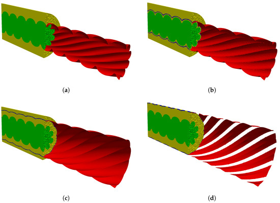
Figure 9.
VISERION burn-up at different burnback distances (a): mm, (b): mm, (c): mm, (d): mm. Green: initial fluid volume, yellow: initial fuel volume, blue: cut cells, red: momentary interface.
The behavior of the burnback process is shown in Figure 10. As from the example geometries expected, both methods demonstrate a strong agreement in volume, with a nearly linear increase from 0 mm to 41 mm, and no visual differences. At a burnback distance of 41 mm, this flattens as the burning surface reaches the outer diameter and the fuel block degrades into slivers. The burning surface area plots also agree between both methods. However, as previously mentioned, the direct methods are unable to resolve non-differentiable points. This is especially obvious at the local maximum at a distance of mm, which is completely missing with the direct method.
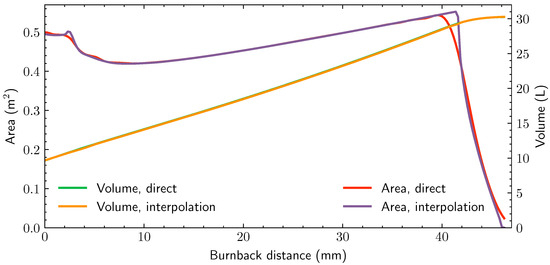
Figure 10.
Burnback of VISERION fuel grain geometry. Line of direct volume calculation (green) hidden behind the interpolation (orange).
In Figure 9, four characteristic points in the burn-up process are shown. These are direct results from the interpolation method extracting the interface and exporting it to a new mesh. The initial condition prior to the burn-up is shown in Figure 9a. The second point at a distance of mm shows a less pronounced geometry with only a marginal increase in port diameter and is near the minimum area during the burn-up, shown in Figure 9b. Figure 9c shows a burnback distance of 25 mm and is characteristic for the main portion of the burn-up from 8.5 mm to 41 mm. Here, the wedges are almost completely burned up and do not increase the area significantly. The final point shows the disintegration of the fuel block into helical slivers, shown in Figure 9d. This is avoided in engine testing to prevent the danger of damage to the chamber walls and problems from slivers breaking off. The complete burn-up process is visualized in Supplementary Video S1.
In the future, these calculations will be directly coupled with the AHRES software to improve internal ballistic calculations for unsteady simulations over the complete burn time.
4. Discussion and Conclusions
In this paper a new burnback simulation for the AHRES software is introduced. Arbitrary, three-dimensional geometries can be automatically meshed and calculated. For this, a SDF is set up as the solution of burn-up with locally constant regression rates. This SDF can also be used as an initial solution for inhomogeneous calculations using LSM or FMM. For this, an extension of the software is planned. It will accept spatially resolved regression rates, calculated by the AHRES software and flow simulations to evolve the interface accordingly.
The fluid volume and the burning surface area are calculated via two methods each. The direct method shows good qualitative results by numerical integration of the SDF and is the preferred method for evaluating the fluid volume. The interpolation method uses a modified marching tetrahedron approach to extract the interface position. It is the preferred method to calculate the burning surface area. In combination, the calculations are characterized as first-order methods and produce small errors of less than 2% for practical mesh resolutions.
The interpolation method also enables the export of numerical meshes at arbitrary points during the burn-up process. In the future, this can be used to couple the burnback simulation with other programs, for example, flow solvers.
Finally, the results from the VISERION geometry are shown. With this, practical application of the software on real, complex three-dimensional geometries is demonstrated.
The software was developed and validated in the context of complex hybrid rocket fuel designs, including multiport designs with changing surface topologies. It can also be used for burnback simulations of solid rocket motors, often using simpler geometries. The underlying implicit method is a general surface-tracking method and can therefore be used for other problems involving moving surfaces. In the context of hybrid rocket engines, this could be ablative components in the form of heat shields or rocket nozzles, for example.
Supplementary Materials
The following supporting information can be downloaded at: https://www.mdpi.com/article/10.3390/aerospace11020103/s1, Figure S1: Burnback behavior of the cylinder geometry and error relative to analytical solution; Figure S2: Burnback behavior of the telescope geometry and error relative to analytical solution; Video S1: Complete burn-up Process of the Viserion—Geometry.
Author Contributions
Conceptualization, J.M.; methodology, J.E.Z. and J.M.; software, J.E.Z.; validation, J.E.Z.; formal analysis, J.E.Z.; investigation, J.E.Z.; resources, J.M.; data curation, J.E.Z.; writing—original draft preparation, J.E.Z. and J.M.; writing—review and editing, J.E.Z., J.M. and V.W.; visualization, J.E.Z.; supervision, V.W.; project administration, V.W.; funding acquisition, V.W. All authors have read and agreed to the published version of the manuscript.
Funding
This research received no external funding.
Data Availability Statement
Data are unavailable due to privacy.
Conflicts of Interest
The authors declare no conflicts of interest. The funders had no role in the design of the study; in the collection, analyses, or interpretation of data; in the writing of the manuscript; or in the decision to publish the results.
Abbreviations
The following abbreviations are used in this manuscript:
| AHRES | Advanced Hybrid Rocket Engine Simulation |
| ALDUINA | Advanced Lithergol Demonstrator Unit for Increased Altitudes |
| ARIEL | ATEK Hybrid Rocket Engine Laboratory device |
| DLR | German Aerospace Center |
| FMM | Fast Marching Method |
| HTPB | Hydroxyl-terminated Polybutadiene |
| LSM | Level Set Method |
| MDF | Minimum Distance Function |
| SDF | Signed Distance Function |
| SPP | Solid Propellant Rocket Motor Performance Computer Program |
| TAU | Triangular Adaptive Upwind |
References
- Božić, O.; Porrmann, D.; Lancelle, D.; Hartwig, A. Program AHRES and its Contribution to Assess Features and Current Limitations of Hybrid Rocket Propulsion. In Proceedings of the 63rd International Astronautical Congress, Naples, Italy, 1–5 October 2012. [Google Scholar]
- Schwamborn, D.; Gerhold, T.; Heinrich, R. The DLR TAU-code: Recent applications in research and industry. In Proceedings of the European Conference on Computational Fluid Dynamics, Egmond aan Zee, The Netherlands, 5–8 September 2006. [Google Scholar]
- May, S.; Božić, O. CFD Simulation of Chemical Non-Equilibrium Reacting Flow within the AHRES Hybrid Rocket Engine. In Proceedings of the 6th European Conference for Aeronautics and Space Sciences, Kraków, Poland, 29 June–3 July 2015. [Google Scholar]
- May, S.; Božić, O. Numerical Simulation of the Flow and Combustion Inside the Reaction Chamber of the AHRES Hybrid Rocket Engine. In Notes on Numerical Fluid Mechanics and Multidisciplinary Design; Springer International Publishing: Cham, Switzerland, 2016; pp. 801–809. [Google Scholar] [CrossRef]
- May, S.; Karl, S.; Božić, O. Development of an Eddy Dissipation Model for the use in Numerical Hybrid Rocket Engine Combustion Simulation. In Proceedings of the 7th European Conference for Aeronautics and Space Sciences, Milano, Italy, 3–6 July 2017. [Google Scholar] [CrossRef]
- Poppe, G.; May, S.; Bierwagen, N.M.; Eggers, T. The Site Trauen of the German Aerospace Center - Past, Present and Future of the Largest Test Site for Rocket Engines in Germany. In Proceedings of the 3rd Ground-Based Space Facilities Symposium, Marseille, France, 6–8 December 2022. [Google Scholar]
- Viserion Press Release. Available online: https://www.dlr.de/en/latest/news/2021/03/20210719_hybrid-rocket-engine-viserion-successfully-tested (accessed on 1 October 2023).
- Dabanović, A.; Martin, J.; May, S.; Eggers, T. Design of a sounding rocket upper stage based on the hybrid rocket engine VISERION. CEAS Space J. 2022, 15, 467–476. [Google Scholar] [CrossRef]
- Poppe, G.; Bozic, O.; May, S.; Bierwagen, N.M. Characterization of Regression Rate and Combustion Process in a High-Pressure 2D Hybrid Rocket Engine with Optical Access. In Proceedings of the International Astronautical Congress, IAC, Bremen, Germany, 1–5 October 2018. [Google Scholar]
- Glaser, C.; Hijlkema, J.; Anthoine, J. Evaluation of Regression Rate Enhancing Concepts and Techniques for Hybrid Rocket Engines. Aerotec. Missili Spaz. 2022, 101, 267–292. [Google Scholar] [CrossRef]
- Miller, W.H.; Douglass, H.W.; Collins, J.H.; Keller, R.B., Jr. Solid Rocket Motor Performance Analysis and Prediction; Techreport NASA-SP-8039; National Aeronautics and Space Administration, Lewis Research Center: Cleveland, OH, USA, 1971. [Google Scholar]
- Brooks, W.T.; Douglass, H.W.; Collins, J.H.; Keller, R.B., Jr. Solid Propellant Grain Design and Internal Ballistics; Techreport NASA-SP-8076; National Aeronautics and Space Administration, Lewis Research Center: Cleveland, OH, USA, 1972. [Google Scholar]
- Ricciardi, A. Generalized geometric analysis of right circular cylindrical star perforated and tapered grains. J. Propuls. Power 1992, 8, 51–58. [Google Scholar] [CrossRef]
- Hartfield, R.; Jenkins, R.; Burkhalter, J.; Foster, W. A Review of Analytical Methods for Solid Rocket Motor Grain Analysis. In Proceedings of the 39th AIAA/ASME/SAE/ASEE Joint Propulsion Conference & Exhibit, Huntsville, AL, USA, 20–23 July 2003; American Institute of Aeronautics and Astronautics: Reston, VA, USA, 2003. [Google Scholar] [CrossRef]
- Hartfield, R.; Jenkins, R.; Burkhalter, J.; Foster, W. Analytical Methods for Predicting Grain Regression in Tactical Solid-Rocket Motors. J. Spacecr. Rocket. 2004, 41, 689–693. [Google Scholar] [CrossRef]
- Tola, C.; Nikbay, M. Internal Ballistic Modeling of a Solid Rocket Motor by Analytical Burnback Analysis. J. Spacecr. Rocket. 2019, 56, 498–516. [Google Scholar] [CrossRef]
- Peterson, E.C.; Nielsen, C.C.; Johnson, W.C.; Cook, K.; Barron, J.G. Generalized coordinate grain design and internal ballistics evaluation program. In Proceedings of the 3rd Solid Propulsion Conference, Atlantic City, NJ, USA, 4–6 June 1968; American Institute of Aeronautics and Astronautics: Reston, VA, USA, 1968. [Google Scholar] [CrossRef]
- Coats, D.E.; Levine, J.N.; Cohen, N.S.; Nickerson, G.R.; Tyson, T.J. A Computer Program for the Prediction of Solid Propellant Rocket Motor Performance; Techreport ADA015140; Air Force Rocket Propulsion Laboratory, Airforce Systems Command: Edwards, CA, USA, 1975; Volume 1. [Google Scholar]
- Coats, D.E.; Levine, J.N.; Cohen, N.S.; Nickerson, G.R.; Tyson, T.J. A Computer Program for the Prediction of Solid Propellant Rocket Motor Performance; Techreport ADA015141; Air Force Rocket Propulsion Laboratory, Airforce Systems Command: Edwards, CA, USA, 1975; Volume 2. [Google Scholar]
- Coats, D.E.; Levine, J.N.; Cohen, N.S.; Nickerson, G.R.; Tyson, T.J. A Computer Program for the Prediction of Solid Propellant Rocket Motor Performance; Techreport ADA022880; Air Force Rocket Propulsion Laboratory, Airforce Systems Command: Edwards, CA, USA, 1975; Volume 3. [Google Scholar]
- Dervieux, A.; Thomasset, F. A finite element method for the simulation of a Rayleigh-Taylor instability. In Lecture Notes in Mathematics; Springer: Berlin/Heidelberg, Germany, 1980; pp. 145–158. [Google Scholar] [CrossRef]
- Osher, S.; Sethian, J.A. Fronts propagating with curvature-dependent speed: Algorithms based on Hamilton-Jacobi formulations. J. Comput. Phys. 1988, 79, 12–49. [Google Scholar] [CrossRef]
- Yildirim, C.; Aksel, H. Numerical Simulation of the Grain Burnback in Solid Propellant Rocket Motor. In Proceedings of the 41st AIAA/ASME/SAE/ASEE Joint Propulsion Conference & Exhibit, Tuscon, AZ, USA, 10–13 July 2005. [Google Scholar] [CrossRef]
- Cavallini, E. Modeling and Numerical Simulation of Solid Rocket Motors Internal Ballistics. Ph.D. Thesis, Sapienza Università di Roma, Rome, Italy, 2010. [Google Scholar]
- Gontijo, M.; Filho, R. Two-Phase Tank Emptying and Burnback Coupled Internal Ballistics Prediction on Hybrid Rocket Motors. In Engenharias: Metodologias e Práticas de Caráter Multidisciplinar 3; Atena Editora: Ponta Grossa, PR, Brasil, 2021; pp. 46–56. [Google Scholar] [CrossRef]
- Funami, Y.; Takano, A. Regression-Rate Evaluation of Hybrid-Rocket Fuel Grain with a Star-Fractal Swirl Port. Trans. Jpn. Soc. Aeronaut. Space Sci. 2023, 66, 61–69. [Google Scholar] [CrossRef]
- Liu, S.; Lu, H.; Zhang, B.; Yang, Y.; Sang, D. Study on Burning Surface Regression Algorithm under Erosive Burning Based on CT Images of Solid Rocket Motor Grain. Aerospace 2023, 10, 21. [Google Scholar] [CrossRef]
- Han, C.-H.; Xu, J.-S.; Wang, S.-H. Solid Rocket Motor Propellant Grain Burnback Simulation Based on Level Set Method. J. Phys. Conf. Ser. 2023, 2478, 112010. [Google Scholar] [CrossRef]
- Sethian, J.A. Level Set Methods and Fast Marching Methods—Evolving Interfaces in Computational Geometry, Fluid Mechanics, Computer Vision, and Materials Science; Cambridge University Press: Cambridge, UK, 1999. [Google Scholar]
- Toker, K.A.; Aksel, H.; Tinaztepe, T. 3-dimensional propellant grain burnback calculations on tetrahedron mesh by fast marching method. In Proceedings of the 22nd Applied Aerodynamics Conference and Exhibit, Providence, RI, USA, 16–19 August 2004; p. 4960. [Google Scholar] [CrossRef]
- Reilley, A. openMotor. 2023. Available online: https://github.com/reilleya/openMotor (accessed on 1 October 2023).
- Jupiter, P. SolidPy. 2023. Available online: https://github.com/Projeto-Jupiter/SolidPy (accessed on 1 October 2023).
- Furtney, J. scikit-fmm: The Fast Marching Method for Python. 2023. Available online: https://github.com/scikit-fmm/scikit-fmm (accessed on 1 October 2023).
- Willcox, M.A.; Brewster, M.Q.; Tang, K.C.; Stewart, D.S. Solid Propellant Grain Design and Burnback Simulation Using a Minimum Distance Function. J. Propuls. Power 2007, 23, 465–475. [Google Scholar] [CrossRef]
- Ren, P.; Wang, H.; Zhou, G.; Li, J.; Cai, Q.; Yu, J.; Yuan, Y. Solid rocket motor propellant grain burnback simulation based on fast minimum distance function calculation and improved marching tetrahedron method. Chin. J. Aeronaut. 2021, 34, 208–224. [Google Scholar] [CrossRef]
- Geuzaine, C.; Remacle, J.F. Gmsh: A 3-D finite element mesh generator with built-in pre- and post-processing facilities. Int. J. Numer. Methods Eng. 2009, 79, 1309–1331. [Google Scholar] [CrossRef]
- Huismann, I.; Reimer, L.; Strobl, S.; Eichstädt, J.R.; Tschüter, R.; Rempke, A.; Einarsson, G. Accelerating the FlowSimulator: Profiling and scalability analysis of an industrial-grade CFD-CSM toolchain. In Proceedings of the 9th Edition of the International Conference on Computational Methods for Coupled Problems in Science and Engineering (COUPLED PROBLEMS 2021), Sardinia, Italy, 13–16 June 2021. [Google Scholar] [CrossRef]
- Harris, C.R.; Millman, K.J.; van der Walt, S.J.; Gommers, R.; Virtanen, P.; Cournapeau, D.; Wieser, E.; Taylor, J.; Berg, S.; Smith, N.J.; et al. Array programming with NumPy. Nature 2020, 585, 357–362. [Google Scholar] [CrossRef] [PubMed]
- Zhao, H.K.; Chan, T.; Merriman, B.; Osher, S. A Variational Level Set Approach to Multiphase Motion. J. Comput. Phys. 1996, 127, 179–195. [Google Scholar] [CrossRef]
- Doi, A.; Koide, A. An Efficient Method of Triangulating Equi-Valued Surfaces by Using Tetrahedral Cells. IEICE Trans. Inf. Syst. 1991, 74, 214–224. [Google Scholar]
- Max, N.L.; Williams, P.L.; Silva, C.T. Approximate Volume Rendering for Curvilinear and Unstructured Grids by Hardware-Assisted Polyhedron Projection. Int. J. Imaging Syst. Technol. 2000, 11, 53–61. [Google Scholar] [CrossRef]
- Tornberg, A.K.; Engquist, B. Numerical approximations of singular source terms in differential equations. J. Comput. Phys. 2004, 200, 462–488. [Google Scholar] [CrossRef]
Disclaimer/Publisher’s Note: The statements, opinions and data contained in all publications are solely those of the individual author(s) and contributor(s) and not of MDPI and/or the editor(s). MDPI and/or the editor(s) disclaim responsibility for any injury to people or property resulting from any ideas, methods, instructions or products referred to in the content. |
© 2024 by the authors. Licensee MDPI, Basel, Switzerland. This article is an open access article distributed under the terms and conditions of the Creative Commons Attribution (CC BY) license (https://creativecommons.org/licenses/by/4.0/).