Article

Regression Rate and Combustion Efficiency of Composite Hybrid Rocket Grains Based on Modular Fuel Units

1
School of Environment and Safety Engineering, North University of China, Taiyuan 030051, China
2
State Key Laboratory of High Temperature Gas Dynamics, Chinese Academy of Sciences, Beijing 100190, China
3
School of Engineering Science, University of Chinese Academy of Sciences, Beijing 100049, China
*
Authors to whom correspondence should be addressed.
Aerospace 2024, 11(4), 262; https://doi.org/10.3390/aerospace11040262
Submission received: 21 February 2024 / Revised: 21 March 2024 / Accepted: 26 March 2024 / Published: 28 March 2024
(This article belongs to the Special Issue Hybrid Rocket Engines)

Abstract

:
This study investigated combustion characteristics of composite fuel grains designed based on a modular fuel unit strategy. The modular fuel unit comprised a periodical helical structure with nine acrylonitrile–butadiene–styrene helical blades. A paraffin-based fuel was embedded between adjacent blades. Two modifications of the helical structure framework were researched. One mirrored the helical blades, and the other periodically extended the helical blades by perforation. A laboratory-scale hybrid rocket engine was used to investigate combustion characteristics of the fuel grains at an oxygen mass flux of 2.1–6.0 g/(s·cm2). Compared with the composite fuel grain with periodically extended helical blades, the modified composite fuel grains exhibited higher regression rates and a faster rise of regression rates as the oxygen mass flux increased. At an oxygen mass flux of 6.0 g/(s·cm2), the regression rate of the composite fuel grains with perforation and mirrored helical blades increased by 8.0% and 14.1%, respectively. The oxygen-to-fuel distribution of the composite fuel grain with mirrored helical blades was more concentrated, and its combustion efficiency was stable. Flame structure characteristics in the combustion chamber were visualized using a radiation imaging technique. A rapid increase in flame thickness of the composite fuel grains based on the modular unit was observed, which was consistent with their high regression rates. A simplified numerical simulation was carried out to elucidate the mechanism of the modified modular units on performance enhancement of the composite hybrid rocket grains.

1. Introduction

The hybrid rocket engine (HRE) is progressively emerging as a compelling propulsion system with significant potential for development and commercial viability [1,2,3,4,5]. In comparison with conventional liquid or solid rocket engines, the HRE offers the benefits of adjustable thrust, enhanced safety protocols, environmental friendliness, ease of repeated ignition, and low manufacturing cost [6,7,8,9]. However, the following issues with HRE are still unresolved: the different phases of the propellants and the diffuse combustion characteristics result in the low combustion efficiency of fuel grains [10,11,12,13]. Both low regression rates and oxygen-to-fuel ratio shift will affect engine performance, and proper regression rates can reduce oxygen-to-fuel ratio shift [14]. Therefore, research has focused on improving the regression rates. The use of complex single-port structures and multi-port fuel grains have proven effective in increasing regression rates of fuel grains [15,16,17,18,19,20]. At a constant oxygen mass flow rate, there is an antagonism between the rise rate of regression and enhancement of flux enhancement, which often involves employing multi-port structures to augment the burning surface. This carries certain risks, such as the collapse of adjacent ports caused by the increased volumetric load [12,21]. For this reason, it is more attractive to use a modified single port to improve the fuel grains and resulting turbulence to increase the regression rate [22]. Typically, the work of Kumar et al. [23,24] showed that the use of protrusion and bluff bodies in the single port fuel grain significantly improved the combustion efficiency and regression rate of the engine.
In recent years, three-dimensional (3D) printing technology has become sufficiently developed and successfully applied to the manufacturing of hybrid rocket fuel grains [25,26,27,28,29,30,31,32]. This technique allows for direct integral molding of polymeric fuel grains with a complex single port, which is difficult to accomplish using traditional manufacturing methods [25]. Representative work was published by Whitmore et al. [26,27], who printed a spiral single-port acrylonitrile–butadiene–styrene (ABS) fuel grain in one piece. Centrifugal swirl flow, induced by the helical port, promoted convective heat transfer and increased the regression rates. Another strategy for applying 3D printing to fuel grains has been to embed the printed skeleton reinforcement structure in paraffin-based fuels. Paraffin-based fuels have gained significant attention due to their high regression rates, despite their poor mechanical properties. Embedding 3D printed skeletons, such as the “armored grain” proposed by Bisin et al. [28,29], enhanced the mechanical properties of the paraffin-based grains at the expense of regression rate. In the work of our group, both mechanical properties as well as the regression rate of paraffin-based fuels with embedded ABS helical structure framework proposed by Wang et al. [30] were significantly improved. Varying regression rates of fuels generate groove structures that facilitate oxidant vortex flow to improve turbulence and combustion efficiency. Lin et al. [31,32] subsequently modified the helical structure framework by perforation and used metallic materials to strengthen the mechanical properties and combustion characteristics of the fuel grains. These studies validated the potential of embedded skeletal reinforcement.
Single-port stepped fuel grains with adjustable internal ballistics were recently investigated by Glaser et al. [33,34]. Their design is similar to the stacking of multiple fuel grains, each of which is a separate single-port paraffin-based grain. Flexible modification of multiple single-port paraffin-based grains, and controlling their inner diameter and length to obtain the desired ballistic design within the fuel grains, improves engine performance. However, the stacking may cause interface instability and requires a complicated manufacturing process. Owing to the above-mentioned issues, integrally molded skeleton reinforcement structures produced by 3D printing could be expected to simplify the manufacturing process of fuel grains and enable targeted improvements in HRE.
This study proposed a modular fuel design strategy that can modify the engine combustion. A periodic helical structure framework is the smallest unit of the modular unit. The modular fuel unit comprises a periodical helical structure framework that can be flexibly regulated and integrated by 3D printing. A paraffin-based fuel was embedded in the framework. Two modifications of the helical structure framework were investigated. One was mirroring the helical structure (MS grain); the other was the periodic extension of the helical structure with perforations (PS grain). A fuel grain with periodically extended helical structure (HS grain) and paraffin-based grain (PP grain) were tested for comparison. In the tests, the mass flow rate of oxygen was 9.5–28.1 g/s, corresponding to a mass flux of 2.1–6.0 g/(s·cm2). The combustion chamber pressure, oxygen-to-fuel ratio (O/F) distribution, regression rate, and combustion efficiency of the engines were studied. Radiation imaging was used to analyze the characteristic flame structure in the combustion chamber during the experiments. Simplified 3D simulations were carried out to reveal the mechanism of the modified modular units on performance enhancement of the HRE.

2. Materials and Methods

2.1. Modular Unit Framework

A nested framework is an important support part of the modular fuel unit. As shown in Figure 1, a periodic helical structure framework is the smallest unit of the modular framework that can be flexibly regulated and integrated by 3D printing. The modular unit framework was periodically extended from the helical structural of the smallest unit and consisted of nine 1.5-mm-thick blades with axial helical extension and a 2-mm-thick outer wall. The helical pitch of the blades was 100 mm with 0.5 turns. The length of the modular fuel unit was 50 mm, which was half the length of the manufactured fuel grain. Its outer and inner diameters were 60 mm and 20 mm, respectively. The blades and outer wall were integrally manufactured.
Three composite fuel grains based on the modular unit were studied. The structure of the HS grain was a periodically extended modular unit framework with one periodic expansion. The PS grain improved the helical blades based on the HS grain. There were numerous pores spread over the helical blades of the PS grain, which enhanced adhesion of the paraffin-based fuel to the helical blades. The perforations were carried out along the path of a screw thread rotating in the opposite direction to that of the helical blades, with a pitch of 25 mm. The pores had a diameter of 1 mm and were spaced 2 mm apart. The MS grain design adjusted the helical direction of the helical blades. The structure of the MS grain was obtained by mirroring the helical blades along one end face of the modular unit framework. This particular mirror structure is used to explore the impact of the modular unit design strategy.
Manufacturing of the composite fuel grains comprised two main steps. The first was to print out the designed structure using a commercially available 3D printer (Raiser 3D, Pro2 Plus, Bakersfield, CA, USA). The second was embedding the paraffin-based fuel by means of centrifugal casting technology. Details of the fabrication of the composite columns can be found in previous studies [30].

2.2. Laboratory-Scale Hybrid Rocket Engine

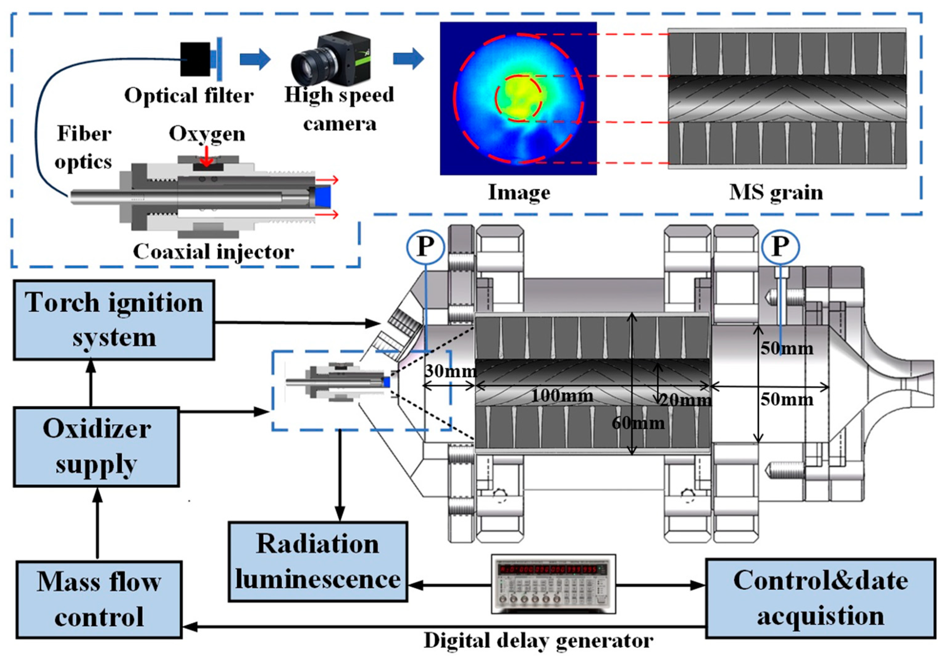
A schematic of the laboratory-scale HRE is shown in Figure 2. The engine consisted of two combustion chambers at the head and tail of the engine, and a main combustion chamber and a laval nozzle with 5 mm throat diameter. The pre- and post-combustion chambers had lengths of 30 mm and 50 mm, respectively, and shared the same diameter of 50 mm. The dimensions of the main combustion chamber correspond to that of the fuel grains. Interfaces were provided in the combustion chambers to connect pressure sensors. Further details can be found in our previous studies [30,35]. The engine was ignited by a torch-type igniter activated by gaseous methane and oxygen. Oxygen from the combustion chamber entered through the annular port of the coaxial injector at an average oxygen mass flow rate of 9.5 to 28.1 g/s. A mass flow controller (Bronkhorst, model F-203AV, Ruurslo, The Netherlands) was used to regulate the oxygen mass flow rate. The coaxial core section of the injector was a fiber optic viewport, which was connected via fiber optics to a high-speed camera (iX Cameras, i-Speed 220, London, UK) and acted as a carrier of radiation luminescence. The frame rate of the camera was 1 kHz and its exposure time was 0.28 ms. A narrowband filter was used to eliminate optical signal clutter. The narrowband filter had a center wavelength of 430 nm and a bandwidth of 10 nm. A digital delay generator (Stanford Research Systems, DG645, Sunnyvale, CA, USA) was connected between the high-speed camera and host computer to provide precise signal pulses and stable trigger times for the camera.

3. Results and Discussion

Table 1 lists the recorded results of fifty experiments, pertaining to average oxygen mass flow rate, m ˙ o , average oxygen mass flux, Gox, average chamber pressure, P ¯ , regression rate, r ˙ , and O/F. These values were calculated as weight averages.

3.1. Combustion Chamber Pressure

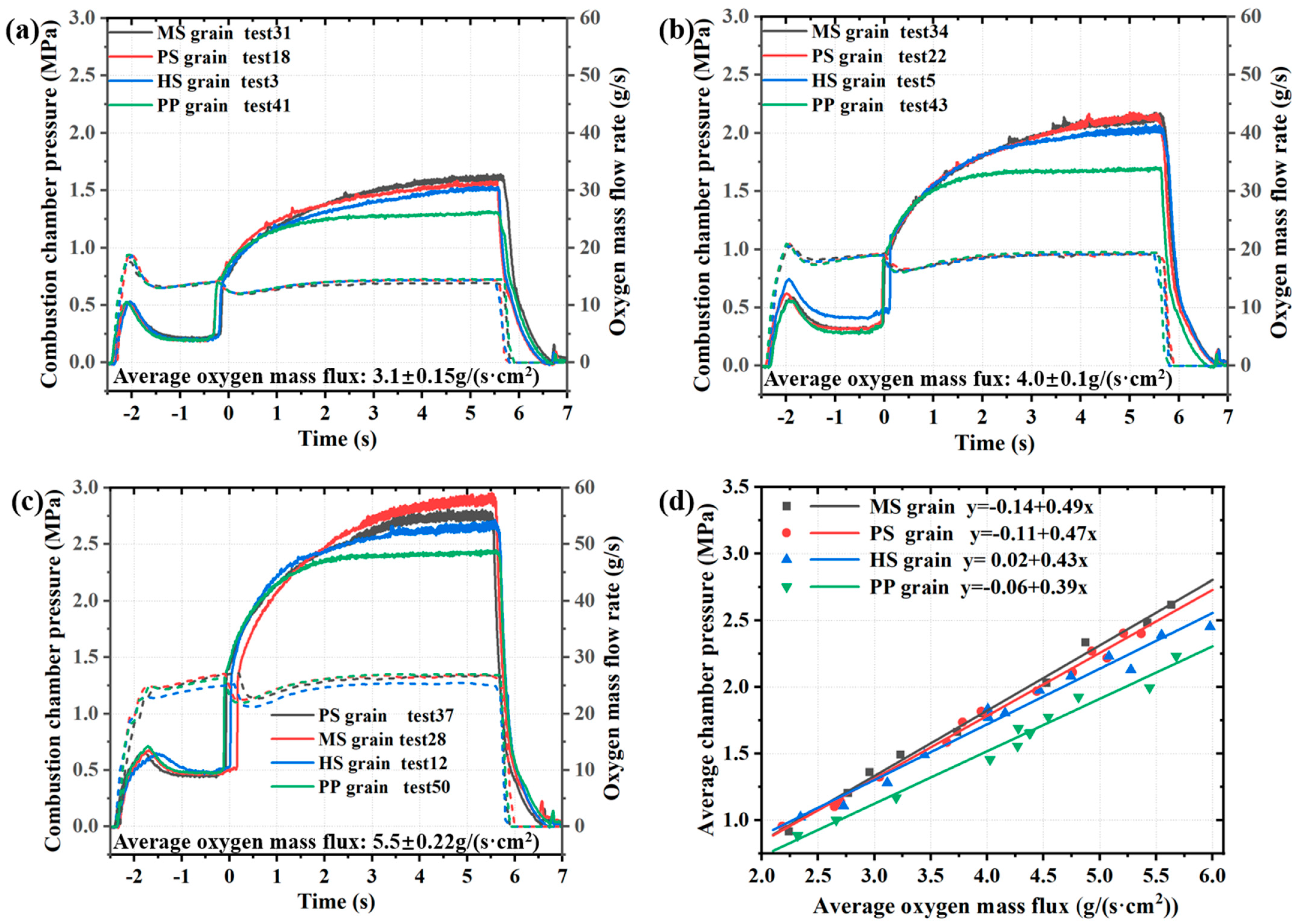
The chamber pressure can reflect the operating status of the engine [36]. Figure 3 provides the histories of the chamber pressure and oxygen mass flow rate with time for the four fuel grain designs under three average oxygen mass fluxes, and the distribution of the average chamber pressures at different oxygen mass fluxes. The ignition time of the engine was defined as the zero point. Differences in ignition times between fuel grains are due to valve switching delays. The entire ignition process lasted approximately 6 s. As the pressure stabilized, the oxygen flow rate stabilized. The variation in chamber pressure was similar for all fuel grains. The chamber pressure of the composite fuel grains was significantly higher than that of the pure paraffin-based grain, which is consistent with the previous conclusions of our group [31]. The pressure in the combustion chamber increased when composite fuel grains consisted of regulated modular units. The combustion chamber pressures of the MS and PS grains were higher than the chamber pressures of the HS grain.

3.2. Regression Rate and Combustion Efficiency

As an important parameter for HRE, regression rate is generally determined by measuring the mass of the grain before and after testing, using the following expression:
r ˙ = d f d 0 2 t = d 0 2 + 4 ( m 0 m f ) π ρ L d 0 2 t
where d f , d 0 refer to the inner diameter of the fuel grains before and after combustion, respectively. m f , m 0 refer to the mass of the fuel grains before and after combustion. ρ refers to the density of fuel, L refers to the length of fuel grains, and t refers to the actual time of engine operation. This value r ˙ can be represented as a function of G O X :
r ˙ = a G O X n
where r ˙   denotes the regression of composite grains, Gox refers to the mass flux of the oxidizer, and a and n refer to the constants obtained by fitting.
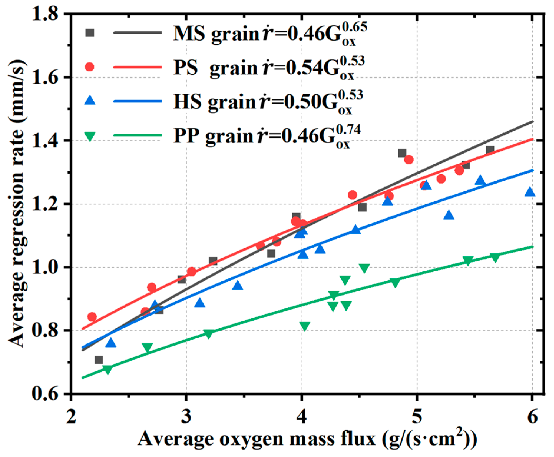
Figure 4 illustrates the distribution of regression rates and their fitting results. Modified composite grains exhibited higher regression rates compared to paraffin-based fuel. The different modifications of the helical structure also different degrees of increase in the regression rates. At the lowest oxygen mass flux, the regression rate of the PS grain was significantly higher than that of the HS grain, while those of the HS and MS grains were similar. However, as the oxygen mass flux increased, the regression rate of the MS grain with the modified modular fuel unit significantly increased, and the rise rate was higher than that of the conventional HS grain. At an average oxygen mass flux of 6.0 g/(s·cm2), the regression rate of the PS grain was consistently 8.0% and 30.7% higher than that of the HS and PP grains, respectively. Similarly, at corresponding positions, the MS grain was 14.1% and 38.1% higher than those of the HS and PP grains, respectively. The high regression rates of two modified composite grains may be due to turbulence enhancement resulting from the designs of the helical structure frameworks.
Characteristic velocity is another key parameter of HRE. Combustion efficiency is expressed by:
η = C e C t
where C t denotes the theoretical characteristic velocity of pure paraffin calculated by the Chemical Equilibrium with Applications software (CEA) [37]. C e denotes the experimentally obtained characteristic velocity:
C e = P ¯ A m ¯ f + m ¯ g
where   P ¯   denotes the average value of the chamber pressure, A denotes the throat area of the nozzle, which is considered to be constant due to small variations, and m ¯ f ,     m ¯ g denote the average mass flow rates of the oxidizer and fuel, respectively.
Figure 5 shows the characteristic velocity distributions of the four fuel grains and their O/F as a function of average oxygen mass flux. The combustion efficiency was significantly improved by the modular design and modifications of the helical structure. The combustion efficiencies of the modified fuels were more concentrated than the paraffin-based grain. The MS grain exhibited higher characteristic velocities and combustion efficiencies, and demonstrated smaller fluctuations of these values across a wide range of average oxygen mass fluxes, compared with the HS grain. The characteristic velocity of the PS grains did not exhibit a notable increase, possibly attributed to the significant increase in regression rate, which reduced the corresponding O/F value. In practical applications, over-dispersion of the O/F will increase the launching cost of the rocket [38]. Figure 5b shows that the O/F of the MS grain changed less compared with other fuel grains for the same average oxygen mass flux. Combined with the above analysis of regression rates, these results show that the increase in regression rate can inhibit changes in the O/F ratio.

3.3. Radiation Luminescence

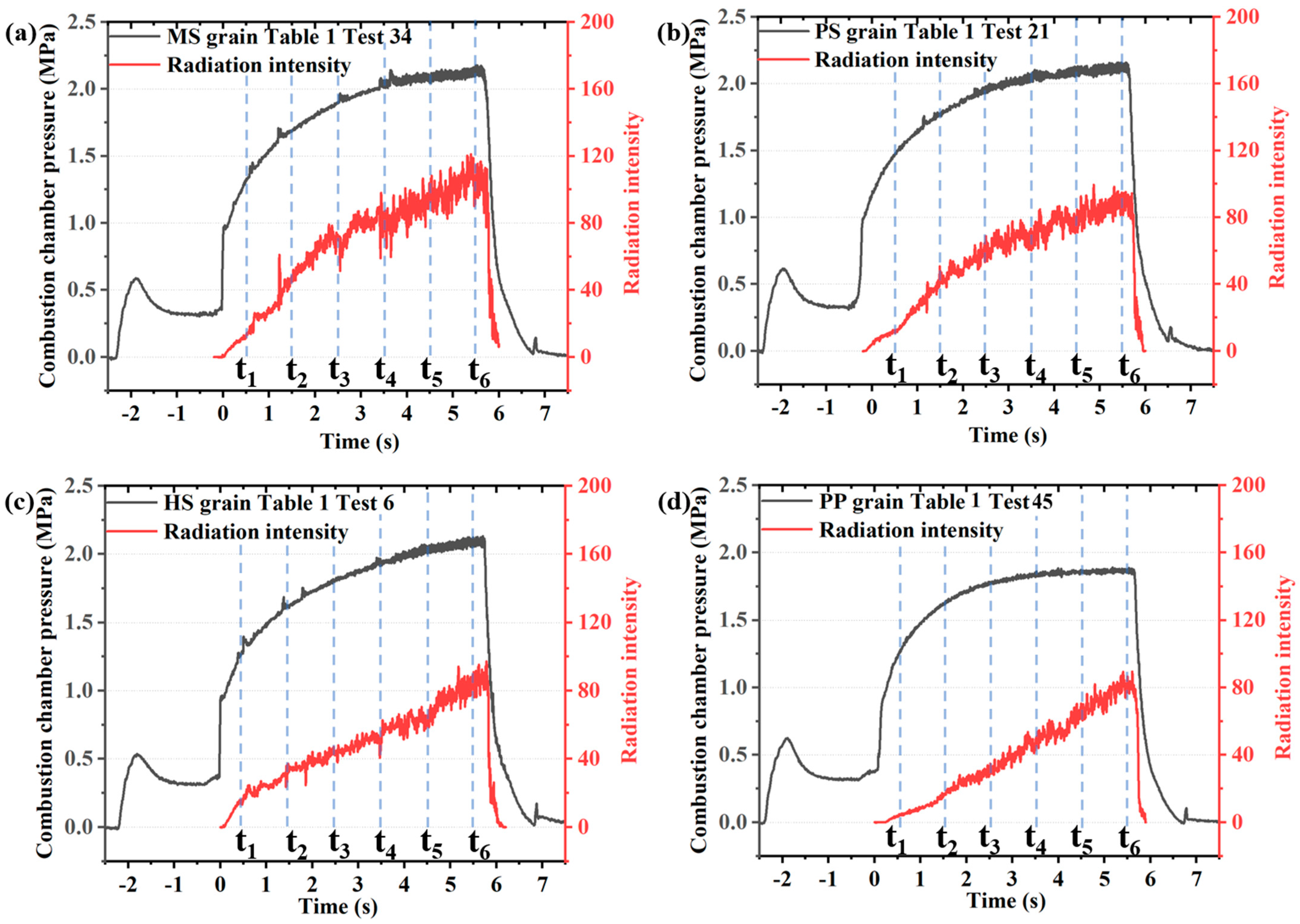
Figure 6 plots the radiation luminescence intensity curves of the different fuel grains and corresponding pressure changes. The average mass flow rate of the oxidant was 18.5 g/s. The radiative intensity used in this study was based on the average pixel value of each frame from the visual area of initial grayscale images, arranged in chronological order according to the capture time. Following ignition, the combustion chamber pressures and radiation intensities of all engines rose at the same time. The combustion chamber pressure reached a steady state first. The upward trend of radiation intensity did not weaken, which may be caused by flame propagation to the pre-combustion chamber, resulting in a larger flame area in the field of view, until the supply of oxidizer was stopped, at which point both the combustion chamber pressure and radiation intensity were reduced to zero. These experiments showed that the composite fuel grains with the modified modular fuel units had higher radiative intensity than the paraffin-based grain.
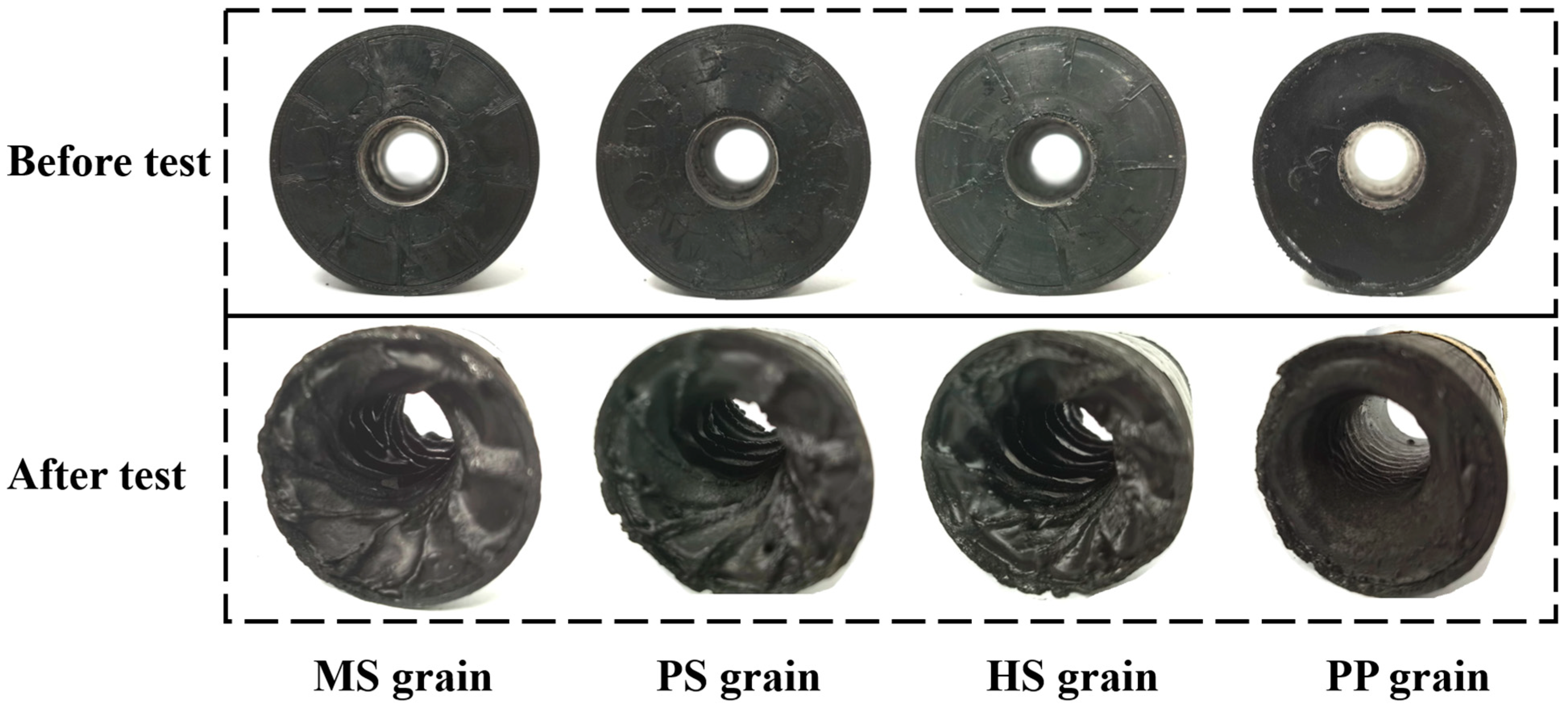
Figure 7 shows the four grains of Figure 6 before and after firing. Prior to combustion, the inner surfaces of all grains were smooth and flat. However, after combustion, a distinct difference can be observed. While the surface of the paraffin-based grain remains flat, the inner surfaces of the other composite grains exhibit prominent grooves. These helical grooves played a crucial role during the combustion process by continuously inducing oxidizer swirl. The presence of these grooves post-combustion highlights their significance in optimizing the performance of composite fuel grains.
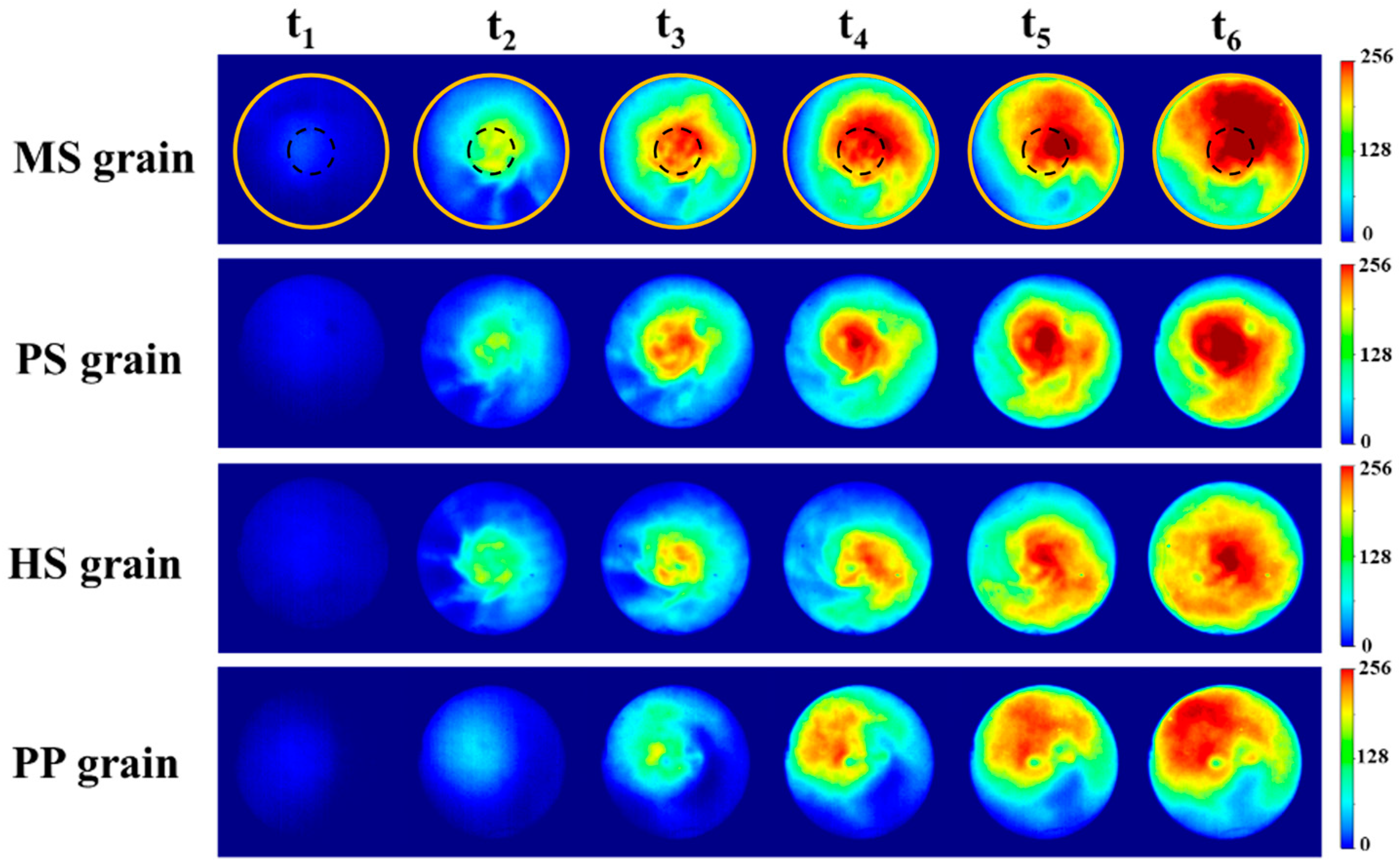
Images capturing the flame within the chamber were obtained to examine alterations in the flame behavior. Values of t1–t6 correspond to 0.5–5.5 s after engine ignition in Figure 6 with an interval of 1 s. Twenty-five images before and after the six times values were selected in turn, and the average gray values of the pixels were determined. Pseudo-color processing results after overall averaging are shown in Figure 8.
The average images of the various fuel grains at different reaction times exhibit similar characteristics. During the initial stage of the reaction (t2, t3), the flame primarily accumulated in the center of the image. As the burning surface increased, flame diffusion and propagation were further enhanced until the flame penetrated the entire combustion chamber and occupied the entire sight window. At t5 and t6, when the combustion chamber pressure had stabilized, the images indicate that the flames in the combustion chamber continued to develop. This observation is consistent with the analysis of radiation intensity. The PP grain exhibited a slower rate of flame development and smaller flame coverage area compared with the composite fuel grains. Additionally, the composite fuel grains produced an obvious filamentous flame structure that was caused by swirling during the combustion process. The average flame images indicate that the composite fuel grains with modified helical structures facilitated flame development. The MS grain exhibited the fastest flame development and thickest flame due to turbulence enhancement. The periodically extended helical structure with perforations increased the swirling flow of the flame and the flame distribution of the PS grain was more concentrated.
The pulsation characteristics of the flame in the combustion chamber were analyzed using proper orthogonal decomposition (POD) [39]. This process of POD is used to transform a sequence of image datasets into a set of linearly uncorrelated variables (modes) to classify the dominant modes of the flame and provide characterization of the flame dynamics and associated imaging time series. Flame images can be linearly superimposed by multiple orthogonal modalities, the formular for which is as follows:
ϕ ξ , t q ¯ 0 = i = 1 M α i t ϕ i ξ
where ξ is a spatial coordinate (in units of pixels and each image has a fixed number of pixels 200 × 200), t is the time sequence, q ¯ 0 is the mean value of the images, α i is the time coefficient of the temporal mode, ϕ i is the spatial distribution characteristic of the mode, and M is the total number of modes.
The method of decomposition used in this paper is the singular value decomposition (SVD) [40,41]. The images can then be expressed as an m × n of data matrix A m × n , where n is the total number of images, the value of m is obtained by multiplying the pixels in each row of the image by the pixels in each column. The matrix can be decomposed into the product of three matrices via SVD:
A m × n = U m × m S m × n V n × n T
where U , S , and V represent the orthogonal modes of the flame series and their corresponding mode energy and time coefficients, T is the transpose of a matrix.
λ = S 2
where λ represents the eigenvalue.
E i = λ i j M λ j
where E represents the normalized energy ratio of each mode. Summing the normalized energy ratio of each mode can obtain the cumulative energy distribution of all modes as shown in Figure 9a.
Figure 9a demonstrates the cumulative energy distributions of the modes. Energy accumulations of the MS and PS grains were greater than those of the HS and PP grains. Figure 9b shows the first six modes of the combustion chamber flame, with the red and blue colors indicating areas where the gas-phase reaction dramatically changed. They are listed in order of decreasing energy. The first modality of the three composite fuel grains is similar due to their common modular unit. The composite fuel grains based on modular units had significantly more layers and obvious swirling characteristics in the flame change region compared with the pure paraffin-based grain. A significant change in the number of flame layers indicates a change in intensity of the reaction; more layers indicate stronger flame oscillation characteristics and a more intense combustion [37]. These phenomena indicate that the helical structure of the modified modular units increased turbulent flow in the combustion chamber and improving regression rates of modified fuel grains.

4. Combustion Simulation

4.1. Model Description and Precision Estimates

An evaluation of the simplified flow field within the combustion chamber was conducted based on ANSYS Fluent software (ANSYS 2022 R1). This is a simplified steady-state combustion simulation designed to elucidate the phenomena observed in the experiment. The regression rates of fuel grains are not taken into account. This study performed combustion simulations on simplified versions of three different engine models by solving the Navier–Stokes equations, while also enabling energy transfer and species transport. The development of turbulence was taken into account by setting the turbulence model to SST k–ω. Ethylene(C2H4) was used instead of a paraffin-based fuel [17] and a 10-step C2H4 reaction mechanism was adopted [42], which is shown in Table 2. Oxygen was employed as the oxidizing agent. The computational fluid domains for the three fuel models are shown in Figure 10. The walls of the fuel grains and the engine in the fluid domain were adiabatic and non-slippery. The nozzle outlet was a pressurized outlet, and the wall surface of the fuel grains and oxygen inlet section were set as mass flow inlets. The oxidizer and fuel mass flow rates were set to 18.59 g/s and 8.33 g/s, respectively. The PS grain model was modified to simplify calculations. The porous model at the groove was reduced to half of the actual pore cross-section (with a radius of 0.5 mm), and the groove surface was modeled with a single layer of porosity. The inner diameter and groove depth of the grain model were set at 26 mm and 1 mm, respectively, aligning with the inner cavities of the engines.
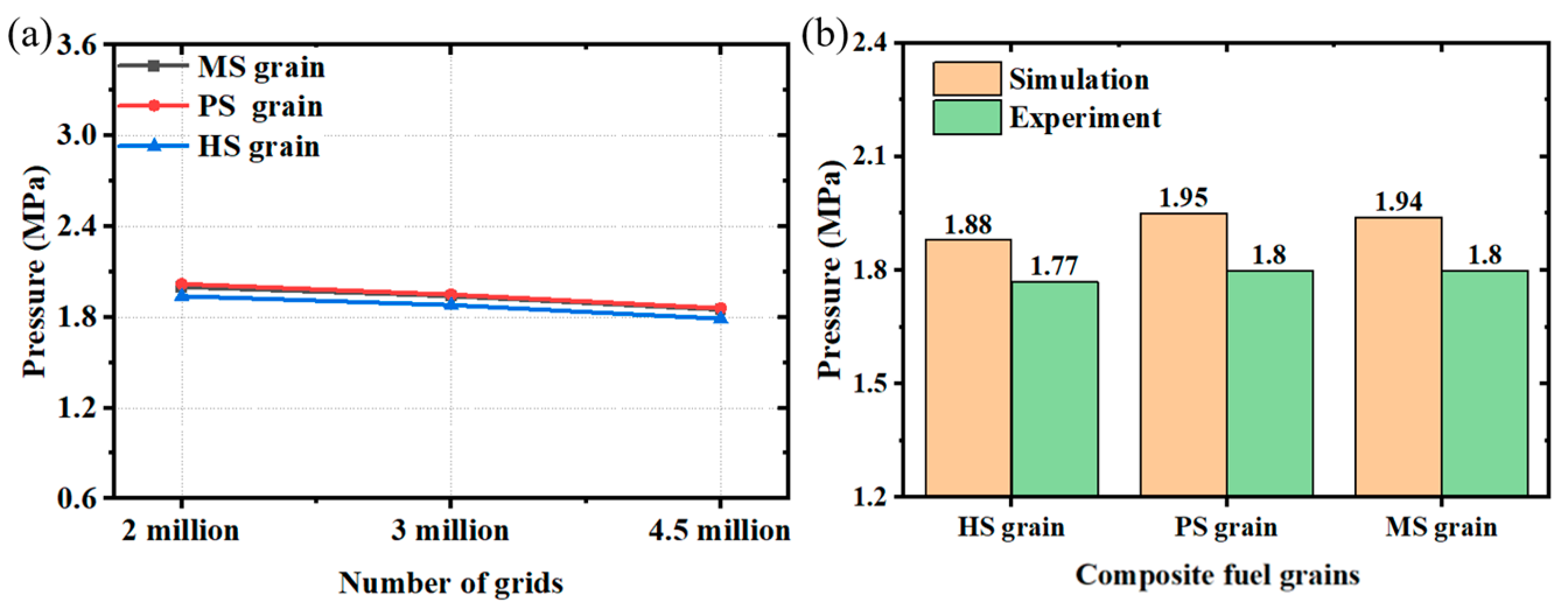
Different grids with a total number of grids of 2 million, 3 million, and 4.5 million were used for the three composite fuel grains during simulation to eliminate the effect of grid size during the numerical simulation. As shown in Figure 11a, the combustion chamber pressures under different grids were very similar for the same grain, with a maximum relative error of 8.6%. Experimental values of the chamber pressure are compared with the numerical simulation results, as presented in Figure 11b. Error estimates of the chamber pressure range from 6.21% to 8.33%. The final model utilized a mesh count of 3 million.

4.2. Flow Characteristics

Figure 12 illustrates the surface streamlines at different locations of the HRE. As shown in Figure 12a, the cross-sectional velocity distribution of the HRE indicates that oxygen flow in the MS grain was faster in the post-chamber region compared with that of the HS and PS grains. Figure 12b shows that the swirl flow field mainly occurred at the near wall of the three composite grains. In particular, at a distance of 25 mm from the front surfaces of the three fuel grains, streamlines in the near wall were significantly disordered. This disorder may be attributed to turbulent flow induced by the reactive force of the blades on the oxygen, with high initial resultant velocity. Additionally, curved streamlines re-emerged at the 75 mm position from the front face of the MS grain. This phenomenon seems to resemble the superposition of two vortex flows moving in opposite directions.
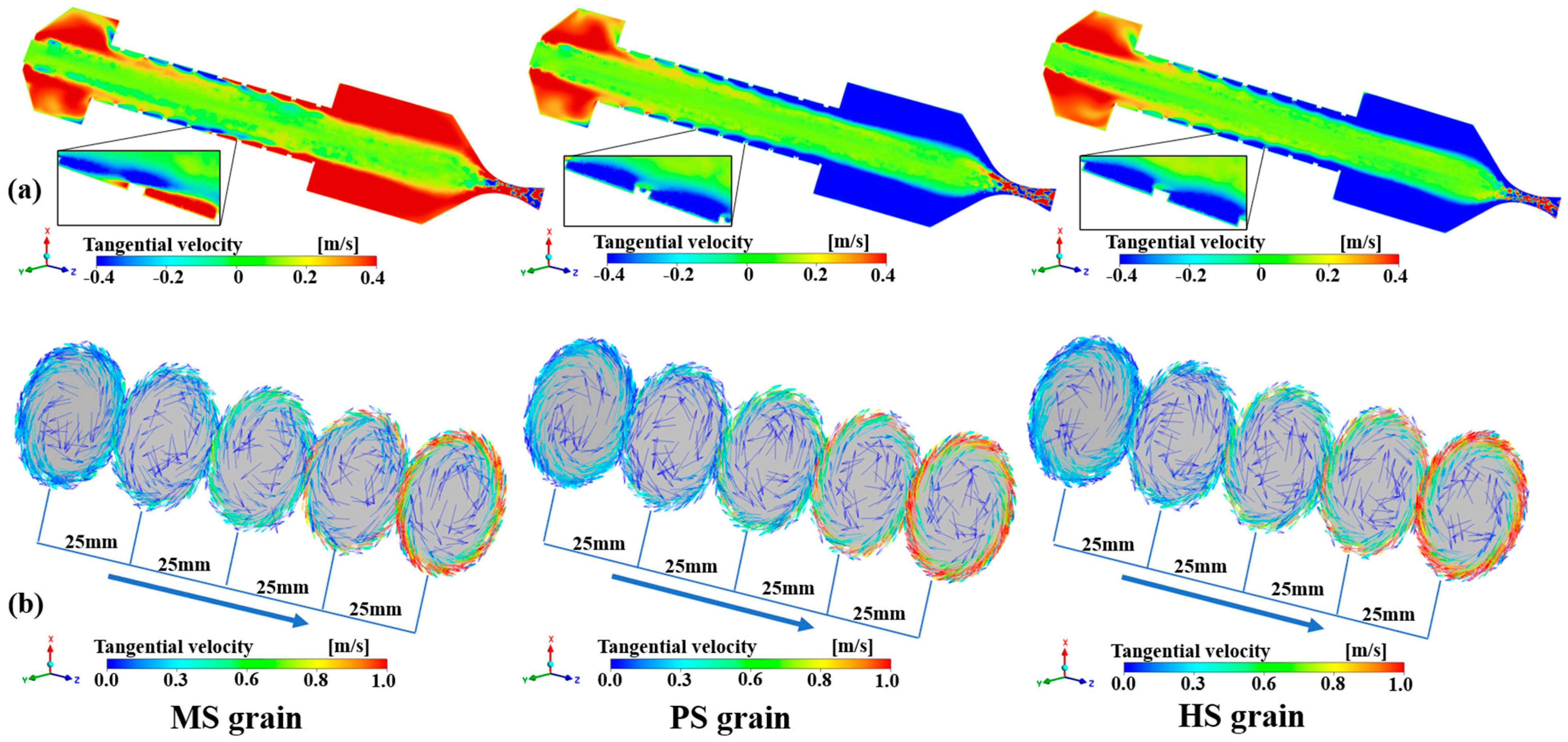
To further investigate surface streamline variations and the swirl flow on the burning effect of the MS grain, the tangential velocity was analyzed. The distribution of the surface tangential velocity vectors is shown in Figure 13a. The red and blue colors indicate areas of strong swirl flow. The color bars of tangential velocities in Figure 13b are scalar, and the arrows on the surface visualize the change in swirl direction.
A reflux area formed on the pre-chamber of the engines, which was opposite to the direction of helical blades due to the high initial flow rate of oxygen. At a distance of 25 mm from the front face on the near wall of the grains, the reflux area of the oxidizer overlapped with the positive swirling flow directed by the blades, two streams of swirling flow with opposite directions. Subsequently, under induction of the blade, the swirl direction of the near walls of the PS and HS grains was mainly guided by the helical blades, and the area of the recirculation zone continuously reduced. Interestingly, this single direction of swirling flow did not persist within the MS grain model. Figure 13 shows that the central area of the MS grain exhibited swirling flows with opposite directions due to the guiding effect of the mirrored module blades and the inertia of oxygen flow. The vector diagram of tangential velocity corroborates the earlier conjecture regarding the curvature of the streamlines. The presence of two opposite vortices significantly fosters the development of turbulence, which in turn facilitates the mixing of the fuel and combustion gases, consequently elevating the combustion efficiency.
An analysis of the swirling distribution on the near-wall surface of the three fuel grains was conducted (refer to black dotted lines in cutaway views of fuel grains in Figure 9). The resulting eddy swirling intensity distribution on the near-wall surface is presented in Figure 14. It is evident that the swirling intensity at the wall of the MS grain was not greatly weakened, which still promoted the shear effect on the inner surface of the grain. The swirling intensity in the blade region of the PS fuel grain was no longer zero, and that of the near wall was higher than for the HS grain. Swirling enhancement is thought to be one reason for the high regression rate of the PS grain.
Figure 15 illustrates the distribution of CO2 and H2O within the HRE and average product mass fractions at the nozzle outlet. Complete combustion of ethylene produces CO2 and H2O; thus, the mass fractions of these products can characterize adequacy of combustion. The average mass fractions of CO2 and H2O in the HRE post-chambers of the MS and PS grains were higher than those of the HS grain, which indicates that the composite fuel grains with a modified modular fuel unit can promote the mixing of the oxidizer and fuel to improve combustion efficiency.
Overall, the present results confirm that composite fuel grains based on a modular fuel unit are capable of improving the combustion characteristics of HRE. The excellent regression rate and combustion efficiency of the MS grain validate the potential of this strategy. Future research in our group will focus on optimization and exploration of this modular fuel design strategy, such as combining structural features of the MS and PS grains. Research on combustion efficiency over time will also be discussed. In addition, a reconstruction technique with time-resolved calculations will be introduced to analyze the data in more detail in the future [43,44]. More complex turbulence modeling and numerical calculations will be taken into account in subsequent studies.

5. Conclusions

A modular fuel strategy for a composite hybrid rocket grain is proposed. The combustion characteristics of the composite fuel grain based on the modular fuel units with modifications were experimentally and numerically studied. The parameters of the engines with different fuel grains were analyzed for average mass flow fluxes of 9.5–28.1 g/s. The mechanism of the performance enhancement of the composite fuel grains with the modified modular units was analyzed using radiation imaging technology and 3D numerical simulation. The specific conclusions are as follows:
(1)
Composite fuel grains with the modified modular units are more conducive to increasing the regression rates. Under an oxygen mass flux of 6.0 g/(s·cm2), the regression rates of the MS and PS grains increased by 8.0% and 14.1%, respectively, compared with that of the HS grain.
(2)
Experimental results show that the composite fuel grains have the advantage of rapidly increasing the radiant intensity and flame thickness. The MS grain had the most significant improvement on combustion performance. The centralized O/F distribution and stable combustion efficiency further illustrated superiority in combustion of the mirrored helical structure.
(3)
Simulation results showed that the pores of the PS grain promoted the development of swirl flow, which increased the regression rate. Two opposite swirling flows resulting from the mirroring configuration significantly fostered the development of turbulence in the MS grain, which improved the mixing of propellant and gas and thus promoted combustion efficiency.

Author Contributions

Conceptualization, X.L. and X.Y.; Methodology, X.L., R.W. and K.W.; Software, Z.W., R.W. and K.W.; Validation, Z.W.; Formal analysis, X.L., K.W. and J.L.; Investigation, Z.W.; Resources, X.L. and X.Y.; Data curation, J.P. and R.W.; Writing—original draft, J.P.; Writing—review & editing, X.L. and Z.W.; Supervision, R.W. and J.L.; Project administration, J.L. and X.Y.; Funding acquisition, X.L. and X.Y. All authors have read and agreed to the published version of the manuscript.

Funding

This study was financed, in part, by the National Natural Science Foundation of China (Grant Nos. 92271117, 12072355, and 11927803), the Key-Area Research and Development Program of Guangdong Province (Grant No. 2021B0909060004), and the Youth Innovation Promotion Association of CAS (Grant No. 2022018).

Data Availability Statement

Data are contained within the article.

Conflicts of Interest

The authors declare no conflict of interest.

Nomenclature

HREhybrid rocket engine
ABSacrylonitrile–butadiene–styrene
MS/PS/HS graincomposite fuel grains with mirrored/perforated/helical blades, respectively
PP grainparaffin-based grain
3Dthree-dimensional
PODproper orthogonal decomposition
O/Foxidizer to fuel ratio
m ˙ o average oxygen mass flow rate
Goxoxidizer mass flux
P ¯ average chamber pressure
r ˙ average regression rate
d0the initial inner diameter of the fuel grain
dfthe inner diameter of the fuel grain after firing experiments
m 0 initial mass of the fuel grain
m f the mass of the fuel grain after firing experiments
η combustion efficiency
C t theoretical characteristic velocity
C e experimentally obtained characteristic velocity
m ¯ g average mass flow rate of the oxidizer
dtthroat diameter of the nozzle
tworking time of the engine
Uorthogonal modes of the flame series
Scorresponding mode energy
Vtime coefficients
Ttranspose of a matrix
λ eigenvalue
Enormalized energy ratio of each mode

References

  1. Mazzetti, A.; Merotto, L.; Pinarello, G. Paraffin-Based Hybrid Rocket Engines Applications: A Review and a Market Perspective. Acta Astronaut. 2016, 126, 286–297. [Google Scholar] [CrossRef]
  2. Martins, P.G.C.; De Souza, K.M.; Boschi, R.F.; Gouvêa, L.H.; Martins, C.A. Performance Comparison of Paraffin/Ethanol Fuel Blends in a Laboratory-Scale Hybrid Rocket Motor. J. Propuls. Power 2023, 39, 696–708. [Google Scholar] [CrossRef]
  3. Gu, X.; Tian, H.; Wang, J.; Liang, T.; Wei, T.; Niu, X.; Cai, G. Operational Instability of a High-Rotational-Speed Electric Pump in a Hybrid Rocket Motor. Aerosp. Sci. Technol. 2023, 140, 108496. [Google Scholar] [CrossRef]
  4. Pal, Y.; Mahottamananda, S.N.; Palateerdham, S.K.; Subha, S.; Ingenito, A. Review on the Regression Rate-Improvement Techniques and Mechanical Performance of Hybrid Rocket Fuels. FirePhysChem 2021, 1, 272–282. [Google Scholar] [CrossRef]
  5. Dhandapani, C.; Blanquart, G.; Karp, A.C.; Jens, E.T.; Rabinovitch, J. Combustion Studies of MMA/GO x for a Hybrid Rocket Motor. Combust. Flame 2023, 256, 112994. [Google Scholar] [CrossRef]
  6. Lee, J.; Woo, K.; Kim, S. Effect of Swirl Intensity Variation on Combustion Characteristics in End-Burning Hybrid Rocket Engines. Acta Astronaut. 2024, 217, 302–311. [Google Scholar] [CrossRef]
  7. Meng, X.; Gao, J.; Tian, H.; Niu, X.; Chen, R.; Cai, G. Study on the Dynamic Numerical Simulation of Flow and Combustion in Hybrid Rocket Motors Based on a Discrete Phase Model. Acta Astronaut. 2024, 215, 156–167. [Google Scholar] [CrossRef]
  8. Zolla, P.; Zavoli, A.; Migliorino, M.T.; Bianchi, D. Integrated Optimization of a Three-Stage Clustered Hybrid Rocket Launcher Using Neural Networks. In AIAA SCITECH 2024 Forum; American Institute of Aeronautics and Astronautics: Reston, VA, USA, 2024. [Google Scholar]
  9. Gallo, G.; Kamps, L.; Hirai, S.; Carmicino, C.; Harunori, N. Prediction of the Fuel Regression-Rate in a HDPE Single Port Hybrid Rocket Fed by Liquid Nitrous Oxide. Combust. Flame 2024, 259, 113160. [Google Scholar] [CrossRef]
  10. Sun, X.; Tian, H.; Li, Y.; Yu, N.; Cai, G. Regression Rate Behaviors of HTPB-Based Propellant Combinations for Hybrid Rocket Motor. Acta Astronaut. 2016, 119, 137–146. [Google Scholar] [CrossRef]
  11. Gallo, G.; Mungiguerra, S.; Savino, R.; Cardillo, D.; Battista, F. Effect of Grain Length on GOx-Paraffin Hybrid Rocket Engines Performance and Regression Rate. Int. J. Heat Mass Transf. 2024, 220, 124978. [Google Scholar] [CrossRef]
  12. Glaser, C.; Hijlkema, J.; Lestrade, J.-Y.; Anthoine, J. Interaction of Multiple Steps in Hybrid Rocket Engines: Experimental Investigation. Acta Astronaut. 2024, 217, 261–272. [Google Scholar] [CrossRef]
  13. Liu, L.; He, X.; Wang, Y.; Chen, Z.; Guo, Q. Regression Rate of Paraffin-Based Fuels in Hybrid Rocket Motor. Aerosp. Sci. Technol. 2020, 107, 106269. [Google Scholar] [CrossRef]
  14. Glaser, C.; Hijlkema, J.; Anthoine, J. Bridging the Technology Gap: Strategies for Hybrid Rocket Engines. Aerospace 2023, 10, 901. [Google Scholar] [CrossRef]
  15. Tianfang, W.; Guobiao, C.; Hui, T.; Hao, Z.; Yuanjun, Z.; Xintong, L. Optimization Design in Single Wagon-Wheel Fuel Grain of Hybrid Rocket Motor. FirePhysChem 2021, 1, 212–221. [Google Scholar] [CrossRef]
  16. Ahn, B.; Kang, H.; Lee, E.; Yun, Y.; Kwon, S. Design of Multiport Grain with Hydrogen Peroxide Hybrid Rocket. J. Propuls. Power 2018, 34, 1189–1197. [Google Scholar] [CrossRef]
  17. Yun, Y.; Huh, J.; Kim, Y.; Heo, S.; Kim, H.; Kwon, S. Scale-Up Validation of Hydrogen Peroxide/High-Density Polyethylene Hybrid Rocket with Multiport Solid Fuel. J. Spacecr. Rocket. 2021, 58, 552–565. [Google Scholar] [CrossRef]
  18. Wei, T.; Cai, G.; Tian, H.; Jiang, X. Experiment and Numerical Research on Regression Rate of Hybrid Rocket Motor with Single-Port Wagon Wheel Fuel Grain. Acta Astronaut. 2023, 207, 265–282. [Google Scholar] [CrossRef]
  19. Yu, X.; Yu, H.; Gao, H.; Zhang, W.; DeLuca, L.T.; Shen, R. 3D Printed Different Polymer Fuel Grains for Hybrid Rocket Engine. FirePhysChem, 2023; in press. Corrected Proof. [Google Scholar] [CrossRef]
  20. Viscor, T.; Kamps, L.; Yonekura, K.; Isochi, H.; Nagata, H. Large-Scale CAMUI Type Hybrid Rocket Motor Scaling, Modeling, and Test Results. Aerospace 2022, 9, 1. [Google Scholar] [CrossRef]
  21. Glaser, C.; Hijlkema, J.; Anthoine, J. Evaluation of Regression Rate Enhancing Concepts and Techniques for Hybrid Rocket Engines. Aerotec. Missili Spaz. 2022, 101, 267–292. [Google Scholar] [CrossRef]
  22. Altman, D.; Holzman, A. Overview and History of Hybrid Rocket Propulsion. In Fundamentals of Hybrid Rocket Combustion and Propulsion; Kuo, K.K., Chiaverini, M.J., Eds.; AIAA: Reston, VA, USA, 2007; Volume 218, pp. 1–36. ISBN 978-1-56347-703-4. [Google Scholar]
  23. Kumar, R.; Ramakrishna, P.A. Effect of Protrusion on the Enhancement of Regression Rate. Aerosp. Sci. Technol. 2014, 39, 169–178. [Google Scholar] [CrossRef]
  24. Kumar, R.; Ramakrishna, P.A. Enhancement of Hybrid Fuel Regression Rate Using a Bluff Body. J. Propuls. Power 2014, 30, 909–916. [Google Scholar] [CrossRef]
  25. Whitmore, S.A. Additively Manufactured Acrylonitrile-Butadiene-Styrene–Nitrous-Oxide Hybrid Rocket Motor with Electrostatic Igniter. J. Propuls. Power 2015, 31, 1217–1220. [Google Scholar] [CrossRef]
  26. Whitmore, S.A.; Walker, S.D.; Merkley, D.P.; Sobbi, M. High Regression Rate Hybrid Rocket Fuel Grains with Helical Port Structures. J. Propuls. Power 2015, 31, 1727–1738. [Google Scholar] [CrossRef]
  27. Whitmore, S.A.; Walker, S.D. Engineering Model for Hybrid Fuel Regression Rate Amplification Using Helical Ports. J. Propuls. Power 2017, 33, 398–407. [Google Scholar] [CrossRef]
  28. Bisin, R.; Paravan, C.; Alberti, S.; Galfetti, L. A New Strategy for the Reinforcement of Paraffin-Based Fuels Based on Cellular Structures: The Armored Grain—Mechanical Characterization. Acta Astronaut. 2020, 176, 494–509. [Google Scholar] [CrossRef]
  29. Bisin, R.; Paravan, C. A New Strategy for the Reinforcement of Paraffin-Based Fuels Based on Cellular Structures: The Armored Grain—Ballistic Characterization. Acta Astronaut. 2023, 206, 284–298. [Google Scholar] [CrossRef]
  30. Wang, Z.; Lin, X.; Li, F.; Yu, X. Combustion Performance of a Novel Hybrid Rocket Fuel Grain with a Nested Helical Structure. Aerosp. Sci. Technol. 2020, 97, 105613. [Google Scholar] [CrossRef]
  31. Lin, X.; Qu, D.; Chen, X.; Wang, Z.; Luo, J.; Meng, D.; Liu, G.; Zhang, K.; Li, F.; Yu, X. Three-Dimensional Printed Metal-Nested Composite Fuel Grains with Superior Mechanical and Combustion Properties. Virtual Phys. Prototyp. 2022, 17, 437–450. [Google Scholar] [CrossRef]
  32. Qu, D.; Lin, X.; Zhang, K.; Li, Z.; Wang, Z.; Liu, G.; Meng, Y.; Luo, G.; Wang, R.; Yu, X. Additively Manufactured Aluminium Nested Composite Hybrid Rocket Fuel Grains with Breathable Blades. Virtual Phys. Prototyp. 2023, 18, e2235680. [Google Scholar] [CrossRef]
  33. Glaser, C.; Gelain, R.; Bertoldi, A.E.M.; Levard, Q.; Hijlkema, J.; Lestrade, J.-Y.; Hendrick, P.; Anthoine, J. Experimental Regression Rate Profiles of Stepped Fuel Grains in Hybrid Rocket Engines. Acta Astronaut. 2023, 204, 186–198. [Google Scholar] [CrossRef]
  34. Mastorakos, E. Ignition of Turbulent Non-Premixed Flames. Prog. Energy Combust. Sci. 2009, 35, 57–97. [Google Scholar] [CrossRef]
  35. Luo, J.; Zhang, Z.; Lin, X.; Wang, Z.; Kun, W.; Zhou, G.; Zhang, S.; Li, F.; Yu, X.; Wu, J. Flame Dynamics in the Combustion Chamber of Hybrid Rocket Using Multiangle Chemiluminescence. J. Propuls. Power 2023, 39, 482–491. [Google Scholar] [CrossRef]
  36. Tan, G.; Tian, H.; Gu, X.; Meng, X.; Wei, T.; Zhang, Y.; Cai, G. Flow Feedback Control Based on Variable Area Cavitating Venturi and Its Application in Hybrid Rocket Motors. Acta Astronaut. 2023, 211, 238–248. [Google Scholar] [CrossRef]
  37. Gordon, S.D.; Mcbride, B.J. Computer Program for Calculation of Complex Chemical Equilibrium Compositions; No. NAS 1.61: 1311; NASA Lewis Research Center: Cleveland, OH, USA, 1994. [Google Scholar]
  38. Zhang, C.; Yan, Y.; Shen, K.; Xue, Z.; You, J.; He, Z. Comparative Analysis of Combustion Stability and Flow Performance in Micro Combustor Based on the Synergistic Action of Slotted Blunt Body and Front-Baffle. Appl. Therm. Eng. 2024, 237, 121802. [Google Scholar] [CrossRef]
  39. Hu, J.; Wang, Y.; Liu, H.; Chen, W.; Xu, Y. Comparative Study on Modal Decomposition Methods of Unsteady Separated Flow in Compressor Cascade. J. Northwestern Polytech. Univ. 2020, 38, 121–129. [Google Scholar] [CrossRef]
  40. Strang, G.; Press, W.-C. Introduction to Linear Algebra, 6th ed.; Wellesley-Cambridge Press: Wellesley, MA, USA, 1993. [Google Scholar]
  41. Taira, K.; Brunton, S.L.; Dawson, S.T.M.; Rowley, C.W.; Colonius, T.; McKeon, B.J.; Schmidt, O.T.; Gordeyev, S.; Theofilis, V.; Ukeiley, L.S. Modal Analysis of Fluid Flows: An Overview. AIAA J. 2017, 55, 4013–4041. [Google Scholar] [CrossRef]
  42. Løvås, T.; Malik, N.; Mauss, F. Global Reaction Mechanism for Ethylene Flames with Preferential Diffusion. Combust. Sci. Technol. 2010, 182, 1945–1960. [Google Scholar] [CrossRef]
  43. Cassese, S.; Mungiguerra, S.; Guida, R.; Cecere, A.; Savino, R. Regression Rate and Performance Analysis via Ballistic Reconstruction of a Small-Scale H2O2-Based Hybrid Rocket Fuelled by Polyvinyl Chloride. Aerosp. Sci. Technol. 2024, 146, 108911. [Google Scholar] [CrossRef]
  44. Nagata, H.; Nakayama, H.; Watanabe, M.; Wakita, M.; Totani, T. Accuracy and Applicable Range of a Reconstruction Technique for Hybrid Rockets. Adv. Aircr. Spacecr. Sci. 2014, 1, 273–289. [Google Scholar] [CrossRef]
Figure 1. Structures of modular fuel unit, HS grain, PS grain, and MS grain.
Aerospace 11 00262 g001
Figure 2. General schematic of laboratory-scale hybrid rocket engine.
Aerospace 11 00262 g002
Figure 3. Pressure and the oxygen mass flow rate as a function of time for the four grains for average oxygen mass flux of: (a) 3.1 g/(s·cm2), (b) 4.0 g/(s·cm2), (c) 5.5 g/(s·cm2), and (d) plot of average pressure as a function of average oxygen mass flux.
Aerospace 11 00262 g003
Figure 4. Variation in regression rates with oxygen mass flux for different fuel grains.
Aerospace 11 00262 g004
Figure 5. (a) Distribution of characteristic velocities and the oxidizer-to-fuel ratio (O/F) for four grains and (b) average O/F as a function of average oxygen mass flux.
Aerospace 11 00262 g005
Figure 6. Radiative intensity and pressure changes with time for the four grains: (a) MS grain, (b) PS grain, (c) HS grain, and (d) PP grain.
Aerospace 11 00262 g006
Figure 7. The inner surface of the fuel grains before and after combustion.
Aerospace 11 00262 g007
Figure 8. Radiant luminescence images as a function of time from ignition for different grains.
Aerospace 11 00262 g008
Figure 9. (a) Proper orthogonal decomposition cumulative energy distribution of modes and (b) first six modes of the images.
Aerospace 11 00262 g009
Figure 10. Simplified three-dimensional computational models for the engine inner flow field of three composite fuel grains.
Aerospace 11 00262 g010
Figure 11. (a) Combustion chamber pressure of composite fuel grains and (b) comparison of chamber pressure for simulation and experimental results.
Aerospace 11 00262 g011
Figure 12. (a) Surface velocity distributions of hybrid rocket engine and (b) streamline diagrams at 25 mm axially equidistant positions for the three composite fuel grains.
Aerospace 11 00262 g012
Figure 13. (a) Tangential velocity distribution of hybrid rocket engine and (b) surface tangential vector distribution of grains at 25 mm axially equidistant positions.
Aerospace 11 00262 g013
Figure 14. Tangential velocity distributions along the Z-axis of three different fuel grains.
Aerospace 11 00262 g014
Figure 15. Mass fractions of: (a) CO2 and (b) H2O, and (c) average product mass fractions at nozzle outlets.
Aerospace 11 00262 g015
Table 1. Test results of fuel grains.
No.Grain m ˙ o (g/s)Gox g/(s·cm2) P ¯ (MPa) r ˙ (mm/s)O/F
1HS grain10.062.341.020.761.95
212.032.731.110.881.95
313.763.111.280.882.22
415.333.441.490.942.29
518.373.981.741.12.22
618.254.011.771.042.45
718.504.011.831.112.29
819.094.161.811.052.44
920.714.471.971.122.51
1022.364.742.081.212.44
1124.115.082.231.262.50
1224.405.282.131.162.81
1326.275.552.391.272.73
1428.095.982.451.233.01
15PS grain9.612.180.950.841.65
1611.602.641.100.861.95
1712.112.701.140.941.81
1813.793.041.330.991.95
1916.753.641.591.072.14
2017.453.781.741.082.20
2118.473.951.821.152.16
2218.594.011.801.142.23
2320.874.441.971.232.26
2422.404.762.111.222.44
2523.734.932.271.342.27
2624.065.062.221.262.50
2724.665.212.401.282.57
2825.705.372.411.352.51
29MS grain9.492.240.920.711.98
3012.122.761.200.862.01
3113.342.961.360.961.93
3214.733.231.491.021.96
3316.963.741.661.042.21
3418.433.951.801.162.13
3521.184.532.031.192.34
3623.514.872.331.362.21
3725.695.422.481.322.43
3827.025.632.621.372.54
39PP grain9.772.320.890.682.15
4011.422.661.000.752.22
4113.903.191.170.792.52
4217.464.031.460.823.08
4318.744.271.560.883.03
4418.924.281.690.912.93
4519.604.381.660.883.13
4619.174.381.650.962.84
4720.584.541.781.002.84
4821.424.811.920.953.21
4924.645.442.001.023.34
5025.875.682.231.033.46
Table 2. Global reaction mechanism for ethylene.
No.Reaction
1O2 + C2H4   2CO + 2H2
2O + CO(+M) CO2 (+M)
3OH + CO H + CO2
4O2 + H2 OH + OH
5O2 + H OH + O
6OH + H2   H + H2O
7O + H2 + M   H2O + M
82H+   H2 + M
9C2H4   C2H2 + H2
10C2H2 + 2OH   2H2 + 2CO
Disclaimer/Publisher’s Note: The statements, opinions and data contained in all publications are solely those of the individual author(s) and contributor(s) and not of MDPI and/or the editor(s). MDPI and/or the editor(s) disclaim responsibility for any injury to people or property resulting from any ideas, methods, instructions or products referred to in the content.