1. Introduction
Boundary element methods (BEM, also referred to as panel methods) arise from applying the method of Green’s functions to a given governing partial differential equation (PDE) and a set of boundary conditions [
1]. BEMs are advantageous because the computational domain consists of only the boundary of the fluid or structural domain of interest. On this boundary, the strengths of certain singularities (sources, doublets, and/or vortices in fluid dynamics) are solved for that uniquely determine the solution to the governing PDE everywhere in the domain. Rather than treating the boundary as one continuous whole, boundary element methods solve a given problem by discretizing the domain boundary into discrete elements or panels. The singularity distributions across each panel are defined by certain parameters, which, when combined with appropriate boundary conditions, may be solved for using a linear system of equations. Solving this system is the focus of this work. For greater detail on other aspects of a BEM, particularly as applied to the problem of supersonic aerodynamics, see [
2,
3,
4,
5,
6,
7,
8,
9]. The paper by Erickson [
2] is a particularly good introduction to panel methods. References [
3,
4] deal with the theory and implementation of the panel code PAN AIR and, while extremely dense, give good information. A more digestible treatment of compressible panel methods is given in [
5]. The papers by Maruyama et al. [
6], Youngren et al. [
7], and Davis [
8] describe other implementations of a compressible panel method.
When the governing PDE for a BEM is elliptic (such as with methods for electrostatics, linearized elastostatics, and subsonic aerodynamics), each panel exerts an influence everywhere in the computational domain. Because of this, the A matrix in the linear system of equations within an elliptic BEM has all non-zero coefficients. This is different from finite-volume or finite-element methods, where the linear system of equations is very sparse.
The efficient solution of the dense system of equations in an elliptic BEM has been investigated previously [
10,
11,
12,
13,
14,
15,
16,
17,
18]. In 1987, Mullen and Rencis evaluated different iterative matrix solvers for a 2D Laplacian BEM [
10]. For the computing power available to them at that time, Mullen and Rencis found that the iterative schemes they considered could not compete with direct Gauss elimination. However, shortly thereafter, in 1992, Mansur et al. showed that iterative methods including the bi-conjugate-gradient method performed faster than Gauss elimination [
11]. That same year, Barra et al. demonstrated the usefulness of GMRES for solving dense BEM systems [
12], and in 1996, Boschitsch et al. showed how the fast-multipole method coupled with a GMRES solver could be used to significantly reduce panel method computation times [
13]. Willis et al. demonstrated the same in 2005 [
14]. The usefulness of Krylov subspace methods, such as GMRES, for dense BEM systems was confirmed in 2007 by Xiao and Chen [
15]. Further investigations into improved convergence for GMRES were presented in 2019 by Yao et al. [
16] and in 2021 by Sun et al. [
17]. Davey and Bounds in 1998 showed how a generalized SOR method could be effectively used for the dense system of equations in an elliptic BEM [
18]. Thus, the efficient solution of the dense, asymmetric system of equations arising from an elliptic BEM has been and continues to be a topic of significant interest.
On the other hand, when the governing PDE is hyperbolic, each panel only exerts an influence within a limited region. The Prandtl–Glauert equation, which is the governing equation for linearized supersonic flow, is hyperbolic, meaning the influence of a given panel is limited to a downstream region known as the domain of influence [
19]. Because of this limited influence, the resulting system matrix contains many elements that are identically zero. However, there may be many downstream control points within the domain of influence, and so the system of equations is still not sparse. To the knowledge of the authors, the efficient solution of such a neither dense nor sparse system of equations has not yet been considered in the available literature. One of the most well-known supersonic panel methods, PAN AIR, simply used LU decomposition to solve this system [
4]. The matrix solvers used by other supersonic panel codes (such as MARCAP [
6] or CPanel [
8]) are not reported.
The purpose of this work is to assess various methods for solving the linear system of equations arising from a supersonic BEM. In particular, the structure of the linear system of equations is examined to facilitate the development of a solver specifically tailored to solving the supersonic problem. The supersonic BEM considered here is fully described in [
5,
20], and the source code is available at [
21,
22]. This BEM is implemented on an unstructured mesh of triangles with linear–doublet–constant–source panels. The traditional Morino formulation is used to determine the unknown source and doublet strengths [
3,
6,
20].
Today, it is common to improve computational efficiency by parallelizing as many operations as possible. However, parallelization adds another dimension to assessing solver performance, and this extra dimension is outside the scope of the current work. Parallelization can only improve the run time of a given algorithm by a factor of how many parallel threads are used. The total CPU time (number of threads multiplied by the time on each thread) is unchanged or even increased (due to communication overhead) by parallelization. Thus, parallelization has no effect on the order of complexity of the method. As the number of unknowns increases, a solution method with a low order of complexity will run faster than a solution method with a high order of complexity, even if the latter method can be efficiently parallelized. For these reasons, all methods described here are implemented in serial, and only serial performance is compared. It is common practice in the technical literature to consider only serial implementation at first for a newly developed method (e.g., see [
15,
23,
24]). Some discussion on the parallelization of each method will be given, but such is not the focus of this work.
This paper proceeds as follows. First, the structure of the linear system matrix is examined, and a method is presented for arranging the system to obtain better solver performance. Various methods for solving the linear system are then presented, including a novel method based on Givens rotations. The relative performance of each method is then assessed and discussed.
2. Linear System of Equations from the Supersonic BEM
While the focus of this work is on matrix solvers, a brief overview of supersonic panel methods is necessary in order to understand the structure of the system of equations being solved. The structure of the resultant linear system of equations will then be discussed. An algorithm for ensuring a favorable matrix structure will then be presented.
2.1. Supersonic Panel Methods
The supersonic panel method considered here finds solutions to the supersonic (
) Prandtl–Glauert equation [
19,
20,
25]
where
is the freestream Mach number,
is the perturbation velocity potential, and subscripts denote (double) derivatives with respect to the subscripted variables. The Prandtl–Glauert equation is the simplest equation governing three-dimensional flow that takes compressibility into account.
The Prandtl–Glauert equation is also linear, and so may be solved using the method of Green’s functions [
26]. Applying Green’s third identity to Equation (
1) results in the boundary integral equation for a point
in the flow [
25,
27]
where the supersonic Green’s function,
G, is given by
and
and
represent surface distributions of supersonic sources and doublets, respectively,
S is the surface of the configuration being analyzed,
is the point of integration on
S, and
is the conormal vector to
S [
19]. Equation (
2) states that, for any flow satisfying Equation (
1), the velocity potential,
, may be found as a function of the source and doublet strengths on the boundary of the flow,
S. This ability to simulate a full three-dimensional flow field using only unknowns on the boundary is what makes panel methods very fast compared to other methods such as finite-volume CFD.
However, for most flows, the correct source and doublet strengths are not known a priori. These may be determined by first discretizing Equation (
2) and then applying appropriate boundary conditions. The surface,
S, is divided into panels, each with a distribution of
and
governed by a finite set of unknown parameters. Then, for this work, the Morino boundary condition formulation is applied. Within the Morino formulation [
3,
20], the boundary conditions are
where
is the direction of the freestream,
is the local surface normal, and
is the perturbation potential inside the body being analyzed. Using Equation (
4), the source strengths are first calculated based on the freestream and local panel geometry. Control points are then placed inside
S, at which the total perturbation potential calculated using Equation (
2) needs to satisfy Equation (
5). For this work, the control points are placed just inside the surface from each vertex. The doublet strengths are also defined at each mesh vertex, resulting in a square system of equations. Writing Equation (
2) for each control point in terms of the unknown doublet strengths results in a linear system of equations of the form
where
A is a square, asymmetric, indefinite matrix called the
aerodynamic influence coefficient (AIC) matrix,
x is a vector of doublet strengths, and
b contains the negative of the potential induced by the surface sources at each control point [
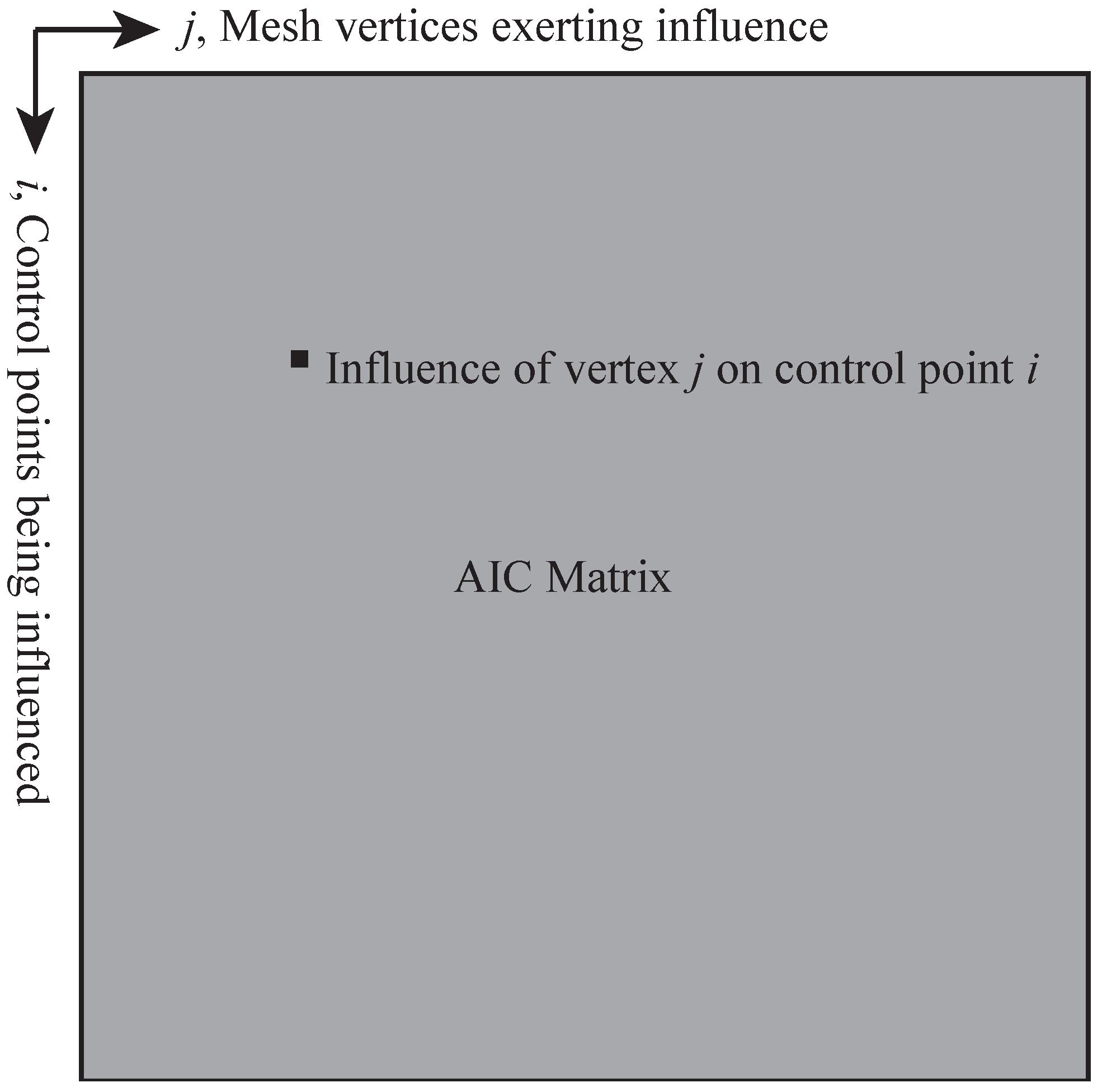
25]. The structure of the AIC matrix is such that the rows correspond to which control point is being influenced, and the columns correspond to which vertex is exerting an influence. This is shown diagrammatically in
Figure 1. Solving this matrix equation will then give the correct surface doublet strengths, from which the entire flow field is specified. This may be performed using any convenient matrix solver; however, it will be shown here that the supersonic AIC matrix has a particular structure that can be exploited to quickly solve the system.
2.2. Structure of the Supersonic Matrix Equation
As may be seen from Equation (
3), in supersonic flow, disturbances only propagate downstream (i.e., downstream panels do not influence upstream control points) [
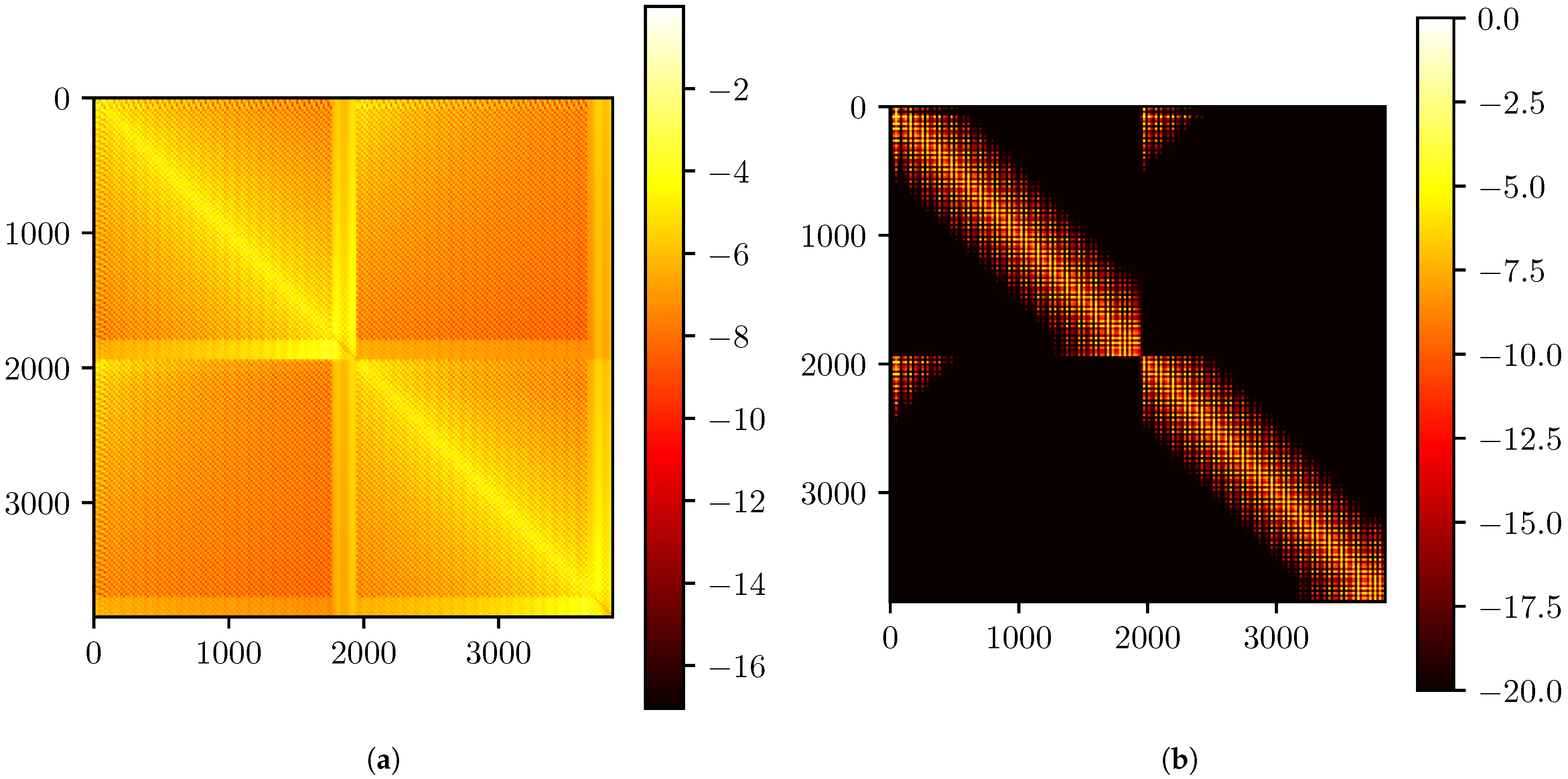
19]. Because of this, many elements in the AIC matrix will be zero. This is unlike a panel method for subsonic flow, where disturbances propagate throughout the entire flow field and the resulting AIC matrix is entirely filled-in. To illustrate this difference, the AIC matrices for an isolated wing in subsonic and supersonic flow are shown in
Figure 2. While these two matrices share qualitative similarities, such as the clustering of high-magnitude coefficients near the diagonal, the difference between the two flow regimes is clear.
The ordering of the AIC matrices represented in
Figure 2 came from the order of the vertices in the mesh file. Again, the unknown doublet strengths are defined at each vertex, and each control point is associated with a vertex. Because of this, there is no useful pattern to the non-zero elements in the supersonic AIC matrix (
Figure 2b).
However, since it is known that the panels in the supersonic case exert no upstream influence, if the mesh vertices were arranged in order relative to the freestream direction, then most of the non-zero elements in the AIC matrix would appear in a single region of the matrix. This is evident in
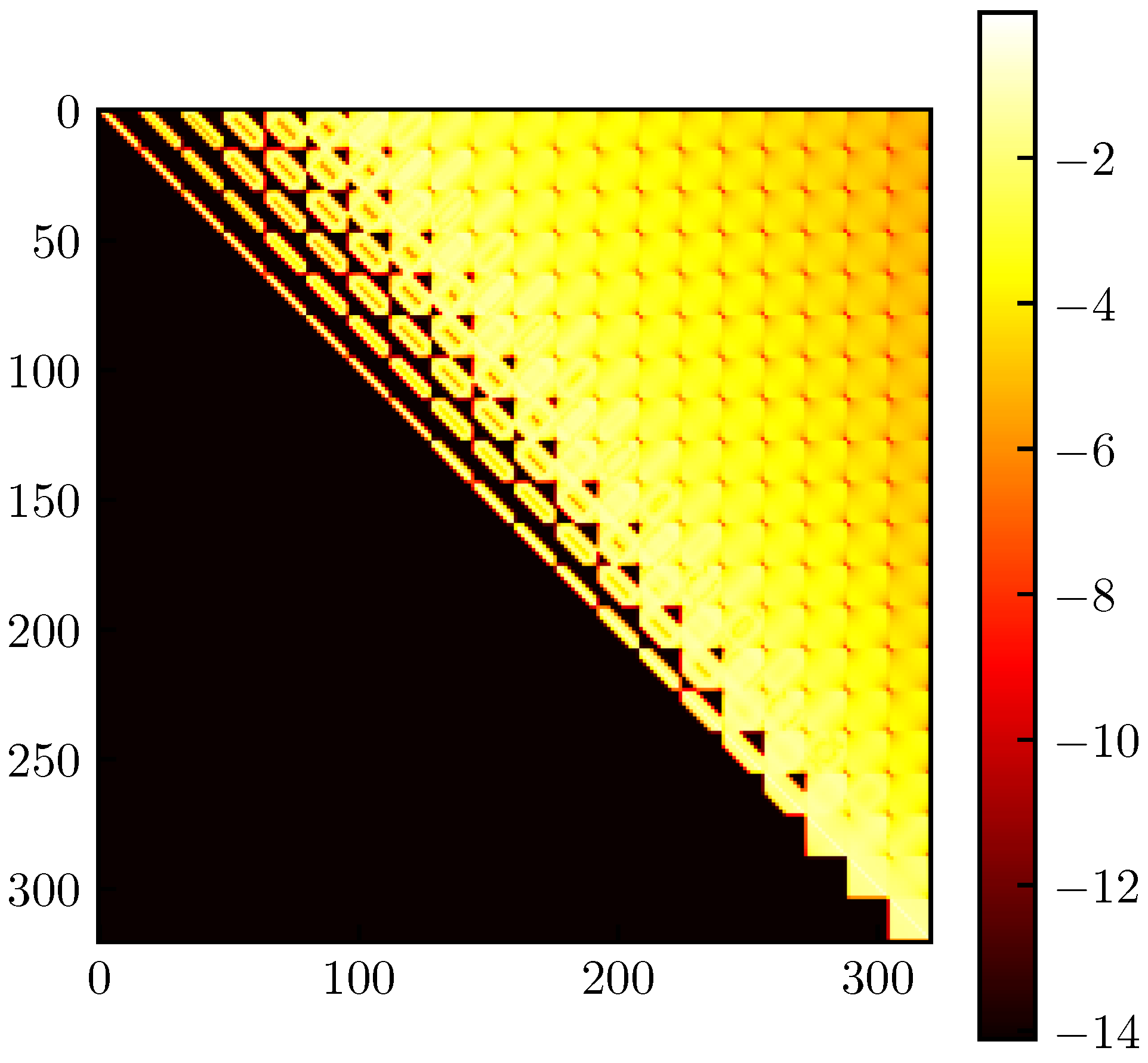
Figure 3, which shows the AIC matrix for a 10° cone in supersonic flow. The mesh file for this particular cone was generated such that the vertices were listed starting at the base (downstream) and ending at the tip of the cone (upstream). Recalling how the AIC matrix is formed (
Figure 1), the first row of the AIC matrix (corresponding to the most-downstream control point) is mostly filled-in, since it is influenced by most of the vertices in the mesh. Moving down the rows of the AIC matrix (corresponding to moving upstream through control points), more and more elements on the left end of the row become zero. The zero elements are clustered at the left end of the row because those elements represent vertices that are further downstream (i.e., those vertices that influence fewer control points).
The AIC matrix shown in
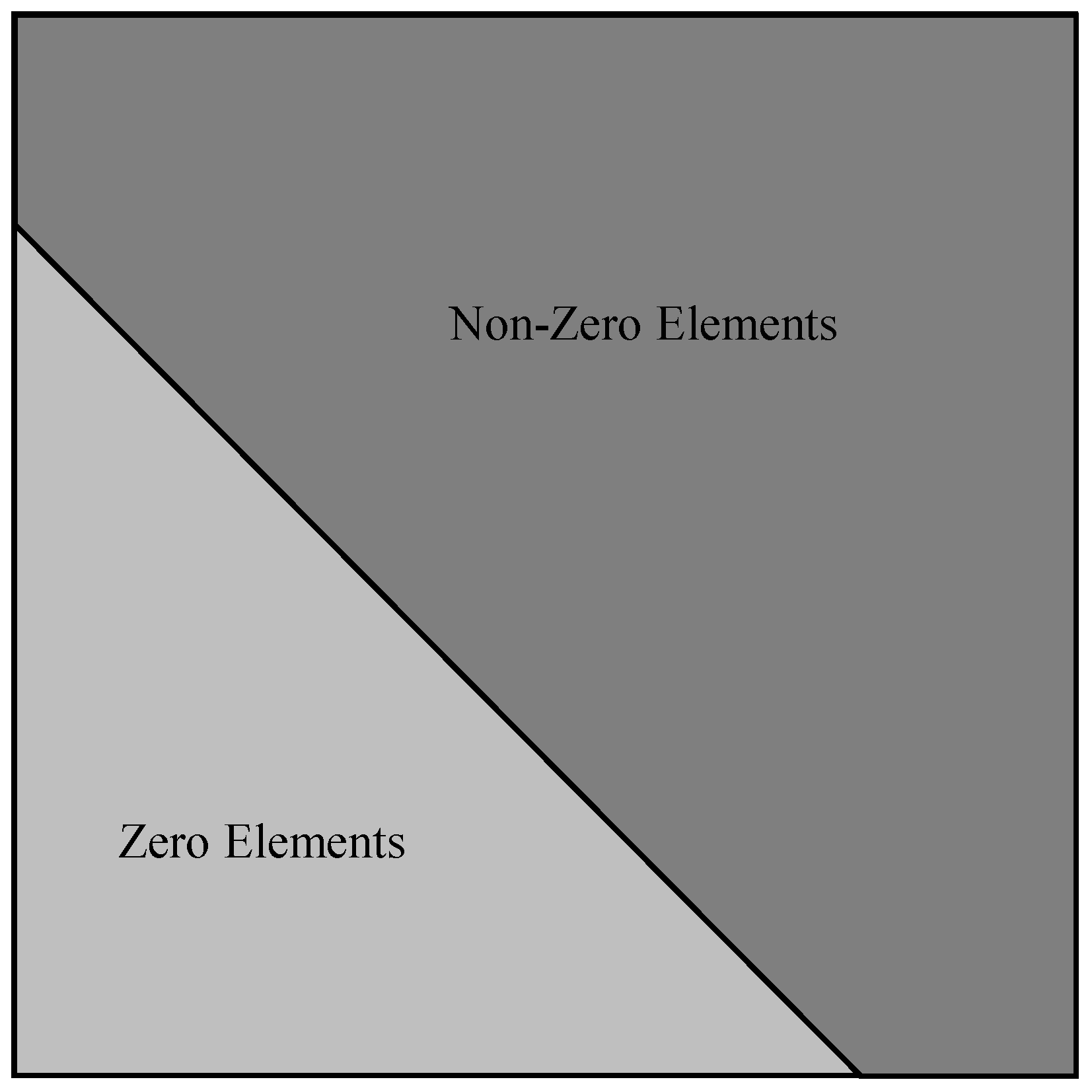
Figure 3 is almost upper-triangular. However, not all elements left of the diagonal are zero. This arises because a vertex may still have an influence on a control point upstream of itself if that vertex belongs to a panel which does influence that control point, because the doublet strength at that vertex helps determine the doublet distribution over the entire panel. However, despite not being upper-triangular, the AIC matrix has a definite structure where the non-zero elements are clustered towards the upper-right. One can imagine drawing a pentagon around these non-zero elements, such as shown in
Figure 4. Because of this shape, such a matrix will be called
upper-pentagonal. Just as an upper-triangular matrix has non-zero elements bounded by a triangle, an upper-pentagonal matrix has non-zero elements bounded by a pentagon.
In mathematical terms, an upper-pentagonal matrix is here defined as follows.
Definition 1. A given matrix, A, having elements is upper-pentagonal, ifwhere the quantity is called the lower bandwidth. This lower bandwidth denotes the lowest subdiagonal that contains non-zero elements. As defined here, an upper-triangular matrix is a special case of an upper-pentagonal matrix having , and an upper-Hessenberg matrix is one with . A matrix simply being upper pentagonal is nothing special. Considering Definition 1, even a matrix with all non-zero elements may be considered upper-pentagonal with bandwidth , where N is the size of the matrix, assuming the matrix is square. As will be shown later, to efficiently solve the linear system of equations, it is best to have . Thus, the goal is to obtain an upper-pentagonal matrix with small lower bandwidth.
2.3. Sorting Algorithm for Obtaining Upper-Pentagonal Form
An algorithm has been developed for rearranging the mesh vertices such that the AIC matrix is upper-pentagonal with small lower bandwidth. This algorithm may be applied to any geometry and is only a function of the vertex locations and freestream direction. The first step of this algorithm is to sort all vertices based on the negative of their downstream distance. If
is the location of the
i-th vertex, then the negative of the downstream distance,
, is given by
where
is the freestream velocity vector.
The second step of the algorithm is to sort all vertices based on the negative of the downstream distance (same as Equation (
8)) of their most-downstream neighboring vertex. This is because each neighbor of a given vertex will help determine the influence of that vertex through setting the distribution parameters over shared panels, even if the neighbor vertex itself falls outside of the domain of dependence. Since many vertices share downstream neighbors, this second sort is non-unique. Hence, a stable sorting algorithm (such as insertion sort) is required for the second sort so that the ordering from the first sorting pass is preserved whenever the second pass encounters a tie.
This method is described in Algorithm 1. For efficiency, instead of rearranging the mesh vertices in memory, the sorting algorithm is implemented to produce a permutation vector that gives the ordering of the rearranged vertices.
| Algorithm 1 Method for sorting mesh vertices such that the AIC matrix will be upper-pentagonal |
- 1:
Input - 2:
N Number of mesh vertices - 3:
Vertex locations - 4:
Freestream velocity - 5:
Output - 6:
P Vector of vertex indices which will sort the AIC matrix (permutation vector) - 7:
- 8:
while do ▹ Get the downstream distances of each vertex and store in x - 9:
- 10:
- 11:
end while - 12:
Indices which will sort x - 13:
- 14:
while do ▹ Get the downstream distances of the most-downstream neighbors - 15:
- 16:
Index of most-downstream neighbor of vertex j - 17:
- 18:
- 19:
end while - 20:
Indices which will sort x using a stable sort - 21:
- 22:
while do ▹ Combine the two permutations - 23:
- 24:
- 25:
- 26:
- 27:
end while
|
The effect of this sorting algorithm is evident in
Figure 5.
Figure 5 represents the AIC matrix for the same mesh as
Figure 2b, but with Algorithm 1 applied. After sorting is applied, the system matrix is upper-pentagonal and has a small bandwidth. Once a matrix is in upper-pentagonal form, its lower bandwidth may be calculated using Algorithm 2.
| Algorithm 2 Method for determining the lower bandwidth of a given matrix A |
- 1:
Input - 2:
A System matrix - 3:
Output - 4:
Lower bandwidth - 5:
- 6:
- 7:
while do ▹ Loop through rows of the matrix starting at the bottom - 8:
found_nonzero ← False - 9:
- 10:
while and not found_nonzero do▹ Loop through columns from the left to the diagonal - 11:
if then ▹ Check for a nonzero element at the current location - 12:
found_nonzero ← True - 13:
else - 14:
- 15:
end if - 16:
end while - 17:
if found_nonzero then - 18:
▹ Keep the largest lower bandwidth - 19:
end if - 20:
- 21:
end while
|
3. Solution Methods
Having developed the upper-pentagonal matrix structure, how to most-efficiently solve such a system of equations will now be investigated. First, a novel algorithm is developed that exploits the upper pentagonal structure just discussed. Then, several other existing matrix solvers are described that may prove useful for solving the supersonic BEM system of equations. For this work, both direct and iterative solvers were considered.
3.1. Novel Method Using QR Decomposition
A well-known direct method for solving linear systems of equations is the QR decomposition, which factors a matrix
A into the form
where
Q is an orthogonal matrix (i.e.,
) and
R is upper triangular [
28]. Once
A has been decomposed, the equation
may be solved quickly, as it may be written as
Since R is upper-triangular, this system may be solved using back-substitution in time. In practice, the product is usually calculated instead of calculating Q by itself.
The QR factorization can be obtained using Givens rotations [
28,
29]. In this method, successive rotations are applied to
A that zero out each of the elements of
A below the diagonal, beginning at the bottom left and proceeding up each column successively. Thus,
A is gradually replaced with
R. At the same time, these rotations are applied to
b, building up
in place of
b.
A single Givens rotation for zeroing out an element of
A is given in Algorithm 3. For efficiently operating on an upper-pentagonal
A matrix, each nonzero subdiagonal element is zeroed out with the diagonal element in the same column. This saves significant time over performing rotations between adjacent matrix elements, as performing rotations only between adjacent matrix elements may result in a large number of trivial swaps with elements that are already zero. As each element is zeroed out, the rotation is also applied to the rest of those two rows and the corresponding elements of
b using Algorithm 4.
| Algorithm 3 Method for generating a standard Givens rotation to zero out element using element x |
- 1:
Input - 2:
Matrix element used to zero out - 3:
Matrix element to be zeroed out - 4:
Output - 5:
c Rotation cosine - 6:
s Rotation sine - 7:
- 8:
- 9:
- 10:
- 11:
|
| Algorithm 4 Method for applying a Givens rotation to a pair of row vectors |
- 1:
Input - 2:
x Upper row vector - 3:
y Lower row vector - 4:
c Rotation cosine - 5:
s Rotation sine - 6:
- 7:
- 8:
|
Using Givens rotations to reduce a dense matrix to upper-triangular form takes
time, since there are
elements below the diagonal to be eliminated and applying each rotation takes
time. However,
R may be obtained faster if it is known which elements are already zero. For example, Givens rotations are often used to reduce a Hessenberg matrix (which has zero elements everywhere below the first subdiagonal) to an upper-triangular matrix [
28,
30,
31]. Since there are only
nonzero elements below the diagonal of a Hessenberg matrix, the reduction to upper-triangular form using Givens rotations takes only
time. For an upper-pentagonal matrix with lower bandwidth
, reduction to upper-triangular form will take only
time. Extrapolating this, any given upper-pentagonal matrix with lower bandwidth
may be reduced to upper-triangular form in
time. If
, then such a method should be much faster than
solvers such as LU decomposition.
A method for solving an upper-pentagonal system (such as would arise from a supersonic panel method using Algorithm 1) using Givens rotations is described in Algorithm 5. This method is called the QR upper-pentagonal (QRUP) solver.
| Algorithm 5 QRUP solver |
- 1:
Input - 2:
N System dimension (system is assumed square) - 3:
A System matrix - 4:
b RHS vector - 5:
Output - 6:
x Solution vector. - 7:
output from lower bandwidth calculation - 8:
- 9:
while do ▹ Loop through columns - 10:
- 11:
while do ▹ Loop up through the rows - 12:
if then ▹ We make sure to save unnecessary computations - 13:
Generate Givens rotation to zero out using - 14:
Apply Givens rotation to the rest of rows j and i of A using c and s - 15:
Apply Givens rotation to rows j and i of b using c and s - 16:
end if - 17:
- 18:
end while - 19:
- 20:
end while - 21:
solution of from back substitution
|
One disadvantage to standard Givens rotations is that each rotation requires computing a square root, which can be computationally expensive [
28]. However, fast Givens rotations exist that do not compute square roots [
30,
32,
33,
34]. These fast rotations avoid square roots by factoring the matrix
A into the form
where
D is a diagonal matrix. The squares of the denominators in the standard Givens rotations are stored in
D. The fast Givens rotations as originally formulated in [
30] are impractical, as
D and
Y must be monitored and periodically normalized to prevent overflow, negating the intended speed benefit [
32]. However, Anda and Park presented an alternative formulation [
33,
34] that dynamically scales
D to prevent overflow. The specific form of the rotation is dependent upon the relative magnitudes of the elements being rotated (
and
) and the diagonal elements in the corresponding rows (
and
). The formulas for these fast rotations are given in
Table 1. For all four rotation types, the final step of applying the rotation is setting
to zero.
In order to use Anda and Park’s [
34] algorithm for the solution of a standard system of equations, the matrix equation must be written as
In the fast Givens algorithm, D is initialized to the identity matrix, which means, initially, and . Since D contains only a non-zero diagonal, it is most-efficiently stored as a vector.
At each step of the algorithm, a fast Givens rotation is generated that zeros out an element of
Y and updates two elements of
D. This rotation is then applied to the other columns of
Y and the corresponding rows of
c (see Algorithm 6). Once the triangularization is complete,
D may be factored out of both sides of Equation (
12), resulting in
which may be solved in
time using back-substitution, since
Y is upper-triangular.
A method for solving an upper-pentagonal system using fast Givens rotations is described in Algorithm 7. This is called the fast QRUP (FQRUP) solver. Similar to the QRUP solver, the FQRUP solver reduces an upper-pentagonal matrix to upper-triangular form in time, but without calculating square roots.
It may be noted here that the QRUP and FQRUP solvers possess another desirable trait beyond reduced order of complexity. Since these solvers are based on QR decomposition, they are rank-revealing [
28]. This means that if the AIC matrix is rank-deficient, then the bottom-right element of the
R matrix will be zero (to numerical precision). This zero element can be checked for and explicitly handled based on the desired behavior. Such explicit handling of a rank-deficient matrix system would be useful for a purely Neumann-based panel method using doublets, for which the AIC matrix is rank-deficient. This would require minimal modification to the algorithms described above.
| Algorithm 6 Method for applying a fast Givens rotation |
- 1:
Input - 2:
x Upper row vector - 3:
y Lower row vector - 4:
Rotation factor - 5:
Rotation factor - 6:
Rotation type - 7:
if
then - 8:
- 9:
- 10:
end if - 11:
if
then - 12:
- 13:
- 14:
end if - 15:
if
then - 16:
- 17:
- 18:
- 19:
end if - 20:
if
then - 21:
- 22:
- 23:
- 24:
end if
|
| Algorithm 7 FQRUP solver |
- 1:
Input - 2:
N System dimension (system is assumed square) - 3:
A System matrix - 4:
b RHS vector - 5:
Output - 6:
x Solution vector - 7:
output from lower bandwidth calculation - 8:
- 9:
▹D is a length-N vector of diagonal elements - 10:
while do ▹ Loop through columns - 11:
- 12:
while do ▹ Loop up through the rows - 13:
if then ▹ We make sure to save unnecessary computations - 14:
Generate fast Givens rotation to zero out using - 15:
Apply fast Givens rotation of type to the rest of rows j and i of A using and - 16:
Apply fast Givens rotation of type to rows j and i of b using and - 17:
end if - 18:
- 19:
end while - 20:
- 21:
end while - 22:
Solution of from back substitution
|
3.2. Existing Methods for Comparison
To assess the performance of the QRUP and FQRUP solvers just developed, they will be compared against four existing matrix solvers, briefly described below.
3.2.1. LU Decomposition
One of the most basic matrix solvers is LU decomposition with partial pivoting. The complexity of this method is
, making it computationally expensive for large meshes. However, it is theoretically exact for well-conditioned systems and robust. It is also the solver that has typically been used for supersonic panel methods (e.g., see [
4,
35]). The implementation of LU decomposition used here was taken from [
36].
3.2.2. BSSOR and BJAC Solvers
Two basic iterative solvers considered here are the block symmetric successive overrelaxation (BSSOR) [
37] and block Jacobi (BJAC) methods [
38]. These methods are attractive mainly for their simplicity. They have also been shown previously to work well for the dense, asymmetric systems arising from elliptic BEMs (e.g., see [
10,
11,
18]).
In this study, the AIC matrix is asymmetric and indefinite, for which point successive overrelaxation and Jacobi iterations are not guaranteed to converge. To alleviate this, both are relaxed, and the block-iterative versions are used rather than the traditional, point-iterative versions. To save time, the blocks along the diagonal are decomposed (using LU decomposition) before the iterations begin.
3.2.3. GMRES
An alternative iterative method is the generalized minimum residual (GMRES) algorithm [
31]. This method has become widely used for modern panel methods (and boundary element methods in general) due to its speed and ability to handle non-symmetric and non-definite matrices (e.g., see [
12,
13,
14,
15,
16,
17,
39]). GMRES is a Krylov subspace method (a family of methods based on the Cayley–Hamilton theorem [
28,
40]), meaning it iteratively builds an approximation to the solution
in the space
where
for some initial guess
. Each iteration of the GMRES algorithm involves adding another dimension to
, updating the orthogonal basis for
(called the Arnoldi update), and then determining the optimal solution in the expanded basis. One of the disadvantages of GMRES is that its memory and computation requirements steadily grow with each iteration [
12]. However, it is guaranteed to converge in
N iterations for an
system, though convergence is typically must faster, making GMRES close to
[
15]. The GMRES algorithm used here comes from [
31].
3.3. Comparison Cases
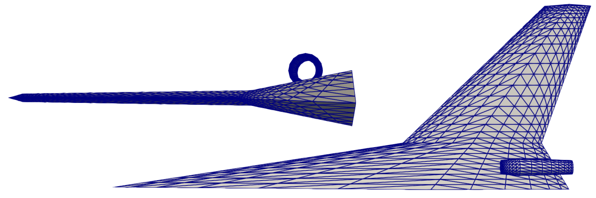
The relative performance of each of the above solvers was assessed by using them to solve the system of equations arising from the supersonic BEM described previously. Three configurations were considered: a circular cone with a 10° half angle, a straight, double-wedge wing with a 5° half angle, and a wing–body configuration with engine nacelles. These configurations are shown in
Figure 6 and
Figure 7. These different configurations allow for exploring the effect of variations in the matrix structure on solver performance. For each case, three different mesh densities were analyzed to estimate the computational complexity of each solver. The resultant system dimension for each mesh refinement level, along with the freestream Mach number, is given in
Table 2 for each configuration.
Each solver was tested with and without sorting the system first using Algorithm 1. While required for the QRUP and FQRUP solvers, initial tests revealed that the sorting algorithm developed here also improved the performance of some iterative methods. Each solver was also tested with and without diagonal preconditioning, as described in [
12].
For both the BJAC and BSSOR solvers, a relaxation factor of 0.8 was used. The block size for these was , meaning the block size changed with each configuration and mesh refinement. Initial tests showed that this block size provided a good balance between the time it took to calculate the block decompositions and the time it took to run the iterations. All iterative solvers had a termination tolerance of and a maximum of 1000 iterations were allowed.
For each solver, the total time required to sort the linear system (or not), apply the diagonal preconditioner (or not), and solve the system was recorded and then averaged over five repeated tests. The norm of the final residual vector was recorded (again averaged) to assess the accuracy of each solver. All tests were run on an OnLogic (South Burlington, VT, USA) K801 workstation with an Intel i9 24-core processor and 64 GB of RAM.
4. Results
In this section, the results from the six solvers for each of the three test cases are presented. The computational orders of complexity of the solvers are then discussed.
4.1. Cone
The first test case was a circular cone with a 10° half angle. The slender shape of the cone makes it such that the upper-pentagonal AIC matrix is very filled-in (see
Figure 3) and has a small lower bandwidth. This is because the domain of influence for any given panel will encompass much of the rest of the cone downstream of it, particularly for panels closer to the tip.
Figure 8 shows the matrix solver run times for the 10° half-angle cone. In this case, the QRUP and FQRUP solvers ran the fastest out of all solvers, with GMRES having comparable run times for the fine mesh. Sorting the system significantly affected the run times only for the QRUP and FQRUP solvers, for which the run times were significantly reduced by sorting, as would be expected. Diagonal preconditioning had no noticeable effect on the run time of any solver.
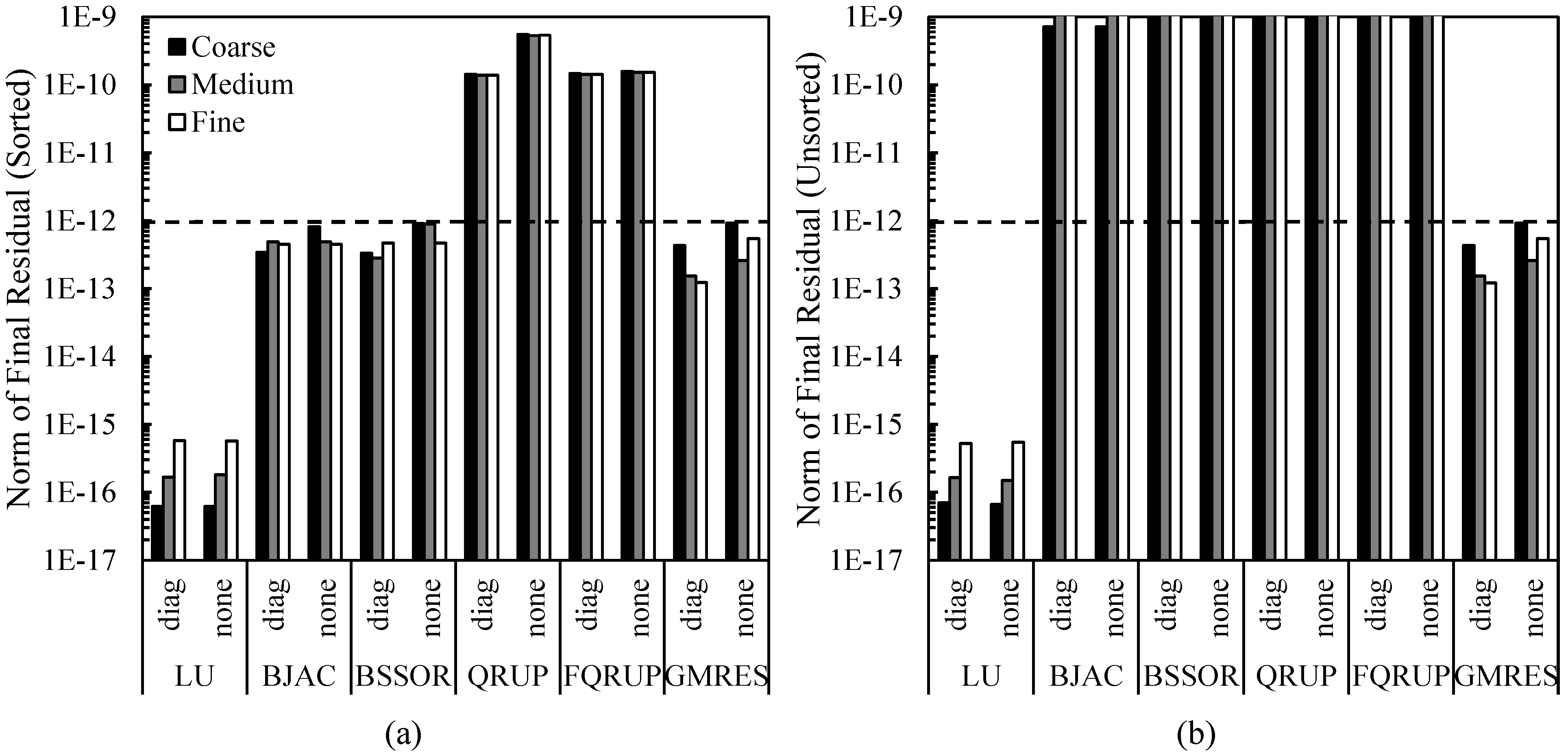
Figure 9 shows the solution residual norms for the different matrix solvers. With the sorting algorithm applied and using diagonal preconditioning, all solvers produced a residual norm of less than
. Without sorting, the QRUP and FQRUP solvers produced unacceptably high residuals. This may be because the many operations required to reduce a non-upper-pentagonal matrix to upper-triangular form resulted in a non-negligible buildup of numerical error, something not seen when relatively few operations were used on the upper-pentagonal system. Preconditioning improved the final accuracy of QRUP, but not FQRUP. This may be due to how the FQRUP solver stores the matrix diagonal separately.
It is useful to observe how the residual error decreases with each iteration of the iterative solvers. This is shown in
Figure 10 for the cases where diagonal preconditioning was applied and the system was sorted. Convergence was very smooth for all solvers, indicating a well-conditioned system.
4.2. Double-Wedge Wing
The second test case was a straight, double-wedge wing with a 5° wedge half angle. The relatively high aspect ratio of the double-wedge wing makes the upper-pentagonal AIC matrix rather sparse (see
Figure 5). This is because any given panel will have relatively few panels within its domain of influence, even if that panel is near the leading edge.
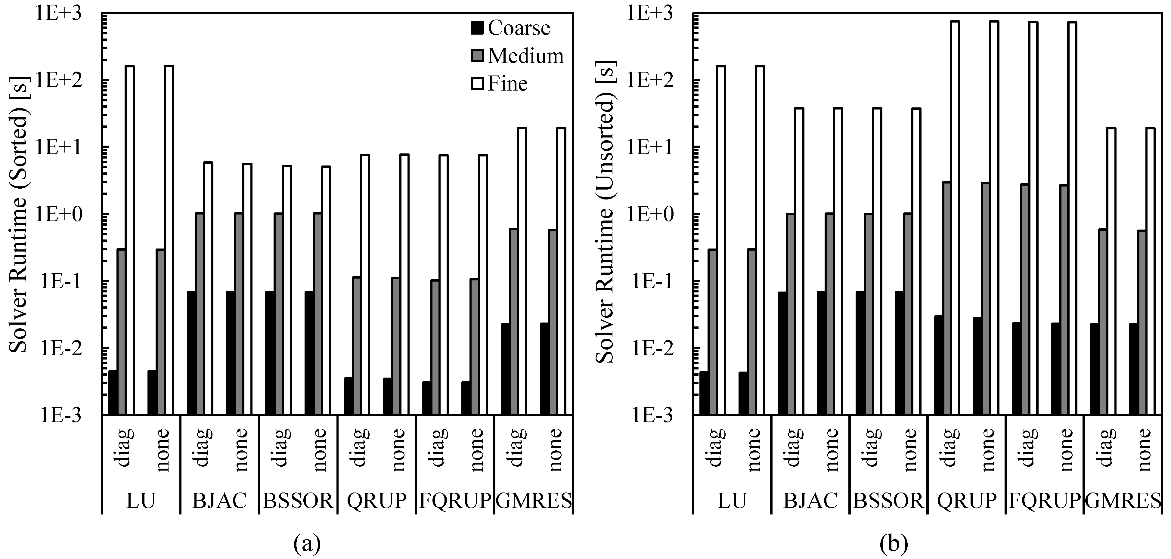
Figure 11 shows the solver run times for the double-wedge wing. For this case, the GMRES solver was the fastest of all the solvers considered. The QRUP and FQRUP solvers still outperformed the LU, BJAC, and BSSOR solvers. As before, sorting the system of equations significantly improved the speed of the QRUP and FQRUP solvers. In addition, sorting the system also significantly improved the run times for the BJAC and BSSOR solvers. It is evident in
Figure 2b that there are large blocks of nonzero elements far from the diagonal of the unsorted AIC matrix. Thus, sorting the system likely improved diagonal dominance, which helps convergence of these methods [
38].
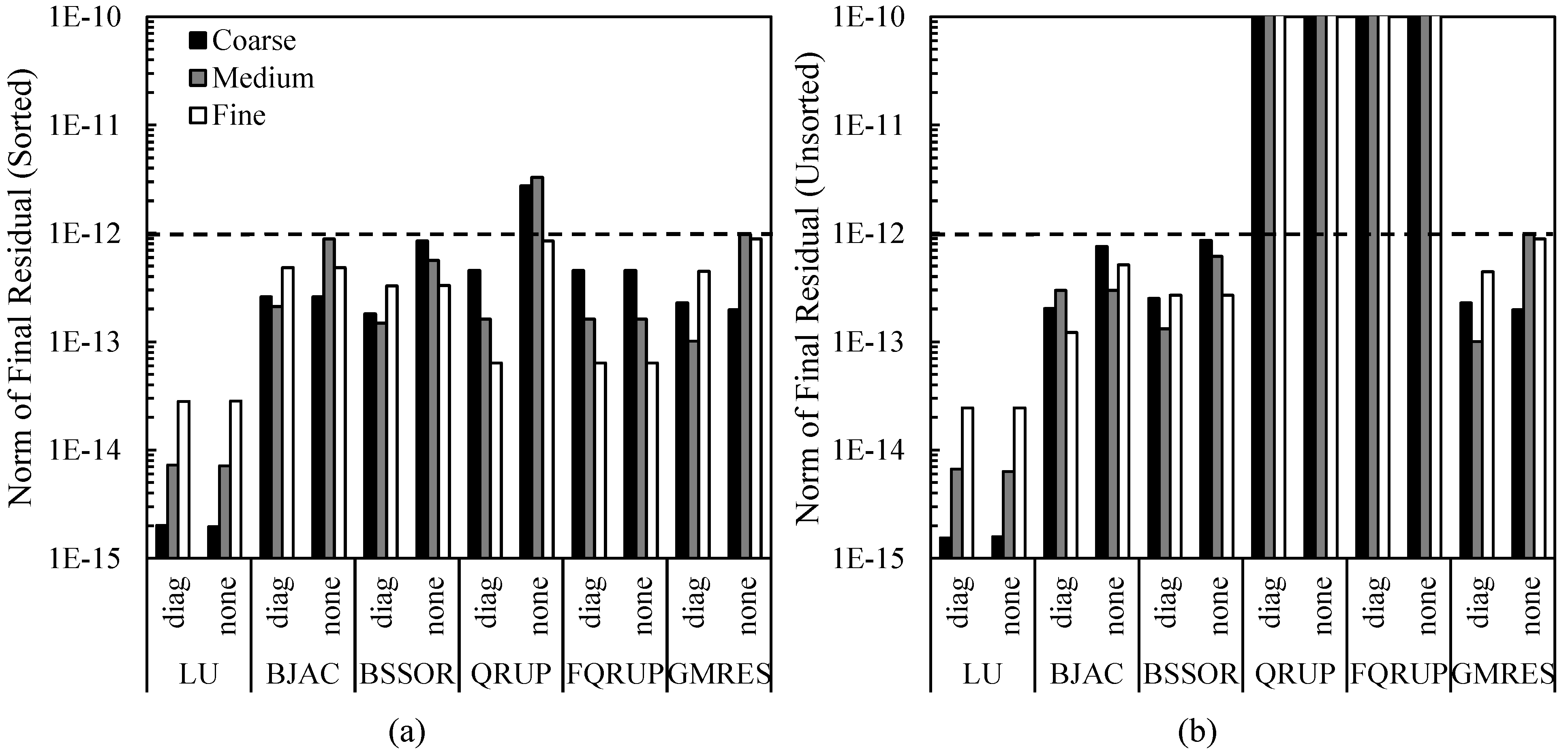
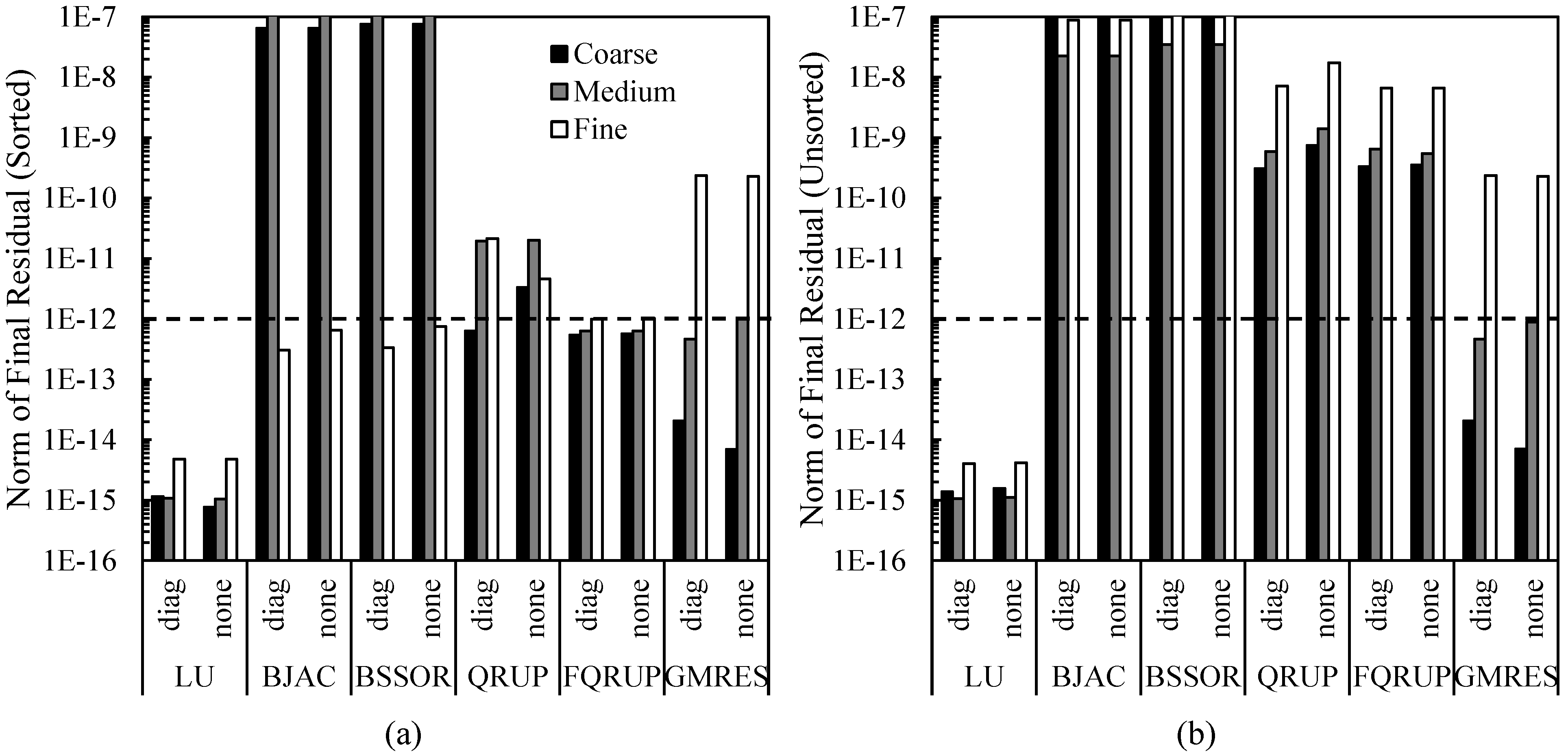
Figure 12 shows the final residuals for the various solvers. In this case, the final residuals produced by the QRUP and FQRUP solvers were relatively high, even with the system sorted. Without sorting the system, the QRUP and FQRUP residuals are unacceptably high. The QRUP solver was again helped by diagonal preconditioning, but all other solvers appeared unaffected. It can be noted that, without sorting, the BJAC and BSSOR solvers failed to converge, meaning the run times for these solvers reported in
Figure 11 are artificially low. This indicates the improvement to these algorithms provided by the upper-pentagonal sorting algorithm is even greater than seen in
Figure 11.
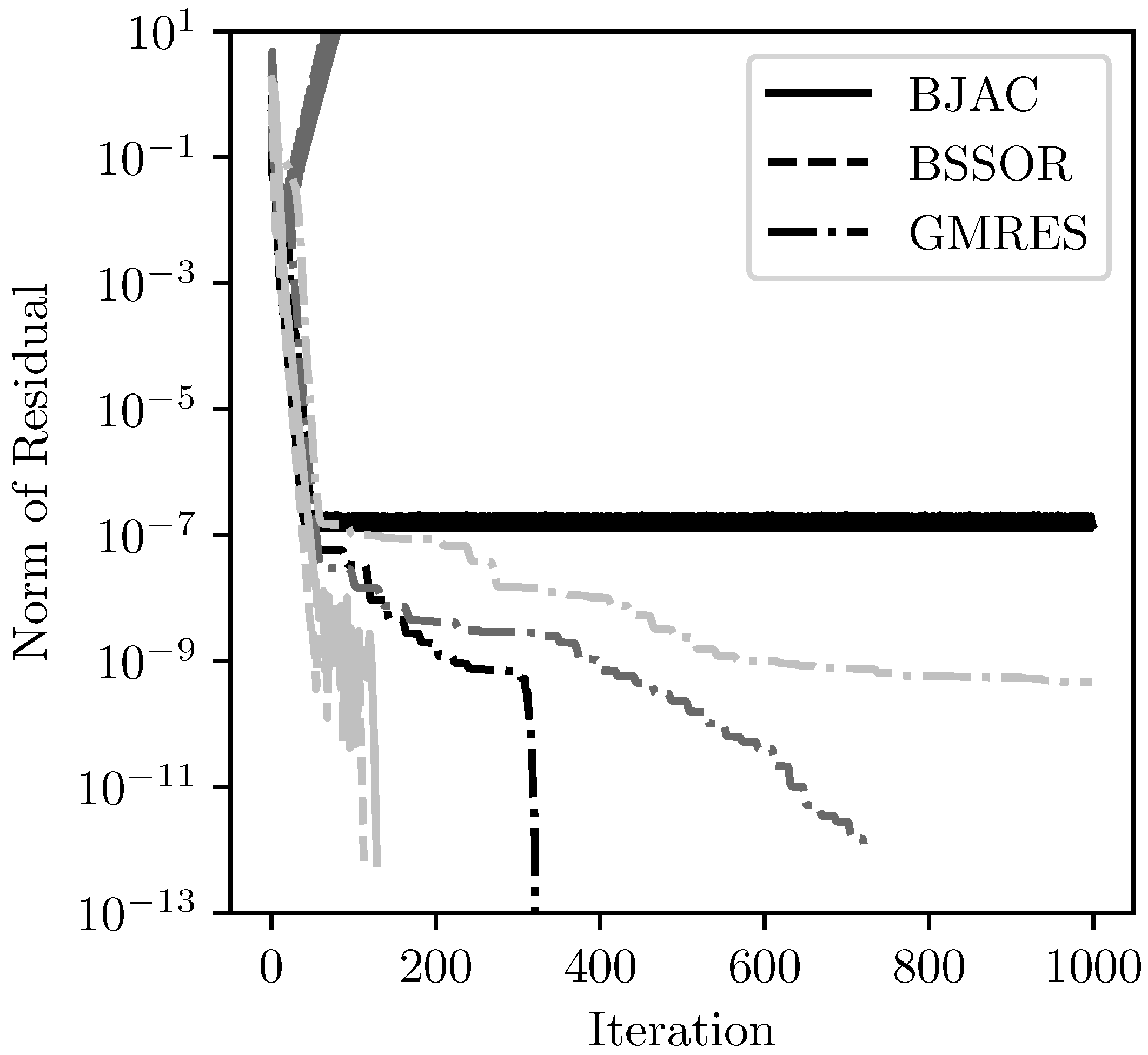
Figure 13 shows the iterative residual histories for the cases where diagonal preconditioning was applied and the system was sorted. As with the cone case, convergence was very smooth. Interestingly, the BJAC and BSSOR solvers converged in fewer iterations for the medium and fine meshes than for the coarse mesh.
4.3. Wing–Body–Nacelle Combination
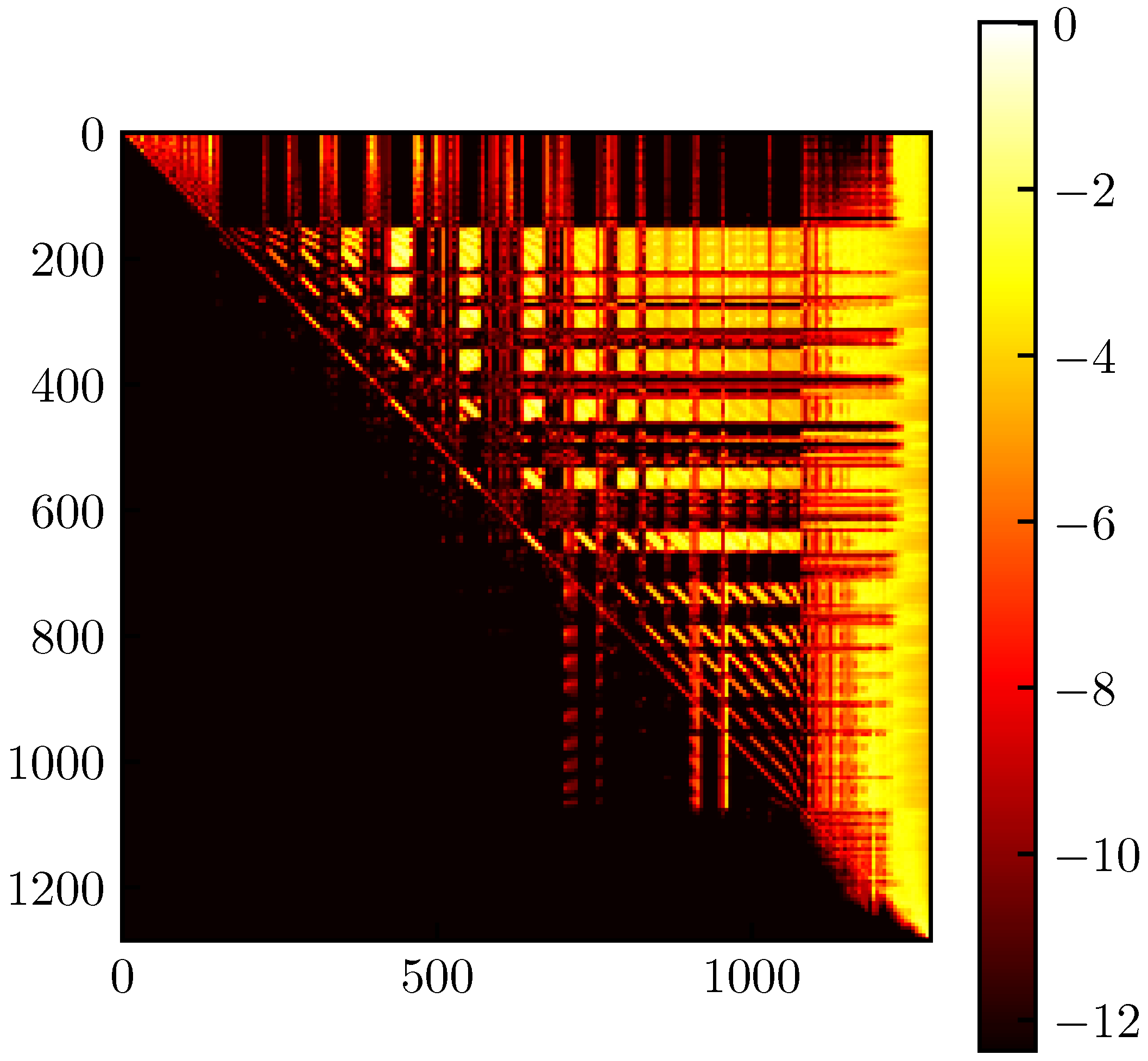
The final test case considered was a wing–body–nacelle combination. The resultant upper-pentagonal AIC matrix for the wing–body–nacelle combination is shown in
Figure 14. Its structure is somewhere in between that of the AIC matrices for the wing and cone. The upper-pentagonal portion is more dense than that of the wing but less dense than that of the cone. The AIC matrix for this case also has a large lower bandwidth, which serves to test the efficiency of the QRUP and FQRUP solvers for non-optimal cases. In addition, the nacelle on the configuration has an extremely sharp trailing edge. Because of this, the control points placed on either side of the trailing edge are very close together, making the AIC matrix more-poorly conditioned than the other cases (for how these control points are placed, see [
20]). For this case, the matrix condition number is typically on the order of 56,000 (as calculated using the singular value decomposition), whereas it was much lower for the two other cases. This gives an opportunity to test the robustness of each solver.
Figure 15 shows the solver run times for the wing–body–nacelle configuration. For this case, the QRUP and FQRUP solvers were the fastest out of all solvers for the sorted system. The BJAC and BSSOR solvers failed to fully converge for the coarse- and medium-density meshes with the system sorted, and so the timing results for these cannot be considered.
The final residuals for the wing–body–nacelle configuration are shown in
Figure 16. It is interesting to note that, even for the sorted system, GMRES failed to converge fully for the fine mesh. The BJAC and BSSOR solvers also struggled to converge, consistent with the relatively high condition number of the AIC matrix. On the other hand, the FQRUP solver consistently produced residuals less than
. The QRUP solver did not do as well, though it did produce residuals consistently less than
.
Figure 17 shows the residual history for the iterative solvers with diagonal preconditioning and the system sorted. Both BJAC and BSSOR converged relatively quickly on the fine mesh. For the other meshes, both of these solvers failed to converge. For the medium mesh, both solvers diverged. The GMRES algorithm converged more slowly as the mesh became more refined, reflecting what is shown in
Figure 16.
4.4. Solver Time Complexities
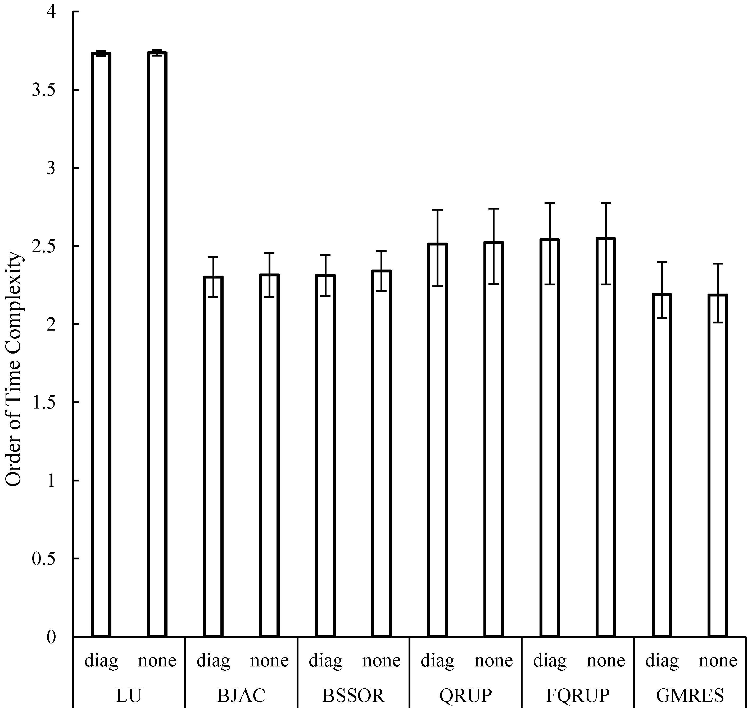
The time complexity of a method is often used to predict its performance for general cases. Time complexity is estimated by fitting a power law to the execution time as a function of the size of the linear system. This was performed here for each solver with the system sorted, as this typically produced the best results. The time complexity averaged across the three test cases considered here are shown in
Figure 18. Note that the results from the BJAC and BSSOR solvers on the wing–body–nacelle configuration are not included in this analysis, as those solvers failed to converge for all mesh refinement levels in that case. The GMRES solver was considered sufficiently converged. Not surprisingly, the LU solver showed the least variation in complexity between the different configurations, as well as the highest complexity in general. Diagonal preconditioning evidently had little to no effect on the order of complexity of any solver. In all cases, the iterative solvers had lower time complexity than the direct solvers, though the QRUP and FQRUP solvers still showed a significant improvement over the LU solver. The time complexities of the QRUP and FQRUP solvers had the largest variation between cases out of all the solvers, showing the sensitivity of these solvers to the lower bandwidth (for the cone case, the time complexity was estimated to be 2.3, whereas it was 2.7 for the wing–body–nacelle combination). Out of all the solvers considered, GMRES had the lowest time complexity by a small margin. However, this may be artificially low due to GMRES not converging for the fine mesh in the wing–body–nacelle case.
5. Discussion
In two of the three cases considered here (the cone and wing–body–nacelle cases), the QRUP and FQRUP solvers were the fastest out of all solvers considered. For the double-wedge wing, GMRES was fastest. However, despite being faster than the other solvers for the cases considered here, the QRUP and FQRUP solvers had higher time complexities than the BJAC, BSSOR, and GMRES solvers. Thus, in terms of application, the QRUP and FQRUP solvers may be best-suited for smaller systems of equations.
There are some differences in run time to note between the QRUP and FQRUP solvers. The FQRUP solver was developed to reduce computation times compared to the QRUP solver. For the cases considered here, the FQRUP solver did run slightly faster than the QRUP solver. However, as shown in
Figure 18, the FQRUP solver had a slightly higher average time complexity than the QRUP solver. Their time complexities should be the same, since the two methods require similar numbers of operations, and so the difference in measured time complexities would likely be eliminated by considering more cases. This can be seen in the variation of these time complexities.
In terms of robustness, the QRUP and FQRUP solvers resulted in final residual norms of or less, as long as the system was sorted into upper-pentagonal form. Only the LU decomposition solver consistently produced lower residuals, and the iterative solvers failed to converge for some cases. Thus, the QRUP and FQRUP solvers are very robust. Across all cases considered, the QRUP solver had higher residuals if diagonal preconditioning was not used. However, the robustness of the FQRUP solver was unaffected by diagonal preconditioning. Thus, the FQRUP solver is the more robust of the two.
The GMRES solver showed the best overall performance in terms of time complexity. It seemed to also be unaffected by diagonal preconditioning and whether the system was upper-pentagonal. This makes GMRES an attractive option for implementation in a general panel method, as separate solvers would not need to be used to maximize performance for both subsonic and supersonic cases. However, the GMRES solver performed poorly for the wing–body–nacelle case as the mesh refinement increased. For the fine mesh in this case, the QRUP and FQRUP solvers were both faster and more accurate than GMRES. Additionally, the QRUP and FQRUP solvers outperformed GMRES for the cone case at all mesh resolutions. The BJAC and BSSOR solvers also had lower time complexity than the QRUP and FQRUP solvers. However, they were less robust than GMRES at producing low residuals.
In light of this evidence, the QRUP and FQRUP solvers are viable alternatives to GMRES and other iterative solvers. Paired with the novel sorting algorithm developed here, these solvers are faster for lower system sizes and more robust than the iterative solvers considered. In addition, as discussed at the end of
Section 3.1, the QRUP and FQRUP solvers are rank-revealing and can be easily modified to solve rank-deficient systems of equations. This is a significant advantage of the QRUP and FQRUP solvers over the other solvers considered here. LU decomposition is not rank-revealing, and the iterative solvers considered struggled to converge when the matrix condition number was high. For implementation, the FQRUP solver is recommended over QRUP, as FQRUP is not sensitive to whether or not diagonal preconditioning is also used.
Though the robustness of the QRUP and FQRUP solvers has been mentioned, they failed to produce residuals as low as LU decomposition. As mentioned previously, this could likely be improved by pivoting, as is typically performed with LU decomposition. This is because some diagonal elements of the resulting upper-triangular matrix were often small (on the order of ). Swapping rows or columns to put larger elements on the diagonal could result in less numerical error, as the back-substitution step requires dividing by the diagonal elements. However, for efficiency, such a pivoting scheme would need to be designed to produce the smallest possible increase in the lower bandwidth of the system matrix. This is an area of potential future research.
Also, there was significant variation in the time complexity of the QRUP and FQRUP solvers between the three test cases. This is due to the large variation in lower bandwidth between these test cases. If the sorting algorithm could be improved to reduce lower bandwidth even further, then the performance of these solvers would improve.
It has also been shown that the sorting algorithm developed here (Algorithm 1) significantly improved the performance of the BJAC and BSSOR solvers. Thus, some developers may want to implement this sorting algorithm within a supersonic panel method, even if the QRUP or FQRUP solver is not being used.
Parallelization
As stated in the Introduction, parallelization is not a focus of this work. However, it is valuable to consider how each method could be parallelized and the effect this would have on performance. Some brief thoughts are given here. A more in-depth study into the effect of parallelization on these methods may prove valuable in the future.
LU decomposition, being essentially the same as Gaussian elimination, is inherently serial, as each step in the algorithm is dependent upon results obtained from a previous step. However, each step of both decomposition and back substitution require at least one vector operation that could be parallelized. Hence, some gains could be made by parallelizing LU decomposition. However, overhead costs would likely be significant unless some means were found to avoid starting up and shutting down a team of threads at each step of the algorithm.
The block-Jacobi method is very easily parallelized. The system of equations can be divided into as many blocks as there are available threads (or some multiple thereof). In this case, each thread holds onto a given block or blocks. The only inter-process communication then necessary is the passing of the latest update to the unknown vector. This communication is minimal if shared-memory parallelization is used. Additionally, this can be implemented in such a way that the team of threads does not need to be recreated each iteration. From experience, the authors are of the opinion that parallelization of the BJAC method leads to significant gains.
On the other hand, block-symmetric-successive overrelaxation is not easily parallelized. This is because, at each iteration, each block requires the solution from previous blocks for that same iteration. Parallelization could be implemented within each block solve. However, as with LU decomposition, the overhead costs associated with this are likely significant. In addition, the complexity of BSSOR is kept low by using small blocks along the diagonal. But the smaller these blocks are, the less effective parallelization becomes.
Parallelization of the QRUP and FQRUP solvers is essentially the same as for LU decomposition. The algorithms are inherently serial, but parallelization may be used within each step. In particular, each step requires applying the calculated Givens rotation to the rest of the two current rows, and this application could be parallelized. Again, it is likely that the overhead cost of parallelizing these rotations would be significant.
Within GMRES, most parts of the algorithm need to be performed serially. However, it would be fairly simple to parallelize the Arnoldi update step of each iteration, as this requires a matrix multiplication and then vector subtraction, both of which are easily parallelized [
31]. However, as with LU, QRUP, and FQRUP, it is anticipated that this would have high overhead costs associated with restarting the parallelization at each iteration.
Due to the high overhead costs of recreating the necessary team of processes at each step of the algorithm, it is anticipated that parallelizing LU decomposition, GMRES, QRUP, or FQRUP would be most advantageous for cases with large numbers of unknowns.
Out of all solvers considered, BJAC is very easily parallelized and has a low order of complexity. It also benefits from the sorting algorithm (Algorithm 1) developed here. However, it should be remembered that BJAC was not robust compared to FQRUP or even GMRES for the cases considered here.
6. Conclusions
In this work, the efficient solution of the linear system of equations arising in a supersonic BEM was considered. The BEM considered here was implemented on an unstructured mesh of triangles with linear-doublet-constant-source panels. While efficient solution of similar equations for subsonic flow has been considered previously, the supersonic case has not been examined. It was shown here how, in the supersonic case, the linear system of equations may be manipulated into a special form, termed upper-pentagonal. A simple sorting algorithm was presented that, for an unstructured, supersonic BEM, can result in an upper-pentagonal system matrix with relatively low bandwidth. This algorithm is based only on the mesh geometry and the freestream direction, and so may be executed without any knowledge of the actual system matrix.
A new matrix solver was then developed, based on Givens rotations, for efficiently solving a system of equations with an upper-pentagonal structure. This method is called the QRUP solver. A variation of this (called the FQRUP solver), based on Anda and Park’s self-scaling fast Givens rotations, was also developed and tested, which removed the need to calculate square roots. For comparison, other methods for solving the linear system of equations were then discussed, including LU decomposition, BJAC, BSSOR, and GMRES.
The performance of these different solvers was compared for three representative supersonic cases: a circular cone, a double-wedge wing, and a wing–body–nacelle combination. For two out of the tree test cases, the QRUP and FQRUP solvers outperformed the other solvers in terms of both speed and accuracy. Only for the wing case did GMRES run faster and have lower residuals than QRUP and FQRUP. However, for the wing–body–nacelle case, GMRES failed to converge on the highest mesh resolution. In analyzing time complexity, it was found that GMRES had the lowest time complexity of all the solvers. The time complexity of the QRUP and FQRUP solvers varied significantly with the lower-bandwidth of the system but was significantly lower than LU decomposition and only slightly higher than the iterative solvers.
While the question of which matrix solver to implement depends upon many factors, the FQRUP solver can be recommended as a fast and robust alternative to existing solvers. It also has the advantage of being easily modifiable to solve rank-deficient matrix equations, making it applicable to Neumann-based panel methods. And it is anticipated that FQRUP would benefit from parallelization to the same degree as GMRES would.
It was also shown that the novel sorting algorithm developed here can be used to significantly improve the performance of the BJAC and BSSOR solvers. Thus, the sorting algorithm has use beyond the QRUP and FQRUP solvers.
In the future, it would be valuable to see if pivoting could be implemented as part of the QRUP and FQRUP solvers. This would potentially improve the robustness of these solvers even further. In addition, improvements to the novel sorting algorithm could be made to reduce the resulting lower bandwidth. This would in turn improve the performance of the QRUP and FQRUP solvers and reduce their time complexity. This would be significant, as time complexity was found here to be the primary disadvantage to the QRUP and FQRUP solvers.
