1. Introduction
Autonomous GNC systems play a pivotal role in the success of space missions, particularly those aimed at exploring asteroids. As the space industry ventures into the cosmos, the complexities of navigating and controlling spacecraft in remote and dynamic environments demand innovative solutions. Traditional GNC methods, while effective in many scenarios, often face challenges when applied to the unique conditions presented by asteroids, such as irregular shapes, low gravity, and limited communication bandwidth.
In recent years, the integration of Artificial Intelligence (AI) techniques has emerged as a promising approach to address these challenges and enable fully autonomous GNC systems for asteroid missions. By harnessing the power of AI, spacecraft can adapt and respond to changing conditions, make real-time decisions, and navigate with unprecedented accuracy and efficiency. This paradigm shift from rule-based algorithms to AI-driven methodologies opens up new possibilities for exploration and scientific discovery.
For instance, in Origins, Spectral Interpretation, Resource Identification, and Security–Regolith Explorer (OSIRIS-REx), a mission undertaken by NASA and aimed at studying Bennu’s composition and history [
1], relative navigation techniques depend on non-autonomous landmark identification, which implies human effort and the loss of a higher degree of automation for the navigation system. In ref. [
2], a more robust technique was presented that used the shadows cast on the terrain by different features to detect those features. Additionally, their method could also infer surface properties such as localisation and size of the surface landmarks detected.
Nevertheless, OSIRIS-REx offers, too, a notable example of AI’s impact on autonomous GNC systems. This mission relied heavily on AI-based techniques for navigation and hazard avoidance. The use of machine learning algorithms enabled the spacecraft to autonomously identify safe landing sites, assess surface features, and execute complex manoeuvres with precision and reliability.
On top of that, the accuracy that is typically required for landing and Touch-and-Go (TaG) phases can only be achieved with high-resolution shape models. Achieving these models is a time-consuming task that usually defines the initial phases of the mission upon arrival at the body of interest. Trying to tackle this problem, ref. [
3] studied a vision-only autonomous pipeline used for terrain-relative positioning, landmark matching, and dense mapping that would grant autonomy to the mission by performing all of that on board. Basing their work on stereophotogrammetry techniques, the pipelines do not require any a priori knowledge of the environment.
In practice, this pipeline ingests images generated by the spacecraft’s optical sensors and feeds them to the Structure-from-Motion (SfM) algorithm, which, after performing stereo matching, is able to produce a dense point cloud and a mesh for the shape model of the body. An important aspect of this sequence is that the final shape model is built as the input data are acquired, and it does not need to wait for a batch of images to process them all. These sequential approaches are highly desirable when autonomy is in the discussion because they provide a much more flexible and adaptable approach that is robust to unexpected events.
In addition to OSIRIS-REx, several other missions have highlighted the effectiveness of AI in space exploration. For instance, the Mars rovers Spirit [
4], Opportunity [
5], and Curiosity [
6] have successfully employed AI for autonomous navigation and scientific discovery on the Martian surface. Similarly, the ESA’s Rosetta mission [
7] utilised AI algorithms for comet rendezvous and landing, demonstrating the versatility of AI-based GNC systems across different celestial bodies.
While traditional GNC methods rely on predefined rules and models, AI-based methodologies leverage data-driven approaches to adapt and learn from the environment. The generation of synthetic data needed to train the AI models has become a huge field of research as AI techniques have become more important in space exploration, which is a field for which large amounts of real-world data are not available. To address this problem, researchers have spent the last years developing pipelines to procedurally generate datasets of images that can be used to train CNNs for Image Processing (IP). More general image generation pipelines, such as the one shown in ref. [
8], address the challenges of data quantity and quality in training CNN-based sensors for applications like medical analytics and autonomous driving. In ref. [
8], the authors propose a pipeline for augmenting image datasets using computer graphics and generative neural networks, which allows for the creation of realistic and varied synthetic data. This approach improved the accuracy of CNN-based sensors compared to using only real-world data.
More related to space images, ref. [
9] introduces an open-source deep learning pipeline designed for on-orbit visual navigation, featuring two custom tools: one for generating labelled synthetic data using Blender and another for dataset curation and model training. Similarly, ref. [
10] investigates data-driven Image Processing options for a CubeSat mission around a binary asteroid system, focusing on centroid methods and Artificial Intelligence techniques. The study introduces an enhanced centre-of-brightness method and assesses the performance of various methods, finding that CNNs outperform others. Using a tailored pipeline for image generation and model training, the work highlights the importance of filtering techniques in extracting spatial information from images.
Machine learning algorithms, trained on vast datasets of simulated and real-world scenarios, enable spacecraft to make informed decisions in uncertain and dynamic environments. Reinforcement learning techniques further enhance autonomy by allowing spacecraft to optimise trajectories and control policies. In ref. [
11], the authors introduce the Autonomous Rendez-vous Transformer (ART), which uses Transformers to learn near-optimal policies and warm-start optimisers. ART outperforms other methods in predicting fuel-efficient trajectories and achieves efficient, constraint-satisfying solutions with fewer iterations and comparable runtime.
Autonomous relative navigation is a very hot topic in space exploration, and many works based on Image Processing techniques have been proposed in recent years. These include works like the previously mentioned [
10,
12], which present BennuNet, a hybrid neural network method for estimating spacecraft relative position and attitude near minor bodies using monocular vision. BennuNet targets the asteroid Bennu with synthetic training sets from the OSIRIS-REx mission. Modern architectures and data augmentation techniques improve performance over previous CNNs, maintaining high accuracy with both synthetic and real images.
All of the previously mentioned works have in common their intention to push further the levels of mission autonomy, specifically in terms of environment understanding. Given that autonomy is of particular interest in missions that try to go as close as possible to the body they are exploring, landing scenarios are an especially challenging topic.
Nevertheless, all of these pieces of research leave a gap between the steps of navigation and guidance: the decision-making involving the selection of the landing spot. This segment of the GNC process is called HDA and has been one of the main pillars of autonomy on board for specific cases where a spacecraft interacts with a body or surface.
One significant study in the field of planetary landing technology can be found in ref. [
13]. The paper focuses on advancements in autonomous HDA systems for safe landings on extraterrestrial surfaces and reports on the autonomous relay Hazard Detection and Avoidance strategy used in the Chang’e-3 lunar soft-landing mission, presenting detailed flight results that demonstrate the system’s effectiveness. Building on this foundation, the authors propose two conceptual Hazard Detection and Avoidance schemes, designed to extend the capabilities of the Chang’e-3 HDA system by integrating technological advancements for future planetary missions.
Recently, ref. [
14] showed how passive systems, i.e., those using only images as input, are capable of performing HDA accounting for features, shadows, and slopes using only semantic segmentation techniques based on CNNs.
If a spacecraft could orbit a small body and autonomously decide where to land, combining that with autonomous environment recognition and autonomous trajectory guidance and control would result in a fully autonomous GNC loop that would be able to plan a complete landing sequence, making informed decisions and assessing risks and potential hazards by itself.
One of the key elements that most of the aforementioned techniques need is a shape model of the body of interest. Building such a model could take a relatively large computational effort, which could go against the autonomy of the mission. Nevertheless, this is currently being researched, and works such as [
15] feature a limb-based method to extract edge information from images to build low- to medium-resolution shape models from multiple viewing angles, leveraging Shape-from-Silhouette concepts. By testing this method on simulated images of the asteroid Itokawa using Blender, the study examines its effectiveness in handling surface concavities, varied viewing angles, resolutions, and camera geometries, highlighting the dependence of model density on image selection and the necessity of multi-axis rotational analysis for accurate navigation. Following that line of research, ref. [
16] presents a novel Pole-from-Silhouette (PfS) algorithm, which is robust to non-zero Sun phase and shadow illumination conditions, crucial for the optical navigation pipeline of autonomous spacecraft approaching unknown small bodies. The PfS algorithm estimates the rotation pole and 3D shape of a small body using illuminated silhouette pixels, rotation rate, spacecraft attitude, and relative distance. Detailed numerical simulations and sensitivity analyses demonstrate the algorithm’s effectiveness across various scenarios and target bodies.
With that in mind, this paper proposes a novel methodology that combines multiple AI-based techniques to perform fully autonomous GNC around small bodies. In particular, the results shown in the next sections focus on Bennu. By integrating machine learning, reinforcement learning, computer vision, and neural networks, the proposed approach aims to overcome the limitations of traditional methods and enable spacecraft to navigate, explore, and interact with asteroids with unprecedented autonomy and efficiency.
It is important to clarify that the primary objective of this work is not to develop or showcase the performance of individual components within the GNC system used in the simulations presented in later sections. Instead, this paper seeks to address a critical gap in the field: the integration of existing, validated AI-based models into a cohesive, autonomous, end-to-end GNC system. While significant progress has been made in developing standalone models for various aspects of GNC, there is a lack of comprehensive frameworks that bring these components together in a fully integrated manner. This paper contributes to filling that gap by not only integrating these modules but also developing the necessary infrastructure to ensure seamless operation between components, a robust simulation environment, and the surrounding support systems required to evaluate the entire system’s performance.
By focusing on this integration, this work provides a methodology for building and testing autonomous GNC systems that can effectively utilise the advancements in AI and control algorithms, offering a path forward for more practical, real-world applications.
In the following,
Section 2 offers a comprehensive overview of the proposed methodology, highlighting its key components, implementation strategies, and potential impact on the future of asteroid exploration.
Section 3 introduces the concept of safety maps and explains how they are generated. After that,
Section 4 demonstrates the effectiveness and robustness of a fully autonomous methodology through simulations. Finally,
Section 5 closes out this paper by providing final thoughts on the results obtained and adding a critical evaluation of the challenges that are yet to be tackled.
2. Methodology
As described above, two of the main weaknesses of space exploration missions are their very-high-latency schedules and the large uncertainties present in the scenarios in which they take place. Traditionally, each of these impediments required instruction or some sort of validation from Earth-based facilities, which hindered the development of these missions, making them neither resilient nor robust to unforeseen events or unmodelled effects. Each of these contacts creates a bottleneck in the mission timeline and adds a large amount to the risks that can be assumed in the mission in aspects such as proximity to the body of interest, trajectory corrections, and mission robustness, among others.
Ideally, to remove all of these bottlenecks, a spacecraft would need to be able to tackle all unplanned events and gather all necessary information about the environment by itself. That would make ground contacts unnecessary or at least not needed with as high a frequency as is traditionally required. Tasks such as terrain recognition, relative navigation, or trajectory planning are usually highly dependent on interaction with Earth facilities and telecommanding. However, providing the spacecraft with the technology necessary to perform all of these tasks autonomously would mean a great increase in mission execution performance. In turn, the operational complexity of the mission would benefit hugely since many of the tasks that are typically performed in Earth-based facilities could be just avoided or, at the very least, see their execution frequency decreased.
However, having a spacecraft gather all this information autonomously does not solve the problem. The biggest step toward full autonomy comes after the information is collected: the spacecraft would need to make informed decisions based on the data gathered and design and plan the steps to be executed to achieve a certain goal. This element of the chain is a very challenging task. Designing an algorithm or system capable of dealing with all unforeseen events is borderline impossible to achieve with traditional techniques. Thankfully, the development of AI-based techniques in recent decades has been a great step forward towards the solution to this issue. For instance, ref. [
17] shows how applying Large Language Model (LLM)-based autonomous agents for decision-making based on user prompts to space GNC problems is feasible. The solution was developed within Kerbal Space Program Differential Games (KSPDG) challenge, which involves creating autonomous agents for satellite manoeuvres in non-cooperative space operations. Utilising prompt engineering, few-shot prompting, and fine-tuning, their LLM-based agent ranked second in the competition, pioneering the use of LLMs in space research. AI-based techniques are very good at inferring information from scarce data (when properly trained) and offer more flexible and comprehensive solutions to complex or badly posed problems, especially in very uncertain problems.
For these reasons, this work presents a novel methodology that merges HDA, relative navigation, and trajectory optimisation techniques to build a full GNC system meant for small-body environments. This system is able to select a safe landing spot autonomously and design the trajectory and guidance sequence required to land in the selected region. The whole process can be summed up in the following steps:
Insertion into an observation orbit;
Body’s surface image acquisition;
Generation of a Global Safety Map of the body;
Landing site selection;
Landing trajectory design and guidance.
Space exploration missions usually have several orbital segments dedicated to learning about the body they are orbiting that last for weeks if not months. These trajectories entail complicated geometries that are highly optimised and tailored to mission needs. For instance, OSIRIS-REx [
1] included several orbital phases at different ranges that are optimised for the scientific and operational objectives of the mission.
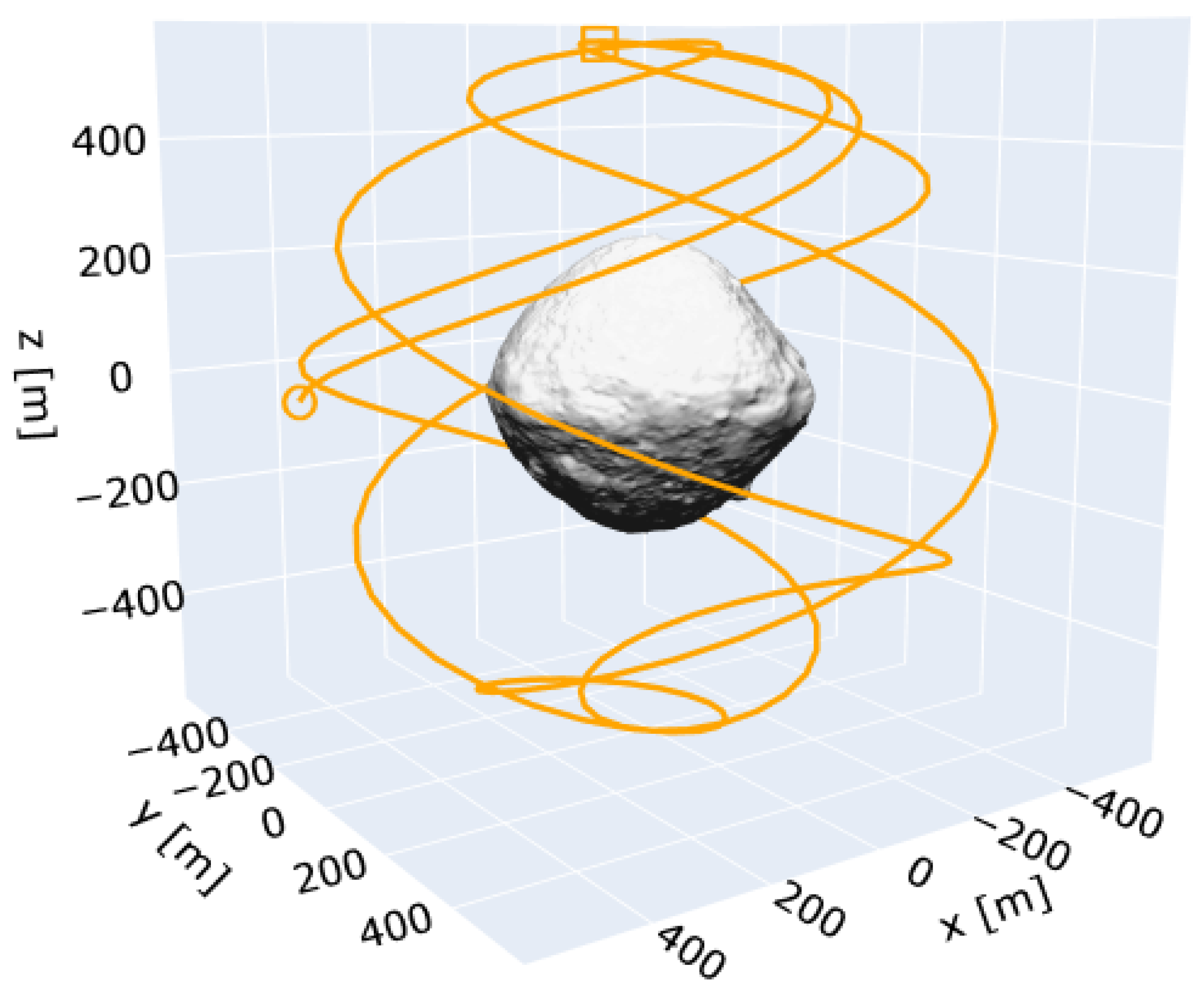
For the sake of this work, the reconnaissance trajectory design is simplified, since it is not the main focus of this paper. A polar orbit is selected to make sure that all latitudes and longitudes of the body can be observed. The orbital elements are shown in
Table 1, and a depiction of the trajectory followed (in body-fixed coordinates) is shown in
Figure 1.
From such an orbit, images are generated using a pipeline based on pyrender. A sampling rate of 2000 s is chosen, and the images generated are immediately queued for processing. This processing can be divided into two parallel lines.
On the one hand, the image is used as an input to the relative navigation module, based on BennuNet, which was introduced in the previous section [
12]. BennuNet is a set of CNNs capable of estimating the pose of a camera using monocular images. By training with synthetic images generated from multiple geometries, covering the whole range of camera positions, attitude, illumination conditions, and camera fields of view, the CNNs can learn the non-linear transformation from the 2D space (for a greyscale image) to the 6D pose space (three coordinates for the Cartesian position vector and three Euler angles with respect to the target’s body-fixed frame).
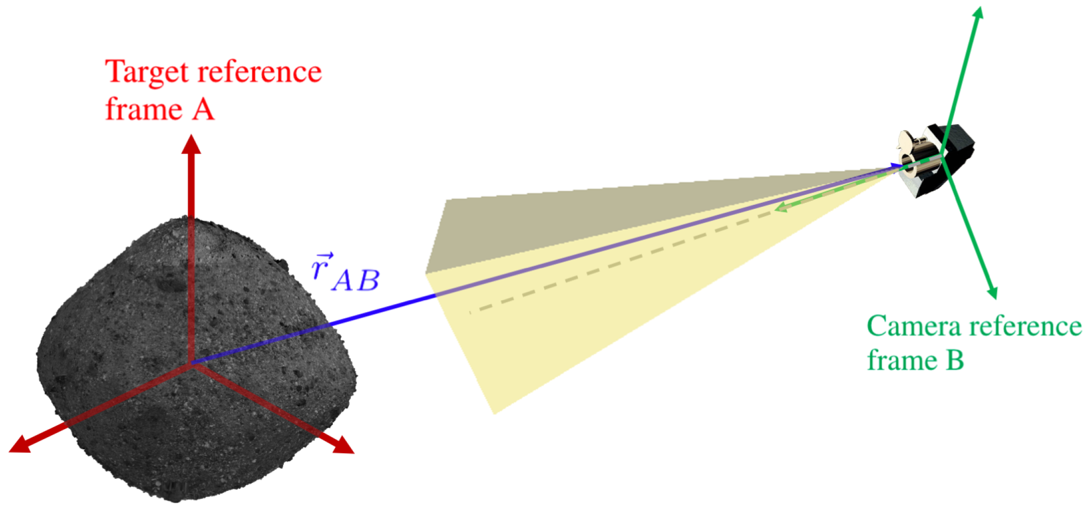
Figure 2 shows a diagram of the different reference frames used. Compared to traditional feature or landmark-based algorithms for optical relative navigation, the CNNs offer a lightweight solution that can be uplinked to the spacecraft and is robust to adverse illumination conditions, maintaining accuracy for low and high extremes of the illumination phase angle.
The set of CNNs is organised in two levels. First, a high-level classification network estimates the sector of the discretised 3D space around the target based on the input image. After testing with multiple levels of discretisation, 4 divisions latitude-wise and 8 divisions longitude-wise resulting in 32 sectors yields the overall best accuracy. Based on the estimated sector, the image is then provided as input to one among a set of low-level regression networks, each of them trained with images covering only one sector of the discretised space (with overlap between them to account for missed predictions at the sector boundaries). This low-level regression CNN provides as output the spacecraft pose vector. For this work, the attitude is assumed to be known from other sources; therefore, the output of the CNN is only the three coordinates of the relative position vector with respect to the target body-fixed frame.
On the other hand, hazards are extracted from the image using astroHda, which is a tool developed in ref. [
14]. AstroHda aims to forecast hazards for any small celestial body, leveraging the broad generalisation abilities inherent in deep learning techniques such as CNNs. It features an architecture based on Residual Network (ResNet)-34 [
18], and it takes advantage of learning techniques such as transfer learning [
19]. The dataset used to train the model was generated using a pipeline that produces images using Blender.
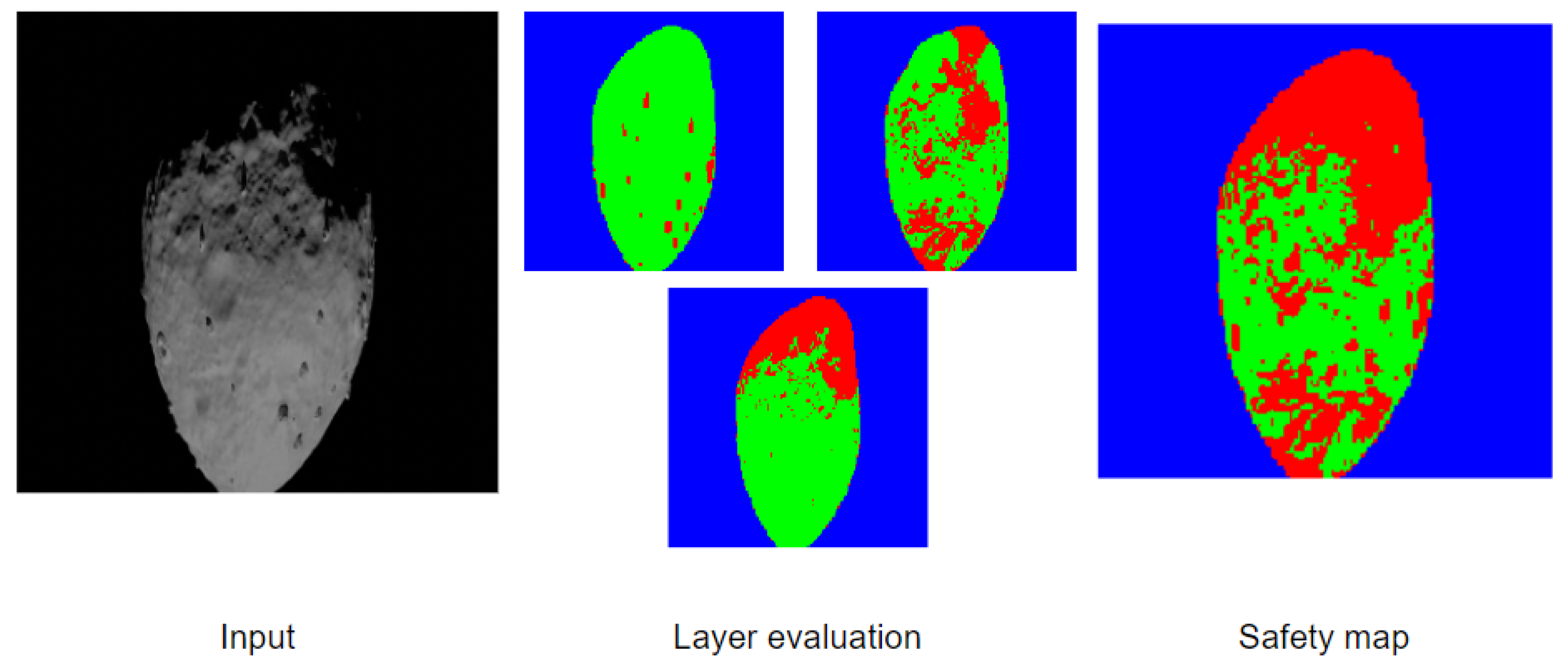
AstroHda uses semantic segmentation to detect hazards in three layers, namely, shadow detection, feature detection, and slope estimation.
Figure 3 shows an example of an input image, the three layers used, and the final safety map obtained. It is designed as a passive HDA system, i.e., it only takes observations from visual instruments, such as cameras. Freeing the system from active instruments such as LiDARs means a considerable reduction in weight and cost for the spacecraft while making the system much more accessible to small satellites.
At this point, two post-processed inputs are available: the pose estimation for the spacecraft and the safety map corresponding to the section of the body observed in the image. To project the hazard information onto a flat projection of Bennu’s surface, the light rays that the camera is taking in need to be projected onto the surface of the mesh representing the shape model of Bennu by means of ray-tracing techniques. In practice, this process translates pixel coordinates to longitude–latitude coordinates.
Figure 4 shows the basic elements involved in ray-tracing techniques. There, it can be observed how the red lines coming from the camera and pointing at a particular point on the surface of the scene object are projected onto the image plane.
Section 3 describes this process in detail.
By iterating the previous steps and projecting more and more safety maps onto the body’s surface, a GSM is obtained. The resolution of the GSM can be tailored to the needs of the mission, in particular to the landing spot selection accuracy needed and to the size of the images taken and the safety maps generated by astroHda.
The next step is to choose a spot to land on. To do that, selection criteria need to be defined. One of the most straightforward options is to simply select the safe point that is surrounded by the largest number of safe points, i.e., the safe coordinate that is furthest away from any non-safe point on the surface of the body. Other criteria might also include scientific requirements or mission-specific needs. Overlapping several criteria in a filter-like fashion could lead to more constraining conditions, which might lead to having no feasible options for landing selection, so care must be taken if a landing is to be performed.
With this approach, partial evaluations can be performed while the GSM is completed. Of course, the more complete the map is, the better informed the final spot selection will be.
Once the landing spot has been selected, a descent to the desired target may be initiated. However, model uncertainties in these environments are significant due to the inherent challenges of modelling small-body dynamics. Additionally, the models need to be computationally simple to the extent that it is compatible with space-graded computational resources. Similarly, without the presence of an established positional reference system, it is challenging to drive the navigation covariance towards zero. In order to achieve a safe landing, it is essential that the GNC system is robust towards these modelling and navigation uncertainties.
MPC is one promising approach for autonomous GNC in aerospace [
20]. It has inherent replanning abilities the inclusion of state- and thrust-based constraints, and it is optimal with respect to the cost function. Historically, MPCs have not been used in safety-critical scenarios where uncertainties are a significant factor, as uncertainty can drive MPC-based systems to become unstable. Several alternate MPC formulations have been developed over the years that aim to improve MPC in environments with high uncertainty, with stochastic MPC and tube-based MPC being the two main directions. Stochastic MPC aims to minimise the probability of constraint violations given an uncertainty distribution of the model disturbances. With this, stochastic MPC can ensure probabilistic constraint satisfaction and convergence. Tube MPC is a more conservative approach that aims to bound all possible evolutions of the state and disturbances. As opposed to the probabilistic definitions of uncertainties in stochastic MPC, the uncertainties are described as an uncertainty variable bounded to a closed, convex set. With the design of an auxiliary controller, it is possible to ensure that the evolution of the state is bounded to an invariant set centred on an MPC that assumes an undisturbed system. With the simple assumption that the model and state estimation uncertainties are bounded, tube MPC can guarantee the convergence and stability of a given system. These abilities make tube MPC particularly attractive in safety-critical environments that include uncertainties.
Two separate phases are considered for a safe descent. The first is an initial circumnavigation such that the spacecraft is positioned within a convex descent cone with its apex at the desired landing area. In this circumnavigation phase, an ellipsoidal Keep-Out Zone (KOZ) is enforced to ensure that the spacecraft does not collide with Bennu. The tube MPC has particular advantages that enable the linearisation of the non-convex KOZ. With this, only a simple Linear Quadratic optimization Problem (LQP) is required to be solved at each control iteration.
Once sufficiently within the descent cone, the GC system switches to the descent phase. Here, the descent cone may be constructed to include dangerous terrain or areas that have been mapped out previously. For the descent, the linear model used for the MPC is a linearisation of the estimated dynamics at the desired landing spot. With this, the uncertainties are at their smallest where the most precision is needed. Additionally, no linearisation of the state space is required, as the descent cone has been constructed to be convex. With this, the tube MPC for descent is also reduced to a similar LQP as in the circumnavigation phase.
Figure 5 shows an example of nine separate runs around Bennu.
With well-constructed outer bounds of both the navigational and modelling uncertainties, the tube-based MPC can ensure safe circumnavigation and descent to any desirable landing area from any initial position.
If all these elements are chained together, it is possible to perform autonomous navigation, generate a GSM of the body of interest, make an informed decision about where to land, design the trajectory required, and successfully complete the landing sequence. From these tasks, the generation of the Global Safety Maps and the development of the infrastructure to link all the elements in the chain are the key contributions of this work. Thus, the next section describes more in detail the technical specifics of the different elements developed in this paper.
3. Global Safety Map Generation
The generation of GSMs is the process of adding positioning information to a safety map obtained from astroHda. Safety maps lack any kind of information about the position or orientation a certain image is taken from. This is a design decision intended to make maps more versatile and adaptable to multiple scenarios with differently shaped small celestial bodies. In this paper, maps from astroHda [
14] are coupled with pose estimations from BennuNet [
12], making it possible to understand which section of Bennu is being processed by astroHda.
The GSM is defined as a flat projection of longitude and latitude coordinates at the surface of the body, so the process described in this section aims to transform an image of a 3D object in space into a set of observed patches of land on the surface of Bennu. The first step to achieve that is to understand where the camera is pointing at in terms of local surface coordinates.
This is performed using SPICE’s ray-tracing functionalities. Provided a position and attitude of the camera in the body-fixed reference frame, a set of rays can be generated that go through the pixels on the safety map generated by astroHda, as depicted in
Figure 4.
The resolution of astroHda’s map thus determines the number of rays that need to be traced. If these vectors intersect with the shape model, the longitude and latitude of the intersection between the body’s surface and the pixel ray is computed and the hazard label in the safety map is stored on that combination of longitude–latitude. Doing this repetitively for a sequence of images would ideally fill out a global map for the surface of Bennu.
The resolution of the GSM is set independent of the resolution of the input images and can be adjusted to the level of accuracy required by the mission. Higher resolutions will translate into longer reconnaissance stages but will increase the certainty about the hazards on the surface of the body.
During the addition of images, the same patch of land may be observed more than once. If, for instance, one of these observations happens in poor illumination conditions, there might be two different hazard labels associated with the same latitude–longitude element in the GSM. To solve this, a priority scheme needs to be imposed.
There are two different approaches to tackle this issue: rely on astroHda or stay on the conservative side. To minimise the risks, one would go for the latter and label as “hazardous” any pixel that has been detected as a “hazard” at least once. This makes the GSM obtained more robust and makes sure that no pixel is a false-positive (positive intended as “safe”) detection. However, reconnaissance orbits usually try to observe the body from multiple angles and locations around the small celestial body, and it is quite common that some of the images taken will happen to be from the dark side of the body, resulting in images with very poor illumination conditions. In the worst case, if an image is taken at the moment when the observed body is eclipsing the Sun, the safety map will result in an almost fully hazardous map, ruining many observations taken from better illumination conditions.
Figure 6 shows how different illuminations can affect the generated image, even if it is taken from the exact same position with respect to Bennu.
A middle-ground solution for this would be to include the geometry of the Sun in the process. By doing so, and since the information is available thanks to BennuNet, images taken from poor Sun-facing angles can be discarded. While this option would solve some of the problematic situations, it still would not resolve all the possible troubling cases. For instance, an image taken from a favourable Sun-facing angle could still show the shadow cast by a feature on the surface of the body. Pixels inside that shadow would still be labelled as “hazardous” and would remain so even if future images said otherwise.
With that in mind, the option chosen for this method is to trust the networks in charge of producing the safety maps, i.e., if a patch of land is detected as “safe” at least once, then it will remain as safe for the whole map completion process. This hierarchical alternative is less robust when it comes to false-positive avoidance but offers some design advantages such as detaching the process from the modules it uses and having a more generalist behaviour that needs no position-dependent pre-processing of the information.
4. Simulation Scenario and Results
The scenario used for the simulations features the asteroid Bennu as the observed body. The selection of Bennu is motivated by the use of BennuNet, but the methodology remains intact if any other small celestial body is to be studied. The model used for Bennu is shown in
Figure 7.
The simulation will replicate the orbital conditions of a mission in the observation phase, i.e., in the mission segment in which the target body is circumnavigated and images of it are taken to learn about its surface properties and features. For the sake of simplicity, since orbit design is not the subject of this work, a near-polar orbit is chosen. Near-polar orbits offer the benefit of being able to scan the surface of the body as long as they do not coincide with a particular set of frozen orbital elements that would make the orbit fly over the same ground track continuously. The orbital elements and epoch chosen are summarised in
Table 1, and the trajectory is plotted in
Figure 1. Notice how the Right Ascension of the Ascending Node (RAAN) has not been adjusted to match any particular stable illumination conditions, like the ones obtained in typical terminator orbits. This is intentionally performed so that the images taken also include situations in which the illumination conditions are poor to analyse how those image acquisitions affect the evolution of the GSM.
Other than that, light-source direction comes from the position of the Sun with respect to Bennu at each epoch, and the dynamic model used for the orbit propagation is Keplerian, both to speed the simulation up and because orbital dynamics do not affect the validity of the methodology.
The image acquisition rate has been set to 2000 s and the duration of the propagation to 24 h. This combination results in a total of 43 images. To exemplify the type of images obtained, a sample of the images obtained can be observed in
Figure 8, going chronologically from left to right and from top to bottom, for a total of 24 images out of the 43 generated.
The images generated include a variety of different illumination conditions and correspond to an almost complete coverage of the surface of Bennu. As explained in the previous section, these images are processed by BennuNet and astroHda to estimate the area of the body that is being observed and the hazards present upon it, respectively. To depict how this process takes place and the evolution of the GSM, the images chosen to be depicted in
Figure 8 correspond to a particular time series of images that are particularly helpful in showing the behaviour of the presented methodology. The captions for the images provide information about the epoch in which the image was acquired, with timesteps of 2000 s.
As introduced in
Section 3, the images shown in
Figure 8 are passed on to astroHda and BennuNet to obtain their HDA map and relative position estimation, respectively.
Figure 9 shows the generated safety maps for each of the images acquired (see
Figure 8). These maps account for illumination conditions, slopes, and features detected on Bennu and flag them as safe (in green), unsafe (in red), or deep-space (in blue). A more thorough description of the labelling process is given in ref. [
14].
The maps shown in
Figure 9 are then projected into the GSM of the body sequentially, i.e., each image acquired is processed by both astroHda and BennuNet and, following the ray-tracing techniques described in
Section 2, the safety maps are projected onto a 2D map of Bennu, whose axes are its longitude and latitude.
Figure 10 shows the evolution of such a map for the three initial images acquired. There, it can be observed how the pixels of the safety map are projected onto a map of resolution 1.0°, populating the GSM with information about surface hazards. Following the priority scheme described before, any point that is observed once and deemed safe will remain so for the rest of the evolution.
Progressively, the GSM starts to fill up, and if the surveillance orbit is capable of observing the whole surface of the body, all longitudes and latitudes are assigned a safety value that could be one of the following:
Blue: deep-space;
Red: hazard;
Green: safe.
Figure 11 shows a more intermediate evolution of the GSM. There, it can be observed how by the 18th epoch, most of the surface of the body has been observed, although a large area on the upper latitudes of the body has only been observed under poor illumination conditions. As the surveillance orbit continues to progress, more information becomes available, and even that gap is filled. Some spots along the equatorial latitudes start to take a more fixed shape: they represent features on the surface that will be flagged as hazards.
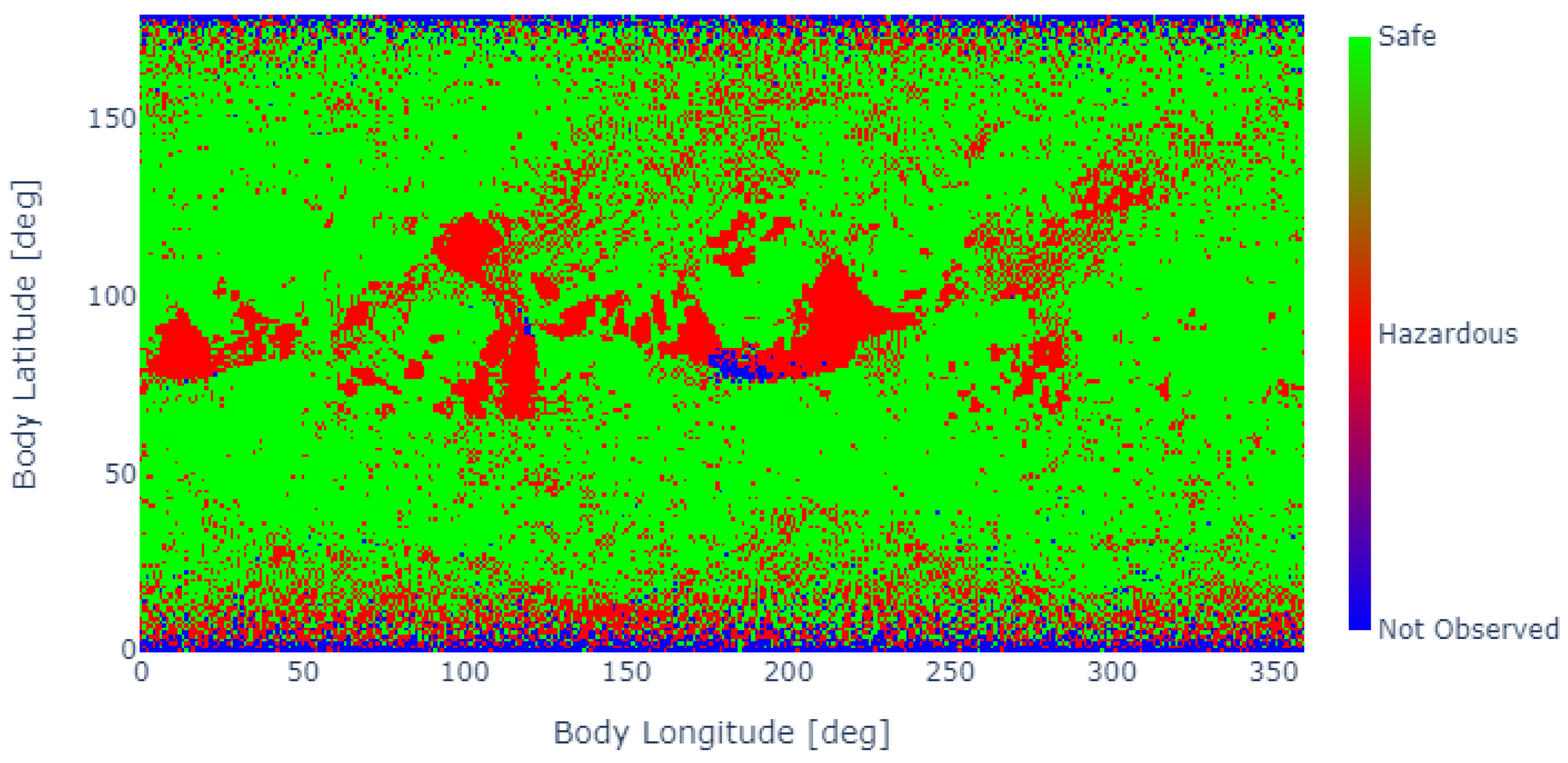
At the end of the simulation, the GSM shown in
Figure 12 is obtained. Most of the surface has been observed by this point, and the main hazard areas are identified by the algorithm. Very extreme latitudes still have unobserved or hazardous labels due to the inclination of the orbit and the fact that the body’s rotational axis is quite perpendicular to the ecliptic, making it challenging to observe those polar regions with adequate illumination conditions. Of course, this process can last indefinitely, until observations fully cover the map, but the progression of the map becomes less beneficial as fewer gaps remain.
Figure 12 shows the final map obtained after 44 images were acquired during a propagation time of 24 h. Once that map is obtained, a landing spot needs to be chosen. There are many possible criteria that can be used to select a certain landing spot, and their motivation could arise from scientific, operational, or feasibility reasons, among others. All the different criteria to be considered can be easily overlapped to filter out areas where landing is not an option, and then the optimal spot can be selected within the filtered subspace. Since it is not the purpose of this work to represent a specific use-case of this algorithm, no filters are applied and the engine of the landing spot selector is exposed.
This engine is based on hazard proximity, and evaluates, for each map pixel, the minimum distance to a hazardous area. Thus,
Figure 12 becomes the heatmap shown in
Figure 13. There, it can be observed how the areas where hazards are detected are shaded darker since their distance to a hazard is zero. There are four regions where the distance-to-hazard metric is higher, as follows:
Longitude 40°–latitude 70°.
Longitude 40°–latitude 110°.
Longitude 200°–latitude 70°.
Longitude 340°–latitude 100°.
From all of these, the algorithm shows that the best spot corresponds to a landing spot at 36° longitude and 117° latitude, with a distance to hazard of 12 cells. It must be taken into account that the resolution of the map will affect the absolute magnitude of the distance-to-hazard metric but not the qualitative results or the selection of the landing spot.
Once the landing site is selected, its coordinates are transferred to the trajectory optimisation block, which employs the MPC algorithm described previously to compute the optimal landing trajectory. The MPC is responsible for ensuring that the landing is both smooth and accurate by continuously adjusting the trajectory based on the spacecraft’s current position and velocity. As introduced in
Section 2, the MPC first identifies a point directly above the selected landing site, which serves as an intermediate target. This target point, also referred to as a hover point, is used to simplify the trajectory planning by breaking the descent into distinct phases. The spacecraft initially navigates towards this point before commencing its final descent to the surface. This fictitious waypoint is crucial for managing the spacecraft’s speed and orientation, allowing for precise control during the critical landing phase.
Figure 14 provides a visual representation of this process, showing how the trajectory, starting from the darker blue end of the line, first guides the spacecraft to the hover point until it enters the region defined by the pyramid depicted in blue in
Figure 14. From this elevated position above the landing site, the MPC recalculates the descent path, ensuring that the final approach is safe and within acceptable landing tolerances. This method allows the system to correct for any discrepancies between the planned and actual flight paths, enabling real-time adjustments that improve landing accuracy and safety.
Once the spacecraft enters the predefined region within the optimisation pyramid, the final position of the trajectory is set to the selected landing site. At this point, the MPC algorithm shifts its focus from intermediate waypoints to guiding the spacecraft directly towards the landing spot. This transition marks the beginning of the final descent phase, during which the spacecraft’s trajectory is fine-tuned to ensure a smooth and controlled approach. The optimisation pyramid, which represents the feasible space for landing, plays a crucial role in this phase by constraining the trajectory within safe parameters as the spacecraft approaches the surface.
This process is depicted in more detail in
Figure 15, where the sharp turn towards the final landing site, marked in red, becomes clearly visible. The turn signifies the point at which the spacecraft pivots from the hovering phase to the final descent. During this stage, the MPC algorithm continuously monitors and adjusts the trajectory, ensuring that the spacecraft maintains its optimal path and speed. Any deviations from the planned trajectory are corrected in real time to guarantee a precise and safe landing. This approach enables a high degree of accuracy in the final moments of the descent, reducing the likelihood of landing errors and improving mission success rates.
Figure 16 also illustrates the position and velocity errors for the simulated landing scenario. It can be observed in this figure that the position error remains approximately 10 m, indicating a minor deviation from the target landing site. Additionally, the velocity error at touchdown reaches 8 cm/s, demonstrating the system’s capability to achieve a controlled descent with minimal velocity discrepancies. These error margins highlight the accuracy of the trajectory optimisation and control algorithms in guiding the spacecraft to a precise and safe landing.
5. Conclusions and Future Work
A novel methodology has been presented where a fully autonomous GNC system for on-board mission planning is presented. The system relies on visual inputs obtained uniquely from passive sensors (cameras), and the acquired data are fully processed using CNN-based algorithms, which reduce the computational burden of the task, making it feasible to run all of this live on the spacecraft. This methodology, combined with an MPC-based trajectory optimisation block, is meant to provide the means for a spacecraft to learn about a small-body environment, select a landing spot that fits the mission requirements and needs, and design the trajectory leading to this landing sequence, all in an autonomous fashion.
At the time of writing, the code has not yet been streamlined for computational efficiency (it takes around 20 min to run the full simulation on a standard PC, no Graphical Processing Unit (GPU)) and cannot be robustly analysed to assess its performance on an on-board setup. In any case, both CNN-based and MPC blocks rely on algorithms and techniques that are well-known for their low impact on the processing power required. The piece that would require more research would correspond to the ray-tracing algorithm developed in this work, responsible for the projection of the individual safety maps onto the final GSM.
A surveillance or exploration segment is required for missions featuring this methodology where the body of interest is orbited and mapped appropriately. The duration of this phase will depend on the orbit design and the mission objectives. During this phase, images are acquired until the GSM is populated. Illumination conditions play a critical role in how fast the GSM is populated with hazard-related information.
Once the GSM reaches the level of information required, an optimal landing spot is selected based on mission requirements and a distance-from-hazard metric to reduce as much as possible the chance of landing on an unsafe or hazardous area.
This methodology introduces a new paradigm for missions to small bodies, providing a process pipeline where different components can be plugged in to fit mission specifications and sensor needs. Being able to combine surface observations with pose estimation techniques reinforces greatly the on-board navigation capabilities of any mission, and the use of ML-based techniques opens up a great deal of possibilities for autonomous solutions.
However, many questions remain after this initial step towards the objective of a fully autonomous GNC system. For instance, the study of reconnaissance orbits to optimise the population of the GSMs is a topic that could represent a field of research itself. To not only design the orbit for coverage of the body but also optimise for a hazard evaluation around particular areas of the body would require planning for the ideal trajectory coupled with ideal illumination conditions to acquire significant images that could contribute the most to the GSM.
Another aspect would be the effect of uncertainties on the pose estimation block. Studying how sensitive this methodology is to errors in the estimation of the exact position or attitude of the spacecraft would increase its robustness greatly. Depending on the results, a new priority scheme might have to be developed, with the covariance of the observations (or any other metric for the accuracy of the estimation) as a parameter to rank how reliable a certain observation and its contribution to the GSM is.
In any case, this work paves the way for autonomous missions that are capable of arriving at an unknown body and exploring it by themselves. Such a paradigm, although still distant, would represent a game-changing step forward for space exploration.


